1
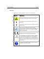
T +31 71 5813333 | F +31 71 5813334 | [email protected] | www.myAntec.com LC 110S pump OQ manual 193.0022S, Edition 1, 2013 Copyright ©2013 Antec. All rights reserved. Contents of this publication may not be reproduced in any form or by any means (including electronic storage and retrieval or translation into a foreign language) without prior agreement and written consent from the copyright of the owner. The information contained in this document is subject to change without notice. ROXY potentiostat, DECADE II, DECADE, INTRO, Sencell, Reactor cell, Reactor, ISAAC, HyREF, LINK, ADF, DECADE Dialogue, DECADE II Dialogue are trademarks of Antec Leyden BV. Whatman™ (word and device) and Whatman™ (word only) are trademarks of Whatman lnternational Ltd. SOLVENT IFD™ and AQUEOUS IFD™ are trademarks of Arbor Technologies, Inc. Clarity®, DataApex® are trademarks of DataApex Ltd. Microsoft® and Windows™ are trademarks of Microsoft Corporation. The information provided herein is believed to be reliable. Antec Leyden shall not be liable for errors contained herein or for incidental or consequential damages in connection with the furnishing, performance, or use of this manual. All use of the hardware or software shall be entirely at the user’s own risk. Table of contents 1 (of 19) Symbols Explanations of symbols & labels on the device or in user manual: Symbol Explanation Hazard symbol indicating microelectronic devices that can be damaged by electrostatic discharge when touched. Flow direction symbol for piston back flushing: inlet to flush pump. Flow direction symbol for piston back flushing: outlet from the flush pump. Quality mark of a Nationally Recognized Testing Laboratory (NRTL) in Canada and the United States. The certified device or system has successfully passed the quality and safety tests. CE (Conformité Européenne) mark for equipment that complies with the pertinent EU directives and comes with a declaration of conformity from the manufacturer. The caution/warning sign denotes a hazard. It calls attention to a procedure or practice which, if not adhered to, could result in severe/lethal injury or damage/destruction of parts or all of the equipment. Do not proceed beyond a warning sign until the indicated conditions are fully understood and met. The attention sign signals relevant information. Read this information, as it might be helpful. 2 (of 19) OQ procedure LC 110 / 110S, edition 1 Safety practices The following safety practices / protective measures are intended to ensure safe operation of the instrument. Electrical hazards Never open a device! Removal of protective panels on the instrument can result in exposure to potentially dangerous voltages which may lead to severe injury or loss of life! The instrument may only be opened by authorized service engineers of the manufacturer or a company authorized by the manufacturer. ! WARNING - RISK OF FIRE REPLACE FUSE AS MARKED WARNING - RISK OF ELECTRIC CHOCK ! Place the LC 110 / 110S on a flat and smooth surface or inside a PR 110 pump rack. Connect the detector to a grounded AC power source, line voltage 100 – 240 VAC, frequency 50/60 Hz. The instrument should be connected to a protective earth via a grounded socket using the power cord supplied by the manufacturer. The power source should exhibit minimal power transients and fluctuations. Replace faulty or frayed power cords. Solvents Organic solvents are highly flammable. Since capillaries can detach from their screw fittings and allow solvent to escape, it is prohibited to have any open flames near the analytical system! If a leakage occurs, turn of the power of the instrument and remedy the situation immediately. Regularly check for leaks and clogged LC tubing and connections. Do not close or block drains or outlets. Do not allow flammable and/or toxic solvents to accumulate. Follow a regulated, approved waste disposal program. Never dispose of such products through the municipal sewage system. Toxicity: Organic solvents are toxic above a certain concentration. Ensure that work areas are always well-ventilated! Wear protective gloves, safety glasses and other relevant protective clothing when working on the device! Table of contents 3 (of 19) Identification The undersigned engineer certifies that he/she is trained and qualified to perform an OQ on the LC 110 / 110S pump. Performer: Name Signature Initials Company Title: (Antec Leyden representative trained and qualified to perform PQ procedures) The undersigned reviewer/customer accepts that the above-mentioned engineer is trained and qualified to perform an OQ on the LC 110 / 110S pump. Reviewer/ Customer: Name Signature Company: Title: (Owner-designated authorized person) Initials 4 (of 19) OQ procedure LC 110 / 110S, edition 1 Instruments LC 110 p/n: s/n: LC 110S p/n: s/n: Isocratic HPG* Firmware version Clarity version Manufacturer Antec Supplier Date of delivery Warranty until * In case of a binary HPG system this OQ also has to be performed on the second pump. Table of contents 5 (of 19) Table of contents Symbols 1 Safety practices 2 Electrical hazards 2 Solvents 2 Identification 3 Instruments 4 Table of contents 5 Introduction 6 Determination of the inspection interval 7 Required materials to perform an OQ 8 OQ procedure 9 Preparation 9 Test 1 – Initialization of flush pump 9 Test 2 – Purge function 10 Test 3 – Minimum pressure limit and pressure display 10 Test 4 – Maximum pressure limit and leakage rate 11 Test 5 – Flow rate accuracy 11 Test 6 – Gradient accuracy 13 What to do if OQ failed 15 OQ certification 17 Comments 18 Non-conformance record 19 6 (of 19) OQ procedure LC 110 / 110S, edition 1 C H A P T E R 1 Introduction The material included in this document is provided to assist authorized personnel in performing a operational qualification. It is assumed that the individual using this manual has sufficient training in the use of analytical instrumentation and is aware of the potential hazards including (but not limited to) electrical hazards, chemical solvent hazards, exposure to pressurized solvents and UV radiation. This document describes the Operational Qualification procedure as advised by the manufacturer. It is a result from our interpretation of many regulations and laboratory practises. In addition, feedback from users and representatives helped us to finalize this procedure. The objective of this test is to check if the LC 110 / LC 110S pump is operating correctly in accordance with the manufacturer's specifications. A complete OQ of the LC 110 / 110S consists of a set of functional checks and performance test of the pump hardware. All qualification checks have to be approved, or should be marked “n.a.” if not applicable. Any deviation observed must be documented in the 'non-conformance' record. In addition, all courses of action undertaken to resolve the problems and remove the deviations shall be recorded as comments in the non-conformance record. The document must be reviewed by a person authorized by one of the laboratory directors. The review must be documented with the date and signature of this person. All relevant documents regarding this operational qualification must be filed together in one location. All information in this manual is subjected to changes without prior notice and does not represent a commitment on the part of Antec. For details on functionality, operation and theory reference is made to the instrument users manual. Chapter 1 7 (of 19) Determination of the inspection interval The routine functional inspection and review of the technical specifications must be carried out at predetermined intervals based on the intensity of use. The following intervals were established: 1. Average use from one to max. five days per week: Every 6 months 2. Intense use, i.e., day/night or more than five days a week: Every 3 months 3. Operation with buffer solutions or other salt solutions: Every 3 months 8 (of 19) OQ procedure LC 110 / 110S, edition 1 Required materials to perform an OQ Enter the specifications for the materials in use in the empty fields of the “Specification” column; the serial number is required for devices and the firmware must be entered as required. The instruments marked with * should be calibrated. Materials Specification Eluent A Methanol / water 90:10 (v/v) (HPLC quality) Fluid for piston backflush Methanol / water 20:80 (v/v) Degasser 10-32 closing plug Material PEEK Restriction capillary Back pressure of 15-30 bar (1 mL/min), 75 cm ‘red/ redstriped’ PEEK 1/16” OD, 127 µm ID Disposable syringe 10 mL Beaker (for waste) For flow rate accuracy test, variant A Flowmeter* Measuring accuracy ±1% For flow rate accuracy test, variant B Stop watch* Precision Balance* Measuring accuracy: 0.001 g Volumetric flask 50 mL For gradient accuracy test Eluent B Methanol / water 90:10 (v/v) + 0.0025 % (V/m) caffeine (HPLC quality) Mixing chamber UV detector* Flow cell 10 mm Available OQ procedure 9 (of 19) C H A P T E R 2 OQ procedure In this chapter a set of functional and performance tests are described which should be executed to check if the pump(s) is/are operating in accordance with the manufacturer's specifications. Preparation Were saline eluents or buffer solutions used with the pump? No Yes If Yes, flush the pump head(s) with water for 30 minutes. Then flush the pump head(s) with eluent A for 30 minutes. If No, flush the pump head(s) with eluent A for 30 minutes. Carried out ? No Yes Test 1 – Initialization of flush pump This test is used to check whether the flush pump is successfully initialized and is function correctly. 1. Connect the piston back flushing (tubings & wash bottle). 2. Switch the pump off and on using the power switch or using the stand-by switch. 3. The pump should initialize and the flush pump start. The flush pump can be heard and will circulating wash liquid from the wash bottle. 4. Within 30 seconds the flush pump should switch off again. Result: Passed Failed Verified by (customer): ………………………….. Comments: Deviations (Y/N): …… 10 (of 19) OQ procedure LC 110 / 110S, edition 1 Test 2 – Purge function This test checks the purge function and the fluid conveyance of the pump. 1. 2. 3. 4. 5. 6. 7. 8. 9. Switch the pump on using the power switch or stand-by switch. Connect the bottle with eluent A to the inlet tubing of the pump. Close the outlet of the purge valve using a 1/16” closing plug. Open the purge valve. Set the flow rate to 1 mL/min and press start to prime the pump head with eluent. Make sure the pump head is filled with liquid, if necessary use a 10 mL disposable syringe, and connect it to the purge tubing to prime, fill the syringe half full to prime pump head). Remove the syringe and place the beaker as a waste container below the outlet of the purge valve. Press the purge button and set the flow to 10 mL/min when working with a 10 mL pump head. The motor should run at high speed and dispense mobile phase in the waste container with a flowrate of 10 mL/min. Check if no liquid leaks from the outlet port via the PEEK closing plug. If leakage occurs make non-conformance record, retighten the plug and repeat the procedure. Result: Passed Failed Test 3 – Minimum pressure limit and pressure display This test checks the minimum pressure limit and the correct display of pressure without the application of back pressure. 1. 2. 3. 4. Set the min. pressure to 5 bar. Open the bleed purge valve. Start the pump by pressing the start/stop button. The pump should start pumping and the pressure display should display 0 bar. After approximately one minute the pump should switch off showing message “Minimum pressure limit!.....” on the LCD display. Result: Passed Failed Verified by (customer): ………………………….. Comments: Deviations (Y/N): …… Chapter 2 OQ procedure 11 (of 19) Test 4 – Maximum pressure limit and leakage rate This test checks the maximum pressure limit and whether the pump head is leaking. 1. 2. 3. 4. 5. 6. Close the purge valve. Close the outlet on the bleed valve using the filler cap. Set the flow rate to 0.05 mL/min and press start. Set the max. pressure limit with the 10 mL pump head to 200 bar. Switch the pump on using the start/stop button. The pump will start transporting liquid and the pressure should slowly rise. Check if no leakage occurs from the outlet port via the PEEK closing plug. In case of leakage make a non-conformance record, retighten the plug and repeat the procedure. 7. The pressure gradually increases to 200 bar. Once the threshold is reached the pump should switch off with a message “Maximum pressure limit!........”. 8. Check the pressure display two minutes after the pump switches off. The pressure may not be smaller than 190 bar. 9. If the pressure is smaller than 190 bar make a non-conformance record, open and close the purge valve and repeat the test again. Result: Passed Failed Test 5 – Flow rate accuracy This test is used to check the flow rate accuracy. There are two variants of this test: A) using a flow meter and B) gravimetric determination. The variant not in use should be marked at the end of this section. Variant A – Flow meter 1. Attach the restriction capillary to the high pressure outlet of the purge valve. 2. Close the purge valve. 3. Attach the flow meter to the other end of the restriction capillary. 4. Set flow to 1 mL/min. Enter a solvent factor of 0.34 for the eluent. 5. Now start the pump using the start/stop button. Verified by (customer): ………………………….. Comments: Deviations (Y/N): …… 12 (of 19) OQ procedure LC 110 / 110S, edition 1 6. Read the value measured on the flow meter after two, four and six minutes. 7. The flow meter readings (F) should be within the following limits. 0.97≤1.00≥1.03 mL/min. Enter the results in the result table. T ime (min) 2 4 6 Measured F (mL/min) Specification F (mL/min) 0.97≤ F≤1.03 0.97≤ F≤1.03 0.97≤ F≤1.03 Results Flow measurement Passed Passed Passed Failed Failed Failed Variant B – Gravimetric measurement 1. Attach the restriction capillary to the high pressure outlet of the purge valve. 2. Close the purge valve. 3. Weigh the three 50 ml volumetric flasks on the precision scale to an accuracy of 0.01 g. 4. Enter a solvent factor of 0.34 for the Eluent. 5. Set flow to 1 mL/min. 6. Place the volumetric flask under the restriction capillary. 7. Now start the stop watch and the pump simultaneously using the start/stop button. 8. After 10 minutes, remove the volumetric flask from under the restriction capillary and re-weigh it. 9. Calculate the weight of the collected eluent by subtraction of the weight of the empty volumetric flasks. 10. The calculated weight(W) should be 9.6≤W≤10.2g. Enter the result in the result table. Measured W (g) Method used: Result: Specification W (g) 9.6 ≤ W≤10.2 Variant A Passed Variant B Failed Verified by (customer): ………………………….. Comments: Result Gravimetric measurement Passed Failed Deviations (Y/N): …… Chapter 2 OQ procedure 13 (of 19) Test 6 – Gradient accuracy This test is used to check the accuracy of gradient formation in a binary high-pressure gradient system. Attach the mixing chamber behind the outlet of the pressure sensor of the second pump. The restriction capillary is installed between the outlet of the mixing chamber and the inlet of the UV detector. 1. Connect the outlets of pump 1 and 2 to the inlets of the static gradient mixer. Connect the restriction capillary to the outlet of the gradient mixer and the inlet of the UV detector. 2. Connect eluent A to pump 1. 3. Connect eluent B to pump 2. 4. Fill all channels with eluent and make sure there are no air bubbles in the system. 5. Enter a solvent factor of 0.34 for the eluents. Set flow to 1 mL/min 6. Connect the UV detector and set the wavelength to 274 nm. 7. Configure the following gradient program: Time [min] %A 0,00 5,00 5,02 10,00 10,02 15,00 15,02 20,00 20,02 25,00 25,02 35,00 100 100 90 90 50 50 10 10 0 0 100 100 %B 0 0 10 10 50 50 90 90 100 100 0 0 Flow rate [mL/min] 1 1 1 1 1 1 1 1 1 1 1 1 8. Start the gradient program and execute three repeated measurements. The first measurement will not be included in the analysis. 9. In the resulting gradient curve, each gradient step must appear as a pronounced horizontal plateau (see fig on the next page). The level of each individual plateau must correspond to the pro- 14 (of 19) OQ procedure LC 110 / 110S, edition 1 grammed % B-values of the mixture ratios. Plot the baseline at 0% B and measure signal level Hx of each individual plateau. The actual mixture ratios Cx received are calculated using the following formula: C x (%) H x (mAu) *100 H100 (mAu) x stands for the programmed step height (corresponds to the gradients). H100 is the height of the 100% step in mAU. Calculate the actual mixture ratio for each of the three steps. Enter the results in the results table on the next page. Max. deviation of each step: ± 2 % (in relation to 100 % step). Run 1 is discarded because its intended to stabilize the gradient system. Example Chromatogram of gradient run as defined in step 7. 10. Print out the resulting chromatograms and label them with attachment: High-pressure gradient_(specify repeated measurement). Chapter 2 OQ procedure Level Height (mm) Run 2 Run 3 15 (of 19) Cx(%) Run 2 Run 3 Specification (%) Results Run 2 P F Run 3 P F 10% 8 ≤ Cx ≤ 12 50% 48 ≤ Cx ≤ 52 P F P F 90% 88 ≤ Cx ≤ 92 P F P F 100% 100% Result: Passed Reference Failed When all steps of the OQ are passed, sign off this document. What to do if OQ failed Steps to take when the LC 110 / LC 110S pump fails the OQ test: 1. Finish the OQ as far as possible. If one section is failed, it may very well be that also other tests will fail that will help in finding the problem. In case tests are failed fill in a non-conformance report for every failed test. 2. Find the corresponding sections in the service documentation and see what test, recommendations and fixes are given to solve the problem. 3. If not successful in fixing the problem contact Antec Leyden for service. Verified by (customer): ………………………….. Comments: Deviations (Y/N): …… 16 (of 19) OQ procedure LC 110 / 110S, edition 1 OQ certification 17 (of 19) C H A P T E R 3 OQ certification The Operational Qualification has been carried out in accordance to the OQ procedure and has been carried out to the satisfaction of both parties. All tests as described in this document have been successfully completed, and all results are within specifications. Executing technician Technician name & signature …………………………... ……………………..…. Company Date Customer (authorised to sign) Name & signature Company/dept. Date …………………………... ……………………..…. 18 (of 19) OQ procedure LC 110 / 110S, edition 1 Comments Chapter 4 Non-conformance record C H A P T E R 19 (of 19) 4 Non-conformance record Any case of non-conformance found during the OQ procedure should be documented and signed for acceptance or corrective action taken. Table 2. Non conformance record. Ref. Non-conformance and action taken Signature customer Sign. executing technician ……………… ……………… ……………… ……………… ……………… ……………… ……………… ……………… ……………… ……………… ……………… ……………… 1 2 3 4 5 6