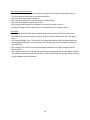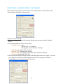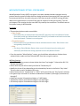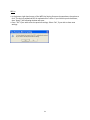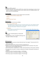
1
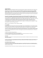
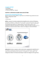
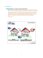
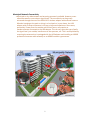
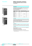
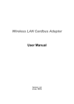
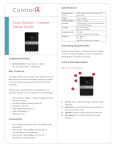
 Wireless USB Adaptor MODEL USB‐ADG‐2 WINDOWS USER GUIDE Version 1.0 LIMITED WARRANTY AIR802 guarantees that each USB‐ADG‐2 will be free from physical defects in material and workmanship under normal use for two (2) years from the date of purchase. If the product proves defective during this two‐year warranty period, call AIR802 Technical Support in order to obtain a Return Authorization Number. BE SURE TO HAVE YOUR PROOF OF PURCHASE AND A BARCODE FROM THE PRODUCT’S PACKAGING PRIOR TO CALLING. RETURN REQUESTS CAN NOT BE PROCESSED WITHOUT PROOF OF PURCHASE. When returning a product, mark the Return Authorization number clearly on the outside of the package and include a copy of your original proof of purchase. All customers outside of the United States of America and Canada shall be held responsible for shipping charges and handling charges. IN NO EVENT SHALL AIR802’S LIABILITY EXCEED THE PRICE PAID FOR THE PRODUCT FROM DIRECT, INDIRECT, SPECIAL, INCIDENTAL, OR CONSEQUENTIAL DAMAGES RESULTING FROM THE USE OF THE PRODUCT, ITS ACCOMPANYING SOFTWARE, OR ITS DOCUMENTATION. AIR802 DOES NOT OFFER ANY REFUNDS FOR THE USB‐ADG‐2 PRODUCT UNLESS IT WAS PURCHASED VIA THE AIR8O2 ONLINE STORE AND THEN THE STORE POLICIES SHALL APPLY. AIR802 makes no warranty or representation, expressed, implied, or statutory, with respect to its products or use of this documentation and all accompanying software, and specficially disclaims its quality, performance, merchantibility, or fitness for any particular purpose. AIR802 reserves the right to revise or update its products, software, or documentation without obligation to notfify any individual or entity. Please direct all inquires to: AIR802 Suite 137‐319 931 West 75th Street Naperville, IL 60540. FCC STATEMENT This USB Adaptor has been tested and complies with the specifications for a Class B digital devices, pursuant to Part 15 of the FCC Rules. These limits are designed to provide reasonable protection against harmful interference in a residential installation. This equipment generates, uses, and can radiate radio frequency energy and, if not installed and used according to the instructions, may cause harmful interference to radio communications. However, there is no guarantee that interference will not occur in a particular installation. If this equipment does cause harmful interference to radio or television reception, which is found by turning the equipment off and on, the user is encouraged to try and correct the interference by one or more of the following measures: 1. Reorient or relocate the receiving antenna 2. Increase the separation between the equipment and receiver. 3. Connect the equipment into an outlet on a circuit different from that to which the receiver is connected. 4. Consult the dealer or an experienced radio technician for assistance. FCC Caution Any changes or modifications nor expressly approved by the party responsible for compliance could void the user’s authority to operate this equipment. This device complies with Part 15 of the FCC Rules. Operation is subject to the following two conditions: (1) This device may not cause harmful interference, and (2) this device must not accept any interference received, including interference that may cause undesired operation. FCC RF Radiation Exposure Statement This equipment complies with FCC radiation exposure set forth for an uncontolled environment. This equipment should be installed and operated with minimum distance 20 cm between the radiator and your body. Users can purchase USB extension cables if necessary to comply. The device and its antenna must not be co‐located or operating in conjunction with any other antenna or transmitter. TABLE OF CONTENTS Chapter 1: Introduction 1 USB Adaptor Introduction Features System Requirements Package Contents 1 1 1 2 Chapter 2: Network Planning & Architecture 2 Ad‐Hoc versus Infrastructure Mode USB Extension Cables Alternative Antennas Applications 2 3 4 5 Chapter 3: Install Driver (Win 98, 2000, XP) 11 Notes on Windows Wireless Zero Configuration 12 Chapter 4: Install Driver (Windows Vista) Chapter 5: Configuration – Station Mode 14 17 Understanding the Utility Information More Settings ‐ Advanced WEP Encryption Key Setting WPA Encryption Setting Profile Advanced Setting System Information 17 19 20 22 23 25 25 Chapter 6: Configuration – AP Mode 26 Understanding The Utility Information General Connection Setting Understanding The AP Mode Settings Bridge Adapter 26 27 27 29 Appendix A: Troubleshooting / FAQ Appendix B: Glossary Appendix C: Specifications Appendix D: Warranty Information Appendix E: Contact Information 30 31 34 35 35 CHAPTER 1: INTRODUCTION USB ADAPTOR INTRODUCTION Thank you for your purchase of the AIR802 USB‐ADG‐2 adaptor. This USB adaptor offers great value whether you are an individual purchasing for use at home or for use in a business of any size. USB adaptors are a simple and easy way to add wireless to a computer. The majority of computers now ship with wireless cards built‐in, but users commonly find weak signals. This weak signal can occur due to several factors. One it may be too far from a wireless router or access point, most internal wireless cards do not provide significant radio frequency (RF) gain. Another factor is that almost all built‐in cards have the antennas operating horizontally, where the wireless router or access point has vertically polarized antennas. This results in significant signal loss. Whatever the resulting cause of the weak signal is, the USB‐ADG‐2 with its external and removable antenna will enhance your wireless experience. This key to successful wireless exerience is the external and removable antenna with the flexibility of using alternative antennas. The compact design makes it easy for you to travel with the adaptor. It draws its power from the USB port, so you do not need an external power supply. This adaptor supports high speed networking up to 54 Mbps per the IEEE 802.11g specification. Of course, most broadband connections are DSL or cable modems that are limited generally to less than 6 Mbps, which determines the ultimate throughput rates in accessing the Internet. As with all USB stick type devices care should be taken while connected to a laptop. FEATURES • Compact Size • USB 1.1 and 2.0 Compliant • Modulation Method: IEEE 802.11b: DSS (Direct Sequence Spread Spectrum) IEEE 802.11g: OFDM (Ortho Frequency Division Multiplexing) • Supports Microsoft Windows 98SE, Me, 2000, XP, XP x64, Vista (x32 and x64) • Easy Setup and Operation • Powered by Host Computer • Basic to Superior Security Encryption: 64‐bit, 128‐bit or 256‐bit WEP; WPA and WPA2 • 54/48/36/24/18/12/11/9/6/5.5/1 Mbps Selectable Data Rate • Supports WMM™ (Wi‐Fi Multimedia) Function • 2400 to 2485 MHz unlicensed ISM Frequency Band • 2‐Year Limited Warranty SYSTEM REQUIREMENTS • Windows System: Windows 98SE, Me, 2000, XP, XP (x32 and x64), Vista (x32 and x64) • PCs must have a device driver installed to allow communication with the USB adaptor 1 PACKAGE CONTENTS • USB Adaptor • Antenna (5dBi gain) • CD (Driver/Utility/User’s Manual) CHAPTER 2: NETWORK PLANNING AND ARCHITECTURE AD‐HOC VERSUS INFRASTRUCTURE MODE Wireless local area networks (WLAN), as specificed in the IEEE 802.11b/g standards have two different configuration modes: • Ad‐Hoc • Infrastructure Ad‐Hoc is a group of computers equipped with either WLAN cards or wireless USB adapters. The group of computers is called a Basic Service Set (BSS). They communicate with each other eliminating the need for an access point or router device. Computers in Ad‐Hoc mode cannot communicate with computers on a wired network or connect to the Internet. In our configuration software it is referred to as, “AP mode”. However this does not imply that it is an access point in the normal sense. Ad‐Hoc is shown in the diagram on the left side below. Infrastructure is where a computer or other network device equipped with with WLAN card or USB adapter communicates directly with an access point or wireless router. Infrastructure mode is the normal mode of use for most users. It is referred to as, “station mode” in our configuration software. An infrastructure example is shown in the diagram on the right above. 2 USB EXTENSION CABLE There may be circumstances where you may prefer not to plug the USB adapter directly into a USB port. This might include scenarios such as a desktop computer sitting on the floor and the desire to get the adapter up higher ontop of a desk providing less signal obstructions and improved performance. An USB extension cable would facilitate this effort. Another scenario might be that you are not using the antenna shipped with the product and have installed a coaxial cable from the USB adapter to an antenna installed outdoors for external network connectivity. The coaxial cable, depending on the type and size could cause some strain on the adapter in an USB port. In this case, the use of a USB extension cable would be useful. There are two types of USB connectors, Type A and Type B. The Type A is a rectangular connector and Type B is a square connector. Type A is shown in the photo below. If your application requires using the USB adapter outside of the USB port on your computer, then an USB extension cable is appropriate. You will need a USB Type A (male) to plug into the computer and a USB Type A (female) to plug in the USB adapter. USB extension cables by standards specification are limited to 15 feet in length. AIR802 currently manufactures USB extenssion cables in 3 and 6 foot USB lengths and they are available at (http://www.air802.com/home.php?cat=428). 3 ALTERNATIVE ANTENNAS The USB‐ADG‐2 is sold with a 5dBi gain dipole type antena. This antenna radiates radio frequency (RF) in 360 degrees. Users may depending on their application and needs find alternative antennas to be useful. AIR802 manufactures a wide range of antennas which could be used with this adapter. Antennas alone do not determine the distance that you may reach. It is a factor of the RF transmit power and receiver sensitivity (with the USB adapter and the access point/router device), any cabling loss, free space loss and antenna gain and other factors such as interference in the 2.4 GHz ISM band. With line‐of‐sight, antennnas and a proper installation, a point‐to‐point network can be achieved for 1 mile or more. Outdoor antennas can be used indoors and will almost always will provide better results than an indoor antenna of the same gain. To install an antenna remote of the USB adapter, you will need to purchase a special AIR802 antenna cable asssembly. The cable assembly will require a RP‐SMA (plug) at the USB adapter end. AIR802 outdoor antennas will require a N(male) connector at the opposite end of the cabe. Indoor Type • ANOM2409‐RPSMA Dipole antenna with 9dBi gain – use if higher gain is required • ANOM2406 Directional 6dBi gain – use to focus RF energy in a specific direction • ANOM2448 Directional 4.8dBi gain, with 100cm (7.87”) cable – use for directional gain Outdoor Type *Requires AIR802 Antenna Cable Assembly • ANOM2408 Omnidirectional (360 degree), 8dBi gain, Outdoor • ANOM2410 Omnidirectional (360 degree), 10dBi gain, Outdoor • ANOM2412 Omnidirectional (360 degree), 12dBi gain, Outdoor • ANYA2408 Yagi (directional), 8dBi gain, Outdoor • ANYA2410 Yagi (directional), 10dBi gain, Outdoor • ANYA2412 Yagi (directional), 12dBi gain, Outdoor • ANYA2415 Yagi (directional), 15dBi gain, Outdoor • ANYA2418 Yagi (directional), 18dBi gain, Outdoor 4 APPLICATIONS Residential Network – Computer to Router Connectivity • Residential users commonly do not receive adequate signal coverage througout their home. It is often assumed that replacing the existing router antenna for a model with higher gain will resolve the issue. While in some circumstances this may help, often the problem is that the internal wireless card in the computer produces to weak of a signal to reach the router. Installing the AIR802 USB‐ADG‐2 device will normally significantly improve this scenario. External antennas simply provide better performance. 5 Computer to Public Wi‐Fi Access Point (Hot Spot Connectivity) • Whether in a local coffee shop, airport or hotel lobby, the computer user may frequently encounter a weak signal or connectivity. Your connection can depend upon how well the public hot spot was engineered and installed. However, the connectivity can be greatly improved upon through the use of the USB adapter and its external antenna. An external antenna is the key to successful wireless connectivity. 6 Municipal Network Connectivity • Municipal or city wide network are becoming commonly available. However, users often have weak or non‐existent signal levels. The connectivity can be greatly enhanced through the use of the USB‐ADG‐2 wireless adapter with external antenna. Whether lounging at the pool or sitting in a local park or in your home, the USB adapter with an external antenna is the key to improved experience. Some users, particularly if away from the outside wall of their home, may require an outdoor antenna connected to the USB adapter. This can vary upon the type of walls, the signal level just outside, interference in the spectrum, etc. This is accomplished by removing the antenna that is packaged with the USB adapter and installing an AIR802 professional antenna cable assembly to an AIR802 outdoor type antenna. 7 Remote Building with Single Computer – Network Connectivity to Main Building or Home • Frequently a remote building, whether it be a detached garage from the home or a commercial building separate from the main building may have a single computer that needs connectivity between each other. The USB adapter can easily be the solution. For best results, an external antenna, generally a yagi antenna should be installed on the outside of each building pointed at each other. This will require an AIR802 antenna cable assembly from the USB adapter to the exterior antenna. The same would be done to the indoor router. Contact AIR802 for assistance in determining the best antenna and cable assembly for your specific network. 8 Yacht Connectivity in a Marina • If you have a single computer in a yacht and desire to connect to the local marina wi‐fi access point, the USB adapter is an excellent solution. For the best results, users should remove the antenna that comes with the USB adapter and install an AIR802 antenna cable assembly from the USB adapter to an outdoor antenna. • The common solution for yacht owners worldwide has been to install an AIR802 USB adapter to a CA195 cable assembly. CA195 is the most popular antenna cable assembly in use by yacht owners. It is chosen for its small outside diameter (0.195”). However, for minimum signal loss, AIR802 recommends CA400 cable assemblies (0.405” outer diameter). Yacht owners generally install the AIR802 ANOM2412 omnidirectional antenna, which is a 12dBi antenna. This antenna can be used with the AIR802 marine antenna mount. The USB adapter requires the use of an RP‐SMA (plug) connector at one end of the cable, and a N(female) at the opposite end for an AIR802 outdoor antenna. For yachts with multiple computers, AIR802 offers another solution utilizing our AP‐G200 high power indoor router/bridge. 9 RV User to Campground Access Point Connectivity • Many campgrounds offer inadequate wi‐fi coverage. Often they may be using common residential broadband routers, which are completely inadequate for the application. AIR802 has provided high power and high quality equipment through professional installers to many RV parks and campgrounds. However, a vast majority may have poor quality service offerings. Even under the best installations, users may have insufficient signal. This is almost always due to a combination of a weak internal wireless card in the computer and metal walls of a recreational vehicle. The use of an external antenna is key to a satisfying experience. Sometimes the external antenna maybe sufficient for improved signal coverage. For the best possible coverage, RV owners should install an antenna exterior to the recreational vehicle and connect it to the USB adapter through an AIR802 cable assembly. The cable requires the use of a RP‐SMA (plug) for the USB adapter at one end and a N(female) connector for outdoor AIR802 antenna. 10 CHAPTER 3: INSTALL DRIVER (Win 98, 2000, XP) The installation & driver CD will automatically activate the autorun
installation program after you insert the disk into your CD drive.
Step 1:
Insert the installation & driver
CD into your CD-ROM drive.
Step 2:
Click Next to continue.
Step 3:
Click Next to install at the designated folder.
Or, click “Browse” to select a folder.
11 Step 4:
Start copying files until the
installation is finished.
Step 5:
Click Finish to complete
installation.
Step 6:
After finishing installing the driver and utility on your system, plug the USB
adapter into the USB port of your PC. Windows XP/2000 will automatically
detect the USB Adapter.
Notes On Windows Zero Configuration Service
Microsoft Windows XP includes the Zero Configuration Service which is used to configure your
wireless client. After clicking on the computer icon on Windows bar in the lower right hand
corner of your screen, you may encounter the following screen. If you have this screen,
Windows Zero Configuration Service is managing your wireless connection and not the Client
Utility.
12 The client manager for the USB adapter and Windows Wireless Zero Configuration Service will
not operate together. You may elect to use the Windows Zero Configuration Service (if using
your existing internal wireless card) or the Client Utility (for the USB adapter).
Enable Windows Wireless Zero Configuration Service
Click Start >> Control Panel >> Administrative Tools >> Services to open the Services
configuration window. Select Automatic in the Startup Type field of Wireless Zero Configuration
Service to enable the Wireless Zero Configuration Service and click apply. The default Startup
Type value of Wireless Zero Configuration Service is Automatic. Disabling Windows Wireless Zero Configuration Service
Click Start >> Control Panel >> Administrative Tools >> Services to open the Services
configuration window. Select Disabled in the Startup Type field of Wireless Zero Configuration
Service to disable the Wireless Zero Configuration Service and click apply.
13 CHAPTER 4: INSTALL DRIVER (Windows Vista) Plug your USB dongle into USB interface, windows
Vista will search for compatible driver to install.
Step 1:
Select “Locate and install the driver software”,
Windows will guide you through the process of
installing driver software for your device.
Step 2:
Insert the installation disc into the CD-ROM and
click “next” to continue installation.
Step 3:
Windows Vista searches for the software and it will
be installed successfully.
14 Step 4:
After installation, right click the network icon on the
Windows Vista System Tray, and click “Connect to
a network”.
Step 5:
Select a network to connect to and click “Connect”.
Step 6:
Click “Connect Anyway” if the network is
an unsecured network.
15 Step 7:
USB Dongle successfully connected to
the network, click “Close”.
Note:
In Win98SE, Win2000, ME, XP, XP x64, the Device name is:
“(AIR802) IEEE 802.11b+g USB Adapter”
In Windows Vista, the Device name is:
“Atheros AR5007UG Wireless Network Adapter”
16 CHAPTER 5: CONFIGURATION – STATION MODE Station mode is synonomous with infrastructure mode. This is the most commonly used mode for the majority of users. Through this mode, users may access the Internet by connecting wirelessly to an Access Point or wireless router. The USB‐ADG‐2 adapter uses its own management software. After installing the driver outlined in either Chapter 3 or Chapter 4 and the USB adapter has been inserted into a USB port, a new icon should appear in the Windows System Tray automatically such as shown below: If the icon is in red, it means that USB adapter configurations is invalid or incomplete. Double click on that icon and the configuration window (maybe referred to as the Utility Screen) will pop up as shown below. UNDERSTANDING THE UTILITY INFORMATION – STATION MODE Mode: • Located in the upper right, this is where you may select either Station (Infrastructure) mode or AP (Ad‐Hoc) mode. •The normal mode for most users will be the default Station mode. Available Networks: • Located on the left‐hand side of the screen, it displays the SSID of available networks • Click the Refresh button to update the current networks and their respective SSIDs that are turned on and operating at any given moment. • Double click on the chosen SSID from the “Available Networks. 17 Current Network Information: • After double clicking on the chosen SSID, the network information will appear under the Current Network Information on the right‐hand side. • The channel number will be indicated. • The Type field indicates if in Infrastructure or Ad‐Hoc mode. • The TX rate indicates the transmission rate. • The Encrypt field indicates if the network is running encryption or none. • The More Settings button is described in more detail below in the next section. Link Status: • Information about the link status is shown on the bottom one‐third of the utility screen. • The BSSID of the associated access point or wireless router is displayed in the “Link Status” field. • The “Signal Strength” and “Link Quality” are displayed below the BSSID and described with percentages (link quality is a measurement of receiving and transmitting performance over the radio link). • The number of TX and RX Frames are displayed underneath the Signal Strength and Link Quality fields. • The number of TX Frames indicate the total amount of data going out of the adapter towards the network, whereas the the number of RX Frames indicate the total amount of data coming into the adapter from the network. 18 MORE SETTINGS – ADVANCED SETTINGS – STATION MODE After clicking “More Settings” from the Utility main settings window, a new window, titled, “More Settings” will appear as shown below. General Connection Setting: • To adjust settings in the General Connection Settings area, you must click the “Change” button. • The following parameter choices can be made: • Transmit (TX) rate: Auto 802.11b (1, 2, 5.5, 11 Mbps) 802.11g (6, 9, 12, 18, 24, 36, 48, 54 Mbps) • SSID: Can enter specific SSID or click Any • Network Type: Infrastructure or Ad‐Hoc • Authentication: Auto, Open, Shared, WPA, WPA PSK, WPA2, WPA PSK • Encryption: Disable, WEP, TKIP, AES • After any desired changes have been made to the above parameters, click “Apply” as shown in the diagram at the top of the following page to confirm the changes. Note that the Change/Apply button alternate between each other. 19 WEP ENCRYPTION KEY SETTING – STATION MODE Wired Equivalent Privacy (WEP) encryption is the basic standard wireless network security protocol used to protect wireless data from being hacked and intercepted. WEP encrypts each frame transmitted from the radio using one of the Keys entered in the WEP settings window. When an encrypted frame is received it will only be acceptd if it decrypts correctly. This will only happen if the receiver has the same WEP key used by the transmitter. The default state in Encryption Setting is WEP disabled. First Steps: • Three authentication modes are available: • Open System • Uses default key to authenticate the station(PC) and the Access Point/Wireless Router. Once both parties are Authenticated, the station(PC) is allowed to send and receive data from the network. The data is not encrypted. • Shared Key System • Station and Access Point/Wireless Router authenticate each other. Data frame is also encrypted by the WEP key. • Auto • The Access Point/Wireless Router takes control of network security setting and station(PC) will follow the setting required from the AP/Wireless Router. • From the previous “More Settings” screen, you should have selected one of above three authentication modes and have selected WEP from the encryption options. WEP Key Settings: • The WEP Key Setting screen as shown below has three “key lengths”. Select either 64, 128, 256 (bit) key length. • Select which key set will be used by the field of “Default Key ID”. • Modify the 4 sets of keys depending on the selected key format in the field of “Key Value”. The key value is used in hexadecimal format. • Select the key format “hexadecimal” or “ASCII” will be used from the “Key Format” selection. • Encryption keys are made of a random combination of numbers (0 through 9) and letters (A through F) • 64‐bit keys require 10 hexadecimal digits or 5 ASCII digits • 128‐bit keys require 26 hexadecimal digits or 13 ASCII digits • 256‐bit keys require 58 hexadecimal digits or 29 ASCII digits 20 802.1x: • In the bottom right‐hand corner of the WEP Key Setting Screen as shown above, the option to click “The key is provided via 802.1x authentication” exists. If you click this press the button, then “Apply”, the following window will open. • Press “Yes” if you wish to use the previous settings. Select “No”, if you wish to have new settings. 21 WPA ENCRYPTION SETTING – STATION MODE WPA and WPA2 (Wi‐Fi Protected Access) is an advanced wireless security standard. WPA is more complex and offers more robust security authentication and encryption features. WPA is commonly known as WPA‐TKIP and WPA2 as WPA‐AES. • There are three protocols choices (drop down choices under Protocol): • TLS (Transport Layer Security) • TLS authenticates peers by exchanging digital certificates. • Applicable Fields • User Name • Password • Validate Server Certificate • Pre‐shared Key Passphrase • Certificate • PEAP (Protected Extensible Authentication Protocol) • PEAP authentication does not require client certificates • Applicable Fields • User Name • Password • Validate Server Certificate • Pre‐shared Key Passphrase 22 • TTLS (Tunneled Transport Layer Security) • TTLS authentication does not require client certificates • Applicable Fields • Phase2Auth (with the following drop down choices) • PAP • CHAP • MSCHAP • MSCHAPv2 • User Name • Password • Validate Server Certificate • Pre‐shared Key Passphrase PROFILE – STATION MODE Profiles permit saving of different connection and authentication settings for different network setups. For example, you may have one configuration for the office another for your home network where security settings or other information is different. When switching networks, select the network profile name previously saved and click the load button. 23 ADVANCED SETTINGS – STATION MODE Under this utility screen, advanced settings can be adjusted. These settings are not recommended to be changed unless by an advanced wireless user. • Language • Two languages are currently available • English • Traditional Chinese • Power Consumption Setting • Continous Access Mode (CAM) • This is the default mode • Maximum Power‐Saving Mode • Provides the lowest power saving capability, but throughput will be lower than other modes • Fast Power‐Saving Mode • Saves less energy than CAM mode, but provides better throughput than with Maximum Power Saving Mode 24 • Other ‐ Miscellaneous Settings • PSP XLINK Mode • Use with Xlink Kai online gaming • WMM QoS (Quality of Service) Mode • WMM Quality of Service is based upon a subset of the IEEE 802.11e standard • WMM prioritization minimizes delay in the wireless network for time‐sensitive appplications like VoIP, Video or Gaming • Country Roaming • Allow users to predefine whether the adapter will be used internationally. Different countries have different settings for wireless adapters. • Two options are available • World mode is the default setting – Adapter will adapt to associated access point/router • User Select – User may choose specific country from the pull down list • Fragmentation Threshold Setting • Permits adjustment of fragmentation threshold point from 256 to 2346 bytes • RTS/CTS Threshold • Permits adjustments of the RTS threshold point from 0 to 2347 bytes SYSTEM INFORMATION – STATION MODE Click on the Information button, a pop‐up window will display the driver version, utility version and the USB adapters MAC address. 25 CHAPTER 6: CONFIGURATION – AP MODE AP mode is synonomous with Ad‐Hoc mode in this device. AP mode does not imply that the device can become a full access point in the normal sense. Ad‐Hoc mode allows computers with the USB adapter to communicate with each other, eliminating the need for a wireless router or access point. The limitation is that you will not have access to the Internet. Most users will use the station (infrastructure) mode. The USB‐ADG‐2 adapter uses its own management software. Once the USB adapter has been inserted into a USB port, a new icon should appear in the Windows System Tray automatically such as shown below: If the icon is in red, it means that USB adapter configurations is invalid or incomplete. Double click on that icon and the configuration window (maybe referred to as the Utility Screen) will pop up as shown below. UNDERSTANDING THE UTILITY INFORMATION – AP MODE Mode: • Located in the upper right, this is where you may select either Station (Infrastructure) mode or AP (Ad‐Hoc) mode. • Select Access Point. The normal mode for most users will be the default Station mode. Connect Station List: • Client computers that connect to your USB adapter, configured as an AP will have their MAC addresses populated into the Station MAC Address list. 26 Current Network Information: • Indicates the current channel • Indicates the SSID of the AP • Indicates the WEP encyrption status (enabled or disabled) • Indicates the transmit power level, Level 0 (maximum) to Level 3 (minimum) Other Information: • The Tx Frame shows how many frames have been transmitted by the “soft” AP. • The Rx Frame shows how many frames have been received by the “soft” AP. For further configuration, click on “More Setting” button to access the Access Point Setting Window. GENERAL CONNECTION SETTING – AP MODE After clicking “More Settings” from the Utility main settings window, a new window, titled, “Access Point Setting” will appear as shown above. Press the Change button to modify the “General Connection Settings”, and press “Apply” to save the changes. The “Change” and “Apply” button are alternatively shown in the same position. UNDERSTANDING THE AP MODE SETTINGS – ACCESS POINT MODE Wireless Mode: • Three modes for the “soft AP” are selectable: • 802.11b+g Mixed Mode *normal suggested mode • 802.11g only • 802.11b only Channel: • Selectable from channel 1 to 13 – Default is channel 6. 27 SSID: • Modify the SSID as desired. • Check the “Hide SSID” box to hide the SSID from outside clients attempting to connect to your “soft AP”. If checked, computers outside of your network search for available networks, your specific SSID will not be displayed. Transmit Power:
• Four optional radio frequency transmit power level are selectable: • Level 0 (Maximum Power) *default mode • Level 1 • Level 2 • Level 3 (Minimum Power) Authentication:
• Two authentication choices are available: • Open System *default mode • Uses default key to authenticate the station(PC) and the Access Point/Wireless Router. Once both parties are Authenticated, the station(PC) is allowed to send and receive data from the network. The data is not encrypted. • Shared Key • Station and Access Point/Wireless Router authenticate each other. Data frame is also encrypted by the WEP key. WEP: • Select either to Disable (default) or Enable WEP encryption. • Click the Setting.. button. The WEP Key Setting screen will appear as shown to the right. WEP Key Settings: • The WEP Key Setting screen as shown below has three “key lengths”. Select either 64, 128, 256 (bit) key length. • Select which key set will be used by the field of “Default Key ID”. • Modify the 4 sets of keys depending on the selected key format in the field of “Key Value”. The key value is used in hexadecimal format. • Select the key format “hexadecimal” or “ASCII” will be used from the “Key Format” selection. • Encryption keys are made of a random combination of numbers (0 through 9) and letters (A through F) • 64‐bit keys require 10 hexadecimal digits or 5 ASCII digits • 128‐bit keys require 26 hexadecimal digits or 13 ASCII digits • 256‐bit keys require 58 hexadecimal digits or 29 ASCII digits 28 • Fragmentation Threshold Setting • Permits adjustment of fragmentation threshold point from 256 to 2346 bytes • RTS/CTS Threshold • Permits adjustments of the RTS threshold point from 0 to 2347 bytes • Preamble • The Preamble can be set for long or short. The default setting is long. • MAC Address Filter • Click on the Settings button as indicated below on the left. • A table will appear as shown below on the right. • Select Enable or Disable • Enter up to 16 MAC addreses to filter – Click Apply. • Bridge Adapter • To use the adapter as a Bridge Adapter, you must first select the adapter from the drop down menu. 29 APPENDIX A: TROUBLESHOOTING The USB icon does not appear in our icon tray. • Make sure that you have installed the Utility from the attached CD. The Utility is installed and appears in the icon tray, but no networks are found. • If no networks are listed, you may not be within range of any network – higher gain antennas maybe necessary. • If you have a portable computer, move it within close range to an access point or router and see if the network can be seen. If so, the adapter is functioning and your first attempt may have been out of range. Why won’t the Utility Tool funtion properly in Windows XP? • If you are using Windows XP as your operating sytem, the “Zero Configuration” feature/tool of Windows XP must be disabled first, then the AIR802 Wireless Utility can be used. To disable: Click Start >> Control Panel >> Administrative Tools >> Services. Select Disabled in the Startup Type field of Wireless Zero Configuration Service to enable the Wireless Zero Configuration Service. The default value of Wireless Zero Configuration Service is Automatic. How can I improve the signal levels even further? • If your USB adapter is plugged directly into a computer low to the floor, you may benefit by adding an USB Extension cable and then placing the USB adapter on the top of a desk or table, at a higher level more in line with the wireless router or access point. • Wireless communications is a 2‐way communications link. Often, the weak link is the PC itself, but if after installing the USBadapter you still have weak communications it maybe due to interference from other devices in the 2.4 GHz band and/or your wireless router or access point may offer low RF output power and receiver sensitivity. If this is case you may attempt to upgrade the antenna on the router and the USB adapter or purchase a high quality router. • You can consider alternative antennas for the USB adapter with higher gain omnidirectional “rubber duck” options, or directional gain atennas where the RF energy is focused towards a specific direction. 30 APPENDIX B: GLOSSARY 802.11 – The Institute of Electrical and Electronic Engineers (IEEE) has created a number of wireless standards. This helps to insure that products built to comply with a specific standard are interoperable with one another even if manufactured by different companies. 802.11b – Specifies a maximum data transfer rate of 11 Mbps, an operating frequency of 2.4 GHz, and WEP encrypion for security. Commonly referred to as Wi‐Fi. 802.11g – Specifies a maximum data transfer rate of 54 Mbps, an operating frequency of 2.4 GHz and is backwards compatible with 802.11b. Commonly referred to as Wi‐Fi. Access Point – An interworking device that seamlessly connnects wired and wireless networks together. Ad‐Hoc – An Ad‐Hoc wireless LAN is a group of computers, each with a WLAN card, connected as an independent wireless LAN. Ad‐Hoc wireless LAN is applicable at a departmental scale for branch SOHO operation. BSS – Basic Service Set is an 802.11 interworking framework that includes an Access Point. Computers in a BSS must be configured with the same BSSID. CTS (Clear to Send) – An RS‐232 signal sent from the receiving station to the transmitting station that indicates is is ready to accept data. Client – A workstation or PC on a network. Default Gateway – The IP Address of either the nearest router or server for the LAN. DHCP – Dynamic Host Configuration Protocol is a method in which IP addresses are assigned from a pool of IP addresses by a server dynamically to clients on the network. DHCP is used for Dynamic IP Addressing and requires a dedicated DHCP server on the network. DNS – Domain Name System is used to map readable machine names (Internet domain names) into IP addresses. DSSS – Direct Sequence Spread Spectrum is a method the wireless cards use to transmit data over the frequency spectrum. The other method is frequency hopping. Direct sequence spreads the data over one frequency range (channel) while frequency hopping jumps from one narrow frequency band to another many times per second. 31 Dynamic IP Adress – An IP address that is automatically assigned to a client station in a TCP/IP network, generally by a DHCP server. Network devices that serve multiple users, such as servers and printers, are usually assigned static IP addresses. ESS – Extended Service Set is a set of two or more BSSs (multiple access points) that form a single network. Firmware – Programming code that is written onto read‐only memory (ROM) or programmable read‐only memory (PROM). Once written into memory, it is retained even after the device is turned off. IEEE – Institute of Electrical and Electronics Engineers is a professional society that promotes the development of standards. Infrastructure Network – One or more computers or other devices, each with a wireless adapter, connected to an Access Point. An infrastructure wireless network connected to a wired network is referred to as a Basic Service Set (BSS). A set of two or more BSS in a single network is referred to as an Extended Service Set (ESS). ISM Band – Industrial, Scientific and Medical Band operates in the frequency band 2.4 and 2.48 GHz. It is the only unlicensed band approved worldwide. LAN – A group of computers and other peripheral devices connected to share resources through wired or wireless technology, within a small geographic area. Protocol – A standard set of rules for exchanging information (format, timing, sequencing, error checking, etc.) between computers or network devices. Roaming – In infrastructure mode, this refers to a computer moving out of the range of one Access Point and connecting transparently to a new Access Point. SSID – Service Set Identifier is a unique network identification name. All client devices and Access Points that share the same SSID are able to communicate with each other. Static IP Addressing – A permanent or manually assigned IP address. Once a static IP adress is assigned, a computer or network device will use the same IP address every time it reboots and logs on to the nework, unless manually changed. TKIP – Temporal Key Integrity Protocol is part of the IEEE 802.11i encryption standard for wireless LANs. TKEP is the next generation of WEP (Wired Equivalency Protocol), which is used to secure 802.11 wireless LANs. TKIP provides per‐packet key mixing, a message integrity check and a re‐keying mechanism. WEP – Wired Equivalent Privacy mechansim is based on a 64, 128 or 256 bit algorithm. 32 WPA – Wi‐Fi Protected Access was created by the Wi‐Fi Alliance as a data encryption method for 802.11 wireless LANs. WPA is an industry‐supported, pre‐standard version of 802.11i utilizing TKIP. WLAN – Wireless Local Area Network is a group of computers and associated devices that communicate with each other wirelessly. 33 APPENDIX C: SPECIFICATIONS Standards
IEEE 802.11b (DSSS)
IEEE 802.11g (OFDM)
Antenna
Detachable 5dBi Dipole
Antenna Connector RP-SMA Jack (Reverse Polarity SMA)
Frequency
802.11b: 2.4 to 2.497GHz
802.11g: 2.4 to 2.4835
Modulation Method
802.11b: DBPSK/DQPSK/CCK
802.11g: BPSK/QPK/16QAM/64QAM
Data Transfer Rate
802.11b: 11,5.5,2,1 Mbps
802.11g: 54,48,36,24,18,12,9,6 Mbps
Operation Mode
Infrastructure (Use of Access Point or Router) or Ad
hoc
RF Transmit Power
17 (+/-2) dBm @ 11b
14 (+/-2) dBm @ 11g
RF Receiver
Sensitivity
802.11b: < -82dBm @ 8% FER
802.11g: < -70dBm @ 8% FER
Security
WEP (64/128/256bit), WPA, WPA-PSK, WPA2, WPA2PSK, TKIP/AES
Operating Systems
Windows 98SE, Me, 2000, XP x64, Vista, MAC (v10.3
and v10.4), Linux
Management
Windows-based configuration utility and status
monitoring
Humidity
5 to 90% (non-condensing)
Dimension
27.2 x 79.2 x 12.35mm
1.07” x 3.11” x 0.486”
Certifications
FCC for North America and CE/ETSI for Europe
34 APPENDIX D: WARRANTY INFORMATION BE SURE TO HAVE YOUR PROOF OF PURCHASE AND A BARCODE FROM THE PRODUCT’S PACKAGING PRIOR TO CALLING. RETURN REQUESTS CANNOT BE PROCESSED WITHOUT PROOF OF PURCHASE. IN NO EVENT SHALL AIR802’S LIABILITY EXCEED THE PRICE PAID FOR THE PRODUCT FROM DIRECT, INDIRECT, SPECIAL, INCIDENTAL, OR CONSEQUENTIAL DAMAGES RESULTING FROM THE USE OF THE PRODUCT, ITS ACCOMPANYING SOFTWARE, OR ITS DOCUMENTATION. AIR802 DOES NOT OFFER ANY REFUNDS FOR THE USB‐ADG‐2 PRODUCT UNLESS IT WAS PURCHASED VIA THE AIR8O2 ONLINE STORE AND THEN THE STORE POLICIES SHALL APPLY. AIR802 PAYS FOR GROUND SERVICES ONLY. ALL CUSTOMERS LOCATED OUTSIDE OF THE UNITED STATES OF AMERICA AND CANADA SHALL BE HELD RESPONSIBLE FOR SHIPPING AND HANDLING CHARGES. APPENDIX E: CONTACT INFORMATION AIR802 LLC Suite 137‐319 931 West 75th Street Naperville, IL 60565 USA GENERAL INQUIRIES Monday through Friday 8:30am‐5:30pm CST Tel: 630‐428‐3108 Fax: 630‐428‐1575 Email: [email protected]
TECHNICAL SUPPORT For technical support, visit www.AIR802.com and click on Support to view your options. 35 36