1
TR-151A / TR-151E
Vehicle/Asset Tracker
User Manual
Version 1.0.0
Table of Content
1. Introduction and Features.............................................................................................. 4
1.1 Introduction ............................................................................................................4
1.2 Features .................................................................................................................4
1.3 Hardware................................................................................................................5
2. Start-up.......................................................................................................................... 6
2.1
2.2
2.3
2.4
2.5
2.6
2.7
Accessories .............................................................................................................6
Install SIM card and Battery ......................................................................................7
Charging the battery .............................................................................................. 10
TR-151 with magnetic holder ................................................................................... 11
Turn on/off the device............................................................................................. 13
Button Description ................................................................................................. 13
DIP switch ............................................................................................................ 16
3. TR-151 Management Setting ........................................................................................ 17
3.1 Install the USB driver ............................................................................................. 17
3.2 Install, Update, Uninstall the TR Management Center program...................................... 18
3.3 TR Management Center Screen Introduction .............................................................. 24
3.3.1 Tracker and GPRS Tool Bar ............................................................................. 26
3.3.2 Query Tool ................................................................................................... 27
3.3.3 Data Output Area ......................................................................................... 28
3.4 Skype Setup.......................................................................................................... 29
3.5 Firewall Setting...................................................................................................... 35
3.6 TR Management Center System Requirement ............................................................. 36
3.7 Copyrights and Example Information ........................................................................ 36
4. TR-151 Management Operation .................................................................................... 37
4.1 TR Management Center Basic Setup.......................................................................... 37
4.2 Tracker Management .............................................................................................. 38
4.2.1 Adding and setting a TR-151 tracker................................................................ 39
4.2.2 Tracker Management ..................................................................................... 46
4.2.2 Deleting a TR-151 tracker .............................................................................. 47
4.2.2 Editing a TR-151 tracker ................................................................................ 48
4.2.5 Selecting Country/ Area code ......................................................................... 50
4.3 Instruction of using TR Management Center ............................................................... 51
4.3.1 Instruction for Beginners ............................................................................... 51
4.3.2 Receiving data from TR-151 via GPRS network.................................................. 52
4.3.3 Send GPRS command to TR-151 ..................................................................... 54
4.4 TR Management Center Data Query .......................................................................... 56
4.4.1 Look up for history data................................................................................. 56
4.4.2 Export the data into KML format ..................................................................... 58
4.4.3 Delete the history data in the database............................................................ 59
4.5 Send SMS by Skype to set TR-151............................................................................ 60
4.5.1 Set Geo-fence .............................................................................................. 60
4.5.2 Set the SMS default return phone number........................................................ 68
4.5.3 Set the Maximum GPS Fixing Time .................................................................. 69
4.5.4 Set default report mode................................................................................. 70
4.5.5 Set SOS phone number ................................................................................. 72
4.5.6 Set the Parking Mode’s parameters.................................................................. 73
4.5.7 Set the Sleeping Mode’s parameters ................................................................ 74
4.5.8 Set the GPRS parameters............................................................................... 75
TR-151
page 2
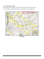
4.6 Using Google Map .................................................................................................. 77
4.6.1 Google map data .......................................................................................... 78
4.6.2 Google map operation ................................................................................... 80
5. Operating the TR-151 ................................................................................................... 81
5.1 How to set SOS number of TR-151 by SMS?............................................................... 81
5.2 How to set TR-151 to immediately report its position by SMS?...................................... 82
5.3 How to set TR-151 to periodically report its position by SMS? ....................................... 83
5.4 How to set TR-151 to immediately make report its position via GPRS network? ............... 84
5.5 How to set TR-151 to periodically report its position via GPRS network? ......................... 85
5.6 Tracking/Monitoring TR-151 by GPRS ........................................................................ 86
5.7 Displaying the location on map ................................................................................ 87
5.8 How to set TR-151 enter Geofence mode? ................................................................. 89
5.9 How to make TR-151 do Voice monitor function? ........................................................ 92
5.10. How to set the parameters of Parking Mode? ........................................................... 93
5.11 How to set the parameters of Sleeping Mode? .......................................................... 94
5.12 The return format from TR-151 .............................................................................. 96
5.13 SMS Configuration................................................................................................ 98
5.13.1 SMS Configuration _ SMS Default Return Phone Number................................. 100
5.13.2 SMS Configuration _ Maximum GPS Fixing Time ............................................ 101
5.13.3 SMS Configuration _ Default Report Mode Setting .......................................... 102
5.13.4 SMS Configuration _ GPRS Setting .............................................................. 104
TR-151
page 3
1. Introduction and Features
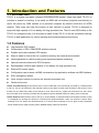
1.1 Introduction
TR-151 is a durable and water resistant GPS/GSM/GPRS tracker. Users can install TR-151 on
vehicles or assets for tracking. It can send out SMS with its location (longitude and latitude) to
user’s cell phone by GSM network or to personal computer by internet connection of GPRS
network. Then users can track the location of their vehicles or assets. TR-151 is designed to
equip with high capacity of Li-ion battery for long operation time. There is one SOS button on the
TR-151 for emergency help. It is very easy to install or hide TR-151 in the car to perform tracking.
TR-151 is ideal application for vehicle tracking and equipment/assets monitoring.
1.2 Features
z
High sensitive GPS chipset
z
Combination of GPS ,GSM/GPRS wireless network
z
Durable and water resistant GPS tracker
z
Easy to install or hide in the car to perform tracking. No external wires needed.
z
Ideal application for vehicle tracking and equipment/assets monitoring
z
Optional external antenna for GPS reception
z
Rechargeable 2100mA high capacity Li-ion battery for long operation time
z
External DC power supply
z
Configuration can be done via SMS commands or by application software via USB interface.
z
SOS (emergency) button.
z
Voice monitor function to monitor the sound/conversation live.
z
Geofence function
NOTE: Voice Monitoring function allows user to send a SMS with voice monitoring command by a cellular phone
to TR-151. TR-151 will call back to the returned number in the SMS. And then user can listen to the sound or voice
around TR-151. While users listen to the sounds or voice around TR-151, people who around TR-151 won’t know
they are under voice monitoring. Please refer to page29 to get the detailed method of making voice monitoring.
NOTE: Geofence feature allows user to set up to 10 permissible or restricted areas whose shape is either circular
or rectangular for tracking the vehicles or monitoring the equipment/assets. Users can choose to receive alarm
message if TR-151 enters the restricted areas or to receive alarm message if TR-151 gets out the permissible
areas. Please refer to page 26-28 to get the detailed setting method of Geofence.
TR-151
page 4
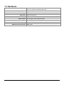
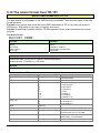
1.3 Hardware
GSM module:
Operating temperature:
-20° to 55° C
Antenna Type:
GPS patch antenna
Dimension:
86.7*48.9*32.5 mm
Battery:
LED indicator:
Interface:
Casing:
GPS external antenna port:
TR-151
TR-151A: Siemens GSM 850/1800/1900
TR-151E: Siemens GSM 900/1800/1900
2100mA rechargeable Li-ion battery
For Charging, GPS, GSM and Status.
Mini USB port for connecting to PC
Water resistant (IPX4)
MMCX port
page 5
2. Start-up
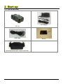
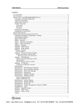
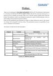
2.1 Accessories
TR-151
USB Cable
AC charger
Battery
Mounting bracket with magnet (optional)
TR-151
page 6
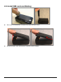
2.2 Install SIM card and Battery
z
Use a coin or screwdriver to loosen the screw on back cover.
z
Lift up the back cover and remove it as the direction shown.
TR-151
page 7
z
z
z
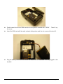
Push forward the cover of SIM card slot to the position marked with “OPEN”. Then lift up
the cover.
Insert the SIM card with its metal contacts facing down and the cut corner at the top left.
Plug the battery connector into socket. Be aware that the red wire must be plugged on the
top side.
TR-151
page 8
z
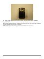
Please put the connector wire under the battery, and then put the battery into battery
compartment.
NOTE: After installing the battery, the status LED will emit red light. After the LED go out, please
wait for 5 seconds before turning on the power.
NOTE: Please take out the battery if you do not use TR-151 for a long time.
TR-151
page 9
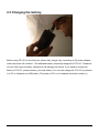
2.3 Charging the battery
Before using TR-151 for the first time, please fully charge it by connecting to AC power adapter
under the power-off condition. (The attached battery is specially designed for TR-151. Please do
not use other type of battery; otherwise it will damage the device. If you need to change the
battery of TR-151, please contact your local dealer.) You can also charge the TR-151 by connect
it to PC or Notebook via USB cable. (The power of PC or of notebook should be turned on.)
TR-151
page 10
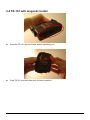
2.4 TR-151 with magnetic holder
z
Insert the TR-151 with the Power button side facing out.
z
Push TR-151 into the holder until it clicks in position.
TR-151
page 11
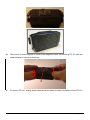
z
There are 4 circular magnets on back of the magnetic holder for attaching TR-151 onto the
metal material of vehicle or machine.
z
To remove TR-151, slightly push outward the two sides of holder, and slide out the TR-151.
TR-151
page 12
2.5 Turn on/off the device
●
Turn on: After installing the battery, the status LED will emit red light. After the LED go out,
please wait for 5 seconds before turning on the power. Press the power button for 3~4
seconds. When the device is turned on, GPS will do cold start to get fixed its position for
the first time with the green GPS LED on. If location is fixed, the LED will blink. It is
suggested that you stay at outdoor places or near the window where TR-151 can receive
the better GPS signal when you turn on the device.
NOTICE: If it does not successfully get the location fixed after turning the power on,
TR-151 may be located in the weak signal area or on the move.
●
Turn off: Press the Power button for 3~4 seconds. When the power is turned off, LED will
go out.
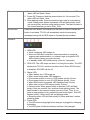
2.6 Button Description
TR-151
page 13
Power button
1. Power On: Press and hold the power button for 3-4 seconds. The
status LED will flash 2 times
2. Power Off: Press and hold the power button for 3-4 seconds. The
status LED will flash 1 time.
3. Enter parking mode: Press the power button once to enter parking
mode. When power button is pressed, LED will flash slowly (once
per second) first, and then enter parking mode. The flash number is
the second number you set in Park_Time.
SOS button
Press the SOS Button, the status LED will flash 3 times to indicate the
button is activated. TR-151 will immediately send out emergency
messages along with its GPS report to 3 preset phone numbers.
Indicator
1. GSM LED:
y Voice monitoring: LED keeps on.
y When no SIM card is inserted, network searches in progress,
ongoing user authentication, or network login in progress: LED
blinks quickly (about once per second).
y In standby mode: LED blinks slowly (once for 3 seconds)
2. GPS LED: The LED keeps on when it is fixing the location. The LED
blinks when TR-151’s location has been fixed. When GPS function
is disabled, GPS LED will be off.
3. Status LED:
y When battery low: LED keeps on.
y When enter setup mode: LED keeps on.
y Press power button to turn on: LED flashes quickly 2 times.
y Press power button to turn off: LED flashes quickly 1 time.
y When SOS button is pressed: LED flashes slowly 3 times.
y When error occurs: LED flashes quickly 5 times.
y Parking mode: When power button is pressed, LED will flash
slowly (once per second) first, and then enter parking mode. The
flash number is the second number you set in Park_Time. If you
want to stop parking mode, press the power button again. The LED
flashes quickly 3 times and it will exit parking mode.
y Sleeping mode: LED will flash slowly 60 times and then it enters
sleeping mode.
4. Power LED:
y The LED emits orange light when charger is plugged for charging
the battery.
y The LED goes off after the battery has been fully charged.
TR-151
page 14
USB connector
There are two functions of the USB connector:
1. Connect TR-151 to PC by a Mini USB cable and setup all its
features and functions from application software through PC.
2. Charge the battery by connecting a USB cable.
Microphone
For voice monitoring use.
External antenna
For you to connect a MMCX external GPS antenna.
connector
TR-151
page 15
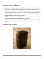
2.7 DIP switch
On
Off
Switch 1
Enable TR-151 to automatically power Users have to press the power button
on when it is connected to external
to power on TR-151 whether external
power.
power is connected or not.
Switch 2
All LED works as user mode.
Make all LED except status LED go off
for secret tracking. Status LED works
as user mode.
Switch 3
Setting Mode (Status LED keeps
emitting red light)
User Mode
Switch 4
Sleeping Mode
User Mode
Note: You can set the switch by a little tweezers or pen point or toothpick.
TR-151
page 16
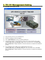
3. TR-151 Management Setting
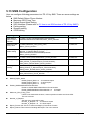
3.1 Install the USB driver
1.)
Insert the Driver CD into your CD-ROM driver.
2.)
AutoRun installation window will appear.
3.)
Click “Install USB Driver” button to install the USB driver.
4.)
You will see two folders. If your Windows is Vista version, please double click to open
“PL2303_USB_Driver_for_Windows_Vista” folder and double click on “PL-2303 Vista
Driver Installer.exe” to begin installation. Follow the instruction to complete the installation
process.
5.)
If your Windows is XP or 2000 version, please double click to open
“PL2303_USB_Driver_for_Windows_2000_XP” folder and double click on “PL-2303
Driver Installer.exe” to begin installation. Follow the instruction to complete the installation
process.
TR-151
page 17
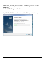
3.2 Install, Update, Uninstall the TR Management Center
program
3.2.1 Install TR Management Center
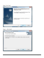
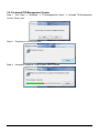
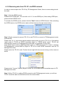
Step 1: Click “English PC Software” button to install the TR Management Center program.
TR-151
page 18
Step 2: Click “Next”
Step 3: Click "Install"
TR-151
page 19
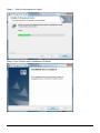
Step 4:
Wait for the program to install
Step 5: Click "Finish" when installation is finished
TR-151
page 20
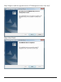
3.2.2 Update TR Management Center
If you download a new version of the TR Management Center software from the Globalsat
website, you could install the downloaded software to upgrade the TR Management center
without un-installing the previous version of TR Management center.
The update process is as follows:
Step 1:
Launch the update program. Press “Yes.”
Step 2:
Preparing to install program
TR-151
page 21
Step 3: Begin to install the upgraded version of TR Management center. Click “Next”
Step 4: Click "Finish"
TR-151
page 22
3.2.3 Uninstall TR Management Center
Step 1: Run "Start" -> "Globalsat" -> "TR Management Center" -> "Uninstall TR Management
Center" Press “Yes”
Step 2:
Preparing to remove program
Step 3:
Uninstall in progress. Close window when finished
TR-151
page 23
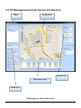
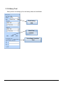
3.3 TR Management Center Screen Introduction
Menu
Google Map
Query Tool
Data Output Area
GPRS Tool
TR Management Center Main Screen
TR-151
page 24
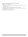
There are five parts of TR Management Center Screen as below.
The basic menu options
z
Menu:
z
GPRS Tools:
Shows the trackers' connection status, GPRS service status and the
tracker's latest location
Used for searching history data and finding coordinates
z
Query Tool:
z
Data Output Area: Shows the tracker login status, received GPRS data and query results
z
Google Map:
Shows the Google Map
The detailed description of each part is as following.
TR-151
page 25
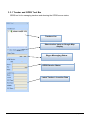
3.3.1 Tracker and GPRS Tool Bar
GPRS tool is for managing trackers and showing the GPRS server status
Trackers List
Show tracker trace on Google Map
display
Skype Messaging Status
GPRS Service Status
Latest Tracker’s Location Data
TR-151
page 26
3.3.2 Query Tool
Query tool is for looking up for the history data and coordinate.
Find history
data
Data Tool
buttons
Coordinate Location
Tool
TR-151
page 27
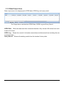
3.3.3 Data Output Area
Data output area is for displaying the GPRS data, GPRS log, and query result.
The Output area is divided into GPRS Data, GPRS Log and Query Result
GPRS Data: Shows the data sent from connected trackers. Only the last 100 entries from each
tracker are shown.
GPRS Log:
Shows the record of all tracker connections and disconnections including the raw
transmitted data.
Query Result: Shows all matching results from the trackers' history data.
TR-151
page 28
3.4 Skype Setup
In stead of sending SMS to trackers by mobile phones, TR Management Center sends SMS to
trackers by Skype. You can not only send SMS to trackers for asking report by Skype, but send
SMS to set the parameters of TR-151’s function.
In order to send SMS by Skype, please complete the following steps to activate the SMS function
of Skype.
Step 1: Install Skype Software
You can download Skype from www.skype.com or the website of the local Skype distributor.
Please refer to the instruction of Skype to install the software.
Note: The pictures and instructions provided in this manual are based on Skype version
3.6.1.xxx. If they do not match the version of Skype you are currently using, please download
and upgrade to the latest version from the Skype website.
Step 2: Please create a user account.
Once you have created an account, you can login and use Skype's basic functions.
Step 3: Buy Skype credit
TR-151
page 29
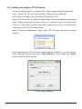
Step 4: Test the Skype SMS function
After completing the above process, please check if Skype's SMS functions can work by
sending a test message to mobile phone. Follow the SMS messaging procedure below to send a
SMS message and check that your Skype is working normally.
¾ Sending a test SMS
From the Skype menu, select "Tools" -> "Send SMS Message" then follow the steps
shown below
Choose Send SMS Message from the menu
TR-151
page 30
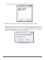
At the Send SMS interface, add the recipient's mobile phone number
Write the content of SMS and click Send SMS button
TR-151
page 31
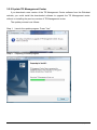
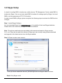
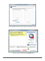
Step 5:
When you launch the TR Management Center program, the following security
verification pop-up window will appear in the lower right corner of the screen asking you to allow
the TR Management Center to use Skype functions.
Click the blue text to request Skype access.
Select "Allow this program to use Skype"
TR-151
page 32
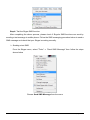
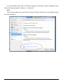
If you accidentally select "Do not allow this program to use Skype", please change this from
within the Skype program at "Options -> "Advanced"
Note:
The exact procedure may vary from the version of Skype. Please refer to the Skype manual
for more information.
TR-151
page 33
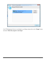
If the TR Management Center is not allowed to use Skype, please click on the "Change" button
and select "Allow this program to use Skype".
TR-151
page 34
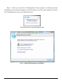
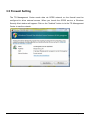
3.5 Firewall Setting
The TR Management Center sends data via GPRS network, so the firewall must be
configured to allow external access. When you launch the GPRS service, a Windows
Security Alert window will appear. Click on the "Unblock" button to let the TR Management
Center to use the network.
TR-151
page 35
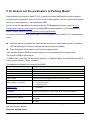
3.6 TR Management Center System Requirement
The computer system requirements of the TR Management Center program:
1. The computer must be equipped with at least an Intel Pentium 4 or equivalent AMD CPU,
256MB of RAM and a network card.
2. Supports the following operating systems: Windows XP, Windows 2000, Windows 2003
or Windows Vista. (It does not support 64 bits OS)
3. The graphics card must support at least 256 colors and a resolution of 800x600 or
higher.
4. Skype must be version 3.6 or higher. The latest version can be downloaded from
www.Skype.com.
5. A fixed IP address is required. If a dial-up network connection is used, the program must
be provided with this computer's external IP address. TR-151 trackers must be
configured with this IP.
3.7 Copyrights and Example Information
The copyright on all software and hardware mentioned in this manual belong to their
respective owners.
1.
The copyright of Windows XP, Windows 2000, Windows 2003 and Windows Vista
belong to the Microsoft Corporation.
2.
The copyright of the Skype program belongs to Skype Technologies S.A.
3.
The copyright of Google Map belongs to Google Inc.
4.
The copyright of Intel Pentium belongs to the Intel Corporation.
5.
The copyright of AMD belongs to Advanced Micro Devices, Inc.
All text and telephone numbers mentioned in this manual are used as an example only. We
apologize in advance for any coincidences.
Any copyrights not mentioned in this manual belong to their respective owners.
TR-151
page 36
4. TR-151 Management Operation
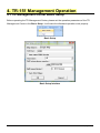
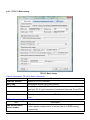
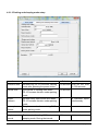
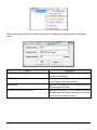
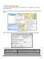
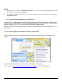
4.1 TR Management Center Basic Setup
Before operating the TR Management Center, please set the operation parameters of the TR
Management Center in the Basic Setup. It will make the afterward operation work properly.
Basic Setup
Basic Setup Interface
TR-151
page 37
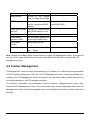
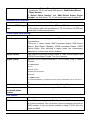
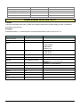
Item
Function
Map Source
Choose to use Google
Map or Google China Map
TCP Port
Set the communication
port for connecting GPRS
network
Description
The default is 5000. You can set
form1024~5000.
Auto start GPRS Choose to automatically
service
start GPRS service or not
Time Zone
Set the time zone
SMS Return
phone number
Set the phone number for
receiving the SMS report
SMS report
format
Set the SMS format
Auto Start Skype
Choose to automatically
start Skype
Note: Please do the Basic Setup for the first time of using TR Management Center. If you want to
use the China’s map, please choose Google China Map in the Map Source and re-start TR
Management Center.
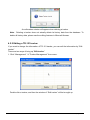
4.2 Tracker Management
TR Management Center can track and manage up to 5 trackers. You have to set the parameters
of TR-151 while adding a set of TR-151 in the TR Management Center. If you have already set 5
trackers in the TR Management Center and want to set one more tracker, please delete one of
the existing trackers in the TR management center.
The tracker’s information and parameters must be properly configured before using other
functions of TR Management Center. Then your tracker can correctly send report back to the TR
Management Center and that the program can correctly display the tracker's current location on
the map.
TR-151
page 38
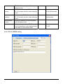
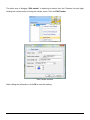
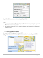
4.2.1 Adding and setting a TR-151 tracker
You can add a new tracker by making TR-151 Setup, please follow the steps below.
Step 1: Connect the TR-151 to the computer's USB port by the USB cable.
Step 2: Open the battery cover and adjust DIP Switch 3 to "On".
Step 3: Turn on the TR-151. When the status LED turns red, the tracker is under setup
mode. (Please hold down the power button for 2 seconds or more until the red light
comes on.) (Note: After turning on the power, please wait around 10 seconds before
continuing with the TR-151 setup process)
Step 4: From the "Management" menu, select "TR-151 Setup" and enter the setup
interface.
Step 5: After selecting "TR-151 Setup", please select the COM Port. If you are not sure
which COM port you are using, click "Scan COM Port". Then please click "Setup"
button to open the Setup window.
TR-151 Setup Interface
TR-151
page 39
Click on Scan COM Port to find the port the TR-151 is connected to
Note: If the scan fails to locate TR-151, please try again with the other USB port.
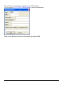
Note: If your SIM card asks for SIM PIN entry, a window will appear prompting you for the
PIN password. (Please make sure you enter the correct code as the SIM card will be locked
after three failed attempts. If you do not know the PIN code or the SIM card is locked, please
contact your GSM network service provider for assistance.)
SIM PIN Code Interface
TR-151
page 40
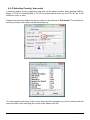
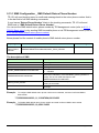
4.2.1.1 TR-151 Basic setup
TR-151 Basic setup
Tracker Information: TR-151's Basic Information:
Item
Description
Firmware Version
Version of TR-151 firmware.
IMEI Code
International Mobile Equipment Identity
Set Time Zone
On: SMS sent from TR-151 will be converted to local time. Off: SMS
sent from TR-151 will include the Coordinated Universal Time (UTC).
Tracker name
Enter the name of the tracker.
Phone number
Enter the phone number for this TR-151 and select the country/area
code.
SMS default return phone number:
Item
SMS default return
phone number
TR-151
Description
TR-151 will send location report or confirmed message back to the
return phone number that is in the last field of all SMS tracking
commands.
page 41
If user leaves “Return Phone Number” blank in the tracking
commands, TR-151 will send SMS back to “SMS Default Return
Phone Number”.
If “Return Phone Number” and “SMS Default Return Phone
Number” are both blank, TR-151 will send report back to caller ID.
Maximum GPS fixing time:
Item
Maximum GPS fixing
time
Description
The maximum time allowed for a GPS fix. If TR-151 cannot get fixed
of the location within the specified time, TR-151 will turn off GPS and
send back its last known position.
Default report mode setting:
Item
Description
Default report mode
TR-151 will automatically go into the "Default report mode" when it
is powered on.
There are 5 report modes: SMS Immediate Report, SMS Period
Report, Stop Report (Standby), GPRS Immediate Report, GPRS
Period Repot. After selecting a report mode, the unnecessary
parameters for that mode will be disabled.
Report interval
The interval of sending location report in "SMS Period Report" and
“GPRS Period Report” mode. The unit is second.
Report format
Set the TR-151's report format as 0, "TEXT Format" or as 1, "NMEA
Format".
0 – TEXT Format
TR-151
2008/3/6 18:50:6
N2459.8094,E12129.2499
GPS fixed"
1 – NMEA Format
?0,352023006488395,0,3,130308,061740,E12129.3241,N2459.8051,134.0,0.04,0.00,4,4.
45!
Number of reports
Set the number of reports to transmit in "Period Report" mode.
Return phone number
for default phone
number
The phone number for receiving the SMS of "Default report mode"
SOS number:
Item
Description
SOS number
After SOS button is pressed, TR-151 will send SMS with its location
to 3 phone numbers. You can set the 3 phone numbers in the field of
SOS number. If only one phone number is setup, TR-151 will only
send one SMS.
TR-151
page 42
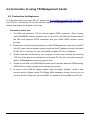
4.2.1.2 Parking and sleeping mode setup
Item
Description
Default
Remarks
Activation time
Set how long TR-151 will enter Parking
mode after pressing the power button.
30 seconds Can be set from
1~300 seconds
Interval time
The interval of sending SMS when
TR-151 senses vibration under parking
mode
30 seconds
Report
numbers
Set how many SMS will be sent when
TR-151 senses vibration under parking
mode
0
0 indicates report
continuously
Return phone
number
The phone number for receiving SMS
under parking mode
Regular report
interval
The interval of sending SMS under
sleeping mode. During the interval,
12 hours
Unit is in hours
TR-151
page 43
TR-151 will temporarily exit from
sleeping mode
Alarm report
interval
The interval of sending SMS when
TR-151 senses vibration under sleeping
mode
30 seconds Can be set from
5~86,400 seconds
Report
numbers
Set how many SMS will be sent when
TR-151 senses vibration under sleeping
mode
0
Return phone
number
The phone number for receiving SMS
under sleeping mode
Sensitivity
Set how many vibrations TR-151 senses
over this sensitivity under parking mode,
it will send out the location SMS
10
0 indicates report
continuously
Can be set from
1~255
4.2.1.3 TR-151 GPRS setting
TR-151
page 44
Item
Description
Remarks
GPRS Port
The communication port for
connecting to GPRS network
Default is 5000
Can be set from 5000~9999
GPRS APN
The name of your GPRS
service provider's access point
The APN depends on the SIM card
for the telecommunication service
provider used by your TR-151 (The
list below is for service providers in
Taiwan. Please contact the provider
for your region if necessary)
GPRS user name
GPRS user name
GPRS user password
GPRS user password
Contact your GSM/GPRS network
service provider
GPRS DNS1
GPRS DNS2
GPRS Server IP
address or Domain
name
GPRS server host IP
The fixed IP or Domain Name for the
computer running the TR
Management Center
APN Settings in Taiwan’s provided
Service Provider
APN
Far East one
fetnet01
Trans Asia Telecommunications
hank
Chunghwa Telecom
emome or internet
MOBITAI Communications
gprs1
Taiwan Mobile
Internet
KG Telecom
internet
Once you have entered all of the settings, click on "OK" to set up the TR-151 or click on "Cancel"
to cancel the setup.
Note 1: After setting up TR-151, if this tracker does not exist in the TR Management Center it will
be added to the database. If it already exists then the database will be updated.
Note 2: Once setup is complete, turn off the TR-151, set the DIP Switch to OFF and restart
before use.
Note 3: If your device has not been used for a long time or the data has been lost for some
reason, click on the "Default" button to reset the device to its default settings.
TR-151
page 45
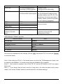
4.2.2 Tracker Management
Tracker Management is used to manage registered or previously configured trackers. In
Tracker Management, you can edit or delete trackers.
You can find Tracker Management from the Menu "Management" -> "Tracker Management".
The Tracker Management option under Management in Menu
Tracker Management interface
TR-151
page 46
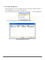
4.2.2 Deleting a TR-151 tracker
There are two ways for deleting TR-151 trackers in the TR Management Center
1. Select "Management" -> "Tracker Management" from menu bar.
Choose the TR-151 you want to delete, and then click on the "Delete" button.
2. The other way of deleting TR-151 tracker is selecting a tracker from the Trackers List and right
clicking the mouse button to bring the tracker menu. Now click on Delete Tracker to delete the
selected tracker.
Method 2 for deleting a tracker
TR-151
page 47
A confirmation window will appear when deleting a tracker
Note: Deleting a tracker does not actually delete its history data from the database. To
delete all history data, please use the editing features in Microsoft Access.
4.2.2 Editing a TR-151 tracker
If you want to change the information of TR-151 tracker, you can edit the information by “Edit
tracker”
There are two ways of bring up “Edit tracker”
1. Click “Management” Æ “Tracker Management” from menu.
Double click a tracker, and then the window of “Edit tracker” will be brought up.
TR-151
page 48
The other way of bringing “Edit tracker” is selecting a tracker from the Trackers List and right
clicking the mouse button to bring the tracker menu. Click on Edit Tracker
Edit Tracker window
After editing the information, click OK to save the setting.
TR-151
page 49
4.2.5 Selecting Country/ Area code
It requires adding country code/Area code prior to the phone number while sending SMS by
Skype to TR151 or sending SMS to TR-151 by mobile phone when you and TR-151 are in the
different country or area.
Please click the button beside the phone number in the window of “Edit tracker” The window for
selecting country code/ area code will be brought up.
You can press the first letter of the country name by the keyboard to go to the countries with the
same first letter. After selecting the country code, please click OK.
TR-151
page 50
4.3 Instruction of using TR Management Center
4.3.1 Instruction for Beginners
If it is the first time for you to use TR-151, please refer 4.2.1 Adding and setting TR-151 trackers
to set TR-151. It will ensure TR-151 can send the report to TR Management center via GPRS
network and display the location on the map.
Precautions before use:
1.
The SIM card installed in TR-151 should support GPRS connection. This is usually
what GSM/GPRS network operators refer to as a 2G or 3G SIM card. Please check if
the SIM card supports GPRS connection with your GSM/ GPRS network service
provider.
2. Please make sure the computer where you install TR Management center has a fixed IP.
If the PC uses a dial-up network, please check the float IP address should be the same
IP with TR-151’s setting. You can send a SMS to update TR-151's IP address.
3.
Please check that the firewall on your computer or router does not block the receiving
TCP Port. If this port is not unblocked in the firewall, TR-151 will not be able to send its
data to TR Management center through this port.
4.
Please consult with your GSM/GPRS network service provider about the GPRS setting,
GPRS will not connect properly if the settings are incorrect.
5.
In order to send SMS by Skype, please install the Skype software, create a user
account and buy Skype credits. The Skype SMS messaging function must be set up
correctly as well. Skype only can send SMS. It is unable to receive SMS from TR-151
TR-151
page 51
4.3.2 Receiving data from TR-151 via GPRS network
In order to receive report from TR-151 by TR Management Center, there is some setting should
be made.
Step 1: Activate GPRS service
Please set the GPRS port. (You can refer to 4.2.1.3 to set GPRS port.) After setting GPRS port,
please activate GPRS server
To activate the GPRS service, please click the "Start" button at GPRS Service. After activating
the GPRS service, the GPRS service status will be shown as the right screen below.
->
Step 2: Send command to connect TR-151 or wait TR-151 to connect to TR Management center
automatically.
Please refer 4.2.1.1 and check what the default report mode you set for TR-151 is. If the default
report mode of TR-151 is “GPRS immediate report” or “GPRS period report”, TR-151 will
automatically connect to TR Management center after it is powered on every time.
If the default report mode is “SMS immediate report” or “SMS period report” or “stop”, it requires
TR Management to send SMS by Skype to TR-151 to make GPRS connection with the TR
Management center.
Please select the TR-151 under Tracker list and right click the mouse to bring out the menu as
below..
Please select “Connect Tracker (Skype)” to ask TR-151 to make GPRS immediate report to TR
Management center.
Step 3: When TR-151 is making GPRS connection with TR Management center, you will see
TR-151 show the status on the tracker list as the screen below.
TR-151
page 52
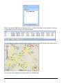
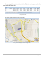
TR-151 will send a SMS with the content of OK to mobile phone and send the position report to
TR Management center shown as the picture below.
You can make the location of that position report to show on Google map by clicking that report.
You can also click Satellite to see the location on satellite map.
TR-151
page 53
Step 4: Send commands to TR-151 for asking report via GPRS network
Select a connected TR-151 and right click the mouse to bring up the option menu. You can click
“Send GPRS Command” to ask TR-151 to send position report to TR Management center.
Below please find the description of the option menu
Item
Description
Connect Tracker
Make the GPRS connection between this TR-151 and
TR Management center by sending SMS via Skype
Disconnect Tracker
Cut the GPRS connection between this TR-151 and TR
Management center
Send GPRS Command
Make commands to TR-151 for asking immediate report
or periodic report or stop report via GPRS network
Send Commmand (Skype)
Send commands by Skype’s SMS to ask TR-151 to
make the report or start voice monitoring
Setup Tracker (Skype)
Set the parameters of TR-151’s functions by Skype’s
SMS
Edit Tracker
Edit the basic information of this TR-151
Delete Tracker
Delete this TR-151 from tracker list
4.3.3 Send GPRS command to TR-151
Before sending GPRS commands to TR-151, please refer to 4.3.2 to make GPRS connection
between TR-151 and TR Management center.
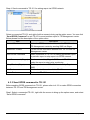
Step1: Select a connected TR-151, right click the mouse to bring up the option menu, and select
“Send GPRS command”
TR-151
page 54
After clicking Send GPRS Command, the window for selecting commands will be brought as
below.
Item
Description
GPRS Immediate Report
Ask the connected TR-151 to report its latest
position immediately.
GPRS Period Report
Ask the connected TR-151 to report according
to the Report interval periodically
Stop Report
Ask the connected TR-151 to disconnect from
TR Management center
Disconnect and Period Report
Ask the connected TR-151 to disconnect from
TR Management center and then periodically
according to the report interval
TR-151
page 55
4.4 TR Management Center Data Query
All the data sent from TR-151 will be stored in the database of TR Management center. You can
make this data show on Google map or export them into KML format.
4.4.1 Look up for history data
You can look up for the history data that TR-151 sent to TR Management center by Query Tool.
"Query Tool"
Item
Description
Tracker
Select the tracker whose history data you’d like to look up for
Type
To look up for the data according to the time of Tracker’s timer
(Tracker Time) or the receiving time of the PC (Local Time)
Start time
The start time of the period of looking up the history data
End Time
The end time of the period of looking up the history data
Find
Start to look up for the data
Export
Export the data into KML format
Delete
Delete query results
TR-151
page 56
After specifying all the queried conditions, click the Find button and the query results will be
shown on the Data Output Area..
Query Result list
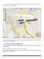
The results will also be shown on the Google Map.
Query results displayed on the Google Map
TR-151
page 57
If you select a piece of result under the Data Output Area, its location and corresponding details
will be shown on the Google Map.
If you click on one of the tracker icon on the Google map, the selected tracker’s data under Data
Output Area will be highlighted.
4.4.2 Export the data into KML format
You can export the queried data into KML format for others to show the data on the Google map
or Google earth.
Step 1: Please refer to 4.4.1 to look up for the history data.
Step 2: Please click the Export button on the Query Tool. And then enter a name for the exported
data in the field of File name.
TR-151
page 58
Enter a name for the exported KML file
4.4.3 Delete the history data in the database
You can delete the history data in the database.
Step 1: Select the name of the tracker and time interval whose data you’d like to delete.
Step 2: Click the Delete button.
TR-151
page 59
4.5 Send SMS by Skype to set TR-151
In 4.2.1 Adding and setting a TR-151, you can connect TR-151 with TR Management center by
the USB cable to set its parameters. You can also set its parameters by SMS via the Skype
software in the TR Management center.
For the requirement of sending SMS by Skype, please refer to 3.4 Skype setup.
4.5.1 Set Geo-fence
Geo-fence is that setting a rectangular or circular area as permissible area or restricted area.
When TR-151 gets out the permissible area or goes in to the restricted area, TR-151 will send its
location to the preset mobile phone number via SMS or to TR Management center via GPRS
network.
You can send SMS by Skype to make TR-151 enter SMS Geo-fence mode or GPRS Geo-fence
mode. The contents of SMS include choosing the rectangular or circular areas (Rectangle or
Circle) , getting in the restricted areas or getting out the permissible areas to send alarm (In
Geo-fence or Out Geo-fence) , time intervals of alarm report (Report interval), Number of
reports, and Report format.
TR-151 will start to get fixed of the location as soon as it enters Geo-fence mode. TR-151 will
keep fixing the location. Once TR-151 detect it enters restricted area or gets out the permissible
area, it will send its location to the preset mobile phone number via SMS or to TR Management
center via GPRS network.
TR-151
page 60
4.5.1.1 Set TR-151 to send Geo-fence location report to mobile phone
Step1: Select the tracker requires Geo-fence setting from Tracker List.
Step 2: Right click the tracker and select Setup Tracker (Skype) Æ SMS Geo-fence Setup
Step 3: Enter and select the parameters of Geo-fence SMS on the window of SMS Geo-fence
setup.
TR-151
page 61
You can refer to the table below for the meaning of the Geo-fence parameters.
Item
Description
Geofence Type
Choose to set a rectangular (Rectangle) or a circular
(Circle) area
Alarm Type
Choose to send location report when TR-151 gets in (In
Geofence) or get out (Out Geofence) the area
Report interval
The interval of sending location report when TR-151 disobey
Geo-fence rule
Number of reports
How many reports TR-151 will send when TR-151 disobey
Geo-fence rule
Report format
Choose the report format as NEMA format or text format
Upper Left coordinate
The coordinates of the Geofence's upper left corner
(Rectangle)
Bottom Right coordinate
The coordinates of the Geofence's lower right corner
(Rectangle)
Center point
The coordinates for the center of the Geofence (Circle)
Radius
Geofence radius (Circle)
Step 4: Click OK to send out the setting of Geo-fence to the TR-151 BY Skype’s SMS.
TR-151
page 62
A dialog window for informing that Skype has sent out the SMS will appear. You can operate the
other functions during the process of sending SMS.
NOTE: In addition to enter the coordinates to set the Geo-fence, you can also draw a rectangular
or circular area on the Google map to set the Geo-fence.
Draw a rectangular area on the Google map to set Geo-fence:
Step 1: Select Rectangle in the field of Geo-fence type.
Step 2: Click the Add from Google Map button
Step3: Click and drag the mouse to draw a rectangle as the Geo-fence range on the Google map.
The coordinates of the upper left corner and bottom right corner will be automatically loaded to
the field of coordinate.
Drawing the rectangular area with the mouse
TR-151
page 63
Loads the coordinates into the coordinate fields
Draw a circular area on the Google map to set Geo-fence:
Step 1: Select Circle in the field of Geo-fence type.
Step 2: Click the Add from Google Map button
Step 3: Left click on one point of the Google map as the central point of the circle. A balloon icon
will appear. Drag the mouse to the position of the other side of the radius, and then left click the
mouse. The circle will be shown on the Google map. And the coordinate of the central point and
the radius will be automatically loaded into the fields.
TR-151
page 64
Clicking on the center and moving the cursor will make a line appear
The system loads the center coordinates and radius into the coordinate fields
TR-151
page 65
4.5.1.2 Set TR-151 to send Geo-fence location report to TR Management center
Step1: Select the tracker requires Geo-fence setting from Tracker List.
Step 2: Right click the tracker and select Setup Tracker (Skype) Æ GPRS Geo-fence Setup
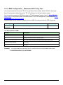
Step 3: Enter and select the parameters of Geo-fence GPRS on the window of GPRS Geo-fence
setup.
TR-151
page 66
Step 4: Click OK to send out the setting of Geo-fence to the TR-151 BY Skype’s SMS.
You can refer to 4.5.1.1 to set the coordinates of Geo-fence by drawing rectangles or circles on
the Google map.
TR-151
page 67
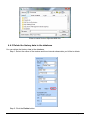
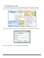
4.5.2 Set the SMS default return phone number
You can enable or disable the SMS default return phone number and assign the phone number
as the default for receiving return SMS.
Step 1: Select the TR-151 and right click to select Setup Tracker (Skype) Æ SMS Return Number
Setting.
Step 2: Choose to Enable or Disable the SMS default return phone number. If you select to
enable the SMS default return phone number, please enter the phone number.
Step 3: Click OK button to send out the setting by Skype’s SMS.
TR-151
page 68
4.5.3 Set the Maximum GPS Fixing Time
You can set a period of time for TR-151 to get fixed of the location. When TR-151 cannot get
fixed of the location within the period, TR-151 will send out the last location report.
Step 1: Select the TR-151 and right click to select Setup Tracker (Skype) Æ Maximum GPS
fixing time
Step 2: Enter the value for Maximum GPS fixing time.
Step 3: Click OK button to send out the setting by Skype’s SMS.
TR-151
page 69
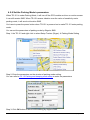
4.5.4 Set default report mode
You can set the default report mode for TR-151. When TR-151 is powered on, it will enter the
default report mode.
Step 1: Select the TR-151 and right click to select Setup Tracker (Skype) Æ Default Report Mode
Setting
Default report mode menu
Step 2: Select the default report mode, report format, and enter the concerning parameters.
You can refer tot the table below to enter the parameters.
Item
Description
Default report mode
Select the report mode after TR-151 is powered on
Report format
Select NEMA format or text format
Default return phone number
Enter the phone number for receiving SMS of default
TR-151
page 70
report mode
Report interval
Enter the interval between 2 reports
Number of reports
Enter how many reports will be sent out in the default
report mode
Step 3: Click OK button to send out the setting by Skype’s SMS.
TR-151
page 71
4.5.5 Set SOS phone number
You can set the phone number for receiving emergency report after SOS button is pressed.
Step 1: the TR-151 and right click to select Setup Tracker (Skype) Æ SOS Number Setting
Step 2: Enter the phone number for receiving emergency report after SOS button is pressed.
Step 3: Click OK button to send out the setting by Skype’s SMS.
TR-151
page 72
4.5.6 Set the Parking Mode’s parameters
When TR-151 is under Parking Mode, it will turn off the GPS module and turn on motion sensor.
It can still receive SMS. When TR-151 senses vibration over the value of sensitivity under
parking mode, it will send out location SMS.
You have to press the power button when TR-151 is powered on to make TR-151 enter parking
mode.
You can set the parameters of parking mode by Skype’s SMS.
Step 1: the TR-151 and right click to select Setup Tracker (Skype) Æ Parking Mode Setting
Step 2: Enter the parameters on the window of parking mode setting.
You can refer to 4.2.1.2 Parking and sleeping mode setup to enter the parameters
Step 3: Click OK button to send out the setting by Skype’s SMS
TR-151
page 73
NOTE:
1. If you enter 0 in the field of Number of reports, TR-151 will not stop sending the report until
TR-151 does not sense the vibration.
2. The Sensitivity is that while TR-151 senses the vibration over the sensitivity, it will send out
the position report.
4.5.7 Set the Sleeping Mode’s parameters
When TR-151 is under sleeping mode, its GSM module and GPS module will be turned off, the
motion sensor will be turned on. Just like being under parking mode, it will send out SMS while it
senses vibration. But TR-151 will not receive SMS under sleeping mode.
Making TR-151 to enter sleeping mode, you have to adjust DIP switch 4 to ON when TR-151 is
powered off.
You can set the parameters of sleeping mode by Skype’s SMS.
Step 1: Select the TR-151 and right click to select Setup Tracker (Skype) Æ Sleeping Mode
Setting
Step 2: Enter the parameters on the window of sleeping mode setting.
You can refer to 4.2.1.2 Parking and sleeping mode setup to enter the parameters
TR-151
page 74
Step 3: Click OK button to send out the setting by Skype’s SMS
NOTE:
1. If you enter 0 in the field of Number of reports, TR-151 will not stop sending the report until
TR-151 does not sense the vibration.
2. The Sensitivity is that while TR-151 senses the vibration over the sensitivity, it will send out
the position report.
4.5.8 Set the GPRS parameters
You can set the GPRS parameters by Skype’s SMS.
Step 1: Step 1: Select the TR-151 and right click to select Setup Tracker (Skype) Æ GPRS
Setting
TR-151
page 75
Step 2: Enter the parameters on the window of GPRS setting.
You can refer to 4.2.1.3 TR-151 GPRS setting to enter the parameters
Step 3: Click OK button to send out the setting by Skype’s SMS
TR-151
page 76
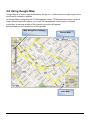
4.6 Using Google Map
Google Map is an online map developed by Google Inc. It offers access to major maps of the
world and is constantly updated.
As Google Map is integrated into TR Management center, TR Management center can work
under Internet connected status. If you start TR Management center under no Internet
connection, a warning window of No Internet connection will appear.
Below please see the introduction of Google Map
Map Navigation Controls
Change Map
Index Map
TR-151
page 77
4.6.1 Google map data
Google Map includes the basic map, satellite map, hybrid map and other map data.
You can switch the map by the buttons on the upper right corner of Google map.
Basic Map
TR-151
page 78
Satellite Map
Hybrid Map
TR-151
page 79
4.6.2 Google map operation
Move the map: You can move the map by right clicking and dragging the map. Or you can move
the map by the tool
on the Google map.
Zoom the map: You can zoom in or zoom out the map by scrolling forward or backward the
mouse. Or you can zoom in or out the map by the tool
TR-151
page 80
5. Operating the TR-151
5.1 How to set SOS number of TR-151 by SMS?
Users can set SOS number of TR-151 by sending SMS via mobile phone or by TR
Management’s Skype (Please refer to 4.5.5 Set SOS phone number).
The format of SMS by mobile phone is following as:
?7,IMEI,4,SOS1,SOS2,SOS3,Return_Phone_Number!
The table below explains the content of the SMS.
Format
Description
?
Start sign
7
Function code
IMEI
IMEI code of the TR-151
4
Setting code of SOS number
SOS1, SOS2, SOS3
The phone number for receiving SOS message
Return_Phone_Number
The phone number for TR-151 to send an SMS to inform the setting is
OK.
!
End sign
Example 1, if user only wants to set 1 set of SOS, and return phone number as 616123456, you
can send SMS as:
?7,355632000166323,4,616123456,,,626123456!
(You still have to add 2 commas after the set of SOS.)
Example 2, if user wants to set SOS1, SOS2, SOS3, and return phone number as 616123456,
717123456, 818123456, and 626123456, you can send the SMS as.
?7,355632000166323,4,616123456,717123456,818123456,626123456!
NOTE: You can also set SOS number by management center. Please refer to page 18 for the
detail.
TR-151
page 81
5.2 How to set TR-151 to immediately report its position by
SMS?
Users can send an SMS by mobile phone or by TR Management center’s Skype to ask TR-151
to immediately report its position.
The format of SMS by mobile phone is following as:
?0,IMEI,Report_Format,Return_Phone_Number!
The table below explains the content of the SMS.
Format
Description
?
Start sign
0
Function code
IMEI
IMEI code of the TR-151
Report_Format
0 or 1. 0 is for end user, and 1 is for SMS management center
development
Return_Phone_Number
The phone number for receiving the reporting SMS.
!
End sign
TR-151 will send an SMS whose format is “?0,IMEI,OK!” to the return phone number to confirm it
has received the request. And then it will start to get fixed the position. After getting fixed the
position, it will send SMS with its location to the return phone number.
For example: If you’d like to ask TR-151 to send immediate report in format0 to 626-123456.
You have to enter ?0, 355632000166323,0,626123456!
And then you will get ?0,355632000166323,OK!. After TR-151 get fixed of the position, you will
get the position report like Position report
Name
2008/12/15 10:20:39
N2459.8915,E12129.2186
GPS fixed
NOTE:
If TR-151 can not get fixed the position within the “Maximum GPS Fixing Time”, it will return the
previous location. When the GPS position is fixed, it will again return the position data.
Please refer to page 18 to set “Maximum GPS Fixing Time.”
TR-151
page 82
5.3 How to set TR-151 to periodically report its position by
SMS?
Users can send an SMS by mobile phone or by TR Management center’s Skype to ask TR-151
to periodically report its position.
The format of SMS by mobile phone is as below.
?1,IMEI,Report_Interval,Number_of_Reports,Report_Format,Return_Phone_Number!
The table below explains the content of the SMS.
Format
Description
?
Start sign
1
Function code
IMEI
IMEI code of the TR-151
Report_Interval
Set the interval between two reporting SMS
Number_of_Reports
Set how many reporting SMS should be sent
Report_Format
0 or 1. 0 is for end user, and 1 is for SMS management center
development
Return_Phone_Number
The phone number for receiving the reporting SMS.
!
End sign
TR-151 will send an SMS whose format is “?1,IMEI,OK!” to the return phone number to confirm it
has received the request. And then TR-151 will send the SMS with its location to the return
phone number according to the report interval.
NOTE:
If user sets the number of reports as 0, TR-151 will keeps sending the periodical report until user
send the SMS of ?2,IMEI,Return_Phone_Number! to stop the periodical report.
Example 1:
Require continuous 120-sec period report in format0 sent to 626123456
You have to enter “? 1,355632000166323,120,0,0,626123456!”
TR-151 will send “? 1,355632000166323,OK!” And then you will get the position report like
Position report
Name
2008/12/15 10:20:39
N2459.8915,E12129.2186
GPS fixed
TR-151 will send position report every 120 seconds until you stop periodical report.
Stop periodical report:
Users can send an SMS to stop periodical report.
The format of SMS is following as?2,IMEI,Return_Phone_Number!
TR-151
page 83
5.4 How to set TR-151 to immediately make report its
position via GPRS network?
Users can send an SMS by mobile phone or by TR Management center’s Skype ( to ask TR-151
to immediately report its position via GPRS network to TR-151 Management center or GPRS
server.
The format of SMS by mobile phone is following as:
?8,IMEI,Return_Phone_Number!
The table below explains the content of the SMS.
The description of SMS
Format
Description
?8
Start sign and function code
IMEI
IMEI of TR-151
Return_Phone_Number
The phone number for receiving OK message.
!
End sign
TR-151 will send an SMS whose format is “?8,IMEI,OK!” to the return phone number to confirm it
has received the request. And then it will start to get fixed the position. After getting fixed the
position, it will send its location to the TR-151 Management center or GPRS server.
Example: Require GPRS immediate report sent to 626-123456
You have to enter “?8,355632000166323,626123456!”
And then you will get “? 8,355632000166323,OK!”
TR-151
page 84
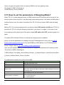
5.5 How to set TR-151 to periodically report its position via
GPRS network?
Users can send an SMS by mobile phone or by TR Management center’s Skype to ask TR-151
to periodically report its position via GPRS network to GPRS server (TR Management center).
The format of SMS by mobile phone is as below.
?9,IMEI,Report_Interval,Return_Phone_Number!
The description of SMS
Format
Description
?9
Start sign and function code
IMEI
IMEI of TR-151
Report_Interval
Time interval of sending data report. The unit is second.
Return_Phone_Number
The phone number for receiving OK message.
!
End sign
TR-151 will send an SMS whose format is“?9,IMEI,OK!” to the return phone number to confirm it
has received the request. Then it will periodically send the periodical report according to the
report interval.
Example 1:
Require 120-sec period report sent to 626123456
You have to enter “?9,355632000166323,120,626123456!
Example 2:
Require 180-sec period report sent to 626123456
?9,355632000166323,180,626123456!
Stop GPRS periodical report:
Users can send an SMS to stop periodical report.
The format of SMS is following as:
?2,IMEI,Return_Phone_Number!
TR-151
page 85
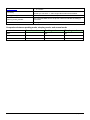
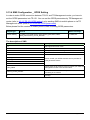
5.6 Tracking/Monitoring TR-151 by GPRS
Users can make commands to TR-151 for asking immediate report, periodical report, or stop
report via GPRS server and network.
Report type
Format
Note
Example
TR-151 will
return
0 Immediate report $0,IMEI!
*note1
$0,355632000166323!
$OK!
1 Period report
*note2
$1,355632000166323,30!
$OK!
sec= 5~86400
Report every 30 seconds
*note3
$2,355632000166323!
2 Stop connect
$1,IMEI,sec!
$2,IMEI!
$OK!
*note1: When TR-151 receives this command, it will send the report back immediately. It will send only one time,
and the GPRS connection is still on.
*note2: When TR-151 receives this command, it will send back the report every specified second. And the GPRS
connection is still on. The time error of return could be 1~3 seconds, or larger if the GPRS connection is not stable.
*note3: When TR-151 receives this command, it will disconnect from GRPS and go to standby mode.
TR-151
page 86
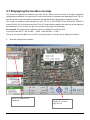
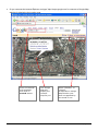
5.7 Displaying the location on map
The format of longitudes and latitudes got from TR-151 differs from the format of Google map/earth’s
longitudes and latitudes. So users have to convert the format of longitudes and latitudes got from TR-151
into the format Google map/earth’s longitudes and latitudes before displaying the location on map.
The format of longitudes and latitudes got from TR-151 is like E2459.79 and N12129.26. E2459.79
means E24°59.79’. N12129.26 means N121°29.26’ Please take the digits at the right side of the degree to
be divided by 60. The number you get is the number at the right side of decimal.
For example, the longitudes and latitudes got from is E2459.79 and N12129.26
You have to take 59.79 ÷ 60 =0.9965
; 29.26 ÷ 60=0.487666 ≒ 0.4877
Then you can enter 24.9965 and 121.4877 into Google earth or Google map to display the location.
●
Start the Google Earth software.
Input the latitude and
longitude
TR-151
The Google Earth will
display the location
map for you.
page 87
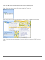
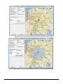
● Or you can start the Internet Explorer and type "http://maps.google.com" to connect to Google Map
website for displaying the location map.
Enter the latitude
and longitude
and click on
Search button.
TR-151
The Google
Map will
display the
location
map for you.
Select "Satellite" or
"Hybrid".
It depends on Google
Map whether your
area is supported by
this mode or not.
page 88
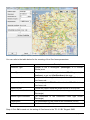
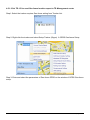
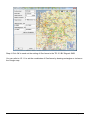
5.8 How to set TR-151 enter Geofence mode?
Users can send SMS by mobile phone or by TR Management center’s Skype (refer to 4.5.1 Set
Geo-fence) to TR-151 for setting up to 10 permissible or restricted areas whose shape is circular
or rectangular for tracking the vehicles or monitoring the equipment/assets. Users can choose to
receive alarm message while TR-151 enters the restricted areas or to receive alarm message
while TR-151 gets out the permissible areas. The content of the SMS includes the rectangular or
circular areas defined by longitudes and latitudes, getting in the restricted areas or getting out the
permissible areas to send alarm, time intervals of alarm report, number of reports, report format
and return phone number.
The format of SMS by mobile phone is as below.
Report type
Format
Return message
4 SMS Geofence
?4,IMEI,{[R,longitude,latitude,longitude,latitude],
[C,longitude,latitude,radius(meter)]},In_or_Out,
Report_Interval,Number_of_Reports,Report_Format,
Return_Phone_Number!
?4,IMEI,OK!
GPRS
11
Geofence
?11,IMEI,{[R,longitude,latitude,longitude,latitude],
[C,longitude,latitude,radius(meter)]},In_or_Out,
Report_Interval,Number_of_Reports,Report_Format,
Return_Phone_Number!
?11,IMEI,OK!
The description of SMS
Format
Description
?4
?11
Start sign and function code
?4 Æ Send location info to mobile phone.
?11 Æ Send location info to TR-151 management center
IMEI
IMEI of TR-151
{[R,longitude,latitude,longitude,latitude],[C,lo
ngitude,latitude,
radius(meter)]}
Boundary information:
R: rectangular shape Æ Follow by two longitudes, latitudes.
C: circular shape Æ Follow by one longitude, latitude and one
radius.
In_or_Out
In_or_Out=in
Æ Send alarm message if TR-151 gets in the
restricted areas.
In_or_Out=out
Æ Send alarm message if TR-151 gets out
the permissible areas.
Report_Interval
Time interval of sending data report. The unit is second.
Set how many reports will be sent?
Number_of_Reports
Number_of_Reports=0 Æ continuous report
Number_of_Reports=X Æ X times report
Report_Format
Set TR-151 to return message by Format0 or Format1.
(see description below)
Return_Phone_Number
?4: The phone number for receiving return message and alarm
message.
?11:The phone number for receiving return message
TR-151
page 89
!
End sign
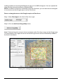
Note 1:
The format of Google map/earth’s longitudes and latitudes differs from the format of TR-151’s.
So please convert the format of Google map/earth’s longitudes and latitudes into the format of
TR-151’s longitudes and latitudes before setting Geofence.
If you get a set of latitude and longitude from Google earth like 24°59’47.40” & 121°29’15.72”,
you have to convert the format to TR-151 format as below and then set geo-fence.
47.40 ÷60=0.79 15.72÷60=0.262
Please take E 12129. & 262 N2459.79 to set geo-fence
If you get a set of latitude and longitude from Google earth like 24.9965°& 121.4877°, you have
to convert the format to TR-150 format as below and then set geo-fence.
0.9965 x60=59.79 0.4877 x60=29.262
Please take E12129. 262 & N2459.79 to set geo-fence
Note 2:
User can set up to 10 rectangular or circular boundaries. Each SMS contains one boundary setting.
User can send numerous SMS to complete one set of settings, including numerous rectangular or
circular boundaries. For example, if user wants to set the boundary includes 2 rectangles and 1 circle.
User has to send 3 SMS, two with rectangle information, one with circle information.
SMS1:
?4,IMEI,R,longitude,latitude,longitude,latitude,In_or_Out,Report_Interval,
Number_of_Reports,Report_Format,Return_Phone_Number!
SMS2:
?4,IMEI,R,longitude,latitude,longitude,latitude,In_or_Out,Report_Interval,
Number_of_Reports,Report_Format,Return_Phone_Number!
SMS3:
?4,IMEI,C,longitude,latitude,radius,In_or_Out,Report_Interval,
Number_of_Reports,Report_Format,Return_Phone_Number!
If user uses numerous SMS in one setting, the IMEI, In_or_Out, Report_Interval, Number_of_Reports,
Report_Format, Return_Phone_Number must be the same between each SMS. If above parameters
are not the same between SMS, TR-151 only follows last SMS.
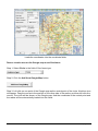
Note 3
In Boundary information
TR-151
page 90
{[R,longitude,latitude,longitude,latitude],[C,longitude,latitude,radius],}
User can set
R: rectangular follows by two longitudes and two latitudes.
Or
C: circular follows by one longitude, one latitude and one radius.
Example:
Rectangle
R,E12128.1883,N2342.8117,E12129.2186,N2459.8915
Example:
Circle (radius is 1000 meters)
C,E12129.2186,N2459.8915,1000
Note 4:
Example:
Send one SMS to setup Geofence.
Boundary includes one rectangle (two longitudes and two latitudes Æ
E12128.1883,N2342.8117,E12129.2186,N2459.8915)
When TR-151 gets out boundary, it would send format1, 10 times, 120 sec interval, alarm message
to 626123456.
?4,355632000166323,R,E12128.1883,N2342.8117,E12129.2186,N2459.8915,out,120,10,1,616123456!
Example:
Send three SMS to setup Geofence.
Boundary includes one rectangle (two longitudes and two latitudes Æ
E12128.1883,N2342.8117,E12129.2186,N2459.8915) and two circles (one longitude/latitude is
E12228.1883,N2442.8117, and radius is 1000 meter ) ( the other longitude/latitude is
E12328.1883,N2452.8117, and radius is 1500 meter)
When TR-151 gets out boundary, it would send format1, 10 times, 120 sec interval, alarm message
to 626123456.
SMS1:
?4,355632000166323,R,E12128.1883,N2342.8117,E12129.2186,N2459.8915,out,120,10,1,616123456!
SMS2:
?4,355632000166323,C,E12228.1883,N2442.8117,1000,out,120,10,1,616123456!
SMS3:
?4,355632000166323,C,E12328.1883,N2542.8117,1500,out,120,10,1,616123456!
Exit Geofence mode:
Users can send an SMS exit Geofence mode.
The format of SMS is following as:
?2,IMEI,Return_Phone_Number!
Caution:
If you exit Geofence mode, all the settings will be deleted.
TR-151
page 91
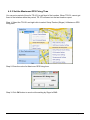
5.9 How to make TR-151 do Voice monitor function?
User can send a SMS by a mobile phone or by TR Management’s Skype to ask TR-151 start the
voice monitoring.
The format of SMS is following as:
?6,IMEI,Return_Phone_Number!
The table below explains the content of the SMS
Format
Description
?
Start sign
6
Function code
IMEI
IMEI code of the TR-151
Return_Phone_Number
The phone number for TR-151 to call back and transmit the sounds.
!
End sign
Note: If return phone number is empty, TR-151 will call back to Caller ID
TR-151 will send an SMS whose format is“?6,IMEI,OK!” to the return phone number to confirm it
has received the request. And then it will start to call back to the returned number written in the
SMS. And then user can listen to the sound or voice around TR-151.
Example:
User send voice command and make TR-151 call back to 626123456
?6,355632000166323,626123456!
Stop voice monitoring:
Users can hang up the phone call to stop voice monitoring.
TR-151
page 92
5.10. How to set the parameters of Parking Mode?
Parking Mode is for users to make TR-151 to send out location SMS while it senses vibration
over the value of sensitivity. When TR-151 is under Parking Mode, it will turn off the GPS module
and turn on motion sensor. It can still receive SMS.
Users can set the parameters of parking mode by TR Management Center (refer to 4.2.1.2
Parking and sleeping mode setup) or by send SMS by mobile phone or by TR Management
center’s Skype (refer to 4.5.6 Set parking mode’s parameters)
You have to press the power button when TR-151 is powered on to make TR-151 enter parking
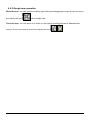
mode.
While the device is powered on, press the power button to enter parking mode. The status
LED will flash specific times to indicate the parking mode is enabled.
Press the power button again to exit from the parking mode.
User can also send an SMS by a mobile phone to set the parameters of parking mode.
The format of SMS is following as:
?7,IMEI,5,Park_Time,Park_Interval,Park_Number_of_Reports,Report_format,Sensitivity,Park_R
eturn_Number,Return_Phone_Number!
The table below explains the content of the SMS
Format
Description
?7
Start sign and function code
IMEI
IMEI of TR-151
5
Setting code for Parking setting
Park_Time
Set the active time for entering parking mode. The unit is second.
Park_Interval
Time interval of sending data report. The unit is second.
Park_Number_of_Reports
Report format
Set how many report will be sent.
0 Æ continuous report
X Æ X times report
0 Æ Format0
1 Æ Format1
Sensitivity
Set the number of vibration which enables TR-151 to send out alarm. The
number you can set is 1~255. Larger value means less sensitive.
Park_Return_Number
Return phone number for default report mode.
Return_Phone_Number
The confirmed SMS sent to the phone number to indicate the setting is
successful.
!
End sign
TR-151 will send an SMS whose format is“?7,IMEI,OK!” to the return phone number to confirm it
has received the request.
Exit from parking mode:
TR-151
page 93
Users can press the power button or send an SMS to exit from parking mode.
The format of SMS is following as:
?2,IMEI,Return_Phone_Number!
5.11 How to set the parameters of Sleeping Mode?
When TR-151 is under sleeping mode, its GSM module and GPS module will be turned off, the
motion sensor will be turned on. Just like being under parking mode, it will send out SMS while it
senses vibration over the value of sensitivity. But TR-151 will not receive SMS under sleeping
mode.
Making TR-151 to enter sleeping mode, you have to adjust DIP switch 4 to ON when TR-151 is
powered off. TR-151 will enter sleeping mode when you power it on again. If you want to exit
from sleeping mode, please turn off the power, adjust DIP switch 4 to OFF, and then power it on
again.
The status LED will flash 60 times to indicate the sleeping mode is enabled.
Users can set the parameters of sleeping mode by TR Management Center (refer to 4.2.1.2
Parking and sleeping mode setup) or by send SMS by mobile phone or by TR Management
center’s Skype (refer to 4.5.7 Set sleeping mode’s parameters)
User can also send an SMS by a mobile phone to configure the parameters of sleeping mode.
The format of SMS is following as:
7,IMEI,6,Sleep_Time,Sleep_Interval,Sleep_Number_of_Reports,Report_format,Sensitivity,Slee
p_Return_Number,Return_Phone_Number!
The table below explains the content of the SMS
Format
Description
?7
Start sign and function code
IMEI
IMEI of TR-151
6
Setting code for Sleeping setting
Sleep_Time
Sleep_Interval
Sleep_Number_of_Reports
TR-151
Set the time length of sleep mode. The unit is hour. When it reaches the
Sleep Time, TR-151 will wake up and send a SMS message, then go back
to Sleeping mode.
Time interval of sending data report when TR-151 senses the vibration
under sleeping mode. The unit is second.
Set how many report will be sent.
0 Æ continuous report
X Æ X times report
page 94
0 Æ Format0
1 Æ Format1
Set the number of vibration which enables TR-151 to send out alarm. The
number you can set is 1~255. Larger value means less sensitive.
Report format
Sensitivity
Sleep_Return_Number
Return phone number for default report mode.
Return_Phone_Number
The confirmed SMS sent to the phone number to indicate the setting is
successful.
!
End sign
Comparison between parking mode, sleeping mode, and normal mode
Function/Mode
Normal mode
GPS
Parking mode
Sleeping mode
Off
Off
GSM
On
On
Off
Motion sensor
Off
On
On
TR-151
page 95
5.12 The return format from TR-151
Return SMS format from TR-151
The data format is configurable in the SMS tracking commands. There are two types of the data
format as below.
Format0 is for general end users who send SMS commands to TR-151 by their cell phone or
PDA phone. This format is very easy to read by end users.
Format1 is specifically read by software TR Management Center that is developed by service
provider.
Data Report Format:
Report_Format=0 Æ Format0
Report_Format=1 Æ Format1
Format0:
Example:
Position report
Name
Time Date
GPS position
Fix or not
Position report
Name
2006/9/15 10:20:39
N2459.8915,E12129.2186
GPS fixed
Format1:
?IMEI,Status,GPS_Fix,Date,Time,Longitude,Latitude,Altitude,Speed,
Heading,Number_of_Satellites_In_Use,HDOP!
Example:
?353857014816785,2,3,280807,035825,E12129.2616,N2459.7918,97.2,0.13,142.31,04,2.4!
The description of Format1
Format
Value
Note
?
?
Command Head
IMEI
The number of IMEI
Status
Date
0
1
2
4
5
12
13
14
1
2
3
ddmmyy
Time
hhmmss
Longitude
(E or W)dddmm.mmmm
Example:
E12129.2186 Æ E 121°29.2186’
Latitude
(N or S)ddmm.mmmm
Example:
N2459.8915 Æ N 24°59.8915’
Altitude
xxxxx.x
unit: meters
GPS_Fix
TR-151
0: Immediate report
1: Period report
2: Stop report
4: Geo-fence
5: SOS
12: Parking
13: Sleeping
14: Battery Low
1: Fix not available
2: GPS 2D Fix
3: GPS 3D Fix
page 96
Speed
xxxxx.xx
Heading
ddd
Number_of_Satellites_In_Use
xx
HDOP
x.x
!
!
unit: knots (1knots = 1.852km)
Command End
Format of return GPRS from TR-151
Format:
Command_Head,IMEI,status,GPS_fix,date,time,longitude,latitude,altitude,speed,heading,number of satellites in
use,HDOP,Command_End
Example:
$355632000166323,1,1,040202,093633,E12129.2252,N2459.8891,00161,0.0100,147,07,2.4!
Format
Value
Command_Head
$
IMEI
(The number of IMEI)
Status
0
1
2
4
5
1
2
3
GPS_fix
Note
0: Immediate report
1: Period report
2: Stop connect
4: Geo-fence
5: Battery Low
1: Fix not available
2: GPS 2D Fix
3: GPS 3D Fix
date
ddmmyy
time
hhmmss
longitude
(E or W)dddmm.mmmm
latitude
(N or S)ddmm.mmmm
altitude
xxxxx.x
unit: meters
speed
xxxxx.xx
unit: knots (1knots = 1.852km)
heading
ddd
number of satellites in use
xx
HDOP
x,x
Command END
!
TR-151
Example:
E12129.2186 → E 121°29.2186’
Example:
N2459.8915 →N 24°59.8915’
page 97
5.13 SMS Configuration
User can configure following parameters into TR-151 by SMS. There are seven settings as
below.
z SMS Default Return Phone Number
z Maximum GPS Fixing Time
z Default Report Mode Setting
z SOS Numbers (Please refer to 5.1 How to set SOS number of TR-151 by SMS?)
z Parking setting
z Sleeping setting
z GPRS setting
Report type
Format
Return message
SMS Default
Return Phone
Number
?7,IMEI,1,Enable_SMSDefaultReturnPhoneNumber,
SMSDefaultReturnPhoneNumber,Return_Phone_Number!
?7,IMEI,OK!
Maximum GPS
Fixing Time
?7,IMEI,2,Maximum_GPS_Fixing_Time,
?7,IMEI,OK!
Default Report
Mode Setting
?7,IMEI,3,Default_Report_Mode,Report_Interval,
Number_of_Reports,Report_Format,
ReturnPhoneNnumberForDefaultReportMode,
Return_Phone_Number!
?7,IMEI,OK!
SOS Numbers
?7,IMEI,4,SOS1,SOS2,SOS3,Return_Phone_Number!
?7,IMEI,OK!
Parking Setting
?7,IMEI,5,Park_Time,Park_Interval,
Park_Number_of_Reports,Report_Format,sensitivity,
Park_Return_Number,Return_Phone_Number!
?7,IMEI,OK!
Sleeping
Setting
?7,IMEI,6,Sleep_Time,Sleep_Interval,
Sleep_Number_of_Reports,Report_Format,sensitivity,
Sleep_Return_Number,Return_Phone_Number!
?7,IMEI,OK!
GPRS Setting
?7,IMEI,7,Port,APN,GPRS_Name,GPRS_pwd,DNS1,DNS2,
Host_Name,Return_Phone_Number!
?7,IMEI,OK!
Return_Phone_Number!
Default_Report_Mode:
Default_Report_Mode = 0 Æ immediate report
Default_Report_Mode = 1 Æ period report
Default_Report_Mode = 2 Æ stop
Enable_SMSDefaultReturnPhoneNumber:
Enable or disable SMS Default Return Phone Number.
Enable_SMSDefaultReturnPhoneNumber = 0 Æ Disable
Enable_SMSDefaultReturnPhoneNumber = 1 Æ Enable
Maximum_GPS_Fixing_Time:
If GPS is not fixed within the time, it returns previous location and close GPS.
The unit is minute.
Number_of_Reports:
Set how many report will be sent.
Number_of_Reports = 0 Æ continuous report
Number_of_Reports = X Æ X times report
Report_Format: Ask TR-151 to return message by Format0 or Format1.
Report_Interval: Time interval of sending data report. The unit is second.
TR-151
page 98
Return_Phone_Number: TR-151 will send confirmed message back to this Return_Phone_Number.
If user let Return_Phone_Number be empty, TR-151 will send report back to
SMSDefaultReturnPhoneNumber.
If Return_Phone_Number and SMSDefaultReturnPhoneNumber are both empty, TR-151 will
send report back to caller ID.
ReturnPhoneNnumberForDefaultReportMode: Return phone number for default report mode. TR-151 will send
report to this number after it is turned on when Default Report Mode is set to immediate
report or period report.
SMSDefaultReturnPhoneNumber: Set SMS Default Return Phone Number.
TR-151
page 99
5.13.1 SMS Configuration _ SMS Default Return Phone Number
TR-151 will send location report or confirmed message back to the return phone number that is
in the last field of all SMS tracking commands.
If user leaves “Return Phone Number” blank in the tracking commands, TR-151 will send
SMS back to “SMS Default Return Phone Number”.
You can set the SMS default return phone number by TR Management center (refer to 4.2.1.1
TR-151 Basic setup) or by sending SMS via mobile phone or via TR Management center (refer to
4.5.2 Set the SMS default return phone number)
Below please find the content of mobile phone’s SMS default return phone number
Report type
Format
Return message
SMS Default
Return Phone
Number
?7,IMEI,1,Enable_SMSDefaultReturnPhoneNumber,
SMSDefaultReturnPhoneNumber,Return_Phone_Number!
?7,IMEI,OK!
The description of SMS
Format
Description
?7
Start sign and function code
IMEI
IMEI of TR-151
1
Setting code for SMS Default Return Phone Number
0 Æ Disable
1 Æ Enable
In the SMS tracking commands (immediate report, period report,
stop report, Geofence), if the field Return_Phone_Number is
empty, TR-151 will send data report to this
SMSDefaultReturnPhoneNumber.
Enable_SMSDefaultReturnPhoneNumber
SMSDefaultReturnPhoneNumber
Return_Phone_Number
The confirmed SMS sent to the phone number to indicate the
setting is successful.
!
End sign
Example:
To configure SMS default return phone number as 313-987654, and send confirmed SMS to
626-123456.
?7,355632000166323,1,1,313987654,626123456!
Example: To Disable SMS default return phone number and send confirmed SMS to 626-123456.
?7,355632000166323,1,0,,626123456!
TR-151
page 100
5.13.2 SMS Configuration _ Maximum GPS Fixing Time
You can set a period of time for TR-151 to get fixed of the location. When TR-151 cannot get
fixed of the location within the period, TR-151 will send out the last location report.
You can set the maximum GPS fixing time by TR Management center (refer to 4.2.1.1 TR-151
Basic setup) or by sending SMS via mobile phone or via TR Management center (refer to 4.5.3
Set the Maximum GPS fixing time)
Below please find the content of mobile phone’s SMS for setting maximum GPS fixing time
Report type
Format
Return message
Maximum GPS
fixing time
?7,IMEI,2,Maximum_GPS_Fixing_Time,Return_Phone_Number!
?7,IMEI,OK!
The description of SMS
Format
Description
?7
Start sign and function code
IMEI
IMEI of TR-151
2
Setting code for Maximum GPS fixing time
The time that allows for GPS fixing. If GPS fixing is not achieved within the
time, it will close GPS and send back the previous location info.
Maximum_GPS_Fixing_Time
Return_Phone_Number
The confirmed SMS sent to the phone number to indicate the setting is
successful.
!
End sign
Example: To configure Maximum GPS fixing time to 5 minutes and send confirmed SMS to 626-123456.
?7,355632000166323,2,5,626123456!
TR-151
page 101
5.13.3 SMS Configuration _ Default Report Mode Setting
You can set the default report mode for TR-151. When TR-151 is powered on, it will enter the
default report mode. You can set the default report mode by TR Management center (refer to
4.2.1.1 TR-151 Basic setup) or by sending SMS via mobile phone or via TR Management center
(refer to 4.5.4 Set default report mode)
Below please find the content of mobile phone’s SMS for setting default report mode
Report type
Format
Return message
Default report
mode setting
?7,IMEI,3,Default_Report_Mode,Report_Interval,
Number_of_Reports,Report_Format,
ReturnPhoneNnumberForDefaultReportMode,
Return_Phone_Number!
?7,IMEI,OK!
The description of SMS
Format
Description
?7
Start sign and function code
IMEI
IMEI of TR-151
3
Setting code for Default report mode setting
Default_Report_Mode
0
1
2
8
9
Report_Interval
Time interval of sending data report. The unit is second.
Number_of_Reports
Report_Format
Æ SMS immediate report
Æ SMS periodical report
Æ stop
Æ GPRS immediate report
Æ GPRS periodical report
Set how many report will be sent.
0 Æ continuous report
X Æ X times report
0 Æ Format0
1 Æ Format1
ReturnPhoneNnumberForDefaultReportMode
Return phone number for default report mode.
Return_Phone_Number
The confirmed SMS sent to the phone number to indicate
the setting is successful.
!
End sign
Note:
The configuration is for default report mode (SMS Immediate, SMS Period, Stop, GPRS immediate, GPRS
periodical) settings. In immediate and stop settings, some fields are unnecessary, please leave these fields empty
and separate them by a comma. Please see following examples for detail.
Example:
SMS Immediate report. Configure default report mode as SMS immediate report, send format1
report data to 313-987654, and send confirmed SMS to 626-123456.
?7,355632000166323,3,0,,,1,313987654,626123456!
Example:
SMS Period report. Configure default report mode as SMS period report, send 10 times, 180-sec
period report in format0 to 313-987654, and send confirmed SMS to 626-123456.
TR-151
page 102
?7,355632000166323,3,1,180,10,0,313987654,626123456!
Example: Stop. Configure default report mode as stop (standby), and send confirmed SMS to 626-123456.
?7,355632000166323,3,2,,,,,626123456!
Example:
GPRS Period report. Configure default report mode as GPRS period report, send 180-sec period
report, and send confirmed SMS to 626-123456.
?7,355632000166323,3,9,180,,,,626123456!
TR-151
page 103
5.13.4 SMS Configuration _ GPRS Setting
In order to make GPRS connection between TR-151 and TR Management center, you have to
set the GPRS parameters into TR-151. You can set the GPRS parameters by TR Management
center (refer to 4.2.1.3 TR-151 GPRS setting) or by sending SMS via mobile phone or via TR
Management center (refer to 4.5.8 Set the GPRS parameters)
Below please find the content of mobile phone’s SMS for setting GPRS parameters.
Report type
Format
Return message
GPRS Setting
?7,IMEI,7,Port,APN,GPRS_Name,GPRS_pwd,DNS1,DNS2,
Host_Name,Return_Phone_Number!
?7,IMEI,OK!
The description of SMS
Format
Description
?7
Start sign and function code
IMEI
IMEI of TR-151
7
Setting code for GPRS setting
Port
GPRS Port of the Server
APN
GPRS_Name
GPRS_pwd
DNS1
Please consult your GPRS network service provider for
these parameter values.
DNS2
Host_Name
Please enter the physical IP of the PC where you install TR
Management center or the domain name.
Return_Phone_Number
The confirmed SMS sent to the phone number to indicate
the setting is successful.
!
End sign
TR-151
page 104