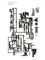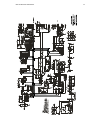
1
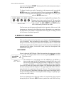
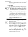
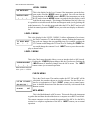
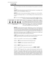
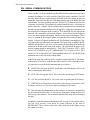
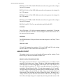
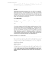
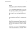
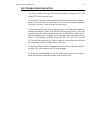
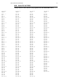
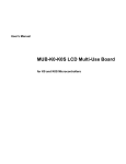
OPERATIONS AND REPAIR MANUAL
MODEL REM 500
NEUTRON SURVEY METER
INCLUDES SECTION ON MCA OPTION
September 1998
Revision A
The REM-500 contains a small check source. Please read the section on
Radioactive material.
health physics instruments
330 D South Kellogg Ave, Goleta, CA 93117 Tel 1-805-967-8422
REM 500 INSTRUCTION MANUAL
TABLE OF CONTENTS
SPECIFICATIONS . . . . . . . . . . . . . . . . . . . . . . . . . . . . . . . . . ii
I. INTRODUCTION . . . . . . . . . . . . . . . . . . . . . . . . . . . . . . . . . 1
II. GETTING STARTED . . . . . . . . . . . . . . . . . . . . . . . . . . . . . . 1
III. MODES OF OPERATION. . . . . . . . . . . . . . . . . . . . . . . . . . . . 2
IV. CHANGE MODE . . . . . . . . . . . . . . . . . . . . . . . . . . . . . . . . 3
V. BUTTONS . . . . . . . . . . . . . . . . . . . . . . . . . . . . . . . . . . . . 5
VI. OVERFLOW, AND HIGH RADIATION LEVELS . . . . . . . . . . . . . . 6
VII. SHOCK . . . . . . . . . . . . . . . . . . . . . . . . . . . . . . . . . . . . . 7
VIII. LOW BATTERY . . . . . . . . . . . . . . . . . . . . . . . . . . . . . . . . 7
IX. BATTERY REPLACEMENT . . . . . . . . . . . . . . . . . . . . . . . . . . 7
X. FAILURE . . . . . . . . . . . . . . . . . . . . . . . . . . . . . . . . . . . . . 8
XI. STATISTICS AND COUNTS . . . . . . . . . . . . . . . . . . . . . . . . . . 8
XII. CHECK MODE. . . . . . . . . . . . . . . . . . . . . . . . . . . . . . . . . 8
XIII. MULTICHANNEL ANALYZER MODE. . . . . . . . . . . . . . . . . . . 9
XIV. SERIAL COMMUNICATIONS . . . . . . . . . . . . . . . . . . . . . . . 10
XV. PRINCIPAL OF OPERATION . . . . . . . . . . . . . . . . . . . . . . . . 11
1. ELECTRONICS/SOFTWARE. . . . . . . . . . . . . . . . 11
2. DETECTOR . . . . . . . . . . . . . . . . . . . . . . . . . 12
XVI. CALIBRATION MODE . . . . . . . . . . . . . . . . . . . . . . . . . . . 13
XVII. CALIBRATING THE INSTRUMENT . . . . . . . . . . . . . . . . . . . 16
XVIII. RADIOACTIVE MATERIAL INSIDE DETECTOR . . . . . . . . . . . 18
XIX. MAINTENANCE MODE . . . . . . . . . . . . . . . . . . . . . . . . . . 19
XX. CIRCUIT DESCRIPTION . . . . . . . . . . . . . . . . . . . . . . . . . . 20
XXI. ELECTRONIC ADJUSTMENTS . . . . . . . . . . . . . . . . . . . . . . 23
XXII. TROUBLE SHOOTING NOTES . . . . . . . . . . . . . . . . . . . . . . 25
XXIII. QUALITY FACTORS . . . . . . . . . . . . . . . . . . . . . . . . . . . 26
XXIV. PARTS LIST . . . . . . . . . . . . . . . . . . . . . . . . . . . . . . . . 27
XXV. PARTS LOCATION AND SCHEMATICS . . . . . . . . . . . . . . . . 31
i
REM 500 INSTRUCTION MANUAL
ii
SPECIFICATIONS
MECHANICAL
Size: 12"L x 4.5"W x 4.5"H excluding handle, handle extends height to 6.25".
Weight: 5 lbs, 2 oz including alkaline batteries.
External Controls: 5 pushbutton switches for POWER ON/OFF, MODE, ALTERNATE, RESET and LIGHT.
Internal Controls: Cal and Reset pushbutton;Coarse Contrast, Pole Zero, High
Voltage, and LLD trimpots.
DETECTOR
Type: Sealed Spherical TE Proportional Counter. Rossi Type. 2 1/4" ID.
Wall Material: A150 Conducting Tissue Equivalent plastic.
Wall Thickness: 0.12 cm, 144 mg/cm, Aluminum can .065"
Filling Gas: Propane gas, 2 micron
Internal Source: Less than 1 uCi Cm244
OPERATIONAL
Readout: Alphanumeric 2 line x 16 character LCD
Range: Autoranging from .001 mREM/h to 999 REM/h and .001 mRAD/h to 999
RAD/h rate and .001 mREM to 999 REM and .001 mRAD to 999 RAD integrate.
SI units of Sv and Gy are also selectable.
Multi-Channel Analyzer: 256 Channel MCA. 65535 counts/channel. RS-232 serial link can control MCA operation.
Temperature Dependence: less than ± 15 % from 15 to 45°C
Humidity Response: Less than 10 % change from 0 to 95 % RH non condensing.
Neutron Energy Response: 70 KeV to 20 MeV
Gamma Response: Less than 1% at 1 RAD/h.
Warm Up Time: 15 seconds
Battery Life: 100 hours; 6 ea alkaline C cells.
Serial RS232 link: In Rate and Integrate mode, sends radiation level on command. In MCA mode dumps MCA raw channel data, count time, total counts and
Instrument Calibration Factor. Baud rate is 9600. Available if the MCA option is
installed.
REM 500 INSTRUCTION MANUAL
iii
PLEASE NOTE:
All of the descriptions and examples throughout the manual use the units of Rem
and Rad. Si units of Sv and Gy are also available. To select the Si units please refer to the Calibration section.
This manual covers the REM-500 with or without the MCA option. To check if
the MCA option is installed, look on the front panel. If the panel contains a jack
on the lower right for a connector, then the MCA option has been installed.
REM 500 INSTRUCTION MANUAL
1
I. INTRODUCTION
The Rem 500 is a Neutron Survey Meter that reads in both REM and RADS. It is a
small light portable instrument that is at home both in the field and in the lab. This
manual describes its operation and use.
II. GETTING STARTED
The instrument is very easy to use. There are only 5 controls across the top of the
instrument. All of the controls are push buttons. To turn the instrument on,
REM 500
10
push the ON/OFF button. The instrument will first do a self test and wait
SELF TEST
until it stabilizes. The countdown shows how much longer to wait and also
shows that the instrument is functioning.
TURN ON DISPLAY
When the instrument is finished with the opening display, it goes into normal operation. It may show a small amount of radiation on the first display. You
will notice in the upper right hand corner a countdown of seconds. When it gets to
zero it displays the next reading and then recycles. The lower left of the display
shows the time constant, in seconds. The lower right shows the number of counts
acquired during the time constant period.
.000 mREM/h
9
10sec TC
0ct
Changing from REM to RAD is very easy, just push the ALT button. Each
time it is pressed it changes from RAD to REM or from
ON/OFF MODE ALT RESET LIGHT REM to RAD. It just alternates back and forth between
the two.
FRONT PANEL
If you are having difficulty seeing the display because
you are in dim light, pushing the LIGHT button will turn
on the display backlight for 15 seconds.
To freeze the display, push the RESET button. The word
HOLD will appear in the upper right hand corner of the display. The reading is
REM 500 INSTRUCTION MANUAL
2
now frozen. Pushing the RESET button again will reset the instrument and put it
back into normal operation.
To change from the rate mode of operation, to the integrate mode, just push the
MODE button twice. To get back to the RATE mode, again push the MODE button twice. Switching back and forth between rate and integrate is very easy, just
push the MODE button twice.
ON/OFF MODE ALT RESET LIGHT
FRONT PANEL
The integrate mode has a slightly different display. The
Integrate time is shown on the lower left. The counts that
have been acquired remain on the lower right. The upper
right is blank. The ALT, RESET, and LIGHT buttons
work in this mode just like the rate mode.
You have now run the instrument through its basic operation. More areas of the
instrument are discussed in the following sections. Remember you cannot hurt
the instrument if you push the wrong button at the wrong time. Turning it on and
off will restore it to normal operation.
III. MODES OF OPERATION
There are three main modes of operation, rate, integrate, and Multichannel Analyzer (if installed). Rate and integrate are discussed here. See the Multichannel
Analyzer section for a description of that mode. In addition there is a Check mode
which is discussed in the Check Mode section. Each mode can be identified by the
arrangement of the display. See the MCA mode section for a description of the
Multichannel Analyzer.
RATE MODE
.000 mREM/h
10sec TC
Figure 1 shows the RATE display. When first turned on, the instruments is in this
mode. The integrate mode can be reached by pushing MODE twice from
9
the Rate mode.
0ct
The radiation level, autoranging from .001 mREM/h to 999 REM/h, is
shown on the upper left. If the instrument is reading RADS, then it will
show between .001 mRAD/h and 999 RAD/h. It indicates over range by
showing >1K REM/h (or >1K RAD/h if reading in RADS) in the display.
The lower left shows the current time constant. The instrument gathers data for
the time constant period then displays it. The upper right hand corner of the display shows the time remaining in this period. There are 3 Time Constant settings;
10, 30, or 60 seconds. The number in the upper right corner of the display shows
the time remaining in this time constant period. Each reading is completely separate from any other reading.
FIGURE # 1
RATE DISPLAY
The lower right hand corner shows the number of events that have been counted
during this period. When the HOLD button is pushed the word HOLD will ap-
REM 500 INSTRUCTION MANUAL
3
pear in the upper right corner of the display. If the battery is bad, the word LBAT
will flash in the same place.
INTEGRATE MODE
Figure 2 shows the Integrate display. The Integrate display can be reached by
pushing MODE twice from the RATE display. The display is updated ev.000 mREM
ery 10 seconds. The radiation level, autoranging from .001 mREM to 999
00:00:10
0ct
REM, is shown on the upper left. If the instrument is reading RADS, then
it will show between .001 mRAD and 999 RAD. It indicates over range by
FIGURE # 2
showing 1K REM (or 1K RAD if reading in RADS) in the display.
INTEGRATE DISPLAY
The lower left shows the time of integration. It displays the time in
HRS:MIN:SEC and will go as high as 18 hrs, 12 min and 15 seconds before it resets to zero. It updates every second. The lower right hand corner shows the number of events that have been counted. When the HOLD button is pushed, the
instrument recalculates the level for that second then updates the display and
shows HOLD in the upper right hand corner. Switching between REM and RAD,
when on hold, using the ALT button, will show the two levels. If the battery is
bad, the word LBAT will flash in the upper right hand corner.
The instrument will continue to gather data until it is reset.
IV. CHANGE MODE
The change mode allows adjustment of the display contrast and time constant; it
is also a way into the Check mode.
↓NEXT
Soft Keys are
shown with an
arrow.
There are five levels of displays that can be shown besides the rate and integrate
displays. We have named them level 1, level 2, level 3, check and MCA. You may
have noticed level 1 when you switched between the rate and integrate modes. On
these displays the meaning of the keys are changed. The new meaning is shown
on the display with arrows pointing to the corresponding key. The keys that are redefined in all except the MCA mode are the three middle keys. The LIGHT key
is not changed except in the MCA mode. The ON/OFF key is not changed.
The five levels are shown below. To get to level 1 push the MODE key once. To
get to level 2 just push the ↓NEXT key. To get to level 3 just push the ↓NEXT key
again, and to get back to normal operation, just push the ↓NEXT key again. If
you are in the Check display, pushing ↓NEXT will get you back to normal operation. The same is also true for the MCA mode. Pushing the ↓NEXT key repeatedly will always get you back to normal operation.
REM 500 INSTRUCTION MANUAL
4
LEVEL 1 MENU
INT RATE NEXT
This is the display for the Level 1 menu if the instrument was in the Integrate mode when the MODE button was pushed. You will note that the
RATE INT NEXT
new definition of the MODE button is RATE. If the instrument was in the
↓
↓
↓
RATE mode when the MODE button was pushed, then the display would
look like the next example. This change of definition of the key is the way
it is possible to switch between the Rate and Integrate mode just by pushing the
mode button twice. To exit this menu push either the INT or RATE and you will
be back in normal operation. ↓NEXT moves you to the next display as shown below.
LEVEL 2 MENU
This is the display for the LEVEL 2 MENU. It allows adjustment of two items,
the Time Constant or TC and the display contrast. Pushing the buttons unTC DISPL NEXT
der each one changes the corresponding item. For example, pushing the
10↓
↓
↓
↓TC button would change the TC from 10 to 30. Pushing the ↓DISPL button would change the contrast 1 level. ↓NEXT moves you to the next display as shown below.
LEVEL 3 MENU
This is the Check menu that only allows you to go into the check or MCA mode.
Pushing the ↓CHECK button changes into the Check menu. Pushing the
CHECK MCA NEXT
↓MCA button (if installed) changes into the MCA menu. The ↓NEXT
↓
↓
↓
button returns you to normal operation.
MCA will show only if the
MCA option is installed.
CHECK MENU
LFT PK
RT NEXT
080 090 100 ↓
00:00:00
0CT
This is the Check menu. The numbers under the LFT, PK and RT will be
calculated, the numbers shown are just for reference. See the Check section for an explanation of Check. ↓NEXT returns you to normal operation. A detailed discussion of the function of each key is discussed in the
Buttons section.
MCA MENU
This is the Multichannel or MCA menu. This mode allows the instrument
to gather data and then download the data to a computer on an RS232 serial link.
The remote computer can also control the operation of the MCA. See the MCA
section for a complete explanation of the MCA. ↓NEXT returns you to normal
operation.
REM 500 INSTRUCTION MANUAL
5
V. BUTTONS
There are 5 buttons on the front of the instrument. There operation is described
below.
ON/OFF Turns the instrument on and off. If the instrument is on, pushing it will
turn it off. If it is off, pushing it will turn it on.
MODE Selects the various modes and displays. Pushing it twice will switch between rate and integrate and vice a versa. Pushing it once will enter the menu of
Level 1.
ALT ALT is for ALTERNATE which selects between REM and RAD. If the instrument is reading in REM pushing the ALT will switch
ON/OFF MODE ALT RESET LIGHT to RAD. If the instrument is reading in RAD, pushing it
will change to REM. When in the Rate mode, switching
between REM and RAD will reset the data even if the instrument is on hold. This is not true for the Integrate
FRONT PANEL
range. If the instrument is on hold, then switching between RAD and REM will not reset the data.
RESET Puts the instrument in either a Hold mode, or resets it. The first push of
the button holds the data. The display will show HOLD in the upper right hand
corner to let you know that the instrument is in hold. Pushing the button again will
reset the instrument and it will resume normal operation. If the instrument is on
HOLD and in the integrate range, the ALT button will change between RAD and
REM on the same data without resetting the instrument.
LIGHT Turns on the light for 16 seconds. If you are in the various menu’s, pushing the light will keep it on until you go back to normal operation.
NOTE: To reach LEVEL 1 from normal operation push MODE.
LEVEL 1 ↓INT Puts the instrument into the Integrate mode.
LEVEL 1 ↓RATE Puts the instrument into the Rate mode.
LEVEL 1↓NEXT Changes from level 1 to level 2
NOTE: To reach LEVEL 2 from normal operation push MODE, ↓NEXT.
LEVEL 2 ↓TC Changes the Time constant of the instrument for the Rate mode.
Each time it is pressed it changes to the next time constant. There are three time
constants, 10, 30 and 60 seconds. This is the time the instrument will gather data
before presenting it on the screen. The upper right hand corner of the rate display
will show the time remaining in this time constant, i.e. before updating. The instrument will remember the time constant when it is turned off. The next time it is
REM 500 INSTRUCTION MANUAL
6
turned on it will have the same time constant. If it is set to 60 seconds and turned
off, the next time it is turned on it will still be 60 seconds.
LEVEL 2 ↓DISPL Changes the contrast of the display. There are 12 levels of
contrast. Each push of the ↓DISPL button will change the contrast by one level.
When the contrast reaches the maximum it jumps to the minimum. Just keep
pushing the button until the contrast looks correct. When the instrument is turned
off, it remembers the contrast setting.
LEVEL 2 ↓NEXT Changes from level 2 to level 3
NOTE: To reach LEVEL 3 from normal operation push MODE, ↓NEXT,
↓NEXT.
LEVEL 3 ↓CHECK Turns on the check source and checks for the peak channel
number from this operation. See section on Check.
LEVEL 3 ↓NEXT Changes from level 3 to normal operation.
NOTE: To reach Check from normal operation push MODE, ↓NEXT, ↓NEXT,
↓CHECK.
CHECK ↓NEXT Changes to normal operation, same as level 3 ↓NEXT.
NOTE: To reach MCA from normal operation push MODE, ↓NEXT, ↓NEXT,
↓MCA.
MCA ↓NEXT Changes to normal operation, same as level 3 ↓NEXT.
VI. OVERFLOW, AND HIGH RADIATION LEVELS
High level radiation (over 100 REM/h or 10 RAD/h) may give poor results. This
depends on the average quality factor of the radiation. The instrument does not
have any dead time correction and consequently, while the software is capable of
going up to 999 REM/h, the detector and electronics may not be. The dead time
associated with each pulse is about 60 µS. The instrument works by acquiring
each pulse, measuring its height, and then adding one to one of the 256 channels
that correspond to its height. It is a classic multichannel analyzer. Every 10 seconds the instrument calculates the raw REM and RAD data and resets all 256
channels to zero and starts acquiring the data again.
There are several problems with this approach. The first is that each channel can
only store 65536 counts. The second is that the higher channels contribute much
more to the radiation level than do the lower channels, because of their higher
quality factor. Channel 10 has a quality factor of 3.2, while channel 230 has a
quality factor of 24.8. The RAD ranges have no quality factor. These three items,
REM 500 INSTRUCTION MANUAL
7
dead time, maximum counts/channel, and different quality factors lead us to several guidelines:
1. At 10,000 counts in 10 seconds, the instrument will loose 1% of the counts and
response will start to fall off above this amount.
3. If the REM/h range is overrange, then suspect the RAD/h range has dead time
losses.
4. If you have to use the instrument in high radiation levels, then correct for dead
time losses.
VII. SHOCK
The instrument has some sensitivity to shock. Banging the case or the detector
could result in spurious counts. A sharp rap on the detector with a pencil will indeed produce spurious counts. Just hold the instrument with the handle and don’t
bang it against anything while making measurements.
VIII. LOW BATTERY
When first turned on the instrument turns on the light and checks the status of the
battery. If it has less than 10 hours remaining, it will show LOW BATTERY in the
display. If the batteries are too poor to turn the instrument on the display will remain dim.
During normal operation the instrument continually checks the status of the batteries. If it sees that there are only 10 hours remaining, then the instrument will
flash LBAT in the upper right hand corner of the display every 13 seconds. This is
only in the RATE and INTEGRATE modes, it will not show low battery in
LEVEL 1, 2, 3 or CHECK. In the MCA mode the upper right corner will flash
when the batteries are low.
The light uses the most power. If the batteries just check good, turning on the light
may make them check bad. This is the reason the instrument, when first turned on,
checks the batteries with the light on. When the batteries are low it is a good idea
not to use the light.
IX. BATTERY REPLACEMENT
The Rem 500 uses 6 C cells, either carbon zinc or alkaline. The alkaline will of
course last longer. The current drain is less than 40 mA with the light off.
To change the batteries remove the four screws on the end of the case that hold on
the small cover. The batteries should fall out. Use the sticker on the inside of the
REM 500 INSTRUCTION MANUAL
8
box as a guideline for inserting them. The batteries on the left hand side go in caps
first, and those on the right go in with their caps out. Do not ship the instrument
with batteries because it may turn on in shipment.
X. FAILURE
The instrument self checks itself at turn on. If it detects a failure it will display
FAILURE in the display. If this occurs the instrument cannot be used. See the
Maintenance Mode section for repair procedures.
XI. STATISTICS AND COUNTS
The display shows the number of counts that the instrument has received for that
reading in the lower right hand corner. For valid statistics the number of counts is
important. To achieve a reasonable accurate reading the number of counts needs
to be at least 10. It should preferably be around 100 and for more accurate analysis
it should be around 1000. This is the reason for the different time constants. In
high radiation areas the time constant may be any setting but the lower TC of 10
sec would probably be sufficient if the counts are high enough. Obviously as the
radiation level decreases the time constant should be increased to 30 or 60 sec onds to give more time to accumulate counts to obtain better statistics. The integrate range can be used for any radiation level but it is really ideal when looking at
very low levels.
XII. CHECK MODE
The Check mode of operation is used to determine the quality of the detector, and
to check the operation of the instrument. It can be used as an operational check. To
get in to the Check mode from normal operation push MODE, ↓NEXT, ↓NEXT,
↓CHECK.
LFT PK
RT NEXT
080 090 100 ↓
Inside the detector is a small Curium alpha source. When in the Check
mode the curium source radiates a small stream of alphas across the center
of the detector. These events simulate a neutron event in channel 90 of the
instrument.
In the Check mode, the instrument operates as a multichannel analyzer and displays the peak (PK) channel number as well as the left (LFT) and right (RT) half
max channel numbers. It updates the display every second. Pushing the ALT button will reset the MCA data and restart the acquisition. If the display remains on
channel 0 or 1 this indicates that the instrument is not functioning properly. Try
tapping on the side of the detector to free the shutter that shields the alpha source.
The peak channel indicates the calibration of the instrument, and the left and right
half max channels indicate the quality of the detector. The peak should be within
REM 500 INSTRUCTION MANUAL
9
15 channels of 90. Each channel away from 90 is an error of about 1.5% if the Calibration Factor remains unchanged. If it is out of this range, then the high voltage
needs to be adjusted as described in the Calibration Mode section VI. The spread
of the channels (RIGHT-LEFT) should be no more than 50 channels. If the spread
is more than this then the detector needs to be returned to the factory for refilling.
Leave this mode by pushing ↓NEXT. If the rate display reads a high number after
leaving Check mode, then the magnet actuated shutter that shields the alpha
source may be stuck. Just tapping the side of the detector should free the shutter.
There is also an additional Check mode in the Multichannel Analyzer section that
allows dumping all the channels. See that section for a description of the Check
mode.
XIII. MULTICHANNEL ANALYZER MODE
This mode is only available if the MCA option has been installed. Figure 3 shows
the Multichannel Analyzer (MCA) display. The MCA mode can be reached by
pushing MODE ↓NEXT ↓NEXT ↓MCA from the Rate display. This display is
continually updated. The upper left shows the time that the MCA has been running. It displays the time in HRS:MIN:SEC and will go as high as 18 hrs, 12 min,
15 seconds before it rolls over to zero and continues to count up again. The
00:00:00
0CT
upper right corner shows the number of events that have been counted the
CK NEXT RST RUN
same as in the integrate range. The buttons are relabeled with the names
Figure 3 MCA is stopped. shown in the display. The abbreviations are: ↓CK stands for CHECK and
Right button is marked
turns on and off the source inside the detector. Push it once to turn on the
RUN.
source. Push it again and the source will turn off. If the MCA is not running then there is no visual indication that the source is on or off. ↓NEXT
00:00:00
0CT
will return to normal rate display. RST Resets the MCA by clearing all the
CK NEXT RST STP
channels, time and counts. ↓RUN and ↓STP are the same button. When
MCA is running. Note
the MCA is stopped the button says ↓RUN indicating that pushing it will
how right button has
start it running. If the MCA is running, the button says ↓STP indicating
changed to STP
that pushing it will stop it.
All of these operations are duplicated in the RS-232 serial link. See the following section on SERIAL COMMUNICATIONS section for more details on
this link.
REM 500 INSTRUCTION MANUAL
10
XIV. SERIAL COMMUNICATIONS
There is an RS-232 Serial link built into the REM-500 for communications with a
terminal or computer. It is only available if the MCA mode is installed. The link
not only allows the user remote control of the MCA but also dumps the data on
command. One end of the RS-232 Cable plugs into the top of the REM-500 next
to the handle. The other end plugs into the 25 pin RS-232 COM port of a Personal
Computer or a terminal. The computer or terminal should be set to: 9600 baud, no
parity, 8 data bits, 1 stop bit. The serial link allows communications with both the
normal rate and integrate displays and with the MCA. When the instrument is in
the normal rate or integrate mode sending a T to the REM-500 will turn on the
data link. The instrument will respond with an * and will send out the radiation
level every time it updates the display. The level is the same as the display. This is
every 10 seconds in the integrate mode, and when the time reaches 0 in the rate
display. To turn it off, turn the instrument off. The data that is transmitted is 5 digits of radiation level followed by an exponent. The basic units are uREM, uRAD,
uREM/h and uRAD/h or nSv, nGy, nSv/h and nGy/h depending on the mode the
instrument is in and are the same as the display. The exponent is the power of 10
that the reading should be multiplied by. Thus 12567 0 would be 12567 x 10E0
which is 12567 uREM/h or 12.567 mREM/h and 67785 3 would be 67785 x 10E3
which is 67785 x 1000 which is 67785000 uREM/h which is 67.785 REM/h if the
instrument was in the rate mode reading REM.
In the MCA mode the serial link allows complete control of the MCA. The instrument must be in the MCA mode for this link to function. The commands are single characters except for the D command and are as follows:
R RESET This will reset the MCA and all data, time and channels. This is the
same as pushing the RST button.
S STOP This will stop the MCA. This is the same as pushing the STP button.
G GO This will start the MCA. This is the same as pushing the RUN button.
C CHECK This will turn on the check source in the detector if the source is off,
and turn it off if it is on. This is the same as pushing the CK button.
D This will dump the channel data on the serial port. A character is needed after
the D to actually send the data, i.e. it needs two characters to dump the data, a D
followed by any character. The instrument automatically stops before dumping
the data.
In addition, when the instrument is running in MCA mode, it will send the following line every second: 6 hex digits of counts followed by the time in
HR:MIN:SEC. These values are the same values as shown on the display except
the counts are in hex.
REM 500 INSTRUCTION MANUAL
11
DATA DUMP OF CHANNELS
Sending a D followed by another character when the instrument is in the MCA
mode will dump the data from the channels. The Data record is as follows:
256 lines of 5 digits. This is the counts for each channel. The counts are from 0 to
65534. 65535 is the maximum count even if the counts are more than this. There
is no overflow indication other that keeping the count at the maximum value. The
next is a line of counts and time. The counts are in HEX and are the total counts of
all channels. This is 6 hex digits. The time is in HR:MIN:SEC. This line is the
same as sent every second when the MCA is running.
XV. PRINCIPAL OF OPERATION
The Instrument is basically a 256 channel multichannel analyzer or MCA with a
dedicated program coupled to a Tissue Equivalent Rossi type spherical proportional counter.
1. ELECTRONICS/SOFTWARE
In normal operation the instrument gathers the pulses from the detector, measures
their height, counts them and stores them according to their height, and then calculates the correct REM or RAD. Every 10 seconds it goes through this routine,
and every 10 second interval is separate. In the rate mode it uses 1, 3, or 6 (de pending on the TC) of these 10 second intervals for the total value. In the integrate
mode it just sums the results of each 10 second calculation. Thus every 10 second
operation is the same regardless of the mode or the time constant.
The display is derived from the formulas:
For a 10 second integration period, where TC = 1 for 10 sec, 3 to 30 sec, 6 for 60
sec and 360 for integrate.
REM = K
255
∑×
5
RAD = K
255
∑×
5
CHAN # × CNTS per chan × QF
TC × 256
.
CHAN # × CNTS per chan
TC × 256
.
The QF for the channels is derived from a smoothing of the ICRP values and
ranges from 1 to 24.8. K is the Calibration Factor. If you wish a different QF then
please consult HPI. The RAD display is thus the same as the REM except for the
Quality factors. The average quality factor can be derived by dividing the REM
reading by the RAD reading.
REM 500 INSTRUCTION MANUAL
12
2. DETECTOR
The detector is a spherical tissue equivalent proportional counter which measures
the absorbed dose in LET (actually P[Y]) spectra. It is based upon the design originated by Rossi using a spiral grid over the electrode for uniform collection characteristics.
The detector is housed in an aluminum shell which serves as a vacuum tight housing. The housing is filled with propane gas which allows the spherical detector to
simulate small tissue volumes of approximately 2 micron diameter.
An internal Cm244 alpha source is mounted to allow the alpha particles to tra verse the diameter of the sphere in the CHECK mode. The energy deposited by
the alpha particle is considered to be 90 KeV/µ. Therefore by adjusting the system
to place the peak into channel 90, the pulse height of the interactions will correspond to the energy deposition in KeV/µ.
When the instrument is placed in a neutron field, the interactions with the neutrons will cause a recoil proton to traverse a portion of the sphere. The neutron
collides with a nucleus and is scattered with a loss of energy which appears as the
kinetic energy of the recoil nucleus. In tissue, elastic scattering is the dominant
neutron interaction in the energy interval 10 KeV to 10 MeV i.e. the sum of the kinetic energies of the participating particles remains constant before and after the
interaction. The average neutron energy loss will be one half for a collision with a
hydrogen atom.
In interactions of neutrons with energies below 10 KeV, a recoil proton in tissue
no longer has sufficient velocity to ionize matter and will not be efficiently detected. The lowest detection level for the instrument is set at channel 5. Pulses below this value are considered to be gamma ray interactions or spurious noise
pulses.
For neutrons with energies above 10 MeV inelastic scattering and nuclear interactions become important. For these high energy events the spherical detector reproduces the energy loses that would occur in a single tissue cell from such high
energy interactions.
LET distributions from neutron fields interacting with tissue have been studied
extensively. Proton recoils from neutrons of energy 10 KeV to 1 MeV have a
maximum LET of about 85-90 KeV/µ. This maximum LET occurs near the peak
of the Bragg Curve. The LET of proton recoils from neutrons with energies above
1 MeV gradually decreased in such a manner that at a neutron energy of 20 MeV
the LET has decreased to 5 KeV/µ.
Carbon atom recoils from neutron interactions show an increasing LET with increasing neutron energy such that with incident neutron energy of 20 MeV a carbon recoil will exhibit an LET of over 400 KeV/µ.
REM 500 INSTRUCTION MANUAL
13
The detector measures the LET from all neutron interactions that are important
for radiobiological studies. ICRP has developed radiation protection standards to
evaluate the quality factors which are applied to the pulse heights produced in the
detector and processed by the associated electronics.
XVI. CALIBRATION MODE
The Calibration Mode is used to change the overall sensitivity of the instrument,
change it to SI units, and to adjust the high voltage. It was setup and calibrated at
the factory but can be easily changed. The Calibration mode lets you change the
Calibration Factor which changes all readings the same; integrate and rate, REM
and RAD, and it also lets you change the high voltage which increases or decreases the channel number of the peak in the check mode.
Getting into the Calibration Mode can be accomplished two ways: Method 1 is to
turn the instrument off then push down the
cal pushbutton inside the instrument (located on the display circuit board) and hold
it down while turning on the instrument. The
Calibrate Mode will be immediately visible
showing the High Voltage Adjust display as
shown below. Method 2 is to turn the instrument off. Hold down the ALT button and
turn the instrument on. Keep holding the
ALT button down, letting it go even for a miLOCATION OF CAL PUSHBUTTON
The Cal Pushbutton is located on the right hand side of the instrucrosecond will enter normal operation. In
ment on the display board. To access it, remove the four screws on
10 seconds the Calibrate Mode will be dis the top plate. Be careful of the wires. The Pushbutton is pushed from
above.
played. If this does not work, then the instrument has been programmed to not enter the
Calibrate Mode from the front panel and it
will be necessary to open the case and enter the mode by method 1.
The first display is the High Voltage Adjust display. This display allows you to
change the high voltage which changes the peak. If the peak is below 90,
PK:090 HF:130
then raising the high voltage will raise the peak. Likewise if the peak is
UP DN SAVE RST
above 90, lowering the high voltage will lower the peak. The top line
This is the first display of shows the peak (PK), followed by the High Voltage Factor (HVF). The
the Calibrate Mode and is the
High Voltage Factor is proportional to the high voltage. It is displayed inHigh Voltage Adjust display.
Although the display does not stead of the actual high voltage. Raising it will raise the high voltage and
show any down arrows indicat- conversely lowering it will lower the high voltage.
ing the keys, they are assumed
to be there .
In this mode all of the buttons except the ON/OFF button are redefined.
The MODE button becomes the ↓UP and the ALT button becomes the
↓DN. They work by raising and lowering the high voltage factor which raises and
lowers the high voltage. To increase the high voltage factor, push and hold down
REM 500 INSTRUCTION MANUAL
14
the ↓UP button. The High Voltage Factor will increase by 1 every second. The
↓DN button works in the same way except that it lowers the High Voltage Factor.
To raise the factor by 10 it is necessary to hold down the ↓UP button for about 10
seconds.
The RESET button becomes the ↓SAVE button and will put the new High Voltage Factor into the permanent memory of the instrument, and then go to the Calibration Factor display. Until this button is pushed, the High Voltage Factor is not
changed inside the instrument. Turning the instrument off and on will restore the
original value. After setting the High Voltage Factor to the correct value in the
display push ↓SAVE. The LIGHT button becomes the ↓RST button or reset button. This resets the peak values and starts the peak calculations all over again. For
the proper setting of this adjustment, see the following section on Calibration.
The Calibration Factor display is the next display. The number in the upper left
hand is the Calibration Factor. It is the number that needs to be changed to
100 CALIBRATE
increase or decrease the sensitivity of the instrument. It’s nominal value is
UP DN SAVE P
100 but it is adjusted differently for each instrument.
CALIBRATE FACTOR dis play is for changing the overall calibration .
In this mode all of the buttons except the ON/OFF button are redefined.
The MODE button becomes the ↓UP and the ALT button becomes the
↓DN. They work by raising and lowering the Calibration Factor. Each
time the ↓UP is pushed it raises the factor by 1. Each time the ↓DN is pushed it
lowers the factor by 1. Holding the buttons down will do nothing. To raise the factor by 10 it is necessary to push the ↓UP button 10 times.
The RESET button becomes the ↓SAVE button and will put the new Calibration
Factor into the permanent memory of the instrument, and then go to the Calibration Select display. Until this button is pushed, the calibration factor is not
changed inside the instrument. Turning the instrument off and on will restore the
original value. After setting the calibration factor to the correct value in the display push ↓SAVE. The LIGHT button becomes the ↓UP button or Preset button.
This presets all the permanent values into the instrument. It sets the Calibration
factor to 100, the time constant to 10 seconds, the display to the middle of its contrast range, the high voltage to its nominal value, and the Calibration Select to
ON, enabling the front panel calibrate button. Push it to set all these values to
these levels.
CALIBRATE SELECT
The next menu that will appear after pushing ↓SAVE is the Calibrate Select display. The top line will tell you the current status of the instrument. If it displays Front Panel On it means that you will be able to get into the Calibrate
FRONT PANEL ON
Mode from the front panel. Front Panel Off means that you must open the
ON OFF SAVE
enclosure to get into the Calibrate Mode. Pushing the ↓ON or ↓OFF butCAL I BRATE SE LECT
turns the front panel calibra- ton will change the status of the Calibrate Select. You can see the change
tion button on and off.
on the first line. Pushing ↓SAVE will save this and return to normal operation
REM 500 INSTRUCTION MANUAL
15
To summarize: If you want the convenience of getting into the calibrate mode
without opening the case and are not concerned with security of the calibrate
number then push ↓YES and then ↓SAVE. If you do not want anyone to be able
to enter the calibrate mode without having to open the case then push ↓OFF and
↓SAVE.
SI UNITS SELECT
The next menu that will appear after pushing the calibrate select is the SI Units
Select display. The choice is either for SI units or REM/RAD units.This
SELECT UNITS
will effect the units in the rate and integrate displays and in the download
SI REM OK
data.Pushing ↓SI will put the instrument in the SI Units mode. Pushing
SI UNITS SELECT chooses the ↓REM will put the instrument in the Rem/Rad units mode. Pushing the
the units for the dis plays.
Rad/Rem or Sv/Gy are the ↓OKwill result in no change.
choices.
REM 500 INSTRUCTION MANUAL
16
XVII. CALIBRATING THE INSTRUMENT
The instrument is easily calibrated. There are two stages to the calibration. The
first is to adjust the high voltage so the channel numbers correspond to known energies. The second stage is to expose the instrument to a calibrated neutron source
to set the overall sensitivity of the instrument.
REQUIRED: Calibrated neutron source
Both stages use the calibrate mode. Please read the previous section on how to enter in the calibrate mode. The first stage of the calibration is the adjustment of the
high voltage. This is accomplished by:
1. Enter the Calibrate mode. You will be in the High Voltage Adjust display. (See
section XVI. for instructions on how to enter the Calibrate Mode.)
2. Wait about 15 to 30 seconds for the high voltage to stabilize.
3. Push the ↓RST button to restart the peak calculations.
4. Wait 30 seconds to 1 minute for the peak to stabilize.
5. We want the peak to be in channel 90. If it is not in channel 90 then it is necessary to change the high voltage. If the peak is below channel 90 then it is necessary to raise the high voltage, and if it is above channel 90 it is necessary to lower
the high voltage. You should set it to channel 90 ± 3 channels. Raising the High
Voltage Factor by 1 will raise the peak about 1/2 channel.
Repeat steps 2, 3, 4, and 5 over until the peak is on channel 90 ± 3 channels. When
you are satisfied with the reading, push the SAVE button. This will save the values and change the display to the Calibrate Adjust display. Exit the calibration
displays by pushing ↓SAVE, ↓SAVE and ↓OK .
This completes the high voltage adjustment stage. The next stage is to check and
if necessary adjust the overall sensitivity of the instrument.
1. Using the calibrated neutron source, expose the instrument to a known quantity
of radiation. It is desirable to expose it in the integrate range for a period of time
sufficient to accumulate at least 1000 counts.
2. Calculate the correction factor for the instrument.
CORRECTION FACTOR = DESIRED LEVEL / READING
3. Enter the Calibration Mode. See the Calibration Mode section for a description
of how to get into this mode. Bypass the High Voltage Adjust display by pushing
SAVE. You are now in the Calibration Adjust display.
REM 500 INSTRUCTION MANUAL
17
4. Multiply the Calibration Factor in the display by the correction factor to obtain
a new Calibration Factor.
5. Set the new calibration factor in the instrument by using the ↓UP and ↓DN buttons. When the value is correct, push the ↓SAVE button. Exit the Calibration
mode by pushing ↓SAVE and ↓OK.
6. Repeat step 1 to 5 until the instrument reads correctly.
Steps 2 to 5 correct the instrument Calibration Factor to match the reading i.e. if
the reading it 10% low then you need to raise the correction factor by 10%.
REM 500 INSTRUCTION MANUAL
18
XVIII. RADIOACTIVE MATERIAL INSIDE DETECTOR
The sealed detector contains a 1 microcurie ± 20% Curium 244 check source. The
source material is deposited on the end of a .063 dia stainless steel rod and has a
gold flashing over it to secure the source material. It is necessary for you to include this source material on your radioactive materials license.
If it is necessary to ship the instrument it should have a statement as to the type of
radioactive material (Cm244) and the amount (1 microcurie). It should also in clude the following statement in the box so it is the first thing seen when the box is
opened. No special packaging material is required other than the normal 2" packing material on all sides and a sturdy cardboard box.
FROM:___________________________________________________
ADDRESS:________________________________________________
This package conforms to the conditions and limitations specified in 49 CFR
173.421 for Excepted Radioactive Material, Limited Quantities, N.O.S., UN
2910 and also IATA section 5.7.27.
This is to certify that this package conforms to all packaging requirements of the
U.S. Department of Transportation and the International Aid Transport Association rules and regulations regarding the shipment of Radioactive Materials,
Limited Quantities.
The radiation level on the surface of this package is less than 0.5 mR/hr. No other
labels required.
NAME:____________________________________________
SIGNATURE:_______________________________________
TITLE:____________________________________________
The above form serves only as a guideline. Your requirements may change de pending on government regulations.
REM 500 INSTRUCTION MANUAL
19
XIX. MAINTENANCE MODE
Maintenance Mode is used for electronic checkout. To get into Maintenance
Mode Hold down the MODE and RESET keys while turning the instrument on.
If the instrument has failed see below. In the Maintenance Mode the 3 digits in the
upper left of the display are the channel number of the pulse height. This
090 000 L3
ranges from 000 to 255. The next three digits are the contents of the pulse
MAG ADC CLR
counter. Every time a new count is received the counter increments by one.
MAINTENANCE MODE The next item is either the letter H or L. This is the comparator that checks
the condition of the battery. If it is L it indicates a good battery, if it is H it
indicates a bad battery. The Last item is the number of the last switch that
was pushed. The switch numbers are: 1, MODE; 2, ALT; 3, RESET; 4, LIGHT;
and 5, CAL button.
The buttons are redefined and their abbreviations are show on line 2. The MODE
button becomes the ↓MAG or MAGNET button. The ALT button becomes the
↓ADC button. The RESET button is the ↓CLR or CLEAR button, and the
LIGHT button remains the LIGHT button. The action of each of these buttons is
defined below.
↓MAG Turns on the Magnet attached to the outside of the detector. This causes
the internal alpha source to irradiate the detector simulating neutron events with
an average energy that should be in channel 90. The electronics can be tested with
these signals. The Display should also show the counts, although the peak energy
is hard to see because of the number of counts. Turn the magnet off by pushing
↓CLR.
↓ADC After it is pushed the software constantly resets the ADC portion of the
circuit. It puts a constant pulse on pin 2 U4 and on pin 13 U3A and on pin 10 U6B.
Turn it off by pushing ↓CLR.
↓CLR This button clears all the parameters set by the other buttons. It turns on the
interrupts and the timer. It turns off the magnet, the ADC reset signal and the
beeper.
LIGHT The light is turned on whenever this button is pushed and turned off by
pushing ↓CLR. This button sends an ‘H’ out the serial port if the serial port is installed. It also turns off the interrupt and timer.
CAL This turns on the beeper. Pushing ↓CLR turns it off.
If the EEPROM has failed the instrument will display a dim FAILURE. If this is
the case then it is necessary to replace the EEPROM (U16 on the Digital Board).
After replacing it enter the Maintenance Mode and push LIGHT at the failure indication. This will program the EEPROM with default values. Then turn the instrument on and off again to resume normal operation. The instrument will need
to be recalibrated because the Calibration Factor is in the EEPROM.
REM 500 INSTRUCTION MANUAL
20
XX. CIRCUIT DESCRIPTION
The electronic circuit is broken down into two main sections; the analog and the
digital circuits. Each circuit has two printed circuit boards associated with it.
DIGITAL CIRCUIT
The digital circuit comprises the Digital Circuit Board and the Display Board.
Both are shown on schematic # REM1-002.
POWER SUPPLY
The instrument is powered by 6 C cells. The negative side of the batteries is
switched to turn the instrument on and off. U13 forms an alternate action set-reset
flip-flop that is controlled by the front panel on-off switch. The output of this
flip-flop turns on Q5 which grounds the negative side of the battery to turn the instrument on. U13 is always powered on but its current drain when the instrument
is off is only a couple of microamps.
The battery power goes to a 3 terminal regulator, U14 which has a low drop out
voltage. Its output is + 5V. U17 and U18 form a voltage converter that changes the
+ 5V into - 5V, + 8V, and - 8V. U12B is a low battery detector used to reset the system when the battery voltage drops too low. When the battery voltage gets to 5.4V
it puts the system into reset. This causes the display to go dim because the
NSC810 outputs turn into inputs and the contrast is changed. The other half of
U12, U12B, is the low battery detector. It switches at about 6V.
MICROPROCESSOR
The microprocessor, U1 is an NSC800 and uses the Z80 instruction set. It is supported by the address latch U2, EPROM U3, RAM
U4, address decoder U10 and various other gates, U7,
U8, U9, and U11. The oscillator X1,R2,C2,and C3
oscillates at 4.0 MHz. It is the timebase for the instrument.
ADC CONTROL
LOCATION OF HIGH VOLTAGE CONTROL
The High Voltage Control is located on the left hand side of the instrument on the analog board. To access it remove the four screws
on the top plate. Be careful of the wires. Turning the control clockwise raises the peak, turning it counter-clockwise lowers it.
The ADC is memory mapped just like all the other
peripherals. Reading it activates the output of U9C
and this controls the signal ADC RESET. This is the
only signal that resets the ADC.
When a conversion is ready, it signals the system
through the INTR line.
REM 500 INSTRUCTION MANUAL
21
IN/OUT
The In/Out ports for the system are in the NSC810, U15. This chip has an I/O, a
RAM and a timer. The RAM is used for the stack, the timer is used to generate the
1 second heartbeat from T0 out. This goes to the NMI input on the microprocessor. The various ports are used as follows:
PA0, Pin 21 controls the electromagnet, L1, on the side of the detector. To turn on
L1, Pin 21 U15 goes high. This turns on the gate of Q2. Q2 brings the P2:4 end of
L1 to ground turning it on. The other side of L1 goes to unregulated battery voltage, VBAT.
PA1, Pin 22 controls the buzzer in the same way that the electromagnet is controlled.
PA2, Pin 23 controls the front panel backlight. To turn on the light Pin 23 U15
goes high (It is normally low). This turns off Q4 whose LCDLED end now goes
toward VBAT because of pullup resistor R14. This turns on Q1 on the display
board which turns on the LCD lamp.
PA3, Pin 24, and PA4 Pin 25, are not used and are pulled up using RN2.
PA5, Pin 26 controls the CS or Chip select input on the EEPROM.
PA6, Pin 27 controls the SK or clock input on the EEPROM.
PA7, Pin 28 controls the DI or Data Input line of the EEPROM.
PB0, Pin 29 receives the DO or Data Output line from the EEPROM.
PB1, Pin 30 is the input from the CAL switch on the front panel.
PB2, Pin 31 is the input from the low battery detector U12A.
PB3, Pin 32 is the input from the LIGHT switch on the front panel.
PB4, Pin 33 is the input from the RESET switch on the front panel.
PB5, Pin 34 is the input from the ALT switch on the front panel.
PB6, Pin 35 is the input from the MODE switch on the front panel.
All the switches are normally high because of pullup resistor network RN2.
The four pushbuttons, S3, 4, 5, & 6 are all also connected to D3, 4, 5, & 6. When
any of the pushbuttons are pushed, it grounds RSTC, through the diode. RSTC is
an interrupt input to the microprocessor.
REM 500 INSTRUCTION MANUAL
22
PC0, Pin 37 is the LSB of the R-2R ladder network used to generate the voltages
for the LCD contrast.
PC1, Pin 38 is bit 1 of the R-2R ladder network used to generate the voltages for
the LCD contrast.
PC2, Pin 39 is bit 2 of the R-2R ladder network used to generate the voltages for
the LCD contrast.
PC3, Pin 1 is the MSB of the R-2R ladder network used to generate the voltages
for the LCD contrast.
PC4, Pin 2 and PC5, Pin 5 are not used and are pulled up by RN2.
DISPLAY
The LCD display is U6. It has a contrast input that is controlled by U5 and the
R-2R ladder network U7 thru R13. This is the digital control of the contrast. R5 is
the coarse set for the contrast.
EEPROM
The EEPROM holds 128 bytes of data even when the power is off. Only 7 bytes
are used.
SERIAL PORT
U19 and U20 comprise the serial port. U19 is the UART and U20 is the voltage
drivers for RS-232. The UART has its own crystal, X2.
ANALOG CIRCUIT
The analog circuit is on two circuit boards, the Preamp and the Analog Circuit
Board. They are shown in schematic # REM1-001.
HIGH VOLTAGE POWER SUPPLY
The supply output, for the detector, is around 500V. U9A is an oscillator which
produces a 2 usec pulse every .4 msec. This drives U9B which expands the pulse
width and turns it on and off depending on the output of U10. The output of U9
drives Q5 which in turn drives T1. This is a step up transformer. Its secondary is
rectified by D5 and filtered by R46, C31 and in the preamp by C4, C3, and R5.
The high voltage is measured by resistor divider R47 and R48 and R49. U10 compares this voltage to that set by R51, the high voltage control and the DAC, and
turns on and off the oscillator in U9B to regulate the voltage. R4,and R2 are a
voltage divider to provide the helix in the detector with the correct voltage. The
DAC allows the high voltage to be adjusted by the front panel and consists of the
REM 500 INSTRUCTION MANUAL
23
ladder network, R56 to R71. The shift register U11 shifts and latches the serial
data from the microprocessor to the ladder network
PREAMP
The high gain charge sensitive preamp uses a low noise 2N4416 as the input FET.
Q2 provides bias for Q1. Q3 is an impedance converter and Q4 is the output
buffer. Feedback is by R15 and the small amount of stray capacitance across it is
the feedback capacitor. The output of the preamp is a series of ramps. The input
pulse drives the output positive, and then the signal slowly decays back toward
ground. TP1 is an input for an external pulsar.
POST AMPLIFIERS
R17 is the pole zero control. U1’s four amplifiers shape the pulses for use by the
ADC. R28x sets the gain.
MCA
U5, a voltage comparator, and U6 a flip flop start the ADC conversion. U5A detects the peak above the Low Level Discriminator (LLD). The signal then is amplified by U2A and U2B. They form a closed loop to charge capacitor C22 to the
peak value of the input pulse. The output of U2A drives the input of the Analog to
Digital Converter, U4. U7 times the conversion. U3A and U3D reset the peak
catcher. The reference voltage of 2.5V for the ADC is set by U8. R32 sets the Low
Level Discriminator, below which the pulses will not initiate a conversion. The
microprocessor after processing the signal, resets the ADC by J4:10.
XXI. ELECTRONIC ADJUSTMENTS
There are 4 electronic adjustments. All controls are independent and do not need
to be done in any order; they were factory set and do not usually need adjustment.
Replacing the detector would necessitate adjusting the Pole Zero, the high voltage and doing a calibration.
HIGH VOLTAGE
The High Voltage control is on the bottom right of the Analog Circuit Board. Set
the High Voltage Factor in the High Voltage Adjust display of the Calibrate mode
to 130. Exit the Calibrate mode. Enter the Check mode and look at the peak under the Check Mode. Adjust the high voltage until the peak is on channel 90 ± 2
channels.
REM 500 INSTRUCTION MANUAL
24
CONTRAST
The Coarse Contrast control on the lower right hand side of the Digital Board adjusts the contrast of the display. The Contrast adjust from the front panel fine
tunes this value. To set the pot:
1. Turn the instrument on, press MODE then ↓NEXT to get into the display
change mode. Push the ↓DISPL button 20 times. The contrast will get dark, then
jump to light and get dark again. There are 12 steps in the adjustment, and every
time the ↓DISPL pushbutton is pushed it changes the level 1 step.
2. Adjust the Coarse Contrast control until it seems that the 12 steps are in the
middle of the range of the display. The lightest display should be just visible.
LLD
The LLD, on the upper left of the Analog Board, is set with a voltmeter.
1. Attach a voltmeter negative lead to Test Point TP5. Attach the positive lead to
Test Point TP3. Adjust the LLD SET control until the voltmeter reads 158 millivolts.
2. This adjustment can be checked with a mercury pulsar connected between TP1
and ground, TP5. Enter maintenance mode and adjust the pulsar to channel 10.
Then slowly lower the pulsar and note the lowest channel that is displayed on the
left of the display. Raise the level back to around channel 10 and slowly lower it
again. Do this a couple of times to check the lowest channel number. It should be
channel 5. If it is a higher number then lower the LLD slightly and try it again.
POLE ZERO
The Pole Zero is on the upper left of the Analog Board. Connect an oscilloscope
between ground, TP5 and pin 1 of U1. Enter the Maintenance Mode and turn on
the magnet. Adjust the Pole Zero control fully CCW. Then adjust the control until
the bottom of each pulse is even with the baseline of all the pulses.
REM 500 INSTRUCTION MANUAL
25
XXII. TROUBLE SHOOTING NOTES
1. A mercury pulsar can be used to test the instrument. It connects to TP1 and
ground (TP5) on the Analog Board.
2. Pressing the CAL button on the front panel after the unit is turned on will terminate the 15 second self check at power up. This is useful for testing the instrument
especially if you have to turn it on and off many times.
3. If the instrument does not work, and there is power to the chips, then turn the instrument off short pin 1 and 2 of the NSC810 and turn power back on. This will
cause the program to send out a pulse train on pin 1 of the NSC810. If this occurs,
then the microprocessor is working. You can disconnect the following to see if it
works: U5 LCD display, U4-RAM, U19-UART, U20, U16, U12, U5, U11, and
U8. The pulse does not need any of these. If they are removed and it works, then
try putting them in and see if the pulses are still there.
4. If there is no display then try changing the contrast. It may be that the contrast is
too light. The coarse contrast may also need changing.
5. The two circuit boards hinge on one side. Undo the two screws on the side opposite the hinges on each board and they will open like a fan.
REM 500 INSTRUCTION MANUAL
26
XXIII. QUALITY FACTORS
Quality Factors for each channel as pre programmed into the REM-500 MCA VS1.0
QF = QF *10
CHAN #
QF = QF * 10
CHAN #
QF = QF * 10
CHAN #
QF = QF * 10
CHAN #
QF = 4
QF = 7
QF = 11
QF = 14
QF = 17
QF = 20
QF = 25
QF = 27
QF = 30
QF = 32
QF = 35
QF = 37
QF = 40
QF = 42
QF = 45
QF = 47
QF = 50
QF = 52
QF = 54
QF = 57
QF = 58
QF = 61
QF = 62
QF = 64
QF = 67
QF = 69
QF = 72
QF = 73
QF = 75
QF = 78
QF = 80
QF = 82
QF = 84
QF = 87
QF = 88
QF = 90
QF = 93
QF = 94
QF = 97
QF = 99
QF = 100
QF = 103
QF = 105
QF = 106
QF = 109
QF = 110
QF = 113
QF = 114
QF = 116
QF = 118
QF = 120
QF = 121
QF = 124
QF = 126
QF = 127
QF = 129
QF = 131
QF = 132
QF = 135
QF = 136
QF = 139
QF = 140
QF = 142
QF = 144
QF = 145
QF = 147
QF = 149
QF = 151
QF = 152
QF = 153
QF = 156
QF = 157
QF = 158
QF = 160
QF = 162
QF = 163
QF = 165
QF = 166
QF = 168
QF = 170
QF = 171
QF = 172
QF = 173
QF = 174
QF = 176
QF = 177
QF = 178
QF = 179
QF = 182
QF = 183
QF = 184
QF = 186
QF = 187
QF = 188
QF = 189
QF = 191
QF = 192
QF = 193
QF = 194
QF = 196
QF = 197
QF = 198
QF = 199
QF = 200
QF = 202
QF = 202
QF = 203
QF = 204
QF = 205
QF = 207
QF = 208
QF = 208
QF = 209
QF = 210
QF = 212
QF = 212
QF = 213
QF = 214
QF = 215
QF = 215
QF = 217
QF = 218
QF = 219
QF = 219
QF = 220
QF = 222
QF = 222
QF = 223
QF = 224
QF = 224
QF = 225
QF = 226
QF = 226
QF = 228
QF = 228
QF = 229
QF = 229
QF = 230
QF = 230
QF = 231
QF = 233
QF = 233
QF = 234
QF = 234
QF = 235
QF = 235
QF = 236
QF = 236
QF = 238
QF = 238
QF = 238
QF = 239
QF = 239
QF = 240
QF = 240
QF = 240
QF = 241
QF = 241
QF = 243
QF = 243
QF = 243
QF = 244
QF = 244
QF = 244
QF = 245
QF = 245
QF = 245
QF = 246
QF = 246
QF = 246
QF = 246
QF = 248
QF = 248
QF = 248
QF = 248
QF = 248
QF = 248
QF = 248
QF = 248
QF = 248
QF = 248
QF = 248
QF = 248
QF = 248
QF = 248
QF = 248
QF = 248
QF = 248
QF = 248
QF = 248
QF = 248
QF = 248
QF = 248
QF = 248
QF = 248
QF = 248
QF = 248
QF = 248
QF = 248
QF = 248
QF = 248
QF = 248
QF = 248
QF = 248
QF = 248
QF = 248
QF = 248
QF = 248
QF = 248
QF = 248
QF = 248
QF = 248
QF = 248
QF = 248
QF = 248
QF = 248
QF = 248
QF = 248
QF = 248
QF = 248
QF = 248
QF = 248
QF = 248
QF = 248
QF = 248
QF = 248
QF = 248
QF = 248
QF = 248
QF = 248
QF = 248
QF = 248
QF = 248
QF = 248
QF = 248
;1
;5
;10
;15
;20
;25
;30
;35
;40
;45
;50
;55
;60
;65
;70
;75
;80
;85
;90
;95
;100
;105
;110
;115
;120
;125
;130
;135
;140
;145
;150
;155
;160
;165
;170
;175
;180
;185
;190
;195
QF = 248
QF = 248
QF = 248
QF = 248
QF = 248
QF = 248
QF = 248
QF = 248
QF = 248
QF = 248
QF = 248
QF = 248
QF = 248
QF = 248
QF = 248
QF = 248
QF = 248
QF = 248
QF = 248
QF = 248
;200
;205
;210
;215
;220
;225
;230
;235
;240
;245
;250
;255
REM 500 INSTRUCTION MANUAL
27
XXIV. PARTS LIST
DESIGN
C01
C02
C03
C04
C05
C06
C07
C08
C10
C11
C12
C13
C14
C15
C16
C17
C18
C19
C20
C21
C22
C23
C24
C25
C26
C27
C28
C29
C30
C32
C33
C34
C35
C36
C37
C38
C39
C40
C41
C42
C43
C44
D1
D2
D3
D4
D5
J1
J2
J3
J4
P1
Q1
Q2
Q3
Q4
Q5
R01
R02
R03
R04
R05
R06
R07
R08
R09
R10
R11
R12
R13
R14
R15
R16
R17
R18
R19
R20
R21
R22
R23
R24
R25
R26
R27
R28
R29
R30
R31
R32
R33
QUAN PART NO
1 212-5315-47K
1 581-33M16
1 EF6473
1 EF6473
1 232-1000-005
1 581-33M10
1 581-33M10
1 581-10M10
1 581-10M10
1 P3102
1 P3103
1 P3101
1 P3103
1 P3101
1 P3104
1 581-UDW104M1
1 581-UDW104M1
1 21RD722
1 21RD710
1 581-UEZ102K1
1 P3681
1 21RD610
1 581-UEZ103K1
1 581-UEZ102K1
1 581-UEZ102K1
1 21RD610
1 581-47M16
1 581-UEZ102K1
1 EF6103
1 581-33M10
1 581-UDW104M1
1 581-UDW104M1
1 581-UDW104M1
1 581-UDW104M1
1 581-UDW104M1
1 581-UDW104M1
1 581-33M10
1 581-UDW104M1
1 581-UDW104M1
1 581-33M10
1 581-10M10
1 581-10M10
1 1N4148PH
1 1N4148PH
1 1N5812
1 1N5812
1 FR107-ND
1 CHS10G-ND
1 WM1105
1 WM1105
1 CHS26G-ND
1 CHR10G-ND
1 2N4416A
1 2N4416A
1 PN4250
1 VN10KM
1 VN10KM
1 MOX-300 1000M
1 MOX-300 250M
1 MOX-300 1000M
1 MOX-300 1000M
2 299-10M
1 47.5X
1 2.00KX
1 10.0KX
1 10.0KX
1 10.0X
1 1.00MX
1 10.0KX
1 10Q
1 10Q
1 MOX-300 1000M
1 CEG14
1 4.99KX
1 2.00KX
1 10.0KX
1 100KX
1 562X
1 100KX
1 100KX
1 562X
1 100KX
1 100KX
1 10KX
1 CEG15
1 51.1KX
1 100KX
1 100KX
1 01B15
1 1.00KX
TYPE
DESCRIPTION
MFG
DRAWING #
47 pF 600 VDC
Capacitor, film
Xicon
REM1-001
33 uF 10 VDC
Capacitor, tant
Thomson
REM1-001
.047 600 VDC
Capacitor, film
Panasonic REM1-001
.047 600 VDC
Capacitor, film
Panasonic REM1-001
5 pF 50 VDC
Capacitor, slv mica
REM1-001
33 uF 10 VDC
Capacitor, tant
Thomson
REM1-001
33 uF 10 VDC
Capacitor, tant
Thomson
REM1-001
10 uF 10VDC
Capacitor, tant
Thomson
REM1-001
10 uF 10 VDC
Capacitor, tant
Thomson
REM1-001
.001 uF 50 VDC
Capacitor, film
Pansasonic REM1-001
.01 uF 50 VDC
Capacitor, film
Panasonic REM1-001
100 pF 50 VDC
Capacitor, film
Panasonic REM1-001
.01 uF 50 VDC
Capacitor, film
Panasonic REM1-001
100 pF 50 VDC
Capacitor, film
Panasonic REM1-001
.1 uF 50 VDC
Capacitor, film
Panasonic REM1-001
.1 uF 50 VDC
Capacitor, mono
Thomson
REM1-001
.1 uF 50 VDC
Capacitor, mono
Thomson
REM1-001
22 pF 50 VDC
Capacitor, mono
REM1-001
10 pF 50 VDC
Capacitor, mono
REM1-001
.001 uF 50 VDC
Capacitor, film
Thomson
REM1-001
680 pF 50 VDC
Capacitor, film
Panasonic REM1-001
100 pF 50 VDC
Capacitor, mono
REM1-001
.01 uF 50 VDC
Capacitor, mono
Thomson
REM1-001
.001 uF 50 VDC
Capacitor, mono
Thomson
REM1-001
.001 uF 50 VDC
Capacitor, mono
Thomson
REM1-001
100 pF 50 VDC
Capacitor, mono
REM1-001
47 uF 16 VDC
Capacitor, tant
Thomson
REM1-001
.001 uF 50 VDC
Capacitor, mono
Thomson
REM1-001
.01 uF 600 VDC
Capacitor, film
Panasonic REM1-001
33 uF 10 VDC
Capacitor, film
Thomson
REM1-001
.1 uF 50 VDC
Capacitor, mono
Thomson
REM1-001
.1 uF 50 VDC
Capacitor, mono
Thomson
REM1-001
.1 uF 50 VDC
Capacitor, mono
Thomson
REM1-001
.1 uF 50 VDC
Capacitor, mono
Thomson
REM1-001
.1 uF 50 VDC
Capacitor, mono
Thomson
REM1-001
.1 uF 50 VDC
Capacitor, mono
Thomson
REM1-001
33 uF 10 VDC
Capacitor, tant
Thomson
REM1-001
.1 uF 50 VDC
Capacitor, mono
Thomson
REM1-001
.1 uF 50 VDC
Capacitor, mono
Thomson
REM1-001
33 uF 10 VDC
Capacitor, tant
Thomson
REM1-001
10 uF 10 VDC
Capacitor, tant
Thomson
REM1-001
10 uF 10 VDC
Capacitor, tant
Thomson
REM1-001
1N4148
Diode
Philips
REM1-001
1N4148
Diode
Philips
REM1-001
1N5812
Diode
HP
REM1-001
1N5812
Diode
HP
REM1-001
Fast Rec 1000 VDC
Diode
DI
REM1-001
10 Pin HDR .1x.1
Connector
CW Ind
REM1-001
.093
Terminal
Molex
REM1-001
.093
Terminal
Molex
REM1-001
26 Pin, MT, ST .1x.1 Connector
CW
REM1-001
10 Pin RA
Connector, MT .1x.1 CW Indust REM1-001
2N4416
FET
GE
REM1-001
2N4416
FET
GE
REM1-001
2N4450
Transistor
National
REM1-001
N PWR
FET
Siliconix REM1-001
N PWR
FET
Siliconix REM1-001
1000M ohm 5%
Resistor
Victoreen REM1-001
250M 5%
Resistor
Victoreen REM1-001
1000M ohm 5%
Resistor
Victoreen REM1-001
1000M 5%
Resistor
Victoreen REM1-001
2 ea 10M 5% 1/8W
Resistor
REM1-001
47.5 1%
Resistor
REM1-001
2.00K 1%
Resistor
REM1-001
10K 1%
Resistor
REM1-001
10K 1%
Resistor
REM1-001
10 ohm 1%
Resistor
REM1-001
1.00M 1%
Resistor
REM1-001
10K 1%
Resistor
REM1-001
10 ohm 5%
Resistor
REM1-001
10 ohm 5%
Resistor
REM1-001
1000M 5%
Resistor
Victoreen REM1-001
10 K
Pot, 3/8 top
Panasonic REM1-001
4.99K 1%
Resistor
REM1-001
2.00K 1%
Resistor
REM1-001
10 ohm 1%
Resistor
REM1-001
100.0K ohm 1%
Resistor
REM1-001
562 1%
Resistor
REM1-001
100.0K ohm 1%
Resistor
REM1-001
100.0K ohm 1%
Resistor
REM1-001
562 1%
Resistor
REM1-001
100.0K ohm 1%
Resistor
REM1-001
100.0K ohm 1%
Resistor
REM1-001
10K 1%
Resistor
REM1-001
100 K
Pot, 3/8 top
Panasonic REM1-001
51.1K 5%
Resistor
REM1-001
100.0K ohm 1%
Resistor
REM1-001
100.0K ohm 1%
Resistor
REM1-001
100 K
Pot, 3/8 top
Panasonic REM1-001
1.00K 1%
Resistor
REM1-001
REM 500 INSTRUCTION MANUAL
DESIGN
R34
R35
R36
R37
R38
R39
R40
R41
R42
R43
R44
R45
R46
R47
R48
R49
R50
R51
R52
R53
R54
R55
R56
R57
R58
R59
R60
R61
R62
R63
R64
R65
R66
R67
R68
R69
R70
R71
T1
TP1
TP2
TP3
TP4
TP5
TP6
U01
U02
U03
U04
U05
U06
U07
U08
U09
U10
U11
B1
BZ1
C01
C02
C03
C04
C05
C06
C07
C08
C09
C10
C11
C12
C13
C14
C15
C16
C17
C18
C19
C20
C21
C22
C23
C24
C25
C26
C27
C28
C29
D01
D02
D03
D04
D05
D06
D07
D08
QUAN
1
1
1
1
1
1
1
1
1
1
1
1
1
1
1
1
1
1
1
1
1
1
1
1
1
1
1
1
1
1
1
1
1
1
1
1
1
1
1
1
1
1
1
1
1
1
1
1
1
1
1
1
1
1
1
1
6
1
1
1
1
1
1
1
1
1
1
1
1
1
1
1
1
1
1
1
1
1
1
1
1
1
1
1
1
1
1
1
1
1
1
1
1
1
1
PART NO
1.50KX
1.00KX
681X
20.0K
10KQ
10KQ
10.0KX
200Q
511KX
2.7KX
100KX
100Q
299-10M
MOX-300 1000M
1.00MX
1.00MX
100.0K
01B15
300KX
10Q
10Q
499.0K
100.0K
100.0K
100.0K
100.0K
100.0K
100.0K
100.0K
100.0K
49.9K
49.9K
49.9K
49.9K
49.9K
49.9K
49.9K
100.0K
T1-REM500
V1072-ND
V1072-ND
V1072-ND
V1072-ND
V1072-ND
V1072-ND
TL064CN
TL062CP
CD4066NCN
ADC0804LCN
LM393N
CD4013BCN
511-CD4098
LM385Z
ICM7556IPD
TLC271CP
4094
P106
MEB-12-5C
581-4.7M10
21RD747
21RD722
581-UDW104M1
581-UDW104M1
581-UDW104M1
581-100M10
581-33M10
581-UDW104M1
581-UDW104M1
581-UDW104M1
581-UDW104M1
581-UDW104M1
581-UDW104M1
581-UDW104M1
581-UDW104M1
581-UDW104M1
581-47M16
581-47M16
581-47M16
581-47M16
581-47M16
581-47M16
21RD710
21RD710
581-10M10
581-10M10
581-10M10
581-10M10
1N4148PH
1N4002GI
1N4148PH
1N4148PH
1N4148PH
1N4148PH
1N5817
1N5817
28
TYPE
1.50K 1%
1.00K 1%
681 1%
20K 1%
10K 5%
10K 5%
10.0K 1%
200 5%
511K 1%
2.7K 5%
100K 1%
100 ohm 5%
10M 5%
1000M 5%
1.00M 1%
1.00M 1%
100K ohm 1%
100K
300.0K 1%
10 ohm 5%
10 ohm 5%
499K ohm 1%
100K ohm 1%
100K ohm 1%
100K ohm 1%
100K ohm 1%
100K ohm 1%
100K ohm 1%
100K ohm 1%
100K ohm 1%
49.9K ohm 1%
49.9K ohm 1%
49.9K ohm 1%
49.9K ohm 1%
49.9K ohm 1%
49.9K ohm 1%
49.9K ohm 1%
100K ohm 1%
Pot core
T44
T44
T44
T44
T44
T44
TL064
TL062
4066
ADC0804
LM 393
4013
4098
LM 385Z
ICL7665
TLC271
CD4094BE
C Alkaline
Piezo
4.7 uF 10VDC
47 pF
22 pF
.1 uF 50 VDC
.1 uF 50 VDC
.1 uF 50 VDC
100 uF 10VDC
33 uF 10VDC
.1 uF 50 VDC
.1 uF 50 VDC
.1 uF 50 VDC
.1 uF 50 VDC
.1 uF 50 VDC
.1 uF 50 VDC
.1 uF 50 VDC
.1 uF 50 VDC
.1 uF 50 VDC
47 uF 16 VDC
47 uF 16 VDC
47 uF 16 VDC
47 uF 16 VDC
47 uF 16 VDC
47 uF 16 VDC
10 pF
10 pF
10 uF 10 VDC
10 uF 10 VDC
10 uF 10 VDC
10 uF 10 VDC
1N4148
1N4002
1N4148
1N4148
1N4148
1N4148
Schottky
Schottky
DESCRIPTION
Resistor
Resistor
Resistor
Resistor
Resistor
Resistor
Resistor
Resistor
Resistor
Resistor
Resistor
Resistor
Resistor
Resistor
Resistor
Resistor
Resistor
Pot, 3/4" rect
Resistor
Resistor
Resistor
Resistor
Resistor
Resistor
Resistor
Resistor
Resistor
Resistor
Resistor
Resistor
Resistor
Resistor
Resistor
Resistor
Resistor
Resistor
Resistor
Resistor
Transformer
Stake, test point
Stake, test point
Stake, test point
Stake, test point
Stake, test point
Stake, test point
Quad op amp
Dual op amp
Switch, quad
A-D Conv 8 bit
Dual Comparator
Dual D Flip Flop
Mono Multivibrator
2.5 V Reference
Dual Timer
Op amp
Shift Register
Battery
Buzzer
Capacitor, tant
Capacitor, mono
Capacitor, mono
Capacitor, mono
Capacitor, mono
Capacitor, mono
Capacitor, tant
Capacitor, tant
Capacitor, mono
Capacitor, mono
Capacitor, mono
Capacitor, mono
Capacitor, mono
Capacitor, mono
Capacitor, mono
Capacitor, mono
Capacitor, mono
Capacitor, tant
Capacitor, tant
Capacitor, tant
Capacitor, tant
Capacitor, tant
Capacitor, tant
Capacitor, mono
Capacitor, mono
Capacitor, tant
Capacitor, tant
Capacitor, tant
Capacitor, tant
Diode
Diode
Diode
Diode
Diode
Diode
Diode
Diode
MFG
Victoreen
Panasonic
HPI
Vector
Vector
Vector
Vector
Vector
Vector
TI
TI
National
National
National
National
SGS
National
Harris
TI
Panasonic
GPE
Thompson
Thompson
Thompson
Thompson
Thompson
Thompson
Thompson
Thompson
Thompson
Thompson
Thompson
Thompson
Thompson
Thompson
Thompson
Thompson
Thompson
Thompson
Thompson
Thomnpson
Thompson
Thompson
Thompson
Thompson
Thompson
Philips
Gen Inst
Philips
Philips
Philips
Philips
Dio Inc
Dio Inc
DRAWING #
REM1-001
REM1-001
REM1-001
REM1-001
REM1-001
REM1-001
REM1-001
REM1-001
REM1-001
REM1-001
REM1-001
REM1-001
REM1-001
REM1-001
REM1-001
REM1-001
REM1-001
REM1-001
REM1-001
REM1-001
REM1-001
REM1-001
REM1-001
REM1-001
REM1-001
REM1-001
REM1-001
REM1-001
REM1-001
REM1-001
REM1-001
REM1-001
REM1-001
REM1-001
REM1-001
REM1-001
REM1-001
REM1-001
REM1-001
REM1-001
REM1-001
REM1-001
REM1-001
REM1-001
REM1-001
REM1-001
REM1-001
REM1-001
REM1-001
REM1-001
REM1-001
REM1-001
REM1-001
REM1-001
REM1-001
REM1-001
REM1-002
REM1-002
REM1-002
REM1-002
REM1-002
REM1-002
REM1-002
REM1-002
REM1-002
REM1-002
REM1-002
REM1-002
REM1-002
REM1-002
REM1-002
REM1-002
REM1-002
REM1-002
REM1-002
REM1-002
REM1-002
REM1-002
REM1-002
REM1-002
REM1-002
REM1-002
REM1-002
REM1-002
REM1-002
REM1-002
REM1-002
REM1-002
REM1-002
REM1-002
REM1-002
REM1-002
REM1-002
REM1-002
REM1-002
REM 500 INSTRUCTION MANUAL
DESIGN
J1
J2
J4
L1
P1
P2
P3
Q1
Q2
Q3
Q4
Q4
Q5
R01
R02
R03
R04
R05
R06
R07
R08
R09
R10
R11
R12
R13
R14
R15
R16
R17
R18
R19
R20
R21
R22
R23
R24
R25
RN1
RN2
S1
S2
S3
S4
S5
S6
S7
S8
TP1
TP2
TP3
U01
U02
U03
U04
U05
U06
U07
U08
U09
U10
U11
U12
U13
U14
U15
U16
U17
U18
U19
U20
X1
X2
M01
M02
M03
M04
M05
M06
M07
M08
M09
M10
M11
M12
M13
M14
M15
M16
M17
M18
M19
M20
M21
M22
QUAN
1
1
1
1
1
1
1
1
1
1
1
1
1
1
1
1
1
1
1
1
1
1
1
1
1
1
1
1
1
1
1
1
1
1
1
1
1
1
1
1
1
1
1
1
1
1
1
1
1
1
1
1
1
1
1
1
1
1
1
1
1
1
1
1
1
1
1
1
1
1
1
1
1
1
1
1
1
1
1
1
1
1
1
1
1
1
4
6
2
4
2
2
20
26
2
PART NO
CHR26G-ND
WM4204
WM4205
EM-R1A
CHR26G-ND
WM2002
CHS26G-ND
VN10KM
VN10KM
VN10KM
VN10KM
VN10KM
VN10KM
100KQ
1MQ
100KQ
100KX
36C24
49.9KX
49.9KX
49.9KX
100KX
100KX
100KX
100KX
100KX
10KQ
10Q
49.9KX
29MF250-1.5M
499KX
100KQ
10KQ
120KQ
1.5MQ
390KQ
3.3KQ
100KQ
770-101-R100K
770-101-R10K
P8037S
P8037S
P8036S
P8036S
P8036S
P8036S
P8036S
P8036S
V1072-ND
V1072-ND
V1072-ND
NSC800N-3I
MM74HC574N
UM6116-3L
TLC271CP
SSM2160MYB-G
MM74HC08N
MM74HC02N
MM74HC04
MM74HC138N
MM74HC74AN
ICL7665CPA
511-4069
LM2931T-5.0
NSC810AN-3I
93C46P
ICL7660SCPA
ICL7660SCPA
SCC2691AC1N24
MAX232CPE
CTX080
CTX049
11093-A-1032-1B
REM1-007
REM1-015
REM1-004
29
TYPE
26 Pin RA HDR .1x.1
4 Pin SIP HDR
7 Pin SIP HDR .1
12 V
26 Pin RA HDR .1x.1
4 Pin SIP WIRE
26 Pin ST HDR .1x.1
N PWR
N PWR
N PWR
N PWR
N PWR
N PWR
100K 5%
1M 5%
100K 5%
100.0K 1%
20 K 1t 6mm
49.9K 1%
49.9K 1%
49.9K 1%
100.0K 1%
100.0K 1%
100.0K 1%
100.0K 1%
100.0K 1%
10K 5%
10 5%
49.9K 1%
1.5M 1%
499K 1%
100K 5%
10K 5%
120K 5%
1.5M 5%
390K 5%
3.3K 5%
100K 5%
100K x 9
10K x 9
Push SPST
Push SPST
Push SPST
Push SPST
Push SPST
Push SPST
Push SPST
Push SPST
T44
T44
T44
NSC800
74HC574
27C64
6116
16 x 2 w/bklt LED
74HC08
74HC02
74HC04
74HC138
74HC74
ICL7665
4069
LM 2931
NSC810
93C46
ICL7660
ICL7660
SCC2691
MAX232CPE
4.000 MHz
3.6864 MHz
LEXAN
REM1-002
REM1-002
REM1-0021
See REM1-018
REM1-025-2
REM1-025-3
REM1-025-1
354K-ND
J181
353K-ND
6-32 x 5/8
#6
10-32 x 1/2
6-32 x 3/8
6-32 x 1 FF
6-32 x 1
6-32 x 1/4
#6 Int Star
6-32 x 3/4 FF
DESCRIPTION
Connector
Connector
Connector
Electromagnet
Connector
Connector
Connector
FET
FET
FET
FET
FET
FET
Resistor
Resistor
Resistor
Resistor
Potentiometer
Resistor
Resistor
Resistor
Resistor
Resistor
Resistor
Resistor
Resistor
Resistor
Resistor
Resistor
Resistor
Resistor
Resistor
Resistor
Resistor
Resistor
Resistor
Resistor
Resistor
Resistor network
Resistor network
Switch tiny
Switch tiny
Switch
Switch
Switch
Switch
Switch
Switch
Stake
Stake
Stake
Microprocessor 8 bit
Octal D F/F
EPROM
RAM 1K x 8
Op Amp
LCD alphanumeric
Quad AND
Quad Nor gate
Hex inverter
3 to 8 Decoder
Dual Flip Flop
Voltage Detector
Hex Inverter
5 V Regulator TO220
PIA Interface
EEPROM 1K
Volt Converter
Volt Converter
UART
Volt Conv RS232
Crystal
Crystal
HANDLE
Top Plate
Switch Panel
Shield, Analog Bd
WINDOW
GASKET, SWITCH
DIGITAL CIRCUIT BD
CIRCUIT BD ANALOG
PCB FRONT PANEL
LCD DISPLAY
Cable, Ribbon
Cable, Ribbon
Cable, Ribbon
Screw, Pan Phil PS
Washer, Nylon
Screw, Pan Phil PS
Screw, Set SS
Spacer, Angle
Spacer, Hex
Screw, PAN PH PS
Lockwasher
Spacer, Angle
MFG
DRAWING #
CW Ind
REM1-002
Molex
REM1-002
Molex
REM1-002
Magnet Sal REM1-002
CW Ind
REM1-002
Molex
REM1-002
CW Ind
REM1-002
REM1-002
REM1-002
REM1-002
REM1-002
REM1-002
REM1-002
REM1-002
REM1-002
REM1-002
REM1-002
Panasonic REM1-002
REM1-002
REM1-002
REM1-002
REM1-002
REM1-002
REM1-002
REM1-002
REM1-002
REM1-002
REM1-002
REM1-002
REM1-002
REM1-002
REM1-002
REM1-002
REM1-002
REM1-002
REM1-002
REM1-002
REM1-002
CTS
REM1-002
CTS
REM1-002
Panasonic REM1-002
Panasonic REM1-002
Panasonic REM1-002
Panasonic REM1-002
Panaconic REM1-002
Panasonic REM1-002
Panasonic REM1-002
Panasonic REM1-002
Vector
REM1-002
Vector
REM1-002
Vector
REM1-002
National
REM1-002
National
REM1-002
REM1-002
REM1-002
TI
REM1-002
SHELLY
REM1-002
National
REM1-002
National
REM1-002
National
REM1-002
National
REM1-002
National
REM1-002
Maxim
REM1-002
SGS
REM1-002
National
REM1-002
National
REM1-002
ICT
REM1-002
Harris
REM1-002
Harris
REM1-002
Signetics REM1-002
Maxim
REM1-002
CTS
REM1-002
CTS
REM1-002
Amatom
REM1-023
HPI
REM1-023
HPI
REM1-023
HPI
REM1-023
HPI
REM1-023
HPI
REM1-023
HPI
REM1-023
HPI
REM1-023
HPI
REM1-023
REM1-023
HPI
REM1-023
HPI
REM1-023
HPI
REM1-023
REM1-023
REM1-023
REM1-023
REM1-023
Keystone
REM1-023
EF JOHNSON REM1-023
REM1-023
REM1-023
Keystone
REM1-023
REM 500 INSTRUCTION MANUAL
DESIGN
M23
M24
M25
M26
M27
M28
M29
M30
M31
M32
M33
M34
M35
M36
M37
M01
M02
M03
M04
M05
M06
M07
M08
M09
M10
M11
M12
M13
M14
M15
M17
M18
M19
M20
M21
M22
M23
M24
M25
M26
M27
M28
M29
M30
M31
M32
M33
M34
M35
M36
M37
M38
P1
P2
P3
P4
P5
P6
P7
P7-A
W1
W2
W3
QUAN
2
4
4
4
4
4
4
4
5
5
1
2
2
1
1
1
1
1
1
1
1
1
1
1
1
1
1
1
2
4
4
4
4
4
4
2
4
3
2
10
3
2
1
3
6
3
3
2
1
4
3
1
1
1
1
1
1
1
1
4
1
1
1
PART NO
J246
J230
313-1437-014
REM1-026
J178
J168
REM1-005
REM1-006
REM1-011
REM1-010
REM1-008
REM1-013
REM1-014
REM1-009
REM1-003
REM1-0041
REM1-LET
REM1-028
99-600-9
REM1-028
S/6-32 x 1/4
313-6487-020
REM1-025-4
CKC26G-ND
CKC26G-ND
CKC26G-ND
CKC26G-ND
CKC10G-ND
CKC10G-ND
WM2002
WM2200
R025-ND
R020-ND
R025-ND
30
TYPE
6-32 x 7/8
6-32 x 1/8
2-56 x 3/8
#4 x 1/8
#6 x 7/16
#2
2-56
6-32 x 3/4
Nylon
6-32 x 1/2
1/8 x 18"
6-32 x 3/8
#6 x 1/8
4-40 x 1/2
4-40
DESCRIPTION
Spacer, Rnd
Screw, Pan PH PS
Screw, Pan PH PS
Spacer, Nylon
Spacer, Rnd
Lockwasher, Int Star
Nut, Hex PS
Screw, Pan PH PS
Spacer, Button
Spacer, Hex
O ring, Rubber
Screw, Pan PH PS
Spacer, Rnd
Screw, Pan Nylon
Nut, Nylon
Box, Battery top
Box, Battery Bottom
Batt End Plate
Bracket, Bottom
Battery Cover
Bottom Can
Magnet Housing
Bracket, Top
Cover, Preamp
Preamp PCB
Detector
Neoprene
Gasket, Detector
12VDC
Electromagnet
Ball Plungers
#6
Thumbscrew Cap
6-32 x 1/4
Ssrew, Pan PH PS
#6
Lockwasher, Int Star
6-32 x 1/4
Screw, Pan PH PS
6-32 x 3/8
Spacer, Hex
6-32 x 3/8
Screw, SHCS SS
Battery Contact
6-32
Nut, Hex PS
10-32
Nut, Hex PS
#10
Lockwasher, Int Star
6-32 x 1/4
Screw, Pan Sealing
4-40 x 1/2
Screw, CS PH 100deg
10-32 x 1/2
Screw, Set SS
10-32 x 5/16
Screw, Set SS
4-40
Nut, Hex PS
#4
Lockwasher, Int Star
4-40 x 5/8
Spacer, Hex
#4
Washer PS
6-32 x 3/8
Screw, Set SS
Cable, SIP
6-32 x 3/8
Screw, Pan PH PS
4-40 x 1/4
Screw, Pan PH PS
10-32 x 1/4
Screw, PHCS SS
26 pin
Socket Connector
26 pin
Socket Connector
26 pin
Socket Connector
26 pin
Socket Connector
26 pin
Socket Connector
26 pin
Socket Connector
4 pin
Terminal Housing
.1 Tin
Pins for housing
26 conductor 6"long Cable, Ribbon
10 conductor 10"long Cable, Ribbon
26 conductor 3"long Cable, Ribbon
MFG
DRAWING #
EF Johnson REM1-023
REM1-023
REM1-023
EF Johnson REM1-023
EF Johnson REM1-023
REM1-023
REM1-023
REM1-023
REM1-023
EF Johnson REM1-023
REM1-023
REM1-023
EF Johnson REM1-023
REM1-023
REM1-023
HPI
REM1-024
HPI
REM1-024
HPI
REM1-024
HPI
REM1-024
HPI
REM1-024
HPI
REM1-024
HPI
REM1-024
HPI
REM1-024
HPI
REM1-024
HPI
REM1-024
HPI
REM1-024
HPI
REM1-024
REM1-024
REM1-024
SPI
REM1-024
REM1-024
REM1-024
REM1-024
REM1-024
REM1-024
HPI
REM1-024
REM1-024
REM1-024
REM1-024
APM Hexsel REM1-024
REM1-024
REM1-024
REM1-024
REM1-024
REM1-024
EF Johnson REM1-024
REM1-024
REM1-024
HPI
REM1-024
REM1-024
REM1-024
REM1-024
CW
REM1-025
CW
REM1-025
CW
REM1-025
CW
REM1-025
CW
REM1-025
CW
REM1-025
Molex
REM1-025
Molex
REM1-025
OKI
REM1-025
OKI
REM1-025
OKI
REM1-025
REM 500 INSTRUCTION MANUAL
XXV. PARTS LOCATIONS AND SCHEMATICS
PARTS LOCATION CIRCUIT BOARD
31
REM 500 INSTRUCTION MANUAL
PARTS LOCATION TOP SECTION
32
REM 500 INSTRUCTION MANUAL
PARTS LOCATION BOTTOM SECTION
33
REM 500 INSTRUCTION MANUAL
SCHEMATICS
34
REM 500 INSTRUCTION MANUAL
35