1
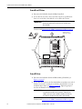
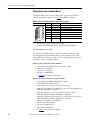
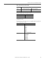
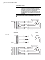
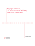
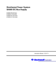
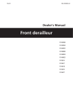
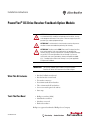
Installation Instructions
PowerFlex® DC Drive Resolver Feedback Option Module
ATTENTION: Only qualified personnel familiar with DC drives and
associated machinery should plan or implement the installation, start-up
and subsequent maintenance of the system. Failure to comply may result in
personal injury and/or equipment damage.
ATTENTION: To avoid an electric shock hazard, ensure that all power to
the drive has been removed before performing the following.
ATTENTION: This drive contains ESD (Electrostatic Discharge) sensitive
parts and assemblies. Static control precautions are required when
installing, testing, servicing or repairing this assembly. Component damage
may result if ESD control procedures are not followed. If you are not
familiar with static control procedures, reference A-B publication 80004.5.2, “Guarding Against Electrostatic Damage” or any other applicable
ESD protection handbook.
IMPORTANT
The Resolver Feedback option module can only be used with
PowerFlex DC drives with firmware version 5.002 or higher.
What This Kit Includes
•
•
•
•
•
•
•
Resolver Feedback circuit board
Resolver Interface circuit board
Two stacker connectors
Four 28 mm stand-offs and washers
Three 14 mm stand-offs and washers
Seven screws with captive lock washers
Static strap
Tools That You Need
•
•
•
•
Phillips® screwdriver (PH2)
Hexalobular screwdriver
Nut driver or wrench
Flathead screwdriver
Phillips® is a registered trademark of Phillips Screw Company.
20P-IN071B-EN-P
PowerFlex® DC Drive Resolver Feedback Option Module
What You Need to Do
To install the resolver feedback option module:
❐ Step 1:
❐ Step 2:
❐ Step 3:
❐ Step 4:
❐ Step 5:
❐ Step 6:
Step 1: Remove Power
from the Drive
Remove power from the drive
Open the drive
Install the resolver interface board
Install the resolver feedback board
Wire the resolver interface and feedback boards
Replace the protective covers and configure the resolver feedback
option module
ATTENTION: Remove power before making or breaking cable
connections. When you remove or insert a cable connector with power
applied, an electrical arc may occur. An electrical arc can cause personal
injury or property damage by:
• sending an erroneous signal to your system’s field devices, causing
unintended machine motion
• causing an explosion in a hazardous environment
Electrical arcing causes excessive wear to contacts on both the module
and its mating connector. Worn contacts may create electrical resistance.
• Remove and lock-out all incoming power to the drive.
L1
L2
L3
I
O
Step 2: Open the Drive
• To open frame A drives see Frame A Drives on page 3.
• To open frame B and C drives see Frame B and C Drives on page 4.
• To open frame D drives see Frame D Drives on page 4.
2
Rockwell Automation Publication 20P-IN071B-EN-P - June 2011
PowerFlex® DC Drive Resolver Feedback Option Module
Frame A Drives
1. Disconnect the DPI cable from the HIM (if installed).
2. Loosen the captive screws that secure the bottom front cover to the drive,
then slide the cover down and off the drive chassis.
=
Disconnect DPI cable
Loosen screws
Tightening torque:
1.5 N•m (13.3 lb•in)
3. Press in on the sides at the bottom edge of the cover and at the same time
pull the cover toward you to pull it partially off the drive chassis. Next, at
the top of the drive, pull the cover forward, away from the drive, until the
pins fit in the keyhole in the top of the cover, then carefully lift the cover
off of the drive chassis.
IMPORTANT
The HIM assembly is connected via a cable to the control
board and therefore will not pull free from the drive until
disconnected.
Continue with Disconnect the HIM Communication Cable on page 5.
When metal pin fits in keyhole, lift
cover off drive chassis.
=
Rockwell Automation Publication 20P-IN071B-EN-P - June 2011
3
PowerFlex® DC Drive Resolver Feedback Option Module
Frame B and C Drives
1. Disconnect the DPI cable from the HIM (if installed).
2. Loosen, but do not remove, the screws that secure the top and bottom
front cover to the drive, then slide the covers off the drive chassis.
IMPORTANT
The HIM assembly is connected via a cable to the control
board and therefore will not pull free from the drive until
disconnected.
Continue with Disconnect the HIM Communication Cable on page 5.
Tightening torque:
1.5 N•m (13.3 lb•in)
=
Frame B shown
Loosen
screws
Loosen
screws
Disconnect DPI
cable
Frame D Drives
1. Disconnect the DPI cable from the HIM assembly (if installed) (see
Figure 1 on page 5).
2. Loosen, but do not remove, the four hexalobular screws that secure each of
the three covers to the control pan on the drive, then slide the covers up
and off the drive chassis (see Figure 1 on page 5). Tightening torque is
noted in the illustration for reassembly.
IMPORTANT
A communication cable connects the HIM assembly to the
control board mounted on the control pan. Therefore, the
middle control pan cover and HIM assembly cannot be fully
removed from the drive until the cable is disconnected.
Continue with Disconnect the HIM Communication Cable on page 5.
4
Rockwell Automation Publication 20P-IN071B-EN-P - June 2011
PowerFlex® DC Drive Resolver Feedback Option Module
Figure 1 - Frame D Cover Removal
T15
Tightening torque:
1.5 N•m (13 lb•in)
Loosen
screws
Loosen
screws
=
Disconnect
DPI cable
Disconnect the HIM Communication Cable
• Disconnect the HIM communication cable from the connector on the
upper right corner of the Control board and remove the bottom cover.
=
All Frames
(Frame A shown)
Pull tabs out to
disconnect cable.
Rockwell Automation Publication 20P-IN071B-EN-P - June 2011
5
PowerFlex® DC Drive Resolver Feedback Option Module
Step 3: Install the
Resolver Interface Board
1. Secure the four 28 mm (1.1 in.) (longer) stand-offs and washers to the
control board. Tightening torque is 0.7 N•m (6.2 lb•in).
XR
XA
Control board
XP3
Install stand-offs
and washers
S15
Connector XRE
XRE
XFCD
Install stand-offs
and washers
S4
S21
6
Rockwell Automation Publication 20P-IN071B-EN-P - June 2011
PowerFlex® DC Drive Resolver Feedback Option Module
2. Carefully insert the stacker connector on the back of the resolver interface
board into connector XRE on the control board (identified in the previous
illustration).
IMPORTANT
Resolver
interface
board
The two pins of the stacker connector that are capped should
be to the right of connector XRE when installed on the control
board.
Control board
Resolver interface board
XRE connector
Stacker connector
Capped pins to
right
XRE connector
Control board
Bottom view
Side view
Rockwell Automation Publication 20P-IN071B-EN-P - June 2011
7
PowerFlex® DC Drive Resolver Feedback Option Module
3. Secure the resolver interface board to the stand-offs using four screws with
captive washers. Tightening torque is 0.7 N•m (6.2 lb•in).
XR
XA
Resolver interface board
XP3
P2
P3
Install screws
S15
XRE
Install screws
S1
S2
TB1
8
TB2
Rockwell Automation Publication 20P-IN071B-EN-P - June 2011
PowerFlex® DC Drive Resolver Feedback Option Module
Step 4: Install the
Resolver Feedback
Board
1. Secure the three 14 mm (0.6 in.) (shorter) stand-offs and washers to the
resolver interface board. Tightening torque is 0.7 N•m (6.2 lb•in).
XR
XA
Connectors P2 and P3
XP3
P2
P3
S15
Install stand-offs and
washers
XRE
XFCD
S1
S2
TB1
TB2
Rockwell Automation Publication 20P-IN071B-EN-P - June 2011
9
PowerFlex® DC Drive Resolver Feedback Option Module
2. Carefully insert the long pins of the stacker connectors into connectors P2
and P3 on the back of the resolver feedback option board.
IMPORTANT
The end of the stacker connectors with the long pins must
connect to the mating connectors (P2 and P3) on the resolver
feedback option board. The end of the stacker connectors with
the short pins must connect to the mating connectors (P2 and
P3) on the resolver interface board.
3. Carefully insert the stacker connectors on the back of the resolver feedback
option board into connectors P2 and P3 (identified in the previous
illustration) on the resolver interface board.
Long pins of stacker connector mate
with resolver feedback option board
Short pins of stacker connector mate
with resolver interface board connectors
P2 and P3
connectors
P2 and P3
connectors
Resolver interface board
Resolver feedback
option board
Side view
10
Rockwell Automation Publication 20P-IN071B-EN-P - June 2011
PowerFlex® DC Drive Resolver Feedback Option Module
4. Secure the resolver feedback board to the stand-offs using three screws
with captive washers. Tightening torque is 0.7 N•m (6.2 lb•in).
XR
XA
Resolver feedback board
XP3
P4
P2
P3
P2
P3
S1
S15
Install screws
XRE
S1
S2
TB1
P1
Step 5: Wire the
Resolver Interface and
Feedback Boards
TB2
Wiring the Resolver Interface Board
Table 1 - Resolver Interface Board TB1 Wire Size and Tightening Torque
Flexible (mm2)
0.140…1.500
Wire Size and Type
Multi-core (mm2)
0.140…1.500
AWG
26…16
Tightening Torque N•m (lb•in)
0.4 (3.5)
Terminal block TB1 on the resolver interface (bottom) board provides
connection points for an external 24V DC power supply input, resolver feedback
board voltage status output and resolver feedback board reset input. Table 2 on
page 12 details the connections.
The resolver feedback module can be powered via an internal or external
(customer-supplied) 24V supply. The voltage source is selected by switch S2 on
the resolver interface board. See Figure 3 on page 13 for the location of switch S2.
The customer-supplied, external 24V power supply is only needed when using
the resolver interface board with a PowerFlex DC frame A drive or Stand-Alone
Regulator under the following conditions.
• A resolver is wired to the resolver feedback board (terminal block P1)
• A digital encoder is wired to the control board
• The frame A drive has a fan(s)
Rockwell Automation Publication 20P-IN071B-EN-P - June 2011
11
PowerFlex® DC Drive Resolver Feedback Option Module
Switch S2 on the resolver interface board must be set to the “Ext” position when
using an external 24V DC power supply for the resolver feedback option module.
Table 2 - Resolver Interface Board TB1 Terminal Descriptions
1
2
3
4
5
6
Terminal
1
2
3
4
Signal
0V
+24V
OKOK+
5
6
RR+
Description
External power supply input common
External +24V DC power supply input
Resolver feedback board voltage status output common
+5…24V Resolver feedback board voltage status output
Vcc OK = voltage present and within +5…24V range
when connected to a digital input.
Vcc not OK = voltage not present or below +5V when
connected to a digital input. See Figure 2 below for
wiring example.
Resolver feedback board reset input common
+24V Resolver feedback board reset input
Figure 2 - Resolver Feedback Board Voltage Status Wiring Example
In this example digital input 2, on drive I/O TB2, is configured as an Enable input. When the signal
from terminals 3 and 4 on TB1 of the Resolver Interface board = “VCC not OK,” the drive is disabled.
Resolver Interface
Board TB1
Drive Control Board
I/O TB2
1
11
2
12
3
13
4
14
5
15
6
16
Digital Input 2
Digital Input Common
17
18
24V Supply Common
19
+24V DC Supply
20
Terminal block TB2 on the resolver interface board is used to send the signals
from the primary digital encoder installed and wired to the encoder terminal
block on the control board to a second “follower” drive/regulator. When the
outputs on TB2 are used, switch S1 on the resolver interface board must be set to
match the encoder power supply voltage set for the primary encoder on the
follower drive’s control board (set via switch S21). See the PowerFlex Digital DC
Drive User Manual, publication 20P-UM001, for details on installing a primary
digital encoder and using switch S21 on the control board.
The S1 switch settings correspond to each of the three LEDs on the left side of
the resolver interface board and indicate the selected supply voltage as follows:
• Green LED indicates a 5V supply when lit (on)
• Yellow LED indicates a 12V supply when lit (on)
• Blue LED indicates a 24V supply when lit (on)
See Figure 3 on page 13 for the location of switch S1 and corresponding LEDs on
the resolver interface board.
See “Cable and Wiring Recommendations” in the PowerFlex Digital DC Drive
User Manual, publication 20P-UM001, for encoder wiring recommendations.
12
Rockwell Automation Publication 20P-IN071B-EN-P - June 2011
PowerFlex® DC Drive Resolver Feedback Option Module
Table 3 - Resolver Interface Board TB2 Terminal Descriptions
1
2
Terminal
1
2
3
4
5
6
7
3
4
5
6
7
Signal
A+
AB+
BZ+
ZShield
Description
Encoder A
Encoder A (NOT)
Encoder B
Encoder B (NOT)
Encoder Z
Encoder Z (NOT)
Connection point for encoder cable shield
Table 4 - TB2 Encoder Output Specifications
Max. Output Current
Max. Output Low Voltage
Min. Output High Voltage
20 mA
0.5V @ 20 mA
Vcc - 2.6V @ 20 mA (where Vcc = 5V or 30V)
Figure 3 - Resolver Interface Board Switch and LED Locations
P2
P3
Switch S1 shown in
the +24V selection
position
XRE
Encoder output voltage LEDs
(set with S1)
+5V position
+12V position
Green LED - 5V
+24V position
Yellow LED - 12V
Blue LED - 24V
Internal (Int) supply position
External (Ext) supply position
Switch S2 shown in
the “Ext” position
S1
S2
TB1
TB2
Rockwell Automation Publication 20P-IN071B-EN-P - June 2011
13
PowerFlex® DC Drive Resolver Feedback Option Module
Wiring the Resolver Feedback Board
Terminal block P1 on the resolver feedback option (top) board provides the
connection points for a single resolver. Table 5 details the connections.
1 2 3 4 5
6
7 8
Table 5 - Resolver Feedback Board P1 Terminal Descriptions
Terminal
8
7
6
5
4
3
2
1
Signal
REF HIGH
SHIELD
REF LOW
SIN HIGH
SHIELD
SIN LOW
COS HIGH
COS LOW
Description
Positive Reference signal
Connection point for resolver cable shield
Negative Reference signal
Positive Sine signal
Connection point for resolver cable shield
Negative Sine signal
Positive Cosine signal
Negative Cosine signal
• P1 terminal block part number: 1639300000
• P1 terminal block material number: BL 3.50/08/90F SN BK BX
Recommended Resolver Cable
For the best results, Belden® 9730 (or equivalent) cable is recommended. For
retro-fit applications where Reliance Electric™ resolvers (800123-xxx), wiring
(417900-207CG) or Automax™ systems were used, existing wiring may be used
(assuming it is in good working condition).
Belden 9730 (or Equivalent) Cable Attributes
• 3 twisted pairs, 24 AWG, shielded, -20 to +80 °C, 300V
• Inductance = 0.23 μH/ft
• Capacitance = 12.5 pF/ft
• Resistance = 24 Ω/1000 ft
• See Table 6 for maximum cable lengths
Reliance Electric 417900-207CG Cable Attributes
• 3 Twisted Pairs, 18 AWG, unshielded, 80°C, 300V
• Chrome FPR Jacket, Plenum Rated
• Twists Per Inch: 2-3 twists per inch of wire lay per pair
• Inductance per 1000 Feet: 0.13 μH ±10% as read on a GEN_RAD Model
1658 RLC Digibridge or equivalent
• Capacitance Per Pair: not to exceed 30 pF/ft ±0.3 pF as read on a
GEN_RAD Model 1658 RLC Digibridge or equivalent
• Capacitance Difference Pair to Pair: not to exceed 0.6 pF/foot as read on a
GEN_RAD Model 1658 RLC Digibridge or equivalent
• Resistance per 1000 Feet: 17.15Ω ±10%
• Insulation Thickness: 0.008 in.
• Conductor Stranding 16/30
• Jacket Thickness: 0.018 in.
• See Table 6 for maximum cable lengths
14
Rockwell Automation Publication 20P-IN071B-EN-P - June 2011
PowerFlex® DC Drive Resolver Feedback Option Module
Table 6 - Maximum Resolver Cable Length
Maximum Cable Length
Cable
x1 and x2 Resolver Speed Ratio
x5 Resolver Speed Ratio
Belden 9730
305 m (1000 ft)
183 m (600 ft)
417900-207CG
240 m (800 ft)
150 m (500 ft)
Resolver Feedback Option Board Specifications
Consideration
Excitation Frequency
Excitation Voltage
Resolver Feedback Voltage
Description
2381…9300 Hz
8…26 Vrms
2 Vrms +/- 300 mV
Compatible Resolvers
The table below specifies which resolvers are compatible with the PowerFlex DC
resolver feedback option module.
Manufacturer
Advanced Micro Controls Inc.
Reliance Electric
Tamagawa
Manufacturer Model/Catalog Number
R11X-C10/7
800123-R
800123-1R
800123-2R
800123-S
800123-1S
800123-2S
800123-T
800123-1T
800123-2T (flange mounted)
TS-2014N181E32
TS-2014N182E32
TS-2014N185E32
TS-2087N1E9
TS-2087N2E9
TS-2087N5E9
TS-2087N11E9
TS-2087N12E9
Rockwell Automation Publication 20P-IN071B-EN-P - June 2011
15
PowerFlex® DC Drive Resolver Feedback Option Module
Resolver Wiring Diagrams
IMPORTANT
The shield connections must only be made at the drive end of the
cable (resolver end of cable shield is unattached) as shown in the
diagrams below. Grounding both ends of the shielded cable can result
in ground loops that could damage the resolver and/or drive.
Also, the resolver connections are considered signal level wiring and
MUST be run separate from control and power wiring (and at least 12
inches apart).
Figure 4 - Resolver Interface Connection Example for Clockwise Rotation - Count
Up
Terminal Block P1
Resolver
+
REF HIGH 8
-
SHIELD 7
-
+
+
REF
-
-
+
SIN
COS
REF LOW 6
SIN HIGH 5
SHIELD 4
+
+
-
-
+
+
-
-
-
+
SIN LOW 3
COS HIGH 2
COS LOW 1
Figure 5 - Resolver Interface Connection Examples for Clockwise Rotation - Count
Down
Terminal Block P1
Resolver
Reverse Polarity of Sine
or Cosine Signals
REF HIGH 8
SHIELD 7
+
+
-
-
-
+
REF
-
+
SIN
COS
REF LOW 6
SIN HIGH 5
SHIELD 4
-
+
+
-
-
+
SIN LOW 3
COS HIGH 2
COS LOW 1
REF HIGH 8
SHIELD 7
+
+
-
-
+
+
-
-
+
REF
+
SIN
COS
REF LOW 6
SIN HIGH 5
SHIELD 4
+
+
-
-
-
SIN LOW 3
COS HIGH 2
COS LOW 1
16
-
+
+
-
Rockwell Automation Publication 20P-IN071B-EN-P - June 2011
+
PowerFlex® DC Drive Resolver Feedback Option Module
Step 6: Replace the
Protective Covers and
Configure the Resolver
Feedback Option Module
1. Close the drive covers in the reverse order as described in Step 2: Open the
Drive on page 2.
2. Configure the resolver feedback option module. See the PowerFlex Digital
DC Drive User Manual, publication 20P-UM001.
Rockwell Automation Publication 20P-IN071B-EN-P - June 2011
17
1S7A72
U.S. Allen-Bradley Drives Technical Support - Tel: (1) 262.512.8176, Fax: (1) 262.512.2222, E-mail: [email protected], Online: www.ab.com/support/abdrives
www.rockwellautomation.com
Power, Control and Information Solutions Headquarters
Americas: Rockwell Automation, 1201 South Second Street, Milwaukee, WI 53204-2496 USA, Tel: (1) 414.382.2000, Fax: (1) 414.382.4444
Europe/Middle East/Africa: Rockwell Automation, Pegasus Park, De Kleetlaan 12a, 1831 Diegem, Belgium, Tel: (32) 2 663 0600, Fax: (32) 2 663 0640
Asia Pacific: Rockwell Automation, Level 14, Core F, Cyberport 3, 100 Cyberport Road, Hong Kong, Tel: (852) 2887 4788, Fax: (852) 2508 1846
Publication 20P-IN071B-EN-P – June 2011
Copyright © 2011 Rockwell Automation, Inc. All rights reserved. Printed in USA.