1
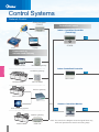
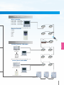
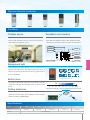
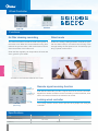
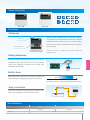
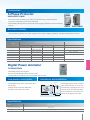
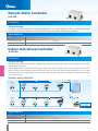
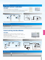
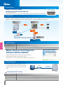
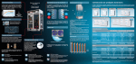
COMMERCIAL AIR CONDITIONERS R410A All DC Inverter VRF V5 X Series 50/60Hz Con trol Systems Control Systems Network Control Data converter CCM15 Centralized Control Indoor Centralized Controller (Touch key) X,Y,E CCM30 iPad Laptop Connectable to various sized Gateway IMM Software M-interface gateway Control system Indoor Centralized Controller LonWorks gateway X,Y,E MD-CCM03 LonWorks BMS MD-LonGW64 BACnet gateway BACnet BMS MD-CCM08 Outdoor Centralized Monitor Web monitoring system F1,F2,E K1,K2,E Modbus gateway MD-CCM02 Modbus BMS 55 CCM-18A Note: The wires in the diagram show the signal flows only, while not represent the actual connecting ways. Individual control Wired controller KJR-10B KJR-86C KJR-12B KJR-120B KJR-90A KJR-90C KJR-29B KJR-120C Remote controller RM02 RM05 R05 R51 R71 Accessories Control system Card-key Interface MD-NIM05 MD-NIM05 Wired controller Card-key Infrared Sensor MD-NIM09 Infrared control box Wired controller Infrared sensor module Outdoor units 56 Comparison of Controllers Item Model name Remote controller RM05/ RM02 R05 / MAX. controllable IDU A/C control R51/ R71 Wired Controller KJR-10B /KJR-12B 1 KJR-120B 1 Centralized Controller KJR-90A /KJR-86C KJR-29B KJR-90C CCM30/ MD-CCM03 MD-CCM09 KJR90B 1 1 64 64 16 On/Off Ⴠ Ⴠ Ⴠ Ⴠ Ⴠ Ⴠ Ⴠ Ⴠ Ⴠ Ⴠ Operation mode setting Ⴠ Ⴠ Ⴠ Ⴠ Ⴠ Ⴠ Ⴠ Ⴠ Ⴠ Ⴠ Fan speed setting Ⴠ Ⴠ Ⴠ Ⴠ Ⴠ Ⴠ Ⴠ Ⴠ Ⴠ - Room temp. setting Ⴠ Ⴠ Ⴠ Ⴠ Ⴠ Ⴠ Ⴠ Ⴠ Ⴠ - Vertical swing Ⴠ Ⴠ/- Ⴠ - - - - - - - Horizontal swing Ⴠ Ⴠ Ⴠ Ⴠ Ⴠ Ⴠ/- Ⴠ Ⴠ Ⴠ - Air direction Ⴠ/- -/Ⴠ Ⴠ - - - - - - - Economic mode Ⴠ Ⴠ Ⴠ Ⴠ Ⴠ - - - - - Central setting - - - - - - - Ⴠ Ⴠ Ⴠ Keyboard lock Ⴠ Ⴠ/- Ⴠ Ⴠ Ⴠ - Ⴠ Ⴠ Ⴠ - Mode lock - - - - - - - Ⴠ Ⴠ - Remote signal receiving - - - - - - Ⴠ - - - -/Ⴠ - - - - -/Ⴠ - - - - Silent mode - - - - Ⴠ - Ⴠ - - - Backlight Ⴠ Ⴠ/- Ⴠ Ɣ Ⴠ -/Ⴠ Ⴠ Ⴠ Ⴠ Ⴠ Current time Ⴠ/- - Ⴠ Ⴠ/- Ⴠ Ⴠ/- - - Ⴠ - RC prohibition - - - - - - - Ⴠ Ⴠ - Address - - - - - - - Ⴠ Ⴠ - Error code - - - - Ⴠ - - Ⴠ Ⴠ - Room temp. - - - - - -/Ⴠ - Ⴠ Ⴠ - Period - - - - - - - - Week - On/Off per day - - - - - - - - 4 - On/Off per week - - - - - - - - 28 - On/Off timer Ⴠ Ⴠ Ⴠ Ⴠ Ⴠ Ⴠ/- Ⴠ Ⴠ Ⴠ - FOLLOW ME -/Ⴠ - - -/Ⴠ - - Ⴠ - - - Emergent stop - - - - - - - Ⴠ - - Emergent start - - - - - - - Ⴠ - - Address setting Ⴠ - - Ɣ - - Ⴠ - - - BMS access - - - - - - - Ⴠ - - Control via internet - - - - - - - Ⴠ - - Air filter cleaning reminding - - - Ⴠ/- Ⴠ - Ⴠ Ⴠ/- - - function 26ഒ shortcut setting Control system Display Timer Control : Available controller functions : Not available controller functions 57 Wireless Remote Controller RM02 RM05 R05 R51 R71 Functions Portable device Simplified user interface The wireless remote controller is a portable control Users can synchronize the air conditioners’ param- device that enables users to control the A/C any- eters with the display panel on the wireless remote where within a distance of 11m. controller to precisely control a room's environment. Temp. 1 Transmitting display 2 Running mode 4 ON Economic operation 3 ON/OFF 5 Time 6 Lock OFF 8 Time ON/OFF 9 Fan speed Control system 7 Background light The background light allows users to operate the device in a dark room. The device lights up when a AUTO button is pressed, and turns off when a given opera- Auto mode Dry mode Timer Lock Heat mode Cool mode Fan mode tion is completed. Built-in timer Eco mode Address setting Follow Me *The follow me function is available for RM02 The built-in daily timer offers the convenience of auto0 times. 24°C ON matically starting and stopping the system at set 3 6 9 12 15 OFF 18 21 Time The indoor unit is set to work in automode from 8:00 to 20:00 Setting addresses Besides the machine's auto addressing function, users can set the indoor unit's address on the wireless remote controller RM05/RM02. Specifications Specifications Model Dimensions (H×W×D)(mm) Power (V) RM02 RM05 R05 R51 R71 150×60×15 150×65×20 150×65×20 140×60×15 125×42×27 1.5V(LR03/AAA)×2 58 Wired Controller AUTO Auto mode Dry mode Heat mode Cool mode Fan mode Timer Lock Filter cleaning remind Follow Me Address setting Silent mode KJR-90C KJR-29B Functions Air filter cleaning reminding Silent mode The wired controller records the total running time of Under the cooling, heating and auto mode,when oper- the indoor unit. When the accumulated running time ate the silent mode, it can reduce the running noise reaches the pre-set value, it will remind users need to through setting the fan speed to low. This will help you clean the air filter of the indoor unit. bring a quieter environment. Clean the filter regularly can keep indoor air fresh and clean, good for your health. Control system *Available for KJR-10B/KJR-29B/KJR-90C model. Remote signal receiver Remote signal receiving function KJR-29B and KJR-90C provide a signal receiver for remote controller. Air filter cleaning reminding icon Signal from remote controller can be received by a wired controller, then sent to the indoor unit and it conveniences to control. Locking wired controller Silent Key KJR-29B (Touch key) The locking function can be used to prevent other people from using the controller. Specifications Model Dimensions (H×W×D)(mm) Power (V) 59 29B 90C 120×120×20 86×86×16.5 DC 5V Wired Controller AUTO KJR-10B Auto mode Dry mode Heat mode Cool mode Fan mode Timer Lock Filter cleaning remind Follow Me Address setting KJR-12B Functions Follow me With the FOLLOW ME function, the wired controller Sensor part can detect the air temperature at the user’s altitude instead that of the ceiling or floor. This helps making the room environment comfortable and the temperature accurate. FOLLOW ME Button *Follow me function is available for KJR-12B, KJR-29B and KJR-90C model. Setting addresses With the address setting function,and easy for the Control system installation and future service. The service person can set the address for indoor unit by KJR-10B, KJR-29B and KJR-90C. Wired controller Built-in timer Built-in daily timer offers the convenience of automatically starting and stopping the system at set times. 24°C ON 0 3 6 9 12 15 OFF 18 21 Time The indoor unit is set to work in automode from 8:00 to 20:00 Easy connection Display panel Wired controller The wired controller conveniently connects to the indoor unit's display panel via connecting wire. Indoor main board Specifications Model Dimensions (H×W×D)(mm) Power (V) 10B 12B 120×120×15 120×120×15 DC 5V 60 Wired Controller KJR-90A KJR-86C KJR-120B Functions Features 6PDOODQGHDV\WRLQVWDOO 6XLWDEOHIRUDOOW\SHVRILQGRRUXQLWV &DQEHVWRUHGLQDPRXQWLQJFDELQHW Built-in timer KJR-90A Built-in daily timer offers the convenience of automatically starting and stopping the system at set times. Control system Mode setting Mode-button hidden controller:Press the temperature buttons ŸDQGźVLPXOWDQHRXVO\IRUVHFRQGVWRVHOHFWWKHRSHUD26°C Shortcut setting tion mode: COOL and HEAT. The design is suitable for hotels, Combination key hospitals, schools and other similar types of buildings. Selecting mode KJR-86C Auto mode For V4 plus R series used only. Under the auto mode of V4 plus R system, it can automatically switch to COOL or HEAT mode according to the temperature difference value between Tf(indoor temperature) and Ts(setting temperature) KJR-120B Specifications Model Dimensions (H×W×D)(mm) Power (V) 61 90A 90×86×13 86C 86×86×18 DC 5V 120B 120×120×20 Wired Controller HRV Wired Controller KJR-27B Functions HRV controller Built-in timer KJR-27B is individually designed for HRV—Heat Recovery Ventilator. The HRV can work in the following modes: exhaust, air supply, bypass, heat exchange, and auto. Built-in daily timer offers the convenience of automatically starting and stopping the HRV at the set times. AUTO->HEAT EXCHANGE-> EXHAUST->BYPASS->AIR SUPPLY Setup screen example Set to wednesday: 8:00 to 20:00 24°C ON 0 3 6 9 12 15 OFF 18 21 Time Specifications Model KJR-27B Dimensions(H×W×D)(mm) 120×120×15 Power (V) 198-242V(50/60Hz) Weekly Schedule Controller Control system MD-CCM04 KJR-120C Functions Simple disign Weekly schedule wired controller has different appearances to choose. They can query the indoor temperature and the setting parameters of the weekly schedule. They can show the error codes and running state of the indoor unit. With the LCD backlight, and enables users to operation the device in a dark room. Delay function The function is specially designed for a person who is working overtime. During the weekly schedule running, press Delay button, then it will delay 1 hour or 2 hours to turn off the air conditioner. Weekly schedule With the weekly schedule function, and users can set up 4 periods schedule per day to avoid setting frequently.During operation, can change the mode, fan speed, temperature, and then the next startup will run at the status according to the latest setting. Specifications Model MD-CCM04 KJR-120C Dimensions (H*W*D)(mm) 120×120×15 120×120×20 DC 5V DC 12V Power (V) 62 Centralized Controller Indoor Centralized Controller MD-CCM03 Cool mode Swing Filter cleaning remind Heat mode Keyboard lock Remote controller lock Timer Fan mode Net CCM30 Cooling lock Heating lock Net connection Functions Centralized control Three lock modes The centralized controller is a multifunctional device that can control up to 64 indoor units within a maximum connection length of 1,200m. The device connects to the master outdoor units of Midea's newly designed products to simplify and centralize the wiring configuration. The 2 ways of connecting are as follow: Centralized controller provides a superior way to manage the indoor units. Users are able to make their own choice from locking the wireless controller, locking the running mode or lock the centralized controller's keyboard as they wish. X,Y,E P,Q,E Control system X,Y,E P,Q,E X,Y,E P,Q,E X,Y,E Locking Running Mode X,Y,E Locking Remote Controller Locking Keyboard *If it connects to XYE ports of master ODU, ODU must be set to auto addressing mode. Indoor unit working status display Air filter cleaning reminding function The centralized controller displays indoor units' working status and error codes so users can easily identify faults via checking the error codes table in the user's manual before contacting a service engineer. The air filter cleaning reminder function is only available on the touch-key central controller CCM30. The "FL" icon indicates that the air filter in a given indoor unit needs cleaning. Error code or protection code Connecting status matrix # ERROR INLINE ON OFF PROTECT MODE 01 02 03 04 05 06 07 08 09 10 11 12 13 14 15 16 AUTO 00+ (1.6) GROUP QUERY RUN SET #GROUPALL Air filter cleaning reminding icon 16+ SET.TEMP ROOM.TEMP T3 Hr ON 63 OFF T2A T2B 32+ FAN Hr 48+ OPR.UNSUCCESS CCM30 Functions Stylish design Single/unified control CCM's stylish design suits high-end environments. The control object can be either a single unit or all The keyboard lock function is used to prevent units, which vastly simplifies the control process. operational mistakes. Operation signal feedback ensures that all units are working in the correct mode. OPR.UNSUCCESS Easy installation Centralized controller offers two different appearances to mostly suit the installation. The A structure must be embedded into the wall and the B structure doesn't need. Both of them are easy to operate. Control system Upper side outlet A Rear side outlet B Under side outlet B structure leading-out mode sketch Access to network monitoring The centralized controller is able to bridge up to 64 indoor units on the network monitoring and building management systems. X,Y,E F1,F2,E MAX.64 Indoor CCM Specifications Model Model Dimensions (H*W*D)(mm) Power (V) MD-CCM03 CCM30 179×119×74 180×122×78 and 180×122×68 198-242V(50/60Hz) 64 Centralized Controller Weekly Schedule Centralized Controller AUTO Auto mode Cool mode Heat mode Fan mode Dry mode Swing Keyboard lock Cooling lock Heating lock Remote controller lock Weekly schedule MD-CCM09 Functions Weekly schedule 8:00 MD-CCM09 can include up to 64 indoor units in the 16:00 23:59 Sun 28°C 22°C Mon 26°C 22°C 17°C 23°C Tue 26°C 22°C 17°C 23°C day, and select the desired running mode and room Wed 26°C 22°C 17°C 23°C temperature. The operating object can be a single Thu 26°C 22°C 26°C Fri 26°C 22°C 26°C Sat 28°C off 24°C weekly schedule. Users can set up to 4 periods per indoor unit or all the indoor units. 24°C Control system Three lock modes Single/unified control mode Centralized controller MD-CCM09 provides a The control object can be either a single unit or all superior way to manage the indoor units. Users are units, which vastly simplifies the control process. able to make their own choice from locking the Operation signal feedback ensures that all units are wireless controller, locking the running mode or lock working in the correct mode. the MD-CCM09's keyboard as they wish. OPR.UNSUCCESS Locking Running Mode Locking Remote Controller Locking Keyboard Indoor unit working status display MD-CCM09 displays indoor units' working status and error codes so users can easily identify faults via Error code or protection code checking the error codes table in the user's manual before contacting a service engineer. *If it connects to XYE ports of master ODU, ODU must be set to auto addressing mode. Specifications Model MD-CCM09 Dimensions (H*W*D)(mm) 179×119×74 Power (V) 65 198-242V(50/60Hz) Connecting status matrix Centralized Controller Unified On/Off Controller KJR-90B Unified controller design with graceful appearance and explicit panel. Can control single or group indoor units. Functions Unified control KJR-90B offers on/off and heating/cooling functionality for indoor units based on preset temperatures to ensure easy management. 28°C 20°C cooling heating Centralized control KJR-90B can be used to centrally control up to 16 indoor units. Max.16 Control system Light indicator The LEDs on KJR-90B indicate the indoor units' running status for easy fault detection. The lights switch off automatically to save energy once a given operation is complete. The indicators are as follows: Light Single On/Off key Blue Red Flash Cooling/Fan Heating IDU Error EEPROM Error Unified On/Off key Easy installation KJR-90B can be easily mounted on the built-in cabinet: Specifications Model KJR-90B Dimensions (H*W*D)(mm) 90×86×8 Power (V) DC 5V 66 Centralized Monitor Outdoor Centralized Monitor MD-CCM02 Query parameters 4-way/EXV valve Protection/ Error codes Power consumption Forced Cooling With the ODU communication With the PC communication Forced Cooling Functions ODU parameters display MD-CCM02 enables users to easily check outdoor units' running status, including frequency, temperature, current, pressure, protection codes and error codes. Forced Cooling Graph 2 LCD Screen Control system Access to network monitoring MD-CCM02 can connect up to 8 refrigerant systems and 32 outdoor units to the network system. K1,K2,E Max.4 system 1 Max.32 K1,K2,E Max.4 system 2 K1,K2,E Max.4 system 8 Specifications Model MD-CCM02 Dimensions(H×W×D)(mm) 120×120×15 Power (V) 67 198-242V(50/60Hz) Central Control Software Control system IMM Software PC SMS modem Web Access Laptop Router Pad IMM Gateway M-interface web gateway A/C Systems Power ammeter Outdoor units Indoor units 68 Central Control Software IMM(Intelligent Manager of Midea) 4th Generation Network Control System Functions Intelligent Manager of Midea, designed specifically to control VRF systems, is based on a centralized format and dedicated to the complete control and monitoring of all the system’s functions. It can be used as a flexible multi-purpose system and applied to a variety of needs, according to the scale, purpose and control method of each building. Up to 4 M-interfaces, 64 refrigerant systems, 1,024 indoor units, and 256 outdoor units can be controlled by one PC. Web Access Electricity charge distribution Schedule management Low-load operation indicate Central building monitoring and control Generate operational history reports (daily, weekly, monthly) Fault display & Warning message Energy saving management Air filter cleaning reminding function SMS modem (optional) Emergency stop and Alarm signal output User friendly operation Control system Network Control Application Xfc!Bddftt Mpdbm Can run on Window 7_32/64 bit, Window XP_32 bit and Window 8. Can monitor and control A/C anytime, anywhere by PC, iPhone, iPad and notebook computer. Support WEB access: IE, Firefox, Safari and Chrome. Enables remote access through DSL, VPNs and so on. Max.IDU:1024 69 Various Managements Simple Operation and Management Click & Operate, a user-friendly interface allows even non-experts to perform the building management system easily. Data Management Operational information of individual indoor units are monitored, allowing for distribution of power consumption at outdoor units. Stores operation data on multiple systems and displays it in graphical format for visual management. Uses IMM software to generate tenant reports and help building owners bill for energy use. Electricity Charge Distribution(Patented) Provides information on proportional electrical power distribution to optimize electricity consumption management. Uses software to calculate electric power proportional distribution, output and save electricity consumption data for each indoor unit (or group) which is connected to the intelligent manager. Applies the patented Midea Calculation Method to calculate consumption rates according to capacity demand which is based on various parameters: setting temperature, room temperature, running mode, rated HP, public areas, unused rooms, and nighttime use; outputs this information on a charge calculation sheet to evenly divide power consumption charges among tenants. Hightlights Visual Navigation With the web access function, a PC, laptop computer or a smart phone can be used as a remote controller. Clicking the jump button will display a list of all available screens. Clicking the back button will return to the previous screen. Energy Saving Management Data Backup Based on a predetermined schedule, the Intelligent Manager executes capacity control and intermittent operations on all air conditioning units to maintain a The M-interface will automatically back up data on the installed SD card (2GB) in case system failure occurs, such as: power failure or system dam. IMM software also stores the previous 3 months' operational data on high comfort index. Control system Web Access function the HDD. Schedule Control Multiple Languages Automatically performs facility start/stop control, switches the operating mode, sets temperatures and enables/disables the remote control according to the Provides seven language settings: English French Italian Russian German Spanish present time schedule. 4 sections and 20 actions per day for each single unit or group. Simple Chinese Warning Message Electricity Charge Distribution The system can receive error messages from air conditioning units in more than one buildings or structures via public phone lines. Electricity charges can be easily divided when billing users for air conditioning power charges; for example, for tenants in a commercial building, offices in a *Requires the Midea "SMS Modem" to send automatic warning messages to designated phone numbers. rented building, or rooms in a hotel. 70 Weekly schedule control ● With weekly schedule function for iPad and Web function. ● Multiple sections in each day for single unit or group. ● Automatically performs facility start/stop control, operating mode, setting temperatures and according to the present time schedule. Web features ● Query and control single unit or group. ● Weekly schedule setting: can set multiple sections in each day for single unit or group. ● Group user control : a user can use the same ID to manage hundreds of CCM15, when selecting the "As group user" button on the login page. Control system ● History error: easy service and management with history error function. Intelligent control ● The air conditioner remote control can be realized by mobile phone or tablet computer. ● You can query and control the running state of the air conditioner any time and any where and even make an appointment in advance. ● Can remotely turn off the air conditioner to avoid the power waste, when you are in a hurry to leave. 72 Accessories BACnet® BMS Gateway MD-CCM08 Contains 4 groups of RS485 communication ports and be able to connect up to 256 indoor units or 128 outdoor units to the BMS. Be free to connect to the BMS or not. Built-in WEB function. Network example Each port can connect to XYE ports of IDU/ODU or the K1K2E ports of the outdoor units. Each port can also connect to one CCM03 or one CCM02 through F1F2E ports. XYE MD-CCM08 CCM30 Indoor units F1 F2 E XYE HUB Outdoor units Indoor units BACnet/IP protocol TCP/IP F1 F2 E PQE XYE Control system CCM02 Web monitoring system BMS Outdoor units K1 K2 E Indoor units PQE *If it connects to XYE ports of master ODU, ODU must be set to auto addressing mode. Monitoring units online MD-CCM08 allows users to track units' operational status and change their running parameters on Internet Explorer for maximum control convenience. Wide compatibility CCM08 has a wonderful adaptability to the BMS 1 Company BMS software SIMENS APOGEE Brand APOGEE A N Y W H E R E TM 2 TRANE Tracer Summit TRACER SUMMT 73 3 Honeywell Alerton 4 Schneider Andover 5 Johnson METASYS Accessories Modbus BMS Gateway CCM-18A Supports Modbus protocol networks Bridges the Midea central A/C system to BMS Connect up to 64 or 16 indoor units and 4 outdoor units Built-in WEB server function *4 outdoor units must be in the same system Network example 1)TCP connection method CCM-18A Modbus TCP/IP Outdoor units K1K2E/ XYE bus Max.4 K1 K2 E PQE Modbus system Indoor units Max.64 Control system 2) RTU connection method CCM-18A Modbus system Modbus RTU Outdoor units K1K2E/ XYE bus Max.4 K1 K2 E PQE Indoor units Max.64 *1. If it connects to XYE ports of master ODU, ODU must be set to auto addressing mode. 2. XYE and K1K2E must be connected hand by hand. Config A/C System via Web When the Modbus network is set, users can conveniently configure their A/C network system over the Internet using different TCP/IP browsers. 74 Accessories LonWorks® BMS Gateway MD-LonGW64 Compliance with LonMark protocol,and realizes the management and control of A/C. Can connect up to 64 indoor units to the BMS. Realizes non-polarity communication,and also the application can be download online. Network example Connection method 1: Suitable for all of air conditioner systems and connect max.64 indoor units. MD-LonGW64/E RS485 X,Y,E X,Y,E X,Y,E X,Y,E BMS system Control system Connection method 2: Only suitable for V4 plus system and connect max.64 indoor units. System 1 MD-LonGW64/E P,Q,E RS485 X,Y,E X,Y,E X,Y,E P,Q,E System 2 P,Q,E System N BMS system *If it connects to XYE ports of master ODU, ODU must be set to auto addressing mode. Specifications Model Dimensions (H*W*D)(mm) Power (V) 75 MD-LonGW64 319×251×61 177~265V AC(50Hz/60Hz) X,Y,E X,Y,E Accessories 3-Phase Protector HWUA/DPB71CM48 Detect the power condition and make the corresponding protecting action. Protect the compressor from being damaged. Automatically distinguish the abnormal power supply conditions and automatically recover. HWUA DPB71CM48 Excellent reliability The protector protects the entire system from power supply problems, and auto restart after recovery. Specifications With over/under voltage function Without over/under voltage function Model HWUA Power supply (V-N-Hz) DPA53CM23 HWUA DPB71CM48 220~480V-3N 50/60Hz 208~480V-3N 50/60Hz 220~480V-3N 50/60Hz 380~480V-3N 50/60Hz 2.9 VA 50Hz: -20 C ~60 C 60Hz:-20 C ~50 C 7 VA Over voltage 12% 12% 18% 18% Under voltage -12% -12% -12% -12% 8% / 8% 8% 90×69×35 81×67.2×17.5 90×69×35 81×67×35 Temp. range( C) Rated operational power(VA) Phase imbalance Dimensions(W×H×D)(mm) -20 C~50 C -20 C ~50 C 208~480V-3N 50/60Hz 50Hz: -20 C~60 C 60Hz:-20 C~50 C 13 VA -20 C~50 C 2.9 VA DPA51CM44 13 VA / 81×67.2×17.5 Control system Digital Power Ammeter DTS634/DTS636 Calculates power consumption. Does not need adjusting after long-term use. Corresponds one outdoor unit to one digital power meter. 15mm long crack 72 LCD Impulse A phase B phase C phase 201 The digital power meter consumes minimal energy. Voltage circuit: less than 2W/10VA Current circuit: less than 2.5VA Indications and installation 230 Low power consumption 131 145 The digital power meter is tested after manufacture so it can be immediately deployment and used on-site. The LED indicators and installation schematic are shown in the figure on the left. Specifications Model Dimensions (H*W*D)(mm) Power (V) DTS634/DTS636 230×145×72 200V-500V(50/60Hz) 76 Remote Alarm Controller KJR-32B Functions Simple design KJR-32B is specially designed for engineering applications. It does not display the ODU’s working parameters, but it can connect to the alarm device when ODU is working abnormally, the RUN light will flash. Specifications Model KJR-32B Dimensions (H*W*D)(mm) 150×85×70 198-242V(50/60Hz) Power (V) Indoor Unit Group Controller KJR-150A Functions Simple design Control system KJR-150A is a indoor group controller, designed specifically for V4 plus indoor units. It can connect up to 16 indoor units through XYE ports. With a display panel connected to KJR-150A, signal from wired controller and remote controller can control a group of indoor units simultaneously and all indoor units will run at the same setting parameters. You can also control the indoor units separately in each room by remote controller. The indoor unit will run at the state according to the latest setting. System wiring diagram PQE KJR-150A 1# X Y E V4+ Outdoor Unit V4+ indoor unit(1#) X Y E V4+ indoor unit (2#) X Y E V4+ indoor unit (3#) X Y E V4+ indoor unit N# (N) X Y E PQE KJR-150A 16# V4+ indoor unit(1#) V4+ indoor unit (2#) V4+ indoor unit (3#) V4+ indoor unit N# (N) XYE POWER X X Y E X Y E X Y E X Y E X Y Y E E NOTE : The Maximum Number of Indoor units is 64. Centr alized contr oller * If you need to use a centralized controller, you can connect to the XYE from an outdoor unit. Specifications Model Dimensions (H*W*D)(mm) Power (V) 77 KJR-150A 150×85×70 198-242V(50/60Hz) Accessories Infrared sensor controller MD-NIM09 Automatically adjust the room environment. Automatically extend the shutting down time, avoiding frequent ON/OFF. Graceful appearance accommodates itself to different buildings. Installation example Electrical wiring Infrared sensor controller Wired controller Infrared inductive control box Wired controller Display panel CN3 CN2 CN1 MD-NIM09/E S1 MD-NIM09 MD-NIM09 Infrared sensor Network module port Display panel port Wired controller Indoor main board Remote controller Remote controller or wired controller can control indoor unit. Specifications Model MD-NIM09 Dimensions(H×W×D)(mm) Senor part: 46×30×25.6, Control box: 86×72.8×15.5 Power DC 5V Control system Hotel Card Key Interface Module MD-NIM05 Cooperate with the wired controller to automate control. Eliminates the need for high voltage power, making the device safe and steady. Includes a build-in auto-restart function. Remote controller or wired controller can control indoor unit. Installation example Electrical wiring Display panel port Hotel card key interface module Indoor main board Wired controller Network module port Wired controller Display panel Check MD-NIM05 MD-NIM05 Hotel Card-inserter MD-NIM05 CN1 Card key 5 meters RUN Wired controller CN2 COM1 GND To hotel control system Remote controller Specifications Model Dimensions (H*W*D)(mm) Power (V) MD-NIM05 86×72.8×15.5 DC 5V 78 Accessories AHU Control Box AHUKZ-01A/AHUKZ-02A/AHUKZ-03A V4+ functions inside. Can be used to connect VRF outdoor units with DX AHU or other brand indoor units Introduction AHUKZ-01A/AHUKZ-02A/AHUKZ-03A is an independent control box that can connect a AHU to V4 plus system to realize centralized control with V4 plus system. Control box wiring is as follows: Power supply Power supply Centralized Controller P/Q/E X/Y/E Wired Controller T1/T2/T2B/T2C G/L pipe Fan/pump x EXV Power supply DX AHU or other brand indoor units Specifications Control system Model Dimensions(H×W×D)(mm) Power (V) AHUKZ-01A/AHUKZ-02A/AHUKZ-03A 335×375×150 220-240V~ 50Hz 208-230V~ 60Hz Midea Outdoor Unit Diagnosis Software MCAC-DIAG/E Display the outdoor units’ real-time running conditions. Automatically outputs running status charts. Supports V3, V4, V4+, D3, D4, V4+S and V4+R outdoor units. Wiring diagram The diagnostic software applies to K1, K2, E of the outdoor units. The corresponding wiring diagram is shown in the figure on the right. 485A-I K1,K2,E Recommended config Operating system 79 WIN XP SP4/WIN 7 CPU Pentium 4 2G or above HDD 30G free space Interface port RS-232 terminal Selection software To meet consultants’ and distributors’ requirements, Midea has developed an advanced design automation tool that can be used in AutoCAD-based CAD version or Windows-based Sales version. The software provides quick and convenient selectable options for users, supports multiple languages, and greatly improves the selection process. Windows Version Load calculation:Provides two calculation methods (detailed room load calculation and rough load calculation). Indoor & outdoor units selection: There are versatile indoor units and different outdoor units for choosing. Piping drawing: Displays the detailed layout of an A/C system and the parameters for piping and branch distributors. Controller selection: Provides a selection of controllers for indoor units and outdoor units, including wireless and remote controllers for indoor units. Report output: Outputs a comprehensive selection report as a Word or PDF document. Control system CAD Version AutoCAD add-on software Automatic Calculation: Refrigerant & drain pipe size Automatic Selection: Distributor kit & branch joint System Check: Installation regulation & refrigerant addition Automatic Report: Piping installation diagram, equipment list & quotation 80 Central Control Software Data converter CCM15 ● Can realize data conversion between TCP/IP protocol and 485 protocol. ● WEB function realizes VRF system's webpage access. ● Through LAN and remote to query and control the air conditioners. ● Providing the TCP / IP port for VRF system of Midea to achieve WEB/HTTP/TCP/IP access. ● Can control and query the A/C systems through computer, iPhone, iPad or other intelligent terminals. Network example ● Can be directly connected with XYE port of the indoor/outdoor units. ● Up to connect 64 indoor units. ● CCM03/CCM30 is optional and can be connected with CCM15 through F1F2E ports. ● The system consisting A/C system, data converter CCM15, router, cloud server and control terminal. Cloud Servers PC CCM15 Control system XYE LAN F1 F2 E Router CCM30 Indoor units Optional Iphone *If it connects to XYE ports of master ODU, ODU must be set to auto addressing mode. Simply control interface ● Software control/ Cloud server control (WEB access). ● Click & operate, a user-friendly interface. ● Allows single and group control. ● Simplified user control interface. ● Colour indication and icon makes it easy to recognize unit state. ● Can full screen display and temperature can be adjusted by fingers' sliding. 71 Max.64 We have the Solu on