1
A Bus Signal Priority System Using Automatic Vehicle
Location / Global Position Systems and Wireless
Communication Systems
Final Report
Prepared by:
Chen-Fu Liao
Gary A. Davis
Priya Iyer
Department of Civil Engineering
University of Minnesota
CTS 08-18
Technical Report Documentation Page
1. Report No.
CTS 08-18
2.
4. Title and Subtitle
A Bus Signal Priority System Using Automatic Vehicle
Location / Global Position Systems and Wireless
Communication Systems
3. Recipients Accession No.
5. Report Date
December 2008
6.
7. Author(s)
8. Performing Organization Report No.
9. Performing Organization Name and Address
10. Project/Task/Work Unit No.
Chen-Fu Liao, Gary A. Davis, and Priya Iyer
Department of Civil Engineering
University of Minnesota
500 Pillsbury Drive S.E.
Minneapolis, MN 55455-0116
CTS project # 2007089
11. Contract (C) or Grant (G) No.
12. Sponsoring Organization Name and Address
Intelligent Transportation Systems Institute
University of Minnesota
200 Transportation and Safety Building
511 Washington Ave. SE
Minneapolis, Minnesota 55455
13. Type of Report and Period Covered
Final Report
14. Sponsoring Agency Code
15. Supplementary Notes
http://www.cts.umn.edu/Publications/ResearchReports/
16. Abstract (Limit: 250 words)
Current signal priority strategies implemented in various US cities mostly utilize sensors to detect buses at a fixed
or preset distance away from an intersection. Traditional presence detection systems, ideally designed for
emergency vehicles, usually send signal priority request after a preprogrammed time offset as soon as transit
vehicles were detected without the consideration of bus readiness. The objective of this study is to integrate the
already equipped Global Positioning System/Automated Vehicle Location (GPS/AVL) system on the buses in
Minneapolis and develop an adaptive signal priority system that could consider the bus schedule adherence, its
number of passengers, location and speed. Buses can communicate with intersection signal controllers using
wireless technology to request for signal priority. Similar setup can also be utilized for other transit-related
Intelligent Transportation Systems (ITS) applications. The City of Minneapolis recently deployed wireless
technology to provide residents, businesses and visitors with wireless broadband access anywhere in the city.
Communication with the roadside unit (e.g., traffic controller) for signal priority may be established using the
readily available 802.11x WLAN or the Dedicated Short Range Communication (DSRC) 802.11p protocol
currently under development for wireless access in vehicular environment. This report documents the development,
verification and validation of the embedded signal priority prototype systems, field testing results and limitations of
using the City of Minneapolis Wi-Fi network for Transit Signal Priority (TSP).
17. Document Analysis/Descriptors
18. Availability Statement
Transit Signal Priority (TSP), Automated Vehicle Location
(AVL), Wireless Communication, Dedicated Short Range
Communication (DSRC)
No restrictions. Document available from:
National Technical Information Services,
Springfield, Virginia 22161
19. Security Class (this report)
21. No. of Pages
Unclassified
20. Security Class (this page)
Unclassified
111
22. Price
A Bus Signal Priority System Using Automatic Vehicle
Location / Global Position Systems and Wireless
Communication Systems
Final Report
Prepared by
Chen-Fu Liao
Gary A. Davis
Department of Civil Engineering
University of Minnesota
Priya Iyer
Department of Electrical and Computer Engineering
University of Minnesota
December 2008
Published by
Intelligent Transportation Systems Institute
Center for Transportation Studies
200 Transportation and Safety Building
511 Washington Avenue S.E.
Minneapolis, Minnesota 55455
The contents of this report reflect the views of the authors, who are responsible for the facts and the
accuracy of the information presented herein. This document is disseminated under the sponsorship of the
Department of Transportation University Transportation Centers Program, in the interest of information
exchange. The U.S. Government assumes no liability for the contents or use thereof. This report does not
necessarily reflect the official views or policy of the Intelligent Transportation Systems Institute or the
University of Minnesota.
The authors, the Intelligent Transportation Systems Institute, the University of Minnesota and the U.S.
Government do not endorse products or manufacturers. Trade or manufacturers’ names appear herein
solely because they are considered essential to this report.
ACKNOWLEDGEMENTS
We would like to thank the Intelligent Transportation Systems (ITS) Institute and Center for
Transportation Studies (CTS), University of Minnesota, for supporting this project. The ITS Institute is a
federally funded program administrated through the Research & Innovative Technology Administration
(RITA). We also would like to recognize the following people and organizations for their invaluable
assistance in making this research possible.
•
•
•
•
•
•
•
•
•
Bryan Newstrom at Intelligent Vehicle Laboratory, Department of Mechanical Engineering, for
providing support on embedded Linux operating system.
Intelligent Vehicle Laboratory, Department of Mechanical Engineering, for using its Denso
DSRC radio modems.
Minnesota Traffic Observatory, Department of Civil Engineering, for using the lab facility.
Scott Tacheny, Don Sobania and their electricians at the City of Minneapolis Department of
Public Works for providing traffic data, signal timing plan and numerous discussions and
responses to our questions.
Gary Nyberg, Janet Hopper, and John Levin at Metro Transit, for providing bus GPS data,
schedule and trip count data.
WenTeng Ma, Sundeep Bhimireddy and Prof. Henry Liu at Department of Civil Engineering, for
provide access to their SMART-SIGNAL traffic controller cabinet for TSP testing.
Jim Welna, owner of Welna II Hardware on East Franklin Avenue, for providing AC power
access for roadside unit testing with the Minneapolis Wi-Fi network.
USI Wireless, for providing technical support on its wireless network in Minneapolis.
Tony Juettner at Brown Traffic Products, Inc., for providing information on EPAC traffic
controller.
TABLE OF CONTENTS
1. Introduction............................................................................................................................................... 1
1.1 Background ......................................................................................................................................... 1
1.2 Research Objectives ............................................................................................................................ 1
1.3 Literature Review ................................................................................................................................ 1
2. Wireless Transit Signal Priority (W-Tsp) Systems................................................................................... 5
2.1 Embedded Computers ......................................................................................................................... 5
2.2 Wireless Communication Modules ..................................................................................................... 6
2.2.1 Denso WAVE Radio Modems...................................................................................................... 6
2.2.2 802.11x Wireless Modules ........................................................................................................... 7
2.2.3 Wireless Router ............................................................................................................................ 9
2.3 Wireless Signal Priority System Integration ..................................................................................... 10
2.3.1 Hardware Design and Integration ............................................................................................... 10
2.3.2 Software Design and Implementation......................................................................................... 11
2.4 Signal Control Interface .................................................................................................................... 12
2.4.1 Signal Priority............................................................................................................................. 12
2.4.2 Wiring Diagram of Priority Input ............................................................................................... 13
2.4.3 Priority Phase Selection and Configuration................................................................................ 14
3. Adaptive Transit Signal Priority Strategy ............................................................................................... 16
3.1 Bus Stop Location Consideration...................................................................................................... 16
3.1.1 Nearside Bus Stop....................................................................................................................... 16
3.1.2 Far-Side Bus Stop ....................................................................................................................... 17
3.2 Estimation of Bus Dwell Time at Bus Stop....................................................................................... 18
3.3 Priority Acknowledgement Rules ..................................................................................................... 18
3.3.1 Priority Request Time, Time Factor (TF) ................................................................................... 19
3.3.2 Bus Schedule Adherence, Lateness Factor (LF)......................................................................... 19
3.3.3 Number of Passengers, Passenger Factor (PF) ........................................................................... 19
3.4 Signal Timing Treatment................................................................................................................... 19
3.5 Signal Priority Implementation ......................................................................................................... 20
4. Experiment Setup and Testing ................................................................................................................ 21
4.1 Wireless Communication Testing ..................................................................................................... 21
4.1.1 DSRC Communication Latency ................................................................................................. 21
4.1.2 802.11x Wi-Fi Communication Latency .................................................................................... 23
4.2 Program Signal Controller and Signal Priority Interface .................................................................. 23
4.2.1 Program Low Priority Pre-Emption Input .................................................................................. 24
4.2.2 Signal Priority Request Simulation............................................................................................. 25
4.3 Field Testing - Como Avenue and 29th Avenue SE .......................................................................... 26
5. Results and Data Analysis ...................................................................................................................... 29
5.1 Analyze Data Collected From Onboard Equipment.......................................................................... 29
5.1.1 Signal Priority Request for Green Extension.............................................................................. 29
5.1.2 Eastbound Signal Priority Request for Early Green (Red Truncation)....................................... 31
5.1.3 Westbound Signal Priority Request for Early Green (Red Truncation) ..................................... 32
5.2 Phasing and Timing Information from Signal Controller ................................................................. 34
5.3 Wireless Connection.......................................................................................................................... 35
5.4 Minneapolis Wireless Network ......................................................................................................... 36
6. Future Work ............................................................................................................................................ 37
7. Summary and Discussion........................................................................................................................ 38
References................................................................................................................................................... 40
Appendix A
Signal Phasing and Timing Information of Como & 29th Ave.
Appendix B
Traffic Volume at Como & 29th Ave.
Appendix C
Embedded Computer Systems
Appendix D
Bus Route #3 Trip Data
Appendix E
Wireless Devices
Appendix F
Serial Communication with the EPAC-M40 Traffic Controller
Appendix G
Garmin GPS Receiver
Appendix H
Sample Source Code
Appendix I
Indemnity Letter
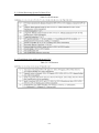
LIST OF TABLES
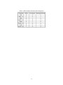
Table 2.1 Priority Phase Selections and Configuration .............................................................................. 15
Table B.1 Traffic Counts at Como and 29th Avenue................................................................................. B-1
Table D.1 Bus Route #3 Trip Counts........................................................................................................D-1
Table G.1 GGA Sentence .........................................................................................................................G-2
Table G.2 VTG Sentence ..........................................................................................................................G-2
LIST OF FIGURES
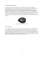
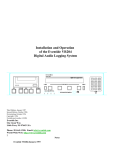
Figure 2.1 Puma PC/104 Plus Single Board Computer ................................................................................ 5
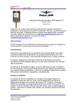
Figure 2.2 R104-88 Optoisolated Input and Relay Output Board ................................................................ 6
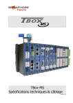
Figure 2.3 HE104 50 Watt High Efficiency PC/104 Power Supply ............................................................. 6
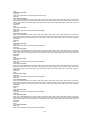
Figure 2.4 Denso DSRC Wireless Modem ................................................................................................... 7
Figure 2.5 Wireless Communications Using the Denso Radio..................................................................... 7
Figure 2.6 Ruckus Wi-Fi Modem ................................................................................................................. 7
Figure 2.7 Wireless Communications Using the Ruckus Modem ................................................................ 8
Figure 2.8 LinkSys Wireless-N USB Network Adapter ............................................................................... 9
Figure 2.9 Wireless Communications Using the WUSB-N Wireless Adapter ............................................. 9
Figure 2.10 Linksys Wireless-N Gigabit Wireless Router.......................................................................... 10
Figure 2.11 Wireless Communications Using the WUSB-N Wireless Adapter and Router ...................... 10
Figure 2.12 GPS and Wireless-Based Signal Priority System.................................................................... 11
Figure 2.13 The Embedded Signal Priority System Packaged in a NEMA Enclosure ............................... 11
Figure 2.14 Software Design of the Signal Priority System ....................................................................... 12
Figure 2.15 Eagle EPAC M40 Traffic Signal Controller............................................................................ 13
Figure 2.16 TSP Initiation Thrugh Serial or NTCIP Interface.................................................................... 13
Figure 2.17 Wiring Diagram from R104 I/O Board to Controller Cabinet................................................. 14
Figure 2.18 NEMA Phase Assignments ..................................................................................................... 14
Figure 3.1 An East-West Corridor Example for Signal Priority ................................................................. 16
Figure 3.2 Block Diagram of Transit Signal Priority Strategy ................................................................... 20
Figure 4.1 DSRC Wireless Coverage at 22nd and Franklin Avenue .......................................................... 21
Figure 4.2 Latency of DSRC Wireless Communication at 22nd and Franklin Avenue ............................. 22
Figure 4.3 DSRC Wireless Coverage at Como and 29th Avenue............................................................... 22
Figure 4.4 Latency of DSRC Wireless Communication at Como and 29th Avenue .................................. 22
Figure 4.5 Latency of 802.11x Wireless Communication at Como and 29th Avenue ............................... 23
Figure 4.6 Latency of Wireless Communication Using UMN Wi-Fi Network .......................................... 23
Figure 4.7 Preempt #5 Miscellaneous Menu .............................................................................................. 24
Figure 4.8 Preempt #5 Low Priority Menu ................................................................................................. 24
Figure 4.9 Low Priority Signal Priority Request ........................................................................................ 25
Figure 4.10 Program Eagle Traffic Signal Controller................................................................................. 25
Figure 4.11 Block Diagram of Signal Priority Request Simulation............................................................ 26
Figure 4.12 Transit Signal Priority Test Site .............................................................................................. 26
Figure 4.13 Aerial Map of Como and 29th Avenue SE in Minneapolis (from Google.com)..................... 27
Figure 4.14 Onboard Equipment Setup....................................................................................................... 27
Figure 4.15 Roadside Equipment Setup...................................................................................................... 28
Figure 5.1 Bus Receives Signal Priority ..................................................................................................... 29
Figure 5.2 Recorded GPS Data Point Along Como Ave. SE (Eastbound) ................................................. 30
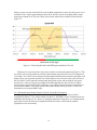
Figure 5.3 Vehicle Distance to Intersection and DSRC Wireless Coverage (Eastbound Test #1) ............. 30
Figure 5.4 Vehicle Speed Profile and TSP Request (Eastbound Test #1) .................................................. 30
Figure 5.5 Vehicle Distance to Intersection and DSRC Wireless Coverage (Eastbound Test #2) ............. 31
Figure 5.6 Vehicle Speed Profile and TSP Request (Eastbound Test #2) .................................................. 32
Figure 5.7 Recorded GPS Data Point Along Como Ave. SE (Westbound)................................................ 33
Figure 5.8 Vehicle Distance to Intersection and DSRC Wireless Coverage (Westbound)......................... 33
Figure 5.9 Vehicle Speed Profile and TSP Request (Westbound).............................................................. 34
Figure 5.10 Controller Data Collection Interface from SMART-SIGNAL Project.................................... 35
Figure 5.11 Establish Wi-Fi Connections ................................................................................................... 35
Figure 5.12 Wireless Data Communication through a 3rd Party Application ............................................ 36
Figure A.1 Como and 29th Avenue Geometry Layout and Phase Assignment ........................................A-1
Figure A.2 Signal Timing Data (from MarcNX Software).......................................................................A-2
Figure A.3 Intersection Data (from MarcNX Software)...........................................................................A-2
Figure B.1 Average Volume at Como and 29th Avenue .......................................................................... B-2
Figure C.1 EPM-5 Block Diagram (VersaLogic EPM-5 Reference Manual) .......................................... C-1
Figure C.2 EPM-5 Start Configuration (VersaLogic EPM-5 Reference Manual) .................................... C-2
Figure C.3 Connect Relay Output to Controller Cabinet.......................................................................... C-3
Figure C.4 R104 Digital I/O Relay Board Layout (Tri-M Engineering R104-88 User Guide) ................ C-4
Figure D.1 Map of Route #3 .....................................................................................................................D-2
Figure E.1 Denso DSRC Prototype........................................................................................................... E-1
Figure E.2 LinkSys Wireless-N USB Network Adapter........................................................................... E-1
Figure G.1 Garmin GPS 18 5Hz Unit .......................................................................................................G-1
Figure G.2 GPS Receiver Test Interface...................................................................................................G-3
EXECUTIVE SUMMARY
Current signal priority strategies implemented in various US cities mostly utilize sensors to detect
buses at a fixed or preset distance away from an intersection. Traditional presence detection systems,
ideally designed for emergency vehicles, usually send a signal priority request after a preprogrammed
time offset as soon as transit vehicles were detected without the consideration of bus readiness.
Significant amount of research projects focusing on various intelligent transportation systems (ITS)
applications under the Vehicle Infrastructure Integration (VII) framework have been investigated since
the introduction of the VII initiative. Data collected through the VII network could potentially enable
hundreds of possibilities including safety, mobility, and commercial uses, from intersection collision
avoidance and dynamic route guidance to road-level weather advisories and electronic toll collection.
Wireless communications systems have made rapid progress in the past decade and are commercially
available. Los Angeles County Metropolitan Transportation Authority (MTA) has implemented wireless
technology in a transit signal priority system along a corridor using the IEEE 802.11b protocol. The
wireless system on each bus sends an IP addressable message to an access point that covers three to four
intersections. A wireless client installed in the signal cabinet communicates with a modified traffic
controller to request signal priority. King County MTA in Washington is also planning to design wireless
TSP system similar to the implementation in LA County. Pace, a suburban bus division of the Regional
Transportation Authority, provides bus services throughout Chicago’s six-county suburban region. Pace
recently was awarded with several research projects to deploy bus rapid transit (Cermak, Golf Road, and
south suburban) and transit signal priority (Cicero Avenue and Rand Road) through the Safe,
Accountable, Flexible, Efficient Transportation Equity Act: A Legacy for Users (SAFETEA-LU) bill.
Pace is also working with a consulting company to identify wireless-based systems to provide bus signal
priority and to report priority status and system performance back to its transit operation center.
The objective of this study is to develop a wireless-based Transit Signal Priority (TSP) system that
will integrate the already installed Global Positioning System/Automated Vehicle Location (GPS/AVL)
system on the buses in Twin Cities. An adaptive signal priority strategy developed from phase I study was
incorporated to consider the bus schedule adherence, its number of passengers, location and speed. Buses
can communicate with intersection signal controllers using wireless technology to request for signal
priority. Similar setup can also be utilized for other transit-related ITS applications. The goals of the
phase 2 study are to evaluate the performance of DSRC (Dedicated Short Range Communication) and
Wi-Fi network, develop wireless communication prototype using commercial off-the-shelf (COTS)
products, implement adaptive TSP algorithm and validate the signal priority strategy based on the
AVL/GPS and wireless technology. The City of Minneapolis recently deployed wireless technology to
provide residents, businesses and visitors with wireless broadband access anywhere in the city.
Communication with the roadside equipment (e.g., traffic controller) for signal priority was tested using
the available 802.11x Wireless Local Area Network (WLAN) or the DSRC modems in vehicular
environment.
A set of PC/104 stand-alone Single Board Computer (SBC) was selected for the embedded system
development. Additional I/O modules were integrated to the embedded system to perform data
communication between traffic signal controller and roadside computer, and a transit vehicle and onboard
computer. A pair of 5.9-GHz Wireless Access in Vehicular Environment (WAVE) radio modules was
manufactured by DENSO Corporation (http://www.denso.co.jp/en/). The DSRC radio modems and
802.11x wireless adapters were utilized to establish wireless communications between the onboard
equipment (OBE) and the roadside equipment (RSE).
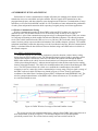
Performance of wireless communication is highly affected by the changing environment in which
transmission errors are unavoidable and quite common. Wireless signals suffer attenuations as they
propagate through space and other obstacles cause absorptions and reflections. Communication coverage
and latency were tested for both DSRC and 802.11x Wi-Fi modules at two different locations (East
Franklin Avenue at 22nd Avenue and Como Avenue at 29th Avenue in Minneapolis). The latency of DSRC
radio ranges from 3 to 6 milliseconds at both test sites. The latency of the University of Minnesota
(UMN) wireless network ranges from 10 to 30+ milliseconds depending on location. The DSRC modem
has potentially excellent performace with a high data communication rate; however, the availability of
DSRC is limited and we don’t know whether there will be national “rollout”. The Wi-Fi network has the
advantage of using existing infrastructure in Minneapolis; however, data latency and bandwidth need to
be considered. The wireless system evaluation helps us better understand the performance of each system
and potential constraints while requesting for signal priority in real-time application. Data communication
programs using User Datagram Protocol (UDP) were developed on a host machine and then later
downloaded to both roadside and onboard embedded computers.
Signal priority request output from roadside equipment was connected to a pre-emption input channel
on the signal controller inside the controller cabinet. Program in the traffic controller was also configured
and activated to accept external pre-emption inputs. The traffic signal controller was programmed by the
City of Minneapolis traffic engineer to specify corresponding delay, dwell, maximum call and extension
time. Developed prototype systems were deployed and tested at an intersection at Como and 29th Avenue
near the University of Minnesota campus to validate the bus signal priority algorithm using different
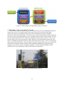
wireless communication protocols. The mobile design of the wireless transit signal priority system allows
us to test the prototype at different intersections and on different vehicles easily. The OBE was placed on
a test minivan with GPS receiver and radio antenna mounted on top of the vehicle to represent a transit
vehicle. The onboard embedded system interfaces with the GPS and wireless communication systems to
transmit vehicle location and other information (for example, vehicle ID, route ID, passenger counts, door
opening status and so on) to the roadside equipment. The RSE continuously monitors the vehicle location
when it travels within the range of the wireless communication and then generates a signal priority
request to traffic signal controller as needed.
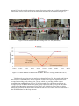
Field testing results show that the test vehicle successfully submitted a signal priority request through
the wireless communication as it is traveling toward the intersection instrumented with roadside
equipment. The test vehicle was initially traveling from a location outside the communication range of the
DSRC WAVE radios. As soon as the vehicle moved within the wireless communication range, the
adaptive signal priority algorithm began to monitor the location and speed of the test vehicle and
submited a request for priority through the roadside interface to the signal controller when the vehicle was
ready to enter the intersection. The Eagle EPAC traffic signal controller is capable of providing green
extension or red truncation (or early green) to the qualified or authenticated vehicle as it is approaching
the intersection. The signal priority request is dropped when the test vehicle passes the intersection or
when the duration of priority call exceeds the maximum call setting.
We also tested our signal priority systems using the Minneapolis Wi-Fi network. In 2006 the City of
Minneapolis signed a 10-year contract with USI Wireless of Minnetonka (http://www.usiwireless.com/)
to provide city-wide wireless broadband technology. According to the City of Minneapolis, the
Minneapolis wireless network will cover all 59 square miles of Minneapolis providing residents,
businesses and visitors with wireless broadband access anywhere in the city. The network will allow the
city to deliver services more efficiently and effectively. However, the current settings and configuration
of the Minneapolis Wi-Fi network would not allow direct TCP/UDP communications through their Wi-Fi
network between the OBE and RSE. Both OBE and RSE can receive dynamic IP addresses assigned
under the private network within the intranet connected to the wireless modems or adapters. The OBE or
RSE can freely communicate to the Internet through the Minneapolis Wi-Fi network individually.
However, the OBE cannot communicate with the RSE directly through the Wi-Fi network due to security
settings on the servers of USI wireless network. We were advised by the USI wireless technical support to
use third-party software to communicate between our onboard and roadside equipment through
Minneapolis Wi-Fi network. If a device on a private network needs to communicate with other networks,
a "mediating gateway" is needed to ensure that the outside network is presented with an address that is
real or publicly reachable so that Internet routers allow the communication. The mediating gateway is
typically a network address translation (NAT) device or a proxy server. Routers by default will forward
packets with RFC 1918 (http://tools.ietf.org/html/rfc1918) addresses. Unlike public Internet routers that
need additional configuration to discard these packets, internal routers do not need any additional
configuration to forward these packets. Someone may argue that latency of data communication between
the onboard system and the roadside system may increase significantly when introducing additional
software or the NAT gateway. However, variation of the network latency plays a more critical role than
the latency itself. Latency can be compensated for realtime application as long as the wireless network is
reliable.
Using the Minneapolis Wi-Fi network for TSP application can certainly reduce cost by taking
advantage of the existing infrastructure. However, availability of data bandwidth and quality of service,
concern of network reliability and data security need to be addressed when choosing the Wi-Fi
technology. The DSRC radio is potentially good with excellent performance (short range with fast data
communication rate), but the availability of DSRC is currently limited. We certainly don’t know whether
there will be national “rollout”. The UMN TSP system uses wireless technology to establish data
communication between transit vehicles and roadside systems. It is not limited to any particular wireless
technology.
This report documents the development, verification and validation of the embedded
signal priority prototype systems, field testing results and limitations of using the Minneapolis
Wi-Fi network for TSP. Detail documentations of the system design and integration are included
in the appendices.
1. INTRODUCTION
Transit Signal Priority (TSP) for transit has been studied and proposed as an efficient way to improve
transit travel & operation. Bus signal priority has been implemented in several US cities to improve
schedule adherence, reduce transit operation costs, and improve customer ride quality. Signal priority
strategies have helped reduce the transit travel time delay, as discussed in the literature (ITSA, 2002), but
the transit travel time reduction varies considerably across studies (Collura et. al, 2003). Signal priority
and preemption are often used synonymously; however, they are different processes. Signal preemption is
traditionally used for emergency vehicles (EV) or at railroad crossing. Preemption interrupts normal
intersection signal process to provide high priority for special events. Signal priority modifies the normal
signal operation in order to accommodate better service for transit vehicles (ITSA, 2004).
1.1 Background
Current signal priority strategies implemented in various US cities mostly utilized sensors to detect
buses at a fixed or at a preset distance away from the intersection. Signal priority is usually granted after a
preprogrammed time offset, after detection. Engineers have to adjust the detector location, receiver line of
sight and timing offset for each intersection in order to ensure its effectiveness. These TSP strategies do
not consider the bus’s speed and its distance from intersection when determining the appropriate time to
request signal priority. The proposed study would like to incorporate the GPS/AVL system on the buses
in Minneapolis and develop a signal priority strategy based on the bus’s timeliness with respect to its
schedule, number of passengers, location and speed of a bus.
Wireless communications systems have made rapid progress and are commercially available. Bus
information (e.g. speed, location, number of passengers, bus ID) can be transmitted wirelessly to a traffic
controller or to a regional Traffic Management Center (TMC) in making decisions for signal priority.
There are several wireless communication systems installed on each bus under the current Metro Transit
setup. An 800-MHz Motorola digital voice radio is used for communication between bus driver and
Transit Control Center (TCC). Another 800-MHz analog data radio is used to poll bus location and
passenger count data every minute. A Wireless Local Area Network (WLAN) 802.11x is also installed on
the bus. This is used to upload/download files between the bus and the TCC central server, when the bus
is within the proximity of the transit garage.
1.2 Research Objectives
We would like to provide effective signal priority to buses with minimal impact on other traffic using
the already equipped GPS/AVL system on the bus. The GPS system offers better information regarding
bus trajectory than the presence detection sensors previously used while requesting for traffic signal
priority. Our objective is to investigate the performance of GPS/AVL and deploy a wireless-based
adaptive signal priority strategy to provide reliable and efficient bus transit services with minimal impact
on traffic flow. Metro Transit buses currently equip with 800MHz data and voice radio and 802.11b/g
systems. We would like to utilize the existing systems with little or no additional hardware installation on
the buses for signal priority or other transit-related ITS applications. Communication with the roadside
unit (e.g., traffic controller) for signal priority can later be established using the DSRC (Dedicated Short
Range Communication) 802.11p protocol for wireless access in vehicular environment after the
implementation and deployment of the VII initiatives. The improved transit services will hopefully make
the transit system more attractive to the public and increase ridership. Simulation studies and field data
collection were conducted to estimate changes in bus travel time, delay, as well as potential impact on
other traffic.
1.3 Literature Review
The vision of the Vehicle Infrastructure Integration (VII) is to deploy a nationwide communications
network along the national roadways that enables communications between vehicles and roadside
1
infrastructure to improve transportation and quality of life. The report from Federal Highway
Administration (FHWA) documents the VII architecture and its design requirements (Farradyne, 2005).
Significant amount of research projects focusing on various intelligent transportation systems (ITS)
applications under the VII framework have been investigated since the introduction of the VII initiative.
Data collected through the VII network could potentially enable hundreds of possibilities including safety,
mobility, and commercial uses, from intersection collision avoidance and dynamic route guidance to
road-level weather advisories and electronic toll collection. For example, Wischhof et al. (2003) and
Zhang (2003) investigated the dissemination of vehicle-based traffic and travel information through the
VII network. Wu et al. (2005) evaluated the efficiency of message propagation between vehicles through
simulation. Xu et al. (2002) study the effect of vehicle vehicle/vehicle-roadside communication on the
performance of adaptive cruise control (ACC) systems through simulations. Collision avoidance
technologies that use the VII infrastructure are also being developed as part of the Cooperative
Intersections Collision Avoidance Systems (CICAS, http://www.its.dot.gov/cicas/index.htm) initiative.
Biswas et al. (2006) presented the concept of Cooperative Collision Avoidance (CCA) and its
implementation requirements in the context of the vehicle-to-vehicle wireless network. Alexander et al.
(2006) designed and deployed a transportable rural intersection surveillance system encompassing
RADAR (Radio Detection and Ranging), LIDAR (Light Detection and Ranging), camera systems and
wireless communications between infrastructure and vehicles to investigate the gap acceptance behavior
of drivers at rural intersections.
Wireless communications systems have made rapid progress in the past decade and are commercially
available. McNally et al. (2003) developed an in-vehicle, GPS-based system to provide real-time vehicle
guidance information through wireless communication technologies. Fitzmaurice (2005) reviewed the
recent technology advances and regulatory changes that have encouraged the mobile wireless applications
in rail and urban transit environments. Torrent-Moreno et al. (2004) investigated a study on the
probability of reception of a broadcast message by another car and how to provide priority access for
important warnings in 802.11-based vehicular ad-hoc networks (VANET). One of the key usages of
VANET is to support vehicle safety applications through the broadcast operations for informing the
immediate neighboring vehicles. Stibor et al. (2007) evaluated the number of communication partners in
communication range and maximum communication duration for a vehicular ad-hoc network using the
IEEE 802.11p transceivers in a highway scenario. Marca (2006) performed testing and benchmarked
possible throughput of 802.11b wireless communication technology for vehicle to roadside infrastructure
communications. Böhm et al. (2008) evaluated different wireless communication technologies, including
broadcast, cell based and dedicated short range technologies, and their effectiveness of transmitting roadsafety relevant information from infrastructure to vehicle (I2V) as part of the Co-operative Systems for
Intelligent Road Safety (COOPERS) program co-funded by the European Commission. Ahmed et al.
(2008) developed a blue tooth and wireless mesh networks platform for traffic network monitoring. The
platform uses traveling cars as data collecting sensors or probes and uses wireless municipal mesh
networks to transmit collected traffic data.
Los Angeles County Metropolitan Transportation Authority (LACMTA) has implemented wireless
technology in a transit signal priority system along several corridors using the IEEE 802.11b protocol
(Kittleson & Associates, 2006). The wireless system on each bus sends an IP addressable message to an
access point that covers three to four intersections. A wireless client installed in the signal cabinet
communicates with a modified traffic controller firmware to request for signal priority. TSP request was
sent wirelessly from bus onboard unit to an access point connected to traffic controller through a serial
(RS-232) interface. Bus messages and TSP responses from controller were also collected and sent to
central control via cellular communication. Iteris, Inc. (www.iteris.com) was recently selected by
LACMTA for the design, acquisition, deployment, and ongoing operation and maintenance of bus traffic
signal priority systems at 211 signalized intersections maintained by18 local agencies along Manchester
Boulevard, Garvey Boulevard/Cesar Chavez Avenue, and Atlantic Boulevard. King County MTA in
Washington is also planning to design wireless TSP system similar to the implementation in LA County.
2
Pace, the suburban bus division of the Regional Transportation Authority, provides bus services
throughout Chicago’s six-county suburban region. Pace recently awarded several research projects to
deploy bus rapid transit (Cermak, Golf Road, and south suburban) and transit signal priority (Cicero
Avenue and Rand Road) through the SAFETEA-LU bill (http://www.pacebus.com/sub/vision2020/
federal_projects.asp). Pace is working with a consulting company to identify a wireless-based system to
provide signal priority to buses and report status and performance back to the transit operation center.
Signal priority requests for transit or emergency vehicles can potentially be sent to the signal
controller through the vehicle-to-infrastructure communication architecture as described in VII
architecture (Farradyne, 2005). Signal priority for transit vehicles has been studied and proposed as an
efficient way to improve transit travel time and schedule adherence, to reduce transit operation costs, and
to improve customer riding quality. Signal priority strategies have helped reduce the transit travel time
delay, as discussed in the literature (ITS America, 2002), but the transit travel time reduction varies
considerably across studies (Collura et al., 2006). Unlike signal preemption, which interrupts the normal
intersection signal process to provide high priority for special events (emergency vehicle or railroad
crossing), transit signal priority (TSP) modifies the normal signal operation in order to accommodate
better service for transit vehicles (ITS America, 2004).
Transit signal priority has been implemented in several US cities (Seattle, Portland, Los Angeles, and
Chicago) as well as in Europe. Various technologies have been deployed for bus priority including
Opticom™ (St. Cloud, 2000), inductance loop detectors (Los Angeles), and RF tag (Seattle, King County,
2002). Recently, Crout (2005) at Tri-County Metropolitan Transportation District of Oregon (TriMet)
proposed two types of analyses (corridor and intersection level) to evaluate the effectiveness of the TSP
effort on transit operations over 300 signals implemented with signal priority. Current signal priority
strategies implemented in various US cities mostly utilize sensors to detect buses at a fixed or at a preset
distance away from the intersection. Signal priority is usually granted after a preprogrammed time-offset,
after detection. Engineers usually have to adjust the detector location, receiver line of sight and timing
offset for each intersection in order to ensure its effectiveness. Liu et al. (2004) presented a theoretical
model to quantitatively address the relation between bus detector location and effectiveness of transit
signal priority systems. Li et al. (2007) proposed an active signal priority optimization model for LightRail Transit (LRT) in a simulation study by estimating the train travel and dwell time. Most TSP
strategies do not consider the transit’s speed and its distance from the intersection when determining the
appropriate time to request signal priority.
Metro Transit in Twin Cities Metro area (http://www.metrotransit.org/) previously performed an
evaluation to provide signal priority for buses on Lake Street in Minneapolis using 3M Opticom™
systems. A special software modification was made to provide transit priority using green extension and
red truncation strategies. However, the Opticom™ system, ideally designed for emergency vehicle
preemption (EVP), was not able to adjust the trigger timing for buses approaching nearside bus stops, and
buses often missed the priority green period when they were ready to depart. Since several intersections
along Lake Street were already operating at their capacity, the potential for providing transit priority
without delaying vehicle traffic was somewhat constrained. There were also issues of buses traveling
across different municipalities that were unwilling to provide signal priority for transit. Results from this
previous evaluation study were not promising. With the installation of GPS system on its fleet, Metro
Transit now constantly monitoring bus locations in relation to their schedules, in order to provide more
reliable transit services and enhance transit operation and management. Bus location, travel time, delay
and other traffic information can also be collected and integrated to assist traffic operation management
and to inform the traveling public. Metro Transit would like to use the already installed GPS/AVL system
as the basis of a transit-based intelligent transportation system (ITS).
Bus information (e.g. speed, location, number of passengers, bus ID) can be transmitted wirelessly to
a traffic controller or to a regional Traffic Management Center (TMC) in making decisions to grant signal
priority request. Several wireless communication systems were installed on Metro Transit buses as
standard system configuration. An 800-MHz Motorola digital voice radio is used for communication
between bus driver and Transit Control Center (TCC). Another 800-MHz analog data radio is used to poll
3
bus location and passenger count data every minute. A Wireless Local Area Network (WLAN) 802.11x is
also installed on the bus to automatically upload or download data files between the bus computer and the
central server at TCC when the bus is within the proximity of the transit garage.
Researchers at California PATH (Partners for Advanced Transit and Highways) studied an “Adaptive
Bus Signal Priority” (ABSP) to apply an active priority strategy for buses, by including bus GPS
information, traffic detector data, and a travel-time predictor to an adaptive model (Liu et al., 2003).
Wadjas and Furth (2003) developed a methodology by adapting advanced detection and cycle length to
provide transit signal priority. The adaptive control includes traffic density and queue length estimation in
a simulation study. Skabardonis and Geroliminis (2008) developed an analytical model for real-time
estimation of arterial travel time. A signal priority algorithm, extends the active signal priority strategy
initially proposed by Skabardonis (2000), was developed and incorporated into their base model to
provide system wide adjustments to the signal timing plans and priority based on the real-time traffic
information. Li et al (2005) proposed a heuristic TSP algorithm to provide signal priority to buses as well
as limit negative impact on cross-street traffic. Traditional TSP strategies implemented in United States
are mostly fixed-location detection systems and implemented with time-of-day signal control systems.
TSP systems using fixed-location detection usually do not work well with nearside bus stops, due to the
uncertainty in bus dwell time. Zheng et al. (2007) developed a theoretical model to estimate the
corresponding delays at nearside bus stops. Kim and Rilett (2005) proposed a weighted least squares
regression model in simulation to estimate bus dwell time in order to overcome nearside bus stop
challenges. Ghanim et al. (2007) developed an artificial neural network modeling tool to predict
intersection bus arrival time on approaches with nearside bus stops. Rakha et al. (2006) performed field
and simulation evaluation along US Route 1 corridor. They recommended further consideration on
existence of queues in transit signal priority strategy and suggested no near-side bus stop implementation.
Furth and SanClemente (2006) investigated the impact of bus stop location on bus delay. They found farside bus stops cause small reduction in delay or no effect. Nearside bus stops more often increase bus
delay.
A bus priority algorithm could also be integrated into an adaptive intersection signal control model.
Research based on the bus priority facilities available within the Split Cycle Offset Optimization
Technique (SCOOT) traffic signal control system was conducted by Bretherton et al. (1996). Traffic
signal priorities can be controlled by a central SCOOT computer or by a local traffic signal controller. A
local controller can achieve faster TSP response to buses than a centralized control. Different strategy
options for providing bus priority at signals are compared by McLeod & Hounsell (2003) using the
simulation model called Selective Priority to Late buses Implemented at Traffic signals (SPLIT). McLeod
suggested that differential (conditional) priority strategies (e.g. granting priority for lateness) give the best
results, as these provide a good balance between travel time and passenger waiting time. Furth and
Mueller (2000) conducted a field study with three priority conditions (no priority, absolute priority, and
conditional priority) at a transit route in the Netherlands. The study found absolute priority caused large
delays to other traffic while conditional priority caused little, if any additional delay. Dion and Rakha
(2005) developed a simulation approach to integrate TSP within an adaptive traffic control system. They
evaluate three different signal control scenarios and found adaptive signal control reduced negative
impacts on general traffic while providing signal priority to buses. Recently, Mirchandani & Lucas (2004)
developed a Categorized Arrival-based Phase Reoptimization at Intersection (CAPRI) strategy that
integrates transit signal priority within a real-time traffic adaptive signal control system, called RHODES
(Real-time Hierarchical Optimized Distributed Effective System, 2001). “Weighted bus” and “phase
constrained” approaches were developed for providing transit priority through the RHODES-CAPRI
framework. Mirchandani et al. (2001) proposed a hierarchical optimization approach where traffic signals
are determined by considering delays of all vehicles on the network as well as bus passenger counts and
schedule while providing transit priority (RHODES/BUSBAND).
4
2. WIRELESS TRANSIT SIGNAL PRIORITY (W-TSP) SYSTEMS
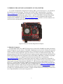
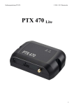
A set of PC/104 stand-alone Single Board Computer (SBC), as shown in Figure 2.1, was selected for
the embedded system development. The Puma series (EPM-5) SBC, manufactured by VersaLogic
(http://versalogic.com/) and additional I/O modules were integrated to perform data communication
between traffic signal controller and a transit vehicle. A pair of 5.9GHz DSRC (Dedicated Short Range
Communications) prototypes, WAVE (Wireless Access in Vehicular Environment) radio modules
manufactured by DENSO Corporation (http://www.denso.co.jp/en/) and 802.11x wireless modems were
used for wireless communications between the embedded computers.
Figure 2.1 Puma PC/104 Plus Single Board Computer
2.1 Embedded Computers
The Puma SBC features the AMD GX 500 processor, which offers 500 MHz equivalent performance
while drawing only one watt of power. This highly-integrated processor provides extremely fast on-board
transfers (6 GB per second), high-speed memory access. The Puma can operate as a stand-alone SBC or
can be combined with specialized PC/104 or PC/104-Plus I/O boards for additional functionality. Passthrough connectors for the PC/104 and PC/104-Plus interfaces provide support for many off-the-shelf I/O
boards. Block diagram and start configuration of the Puma (EPM-5) SBC board is included in Appendix
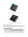
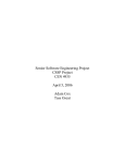
C.1. As shown in Figure 2.2, a digital I/O board R104-88, manufactured by Tri-M Systems
(http://www.tri-m.com/) includes 8 isolated inputs and 8 relay outputs. It is added to the Puma SBC to
interface with traffic controller cabinet for signal priority request. Detail board layout and jumper settings
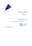
of the R104 I/O board are documented in Appendix C.2. A HC104 power supply module, as shown in
Figure 2.3, is stacked under the single computer and IO module to provide 5 and 12VDC power through
the pass-through connectors. The Puma SBC offers a CompactFlash (CF, http://www.compactflash.org/)
socket to allow removable media storage and support bootable media. Linux (www.linux.org/) kernel for
each embedded computer is built on a Linux host machine which compiles and creates a bootable Linux
OS image on a CompactFlash disk of less than 1 Gigabyte. Detail instructions on building a Linux kernel
on a CompactFlash disk are discussed in Appendix C.3.
5
Figure 2.2 R104-88 Optoisolated Input and Relay Output Board
Figure 2.3 HE104 50 Watt High Efficiency PC/104 Power Supply
2.2 Wireless Communication Modules
Buses can communicate with intersection signal controllers using wireless technology to request for
signal priority. Communication between the RSE and OBE can be tested using the 802.11x WLAN or the
DSRC (Dedicated Short Range Communication) 802.11p protocol currently under development for
wireless access to and from the vehicular environment.
2.2.1 Denso WAVE Radio Modems
A pair of Denso DSRC radio modems, as shown in Figure 2.4, was previously purchased by
Intelligent Vehicles Laboratory (http://www.its.umn.edu/ProgramsLabs/IntelligentVehicles/) for
research on vehicle to vehicle communications (for example, electronic braking). The Denso radio
modems were early prototypes operating at 5.9GHz using the 802.11b protocol. Each onboard and
roadside computer was connected to a Denso modem for wireless data communications. The data
flow chart of the wireless communications between the roadside and onboard equipments using the
Denso radio modems is displayed in Figure 2.5. The communication distance of the DSRC modems
6
ranges around 300 meters (1000 ft). The direct point to point configuration of communication
provides relatively high speed of data communication.
Figure 2.4 Denso DSRC Wireless Modem
Figure 2.5 Wireless Communications Using the Denso Radio
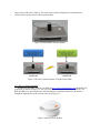
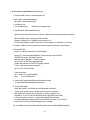
2.2.2 802.11x Wireless Modules
In addition to the DSRC modems, two Ruckus (http://www.ruckuswireless.com/) MediaFlex WiFi modems, as shown in Figure 2.6, was used to access to the Minneapolis wireless network. The
RSE and OBE were each connected to a Ruckus modem to establish connection to the Internet
through the Minneapolis Wi-Fi network as shown in Figure 2.7.
Figure 2.6 Ruckus Wi-Fi Modem
7
Figure 2.7 Wireless Communications Using the Ruckus Modem
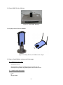
Since Minneapolis wireless network does not cover the University of Minnesota (UMN) campus
area, a pair of LinkSys (http://www.linksys.com/) Wireless-N USB adapters, as shown in Figure 2.8,
was also used during the development phase to test the wireless communication systems using the
University of Minnesota wireless network from the lab. The RSE and OBE were each connected to a
adapter to establish connections through the UMN wireless network as shown in Figure 2.9. USB
wireless adapters are usually plug and play after installing the device drivers in Windows operation
system. However, many vendors do not release specifications of the hardware or provide a Linux
driver for their wireless network cards. An NDISwrapper (http://ndiswrapper.sourceforge.net/joomla/)
open source project implements Windows kernel Application Programming Interface (API) and
Network Driver Interface Specification (NDIS) API within Linux kernel. A Windows driver for
wireless network card is then linked to this implementation so that the driver runs natively, as though
it is in Windows, without binary emulation. With the NDISwrapper, most miniPCI (builtin), PCI,
PCMCIA (Cardbus only) or USB wireless network cards work in Linux with x86 or x86-64.
Although NDISwrapper is intended for wireless network cards, other devices are known to work
according the NDISwrapper project website: for example, Ethernet cards, USB to serial port device,
home phone network device and so on.
In order to keep the Linux kernel to a minimal size and allow the system to be bootable from a
CompactFlash memory, no Graphical User Interface (GUI) was installed on the Linux-based
embedded target systems. A text-based web browser called Lynx (http://lynx.isc.org/) was then
installed on the embedded computer to submit authentication scripts and passphrases to the University
of Minnesota wireless network or the Minneapolis Wi-Fi network when using the USB wireless
adapters. The Ruckus modems do not require additional authentication to access the Minneapolis WiFi network since the Media Access Control (MAC) addresses on the Ruckus modems were previously
registered to the Minneapolis Wi-Fi network server. Dynamic Host Configuration Protocol (DHCP)
was used to obtain IP address dynamically when the wireless modem detects the network access
point. Detail information regarding the NDIS wrapper for the wireless adapter and the lynx text-based
web browser are documented in Appendix E.
8
Figure 2.8 LinkSys Wireless-N USB Network Adapter
Figure 2.9 Wireless Communications Using the WUSB-N Wireless Adapter
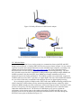
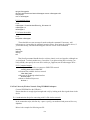
2.2.3 Wireless Router
Another configuration for our wireless testing is to communicate between the RSE and OBE
though a private network. A LinkSys WRT310N wireless router as shown in Figure 2.10 was used as
a gateway to test the data communication between the embedded target computers. According to the
product specification from LinkSys (http://www.linksys.com/), the access point built into the
WRT310N router uses the Wireless-N (draft 802.11n) wireless networking technology. The IEEE
802.11n builds on previous 802.11 standards by adding multiple-input multiple-output (MIMO) and
40 MHz operation to the physical (PHY) layer. MIMO uses multiple transmitter and receiver
antennas to improve the system performance. The 40 MHz operation uses wider bands, compared to
20 MHz bands in previous 802.11 operations, to support higher data rates. Wider bandwidth channels
are cost effective and easily accomplished with moderate increases in digital signal processing.
By overlaying the signals of multiple radios, WRT310N router's MIMO technology multiplies the
effective data rate. Unlike ordinary wireless networking technologies that are confused by signal
reflections, MIMO actually uses these reflections to increase the range and reduce "dead spots" in the
wireless coverage area. The robust signal travels farther, maintaining wireless connections much
farther than standard Wireless-G. The Wireless-N USB adapters were used to evaluate the
performance of the wireless router in the outdoor environment. The RSE and OBE were each
connected to the wireless-N adapters and established communications to each other through the
WRT310N access point as illustrated in Figure 2.11.
9
Figure 2.10 Linksys Wireless-N Gigabit Wireless Router
Figure 2.11 Wireless Communications Using the WUSB-N Wireless Adapter and Router
2.3 Wireless Signal Priority System Integration
System integration of the embedded TSP system and software design and development are the key
elements in developing the wireless signal priority system as shown in Figure 2.12. The design of the
OBE includes the wireless communication modules and the interfaces to the GPS receiver and other
transit vehicle information such as passenger count and door opening status. The RSE include the signal
priority algorithm, wireless communication module and the interface to traffic signal controller.
2.3.1 Hardware Design and Integration
A Garmin GPS 18 5Hz unit is used provide vehicle location as part of the wireless transit signal
priority system. The GPS 18 receiver stores configuration information in its non-volatile memory
which allows the GPS unit to start up quickly. It also has a real-time clock and raw measurement
output data for sophisticated, high-precision dynamic applications. For extra precision, it offers 5 Hz
measurement pulse output with rising edges that align to precise 0.2 second increments of UTC time,
as long as the receiver has reported a valid and accurate position within the past 4 seconds. Graphical
User Interface (GUI) was previously developed to test the performance of the GPS 18n unit. Detail
information about the Garmin GPS receiver is included in Appendix G.
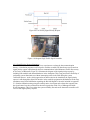
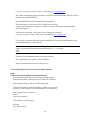
The mobile embedded signal priority system is packaged in a NEMA enclosure, as shown in
Figure 2.13. This design allows us to easily deploy the prototype system to various field testing and
validation at different intersections or on different buses. The wireless signal priority strategy will be
tested using the Minneapolis Wi-Fi network and the 5.9 GHz DSRC radio. Detail testing results are
discussed in Chapter 4.
10
Traffic
Controller
VID, # Passenger, Stop Location,
Bus Schedule, Door Status, etc.
Antenna
Modem
Tx/Rx
Antenna
Modem
Tx/Rx
GPS Receiver
GPS/AVL
I/O
Ex. Door Open/Close
APC
Onboard
Equipment
(OBE)
UMN
TSP
Processor
Figure 2.12 GPS and Wireless-Based Signal Priority System
Figure 2.13 The Embedded Signal Priority System Packaged in a NEMA Enclosure
2.3.2 Software Design and Implementation
Software design of the OBE includes three major processes, GPS string processing, OBE wireless
communications, and bus computer interface as shown in Figure 2.14. The GPS data processor parses
the GPS sentences every 200 ms since the GPS receiver updates its location five times per second.
Software design of the OBE includes the signal priority algorithm, RSE wireless communications,
11
traffic controller interfaces. The signal priority algorithm developed in the phase one simulation study
was ported to the host machine, recompiled and downloaded to the target computers for testing.
Transmission Control Protocol (TCP) is optimized for accurate delivery rather than timely
delivery, TCP sometimes incurs relatively long delays (in the order of seconds) while waiting for outof-order messages or retransmissions of lost messages, and it is not particularly suitable for real-time
applications. The User Datagram Protocol (UDP) does not guarantee reliability or ordering in the way
that TCP does. UDP, faster and more efficient, is suitable for time-sensitive applications that do not
need guaranteed delivery. UDP is used to establish the data communication between the OBE and
RSE.
UDP uses a connectionless communication setup. A process using UDP does not need to
establish a connection before sending data and when two processes stop communicating there are no,
additional, control messages. Communication consists only of the data segments themselves. A
network node can communicate with another network node using UDP without first negotiating any
kind of handshaking or creating a connection. Because of this, UDP is very efficient for protocols that
send small amounts of data at irregular intervals. UDP provides a message-oriented interface. Each
message is sent as a single UDP segment, which means that data boundaries are preserved. However,
this also means that the maximum size of a UDP segment depends on the maximum size of an IP
datagram. More detail information regarding the UDP protocol can be found at Internet Engineering
Task Force (IETF, http://www.ietf.org/rfc/rfc768.txt).
Figure 2.14 Software Design of the Signal Priority System
2.4 Signal Control Interface
Signal priority request is sent from the RSE to the signal controller through the digital I/O board. The
traffic signal controller needs to be programmed and configured to accept the external input for priority
requests. Priority phase assignments and bus route information are also needed to help RSE determine
where is bus coming from and which phase to provide green extension or red truncation.
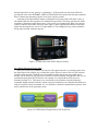
2.4.1 Signal Priority
The Eagle EPAC traffic controller, as shown in Figure 2.15, includes provisions for internal
preemptors with the capability of handling six unique preempt sequences. The preemption program
accepts commands from 6 preempt inputs and provides the timing and signal display programmed to
occur in response to each. Preemption controls are internally applied. Internally applied preempt
controls will have priority. Each preempt input provides two modes of priority control based on the
form of the input signal. The standard input form is a continuous ground true logic input. The
12
alternate input form, for low priority, is a pulsating (1~30 Hz) ground true logic input. When the
preempt link value in the PREEMPT→MISCALLENAEOUS menu equals to the preempt command,
then a constant input actuation will place a call for low priority routine.
According to the Eagle SEPAC manual, enabling the low priority routine will insert a delay of
500 milliseconds into the recognition of a standard preempt routine. This delay will allow the traffic
controller to determine whether the request is a low priority or preemption call. When a low priority
routine is enabled, the preempt call for the same input is a pulse signal and the duration of the pulse
signal must be longer than 1 second. Preempt channel #5 was configured as low priority channel to
accept inputs from the roadside computer.
Figure 2.15 Eagle EPAC M40 Traffic Signal Controller
2.4.2 Wiring Diagram of Priority Input
There are several ways to initiate TSP request on the signal controller. An external request from
the digital input is the simplest way to initiate the request. However, there will be no TSP responses
from the signal controller. The RSE has no information whether the request was granted or not.
Another way to initiate the TSP request is to interface with the controller serial interface (RS-232) or
communicate through the NTCIP interface (for example, Los Angeles Metro TSP project) as
illustrated in Figure 2.16. TSP reuqets were sent directly to the controller using the proprietary
commands. Signal controller firmware usually needs to be modified by the controller manufacturer in
order to accept the external commands. It is very difficult to obtain the communication protocol of the
traffic controller due to the proprietary nature.
Figure 2.16 TSP Initiation Thrugh Serial or NTCIP Interface
13
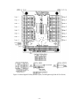
Wiring diagram of a single preemption channel is illustrated in Figure 2.17. Two wires from the
normally closed output of the R104 digital I/O board were connected to the preemption input and the
24VDC logic common, respectively. NEMA controllers require a standard 6.25 Hz signal at 50%
duty cycle, for the low priority input logic circuits and a ground true logic for the high priority or
preemption. A continuous 6.25 Hz pulse signal (low-priority call) for transit vehicle priority calls was
generated from the RSE when bus is ready to pass through upcoming intersection.
Figure 2.17 Wiring Diagram from R104 I/O Board to Controller Cabinet
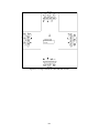
2.4.3 Priority Phase Selection and Configuration
A priority phase selection table is configured in the RSE to determine which phase and in what
direction will the transit vehicle need signal priority. The standard NEMA phase assignment for a
main street in east/west direction is shown in Figure 2.18. Sample priority phase selections and
configuration is shown in Table 2.1 where the I/O channels and priority inputs are specified.
Figure 2.18 NEMA Phase Assignments
14
Table 2.1 Priority Phase Selections and Configuration
15
3. ADAPTIVE TRANSIT SIGNAL PRIORITY STRATEGY
To illustrate our priority strategy, consider a simple eastbound/westbound corridor as shown in Figure
3.1. For a bus approached a bus stop or signalized intersection, there are basically two scenarios, a
nearside bus stop or a far-side bus stop. For the nearside bus stop, a bus will stop for boarding/alighting
before passing the signalized intersection, as illustrated in Figure 3.1 by the eastbound bus approaching
stop j and intersection i. Estimated bus dwell time at the nearside bus stop needs to be considered by the
signal controller to provide signal priority to the bus in a timely manner. For the far-side bus stop, a bus
passes through the intersection first before its arrival at the stop (see Figure 3.1 westbound bus
approaching intersection i and bus stop k). Bus travel time to the intersection needs to be considered when
providing priority.
Figure 3.1 An East-West Corridor Example for Signal Priority
3.1 Bus Stop Location Consideration
3.1.1 Nearside Bus Stop
Consider the bus traveling in the eastbound as shown in Figure 3.1. Expected bus dwell time, Tdj ,
at bus stop j can be forecasted using historical dwell time statistics. Expected bus travel time, Taj ,
from its current location to bus stop can be calculated via,
Taj =
d e, j
vb
+ Tbr + Tdelay
(Eq. 1)
Where,
v b : is bus speed,
d e , j : is the distance from the current bus location to bus stop j,
Tbr : is bus braking/stopping time, and
Tdelay : is the traffic delay on bus route.
The expected bus travel time ( T ji ) from bus stop j to intersection i can also be calculated as
follows, assuming the distance from the nearside bus stop to the intersection is relatively short
compared to the distance needed to accelerate to running speed.
16
T ji =
2( d e ,i − d e , j )
a
+ Tbc
(Eq. 2)
Where,
d e,i : is the distance from eastbound bus to intersection i,
d e , j : is the distance from eastbound bus to bus stop j,
a : is the bus acceleration, and
Tbc : is the bus clearance time.
Therefore the predicted time at which the eastbound bus passes intersection i can be calculated as
follows.
tˆei = t + Taj + Tdj + T ji
(Eq. 3)
Where,
t : is the current time, sec.
And estimated time for the bus leaving stop j is,
tˆlj = t + Taj + Tdj
(Eq. 4)
The desired signal priority request should then be sent at
δ n seconds prior to the bus departure
time at stop j. That is, at time tˆlj − δ n , where
δ n = t cp + t comm + t const
(Eq. 5)
t cp : is the controller processing time,
t comm : is the communication latency time, and
t const : is an additional time constant.
The signal priority service should be ended at tˆei + Txi , where Txi is the time for the bus to cross
intersection i. If both beginning ( tˆlj − δ n ) and ending ( tˆei + Txi ) of the estimated priority service fall
within the green split, no action needs to be taken at the controller. If tˆlj − δ n falls in the green split
and tˆei + Txi falls in the red split, extended green time is needed to ensure that bus could pass the
intersection. However, if the estimated beginning of priority service time ( tˆlj − δ n ) falls within the
red light period, red signal truncation or early green light treatment is needed to provide bus signal
priority.
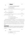
3.1.2 Far-side Bus Stop
For a bus approaching an intersection prior to its arrival at next bus stop, for example, the bus
traveling in westbound as shown in Figure 3.1, signal priority should be provided based on bus
traveling speed and traffic conditions. The estimated time ( Tai ) to arrive at intersection i can be
calculated as,
Tai =
d w ,i
vb
+ Tdelay
(Eq. 6)
Where,
d w ,i : is the distance from westbound bus to intersection i,
v b : is bus speed, and
Tdelay : is the traffic delay on bus route.
17
Therefore the estimated time for westbound bus passing intersection i can be calculated as
follows.
(Eq. 7)
tˆwi = t + Tai
Where,
t : is the current time, sec.
The desired signal priority would need to begin at δ n seconds prior to the bus arriving
intersection i ( tˆwi − δ n ), where
δ n is defined as equation (5). The signal priority service can be ended
at tˆwi + Txi , where Txi is the time for bus to cross intersection i. If both beginning ( tˆwi − δ n ) and
ending ( tˆwi + Txi ) of the estimated priority service fall within the green split, no action needs to be
taken by the controller. If tˆwi − δ n falls in the green split and tˆwi + Txi falls in the red split, extended
green time is need to ensure bus could pass the intersection. However, if the estimated beginning of
priority service time ( tˆwi − δ n ) falls within the red light period, red signal truncation or early green
light treatment is needed to offer bus priority.
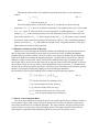
3.2 Estimation of Bus Dwell Time at Bus Stop
Ghanim et al. (2007) developed an artificial neural network modeling tool to predict the bus arrival
time on approaches with nearside bus stops based on observed travel time, boarding and alighting
demand, and current traffic condition. We used a simpler linear regression model to predict dwell time
based on the number of boarding and alighting passengers, average headway between buses, schedule
adherence, number of door on the vehicle, fare collection method, and bus type. Estimated passenger
arrival rates will be used to forecast bus dwell time at each stop. Based on the collected data, we assume
the passenger arrivals at each stop follow a Poisson distribution with an arrival rate, λ , calculated from
the mean of the collected passenger arrival rate. A Poisson process subroutine was developed to generate
numbers of passengers boarding and alighting at each stop during the simulation.
Bus dwell time at a bus stop for boarding can be estimated using the following equation.
TdjB = λ j (t ) × [tk ( j ) − tk −1 ( j )] × Tboarding
(Eq. 8)
Where,
TdjB is the bus dwell time for boarding at stop j,
λ j (t ) is the passenger arrival rate for stop j,
tk ( j ) is the arrival time of bus k at stop j,
tk −1 ( j ) is the arrival time of bus k-1 at stop j, and
Tboarding is the average boarding time per passenger.
3.3 Priority Acknowledgement Rules
After receiving a signal priority request from a bus, the signal controller has to determine whether or
not to grant the request. Only one bus will get the priority service if there are multiple requests at the
same intersection from buses on different approaches. The signal controller will ignore all bus priority
requests if there is an emergency vehicle preemption request. The signal controller will consider the
following three components when determining which bus will receive the priority service.
18
3.3.1 Priority Request Time, Time Factor (TF)
⎧ A = WT , B = 1 t A < t B
TF ( A, B ) = ⎨
⎩ A = 1, B = WT t A > t B
Bus A wins if it requests earlier than bus B does, where WT is the request time weighting factor
( WT ≥ 1 ).
3.3.2 Bus Schedule Adherence, Lateness Factor (LF)
LF = WL × TLate
Where WL is the bus late time weighting factor ( WL ≥ 1 ) and TLate is the number of minute the bus
was late. LF = 0 when bus is ahead of its schedule.
3.3.3 Number of Passengers, Passenger Factor (PF)
PF = WP × N passenger
Where WP is the bus passenger count weighting factor ( WP ≥ 1 ) and N passenger is the number of
passengers on the bus.
The priority acknowledgement functions for bus A and B are defined as follows.
f ( A) = TF ( A, B ) × {LF ( A) + PF ( A)}
f ( B ) = TF ( A, B ) × {LF ( B ) + PF ( B )}
(Eq. 9)
If the priority acknowledgement function, f(A) is greater than f(B), bus A will be granted signal
priority. No signal priority request is granted if the acknowledge function f equals zero, which means
there are no passengers on the bus and no delay on bus schedule adherence.
3.4 Signal Timing Treatment
The projected signal phase estimated arrival time for a bus passing a signalized intersection can be
calculated using the equations discussed in the previous section. When the projected signal phase
coincides with the priority phase, which is the phase where a bus requires passing through an intersection,
green extension is considered if the remaining green time is insufficient. However, if the projected
arriving phase is different from the priority phase, phase arrangement, such as phase suppression or red
truncation, is needed to provide green time to the buses. A minimum green time has to be served prior to
terminating the phase.
There has been some concern about returning the intersection timing to its original coordination after
providing signal priority to buses. Some priority strategies require many cycles before the signal timing is
resynchronized to its regional coordination (Siemens 2002). Recently, an advanced controller provides the
signal priority recovery with a cycle by including optional transit phases in the timing plan (Siemens).
The bus signal priority strategy will resynchronize to its neighbor intersections in the next cycle by
reducing the amount of green time extended in the next cycle priority phase. Signal priority requests in
the following cycle will be ignored in order to facilitate coordination recovery. For example, if the request
from bus A or B in cycle i was granted at an intersection, priority requests from bus C and D will not be
considered because cycle i+1 will be used for coordination recovery.
19
3.5 Signal Priority Implementation
The priority strategy was implemented using the C programming language and compiled on a Linux
host machine. Executable binary code was then downloaded to each OBE and RSE. When a bus travels
within the wireless communication range, the signal priority program will continuously monitor the bus
location and speed. Bus location and its distance corresponding to the next bus stop and signalized
intersection were calculated to identify a nearside versus a far side bus stop scenario. The control diagram
for the priority strategy is shown in Figure 3.2. Bus dwell time at each stop was computed based on the
passenger arrival using the Poisson distribution. Bus travel times to the intersection and the bus stop were
calculated to determine when to submit priority request prior to its arrival at the signalized intersection.
Signal priority settings in the controller were programmed to provide green extension or red truncation.
The EPAC controller is running on a background coordination cycle to ensure that the intersection returns
back to its timing and stays coordinated with the neighboring intersections.
Figure 3.2 Block Diagram of Transit Signal Priority Strategy
20
4. EXPERIMENT SETUP AND TESTING
Performance of wireless communication is highly affected by the changing environment in which
transmission errors are unavoidable and quite common. Wireless signals suffer attenuations as they
propagate through space and other obstacles cause absorptions and reflections. Communication coverage
and latency were tested for both DSRC and 802.11x Wi-Fi modules to better understand the performance
of each system and potential constraints while requesting for signal priority in real-time applications.
4.1 Wireless Communication Testing
Wireless communication testing for Denso DSRC radios and Wi-Fi module were tested at two
different test sites, East Franklin Avenue at 22nd Avenue and Como Avenue at 29th Avenue in
Minneapolis. A pair of data communication programs using User Datagram Protocol (UDP) were written
in C language and running on both roadside and onboard embedded computers. The onboard computer
receives the vehicle location from the GPS receiver every 200 ms (5 Hz) and sends vehicle ID, passenger
counts, location, priority request and other information to the roadside computer wirelessly. The roadside
equipment immediately returns the data string received from onboard computer. Wireless communication
latency is calculated from the time difference between the data string sent to RSE and received back on
the onboard computer.
4.1.1 DSRC Communication Latency
As shown in Figure 4.1, the roadside equipment is placed at location A where latency testing
begins along the East Franklin Avenue. The onboard equipment is placed inside a passenger vehicle.
The onboard computer continuously sends out UDP data to the roadside unit through the Denso
DSRC radio modem as the vehicle traverses from location A to B then turns around at B. The test
vehicle passes through location C, and turns around again at location D then returns back to starting
location A through location E. The vehicle lost communication nearby location B and during the CDE
curve. The UDP protocol allows the vehicle to re-establish the communication with roadside
computer as soon as it enters the wireless communication coverage range. Wireless signal coverage of
the DSRC radio and vehicle GPS data were plotted in Figure 4.1 where X and Y represent the
coordinate of the Stake Plane Coordinate System (SPSC) of Minnesota South FIPSZONE 2203. The
wireless communication distance of the DSRC radio is about 650 meters (or 325 m radius) at 22nd
Ave and East Franklin Avenue.
Figure 4.1 DSRC Wireless Coverage at 22nd and Franklin Avenue
The average wireless data communication latency using the Denso DSRC radio ranges between 4
and 6 milliseconds as shown in Figure 4.2. The onboard computer lost it UDP data packets
periodically around 39:44. The wireless link was totally lost between 40:05 and 40:10.
21
Figure 4.2 Latency of DSRC Wireless Communication at 22nd and Franklin Avenue
Similar testing was performed at the intersection of Como and 29th Avenue to compare the
performance of DSRC radio at different location. As shown in Figure 4.3, the wireless coverage range
at Como test site is much shorter than that at Franklin Avenue. The shorter communication range was
probably caused by the significant amount of trees along the Como Avenue which might contribute
additional reflections, absorptions and refractions. The average wireless data communication latency
using the Denso DSRC radio ranges between 3 and 5 milliseconds as shown in Figure 4.4 at Como
and 29th Avenue.
Figure 4.3 DSRC Wireless Coverage at Como and 29th Avenue
Figure 4.4 Latency of DSRC Wireless Communication at Como and 29th Avenue
22
4.1.2 802.11x Wi-Fi Communication Latency
Additional testing was also conducted using the Wi-Fi adapter through a LinkSys WRT310N
router at Como test site. The average wireless data communication latency using the Linksys
Wireless-N adapter is about 23 milliseconds as shown in Figure 4.5. Test vehicle initially established
wireless communication with the RSE at 55:35. As the vehicle travelled away from the RSE, the OBE
lost connection between 56:05 and 56:38. Wireless communication was re-established as the test
vehicle turned around and traveled within the wireless coverage distance. The coverage distance of
the Wi-Fi system is about 100 meters.
Figure 4.5 Latency of 802.11x Wireless Communication at Como and 29th Avenue
The wireless prototype system was also tested using the University of Minnesota (UMN) Wi-Fi
network. The average wireless data communication latency using the Linksys Wireless-N adapter
(WUSB300) is about 15 milliseconds as shown in Figure 4.6. Wireless communication was
established as long as the test vehicle stays within the area covered by the wireless network.
Figure 4.6 Latency of Wireless Communication Using UMN Wi-Fi Network
4.2 Program Signal Controller and Signal Priority Interface
Output of the signal priority request from the roadside computer was connected to the pre-emption
input channel on the signal controller through wirings in the controller cabinet. Traffic signal controller
was configured and activated to accept external pre-emption inputs. The traffic signal controller was
23
programmed by the City of Minneapolis traffic engineer to specify corresponding delay, dwell, maximum
call, and extension time.
4.2.1 Program Low Priority Pre-Emption Input
Traffic signal at the intersection of Como and 29th Avenue is controlled by an Eagle M10 NEMA
traffic controller housing in a P-type cabinet. The NEMA controller allows up to six pre-empt inputs
from external calls. Each pre-emption input can operate in high or low priority mode. Preemption
input #5 in low priority mode was configurred to provide green extension or red truncation to the
main street (Como Ave.) in signal phase 2 and 6 for our field testing. The low priority input and its
settings can be programmed through the LCD interface (miscellaneous and low priority menu) of the
Eagle controller as shown in Figure 4.7 and 4.8.
Figure 4.7 Preempt #5 Miscellaneous Menu
Figure 4.8 Preempt #5 Low Priority Menu
The low priority menu includes options to specify the dwell, delay, and extend settings. DELAY
is the waiting time that the low priority actuation must be activated prior to normal signal controller
operation being interrupted for the low priority routine. EXTEND is the additional time that the low
priority actuation should be extended from the termination of the actuation. DURATION is the time
required by the preemption prior to a transition back to normal controller operation. DWELL is the
time offered to provide green on the priority phase. MAXCALL is the time that a low priority call can
remain active and be considered valid. Figure 4.9 illustrates the corresponding priority settings of the
Eagle M40 signal controller. Figure 4.10 shows that traffic engineer (Scott Tacheny) from the City of
Minneapolis programmed signal priority settings in the controller prior to the field testing.
24
Figure 4.9 Low Priority Signal Priority Request
Figure 4.10 Program Eagle Traffic Signal Controller
4.2.2 Signal Priority Request Simulation
Vehicle location was recorded in previous experiment to evaluate the data communication
latency. A simulation program was developed to read the recorded GPS data from a text file and test
signal priority request output through wireless communications in the Minnesota Traffic Observatory
at University of Minnesota. Figure 4.11 illustrates the diagram of the signal priority request by
including both roadside and onboard hardware in the simulation. This setup provides the flexibility of
performing system functional test without interrupting traffic in the field during the system
verification process. As the vehicle approaches an intersection in the simulation, the signal priority
request is sent through the digital I/O interface in the roadside equipment in this hardware-in-the-loop
simulation setup. Detail information regarding the R104/88 digital I/O board is included in Appendix
C.2. Similar simulation testing using the roadside unit to investigate and evaluate the response from
the signal control was also performed in the traffic signal shop in the City of Minneapolis Public
Works department. This is to perform the system reliability test and ensure that traffic controller will
recover from signal priority requests.
25
Figure 4.11 Block Diagram of Signal Priority Request Simulation
4.3 Field Testing - Como Avenue and 29th Avenue SE
Como and 29th Avenue, as shown in Figure 4.12, was selected by the City of Minneapolis and Metro
Transit as our test site. The selected intersection, located relatively far away from nearby signal
intersections, operates as a standalone intersection with no coordination with nearby signalized
intersections. The isolated characteristic of the intersection offers great opportunity to perform functional
test for the wireless-based signal priority system. Aerial photo of the test site is shown in Figure 4.13. Bus
route #3 operates along Como Avenue and carries significant amount of riders each day. There are 220
bus trips along Como Avenue on a regular weekday. Detail trip count information and route map of bus
route #3 is included in Appendix D. The test vehicle will traverse between the 27th and 31st Avenue along
Como Avenue during the testing. Vehicle location, speed, priority request status, time were recorded on a
USB memory stick on the onboard computer. Detail information regarding the phasing and timing
settings at Como and 29th Avenue is included in Appendix A. Traffic count and turning movement
collected by the City of Minneapolis in 2006 is also included in Appendix B.
Figure 4.12 Transit Signal Priority Test Site
26
Figure 4.13 Aerial Map of Como and 29th Avenue SE in Minneapolis (from Google.com)
The developed prototype systems as described previously were deployed at Como and 29th Avenue
test site to validate the bus signal priority algorithm using wireless communication technology. The
mobile design of the wireless transit signal priority system allows us to test the prototype at different
intersection or on different vehicle easily. The Onboard Equipment (OBE) as illustrated in Figure 4.14
was placed inside a minivan with GPS receiver and radio antenna mounted on the roof of the vehicle to
represent a transit vehicle. The onboard embedded system interfaces with the GPS and wireless
communication systems to transmit vehicle location and other information (for example, vehicle ID, route
ID, passenger counts, door opening status and so on) to the roadside equipment. The Roadside Equipment
(RSE) continuously monitors the vehicle location when the test vehicle travels within the range of the
wireless communication and then generates a signal priority request to traffic signal controller as
iuulstrated in Figure 4.15.
Figure 4.14 Onboard Equipment Setup
27
Figure 4.15 Roadside Equipment Setup
28
5. RESULTS AND DATA ANALYSIS
Vehicle location and timing of signal priority request were collected during the field testing. Data
analysis and problem encountered during the field testing were discussed in this chapter. Figure
5.1illustrates a bus receives green signal extension along Como Avenue.
Figure 5.1 Bus Receives Signal Priority
5.1 Analyze Data Collected From Onboard Equipment
Vehicle location, speed, time and priority request status were recorded while the test vehicle was
traveling from the 27th to 31st Avenue along the Como Avenue. As shown in Figure 5.2, each red dot
represents one wireless communication string recorded from onboard computer. Signal priority data string
was collected at every 200 milliseconds since the Garmin GPS receiver can only provide position update
at 5 Hz when the onboard equipment establishes communication with the roadside equipment. The
onboard equipment will record GPS data string after one second of timeout period if the wireless
communication link was lost in the vehicular environment.
5.1.1 Signal Priority Request for Green Extension
Signal priority request for green extension on the main street (Como Avenue) was analyzed in
this experiment. In Figure 5.2, the vehicle started at location A outside the coverage range of wireless
communications. The DSRC wireless communication was established between location B and F.
However, during this particular testing, there were communication gaps nearby location C, D and E
where the communication between the vehicle and the roadside equipment was lost ocassionally.
Figure 5.3 shows the distance from the test vehicle to the intersection over test period. The test
vehicle was initially idling at about 180 meters upstream away from the intersection. The vehicle
gradually moved within the wireless communication range at 25:32 when the adaptive signal priority
algorithm began monitoring the location and speed of the test vehicle. Priority request was sent at
29
around 25:36 to the roadside equipment to request for green extension as the vehicle approaching the
intersection. The test vehicle arrived at the intersection around 25:46 as illustrated in Figure 5.3.
Figure 5.2 Recorded GPS Data Point Along Como Ave. SE (Eastbound)
Figure 5.3 Vehicle Distance to Intersection and DSRC Wireless Coverage (Eastbound Test #1)
Vehicle speed versus time was also analyzed as plotted in Figure 5.4. The posted speed limit at
the test site is 35 MPH. We drive the test vehicle at a relative lower speed to represent the lower
average bus traveling speed at the test site. The test vehicle was traveling with the wireless
communication established from 25:32 to 25:56 (24 seconds). The vehicle was travelling at an
average speed of 25 MPH from the time when priority request was sent (25:36) to the time when
vehicle passed through the intersection (25:46). There were 4 vehiles in front of the test vehicle
during the experiment. But detail traffic condition in front of the test vehicle was not captured due to
the insufficient data from the loop detectors.
30
Figure 5.4 Vehicle Speed Profile and TSP Request (Eastbound Test #1)
Figure 5.5 Vehicle Distance to Intersection and DSRC Wireless Coverage (Eastbound Test #2)
5.1.2 Eastbound Signal Priority Request for Early Green (Red Truncation)
Another scenario was also tested to evaluate the controller’s response to priority request for early
green. In Figure 5.5, the vehicle was intentionally started when the signal on Como Avenue turned
red. The DSRC wireless communication was established from 59:24 to 59:56. Signal light on Como
Avenue was red as the test vehicle approaching the intersection. Signal priority was requested through
the wireless communication at 59:30.
Figure 5.5 shows the distance from the test vehicle to the intersection versus time. The test
vehicle was initially idling at about 180 meters upstream away from the intersection. The adaptive
signal priority algorithm began monitoring the location nand speed of the test vehicle at 59:24.
31
Priority request was sent at around 59:30 to the roadside equipment to request for early green (or red
truncation) as the vehicle approaching the intersection. Priority request was granted and the signal
turned green around 59:40. The test vehicle arrived at the intersection at around 59:45as shown in
Figure 5.5.
Figure 5.6 Vehicle Speed Profile and TSP Request (Eastbound Test #2)
Vehicle speed versus time for the early green scenario was analyzed as plotted in Figure 5.6. The
test vehicle was traveling within the wireless communication range from 59:24 to 59:56 (duration of
32 seconds). The vehicle was travelling toward the signalized intersection when the signal light is red.
Signal priority was requested when the test vehicle began to slow down due to the queue in front of
the test vehicle. Traffic controller acknowledged the priority request and provided an early green
around 59:41. After receiving the green light on the main approach, the speed of the test vehicle
increased as the queue in front began to discharge. Test vehicle left the intersection around 59:45 at
speed around 16 MPH. The average wireless data communication latency is about 4.1 ms for the
eastbound test #2 using the DSRC radio.
5.1.3 Westbound Signal Priority Request for Early Green (Red Truncation)
Signal priority request for red truncation from westbound approach was analyzed in this
experiment. In Figure 5.7, the vehicle started at location A. The DSRC wireless communication was
established from location A to C. However, during this particular testing, there were communication
gaps nearby location B where the communication link between the vehicle and the roadside
equipment was lost ocassionally.
32
Figure 5.7 Recorded GPS Data Point Along Como Ave. SE (Westbound)
Figure 5.8 shows the distance from the test vehicle to the intersection versus time. The test
vehicle was initially idling at about 175 meters upstream away from the intersection at location A.
The vehicle moved within the wireless communication range at 02:38 when the adaptive signal
priority algorithm began monitoring the location and speed of the test vehicle. Priority request was
sent at around 02:48 to the roadside equipment to request for early green as the vehicle approaching
the intersection. The test vehicle arrived at the intersection at around 03:04 as illustrated in Figure 5.8.
The vehicle was intentionally started when the traffic signal on Como Avenue became red. The
DSRC wireless communication was established from 02:38 to 03:15. Signal light on Como Avenue
was red as the test vehicle approaching the intersection. Signal priority was requested through the
wireless communication interface at 02:48.
Figure 5.8 Vehicle Distance to Intersection and DSRC Wireless Coverage (Westbound)
33
Vehicle speed versus time for the early green scenario in the westbound approach was analyzed
as shown in Figure 5.9. The test vehicle was traveling with the wireless communication connection
from 02:38 to 03:15 (duration of 37 seconds). The vehicle was travelling toward the signalized
intersection when the light is red. Signal priority was requested when the test vehicle began to slow
down due to the queue in front of the test vehicle. Traffic controller acknowledged the priority request
and provided an early green around 02:59. After receiving the green light on the main approach, the
speed of the test vehicle increased as the queue in front began to discharge. Test vehicle left the
intersection around 03:04 at speed around 17 MPH. The average wireless data communication latency
is about 4.3 ms for the westbound testing using the DSRC radio.
Figure 5.9 Vehicle Speed Profile and TSP Request (Westbound)
5.2 Phasing and Timing Information from Signal Controller
We tried to obtain real-time signal timing and phasing information from the EPAC traffic controller
through the the serial communication interface on the traffic controller. A serial communication analyzer
was utilized to monitor the serial port activities. Detail information regarding the serial analyzer and the
signal controller serial communication are included in Appendix F. It is difficult to find out the timing
and phasing commands without the knowledge of the serial communication commands. Signal controller
vendor uses special software (MarcNX, www.itssiemens.com) to communicate with the traffic controller
though the serial communication interface. MarcNX software allows monitoring and controlling of traffic
from a central computer center in the Microsoft Windows™ environment. Due to the proprietary nature
of the communication protocol, the vendor is unwilling to share the information with us.
One possible solution to get the controller timing and phasing information is to tap onto the controller
cabinet back panel with a simple circuitry design as shown in Figure 5.10. The data collection system as
shown in Figure 5.10 was developed by Professor Henry Liu and his research group at University of
Minnesota. The SMART-SIGNAL systems were deployed on over a dozen of actuated intersections in
the Twin Cities area to collect traffic event data triggered by inductive loop detector, pedestrian calls and
phasing changes. Similar data collection system can be used to obtain the current active phases and timing
34
of the active phases. Collected data can then be processed by the roadside equipment to adjust the
appropriate timing for signal priority request.
Figure 5.10 Controller Data Collection Interface from SMART-SIGNAL Project
5.3 Wireless Connection
To further investigate the feasibility of using Wi-Fi for transit signal priority, we also set up a private
wireless network to test the communication between the OBE and RSE using the 802.11x protocol. The
DSRC radios were replaced by a pair of Wi-Fi USB adapters each connected to the OBE and RSE and a
wireless router. When wireless communication was initially established prior to the test vehicle traveling
outside the communication range, the communication link will be temporary lost as the test vehicle
traveling out of the Wi-Fi coverage. However, the communication link will be re-established as the
departing vehicle turned around and re-entered into the wireless coverage range as shown in Figure 5.11a.
If the communication between the OBE and RSE was not established as the vehicle traveling from
upstream intersection to the next, wireless communication was not established automatically when the
vehicle traveling within the communication range of the wireless network as shown in Figure 5.11b. An
automation program is need to continuously look for authenticated access point and establish
communication as the OBE travels toward the upcoming intersection. The wireless network needs to have
the capability to establish communication in a timely manner in order for the TSP algorithm to process
the priority request efficiently and effectively.
(a)
(b)
Figure 5.11 Establish Wi-Fi Connections
35
5.4 Minneapolis Wireless Network
In 2006 the City of Minneapolis signed a 10-year contract with USI Wireless of Minnetonka
(http://www.usiwireless.com/) to provide city-wide wireless broadband technology. According to the City
of Minneapolis, the Minneapolis wireless network will cover all 59 square miles of Minneapolis
providing residents, businesses and visitors with wireless broadband access anywhere in the city. The
network will allow the city to deliver services more efficiently and effectively.
We would like to investigate the possibility of using the USI wireless services for providing transit
signal priority through the Minneapolis Wi-Fi network. We subscribed couple lines of services and
purchased two wireless modems for testing. The configuration and design of current Minneapolis Wi-Fi
network does not allow direct TCP/UDP communications through their Wi-Fi network between the OBE
and RSE. As illustrated in Figure 5.12, both OBE and RSE receive dynamic IP addresses assigned under
a private network (for example, IP: 192.168.1.xxx) connected to the wireless modems or adapters. OBE
and RSE reside in their own intranet as configured by the Wi-Fi network server. The OBE or RSE can
freely communicate to the world through the Minneapolis Wi-Fi network. However, the OBE cannot
communicate with the RSE directly through the Wi-Fi network due to security settings from the USI
wireless servers. We also investigated other options as recommended by USI wireless to use port
forwarding and Network Address Translation (NAT) for wireless communications between OBE and
RSE. Because both the onboard and roadside computers reside with their own private domain, the NAT
settings configured within each Ruckus modem only allow intranet communication within the private
domain. The translated network address cannot pass though the barriers imposed by the DHCP settings of
the USI wireless servers and modem settings.
USI wireless technical support later confirmed that the wireless communication between two clients
within their network was not possible under the current network configuration. We were then advised by
the USI wireless to use third-party software to achieve communications between our onboard and
roadside equipment. The data communication latency might be increased significantly when introducing
additional software for wireless communication through the USI wireless network. The Minneapolis WiFi network currently does not offer static IP assignment for each subscriber. This could cause
communication issues for TSP applications whenever a unit has to recycle power. USI wireless will need
to modify the network connection settings in order to allow static IP address assignment and direct
wireless communications between the RSE and OBE in the vehicular environment.
Figure 5.12 Wireless Data Communication through a 3rd Party Application
36
6. FUTURE WORK
We would like to meet with USI wireless to pursue possible modification of network access with
special IP assignment or other options for wireless connectin to OBE and RSE. The phase III wireless
TSP project was awarded by ITS institute. Phase III project proposed to instrument four to six
intersections with RSEs and install OBEs on a few buses with interface to the bus AVL/GPS system. The
proposed phase III research project will evaluate the impact of TSP deployment along a selected corridor.
We would like to evaluate the tSP performance along a corridor as compared to the results from other
deployments (e.g. LA, Chicago, etc.). We will invtigate the reliability and explore the limitation of our
TSP system. We plan to examine and evaluate the existing transit control systems (SMARTCoM AVL
system and WLAN radio) that are already installed on the Metro Transit buses. We plan to identify
potential software or firmware changes that are needed to allow wireless communications between the bus
onboard computer and other roadside equipment using the 802.11x wireless communication protocols.
Unprotected Wi-Fi networks pose multiple threats to the transit system. Data encryption, access
authentication and dedicated Virtual Private Networks (VPNs) will be investigated and evaluated as
potential solutions to protect the transit wireless network. We also would like develop a communication
framework between the buses and the roadside infrastructure for ITS applications that can potentially be
deployed by Metro Transit region wide. Our intent is to investigate the feasibility and reliability of
implementing a vehicle-to-infrastructure wireless communication framework for the various intelligent
transit applications described in the study.
Minnesota is one of five communities nationwide to receive funding through the U.S. Department of
Transportation’s Urban Partnership Agreement (UPA) program to develop strategies and to implement
and deploy applications to reduce traffic congestions in the Twin Cities. As part of the UPA program,
Metro Transit is working with consultants to design concept of operation to provide transit signal priority
(TSP) along Central or Nicollet Avenue running in parallel with I-35W. The idea of the wireless-based
TSP approach is to utilize as much as information from the existing AVL system and bus mobile
infrastructure in order to reduce intsllation and maintenance cost and implementation time. We would like
to build upon our previous research effort on wireless TSP and work together with the City of
Minneapolis and Metro Transit to improve the transit reliability and run time adherence in the Twin
Cities.
37
7. SUMMARY AND DISCUSSION
The objective of the phase II study is to develop a wireless-based transit signal priority system that
will incorporate the Global Positioning System/Automated Vehicle Location (GPS/AVL) system on the
buses while determing when to submit priority request to signal controller. An adaptive signal priority
strategy developed from phase I study was implemented to consider the bus schedule adherence, its
number of passengers, location and speed. Buses can communicate with intersection signal controllers
using wireless technology to request for signal priority or other ITS applications. Communication with the
roadside unit (e.g., traffic controller) for signal priority was tested using the available 802.11x WLAN and
the DSRC (Dedicated Short Range Communication) prototype system for wireless access in vehicular
environment.
A set of PC/104 stand-alone Single Board Computer (SBC) was used for the embedded system
development. Additional I/O modules were integrated to the embedded system to perform data
communication between the traffic signal controller and a transit vehicle. A pair of DSRC WAVE radios
and 802.11x wireless modems were used for testing wireless communications between the onboard
equipment (OBE) and the roadside equipment (RSE). Communication coverage and latency were
measured for both DSRC and 802.11x Wi-Fi adapters to better understand the performance of each
system and the potential constraints while requesting for signal priority in real-time applications. The
performance evaluation of the wireless communication using the Denso DSRC radios and Wi-Fi module
were tested at two different test sites, East Franklin Avenue at 22nd Avenue and Como Avenue at 29th
Avenue in Minneapolis. The DSRC system was tested at both test sites. The wireless performance testing
using the Minneaplis Wi-Fi network was performed at Franklin test site due to the USI wireless access
point/router was not yet installed at the Como test site. A pair of data communication programs using
User Datagram Protocol (UDP) were written in C language and running in both roadside and onboard
embedded computers.
Signal priority request output on the roadside equipment was connected to a pre-emption input
channel on the signal controller through wirings in the controller cabinet. Program of the traffic controller
was also configured and activated to accept external pre-emption inputs. The traffic signal controller was
programmed by the City of Minneapolis traffic engineer to specify corresponding delay, dwell, maximum
call and extension time. Developed prototype systems were deployed and tested at the intersection of
Como and 29th Avenue nearby the University of Minnesota campus to validate the bus signal priority
algorithm with green extension and red truncation (early green) strategy. The mobile design of the
wireless TSP system allows us to easily test the prototype system at different intersection and on different
vehicle. The OBE was placed inside a minivan with GPS receiver and radio antenna mounted on top of
the vehicle to represent a transit vehicle. The onboard embedded system interfaces with the GPS and
wireless communication systems to transmit vehicle location and other information (for example, vehicle
ID, route ID, passenger counts, door opening status and so on) to the roadside equipment. The RSE
continuously monitors the vehicle location when it travels within the communication range of the wireless
network. The RSE will generate signal priority request to traffic signal controller as governed by the TSP
strategy implemented in the RSE.
The field test results demonstrate that the test vehicle is able to successfully submit signal priority
request through the wireless network as it is traveling toward the intersection instrumented with roadside
equipment. The vehicle is initially traveling from a location outside the DSRC WAVE radio coverage
range. As soon as the vehicle moves within the wireless communication range, the adaptive signal priority
algorithm begins to monitor the location and speed of the test vehicle and submits request for priority
through the roadside interface to the traffic signal controller. Traffic signal controller is capable of
providing green extension or red truncation (or early green) to the qualified vehicle as it is approaching
the intersection. The signal priority request is dropped when the test vehicle passes the intersection or
when the call duration reaches the maximum call setting.
38
An experiment to test the signal priority systems using the Minneapolis Wi-Fi network was also
attempted. But the configuration of current Minneapolis Wi-Fi network does not allow direct TCP/UDP
communications through their network servers between the OBE and RSE. Both OBE and RSE receive
dynamic IP addresses assigned under the private network connected through to the wireless modems or
adapters. The OBE or RSE can freely communicate to the world through the Minneapolis Wi-Fi network.
However, the OBE cannot communicate with the RSE directly through the Wi-Fi network due to security
settings from the USI wireless servers. We were advised by the USI wireless technical support to use
third-party software to communicate between our onboard and roadside equipment through Minneapolis
Wi-Fi network. The data communication latency might be increased significantly when introducing
additional layer of data communication. However, the variation of the network latency plays a more
importance role for realtime application using wireless communication.
Using the Minneapolis Wi-Fi network for TSP application can certainly reduce cost by taking
advantage of the existing infrastructure. However, availability of data bandwidth and quality of service,
concern of network reliability and data security need to be addressed when choosing the Wi-Fi
technology. The DSRC radio is potentially good with excellent performance (short range with fast data
communication rate), but the availability of DSRC is currently limited. We certainly don’t know whether
there will be national “rollout”. The UMN TSP system uses wireless technology to establish data
communication between transit vehicles and roadside systems. It is not limited to any particular wireless
technology.
39
REFERENCES
3M™ Opticom™ Priority Control System,
(http://solutions.3m.com/wps/portal/3M/en_US/Traffic_Safety/TSS/Offerings/Systems/Opticom/,
accessed October 1, 2007).
Ahmed, H., EL-Darieby, M., Abdulhai, B., Morgan, Y., 2008. “Bluetooth- And Wi-Fi-Based Mesh
Network Platform for Traffic Monitoring”. Transportation Research Board 87th Annual Meeting
Compendium of Papers CD-ROM, Washington, D.C.
Alexander, L., Cheng, P., Gorjestani, A., Menon, A., Newstrom, B., Shankwitz, C., Donath, M., 2006.
“The Minnesota Mobile Intersection Surveillance System”. Proceedings of 9th International IEEE
Conference on Intelligent Transportation Systems, Toronto, Canada, pp. 139-144.
Biswas, S., Tatchikou, R., Dion, F., 2006. „Vehicle-to-Vehicle Wireless Communication Protocols for
Enhancing Highway Traffic Safety”. IEEE Communications Magazine, Volume 44, Issue 1, pp. 7482.
Böhm, M., Pfliegl, R., Frötscher, A., 2008. “Wireless Infrastructure-To-Vehicle Communication
Technologies to Increase Road Safety Along Motorways”. Transportation Research Board 87th
Annual Meeting Compendium of Papers CD-ROM, Washington, D.C.
Bretherton, R.D., Hounsell, N.B., Radia, B., 1996. “Public Transport Priority in SCOOT”. Proceedings of
the 3rd Annual World Congress on ITS Systems, Orlando, FL.
Collura, J., Rakha, H., and Gifford, J., 2003. Guidelines for the Planning and Development of Emergency
Vehicle Preemption and Transit Priority Strategies, Prepared by the Virginia Tech Transportation
Institute, Blacksburg, VA, and George Mason University School of Public Policy, Arlington, VA.
Crout, D.T., 2005. “Evaluation of Transit Signal Priority at the Tri-County Metropolitan Transportation
District of Oregon (TriMet)”. Proceedings of the 12th Annual World Congress on ITS Systems, Nov.
6-10, San Francisco, CA.
Dion F., Rakha H., 2005. “Integration of Transit Signal Priority Within Adaptive Traffic Control
Systems”. Transportation Research Board 84th Annual Meeting Compendium of Papers CD-ROM,
Washington, D.C.
Farradyne, P. B., 2005. VII Architecture and Functional Requirements, Version 1.1. U.S. Department of
Transportation. (www.vehicleinfrastructure.org/documents/VII%20Architecture%20version%201%201% 202005_07_20.pdf,
accessed November 1, 2007).
Federal Highway Administration (FHWA), 2004. Traffic Analysis Toolbox Volume III: Guidelines for
Applying Traffic Microsimulation Modeling Software. FHWA-HRT-04-040, McLean, VA.
Fitzmaurice, M., 2005. “Use of Wireless Local Area Networks in Rail and Urban Transit Environments”.
Transportation Research Record, No. 1916, pp. 42-46.
Furth, P.G., Mueller, T.H., 2000. “Conditional Bus Priority at Signalized Intersections, Better Service
with Less Traffic Disruption”. Transportation Research Record, No. 1731, pp. 23-30.
Furth, P.G., SanClemente, J.L., 2006. “Near Side, Far Side, Uphill, Downhill, Impact of Bus Stop
Location on Bus Delay”. Transportation Research Record, No. 1971, pp. 66-73.
Ghanim, M., Dion, F., Abu-Lebdeh, G., 2007. “Projected Transit Arrival Time Prediction Tool for Transit
Signal Priority with Nearside Bus Stops”. Transportation Research Board 86th Annual Meeting
Compendium of Papers CD-ROM, Washington, D.C.
40
Hourdakis, J., Michalopoulos, P., J. Kottommannil, 2003. “Practical procedure for calibrating
microscopic traffic simulation models”. Transportation Research Record, No. 1852, pp. 130-139.
ITS America, 2002. An Overview of Transit Signal Priority, prepared by Advanced Traffic Management
Systems Committee and Advanced Public Transportation Systems Committee of the ITS America,
Washington, D.C.
ITS America, 2004. An Overview of Transit Signal Priority – revised and updated, prepared by Advanced
Traffic Management Systems Committee and Advanced Public Transportation Systems Committee of
the ITS America, Washington, D.C.
Jarmar Technologies, JAMAR Hand-held traffic data collector, DB-400, Horsham, PA.
(http://www.jamartech.com/, accessed November 1, 2007).
Kim, W. and Rilett, L.R., 2005. “An Improved Transit Signal Priority System for Networks With
Nearside Bus Stops”. Transportation Research Board 84th Annual Meeting Compendium of Papers
CD-ROM, Washington, D.C.
King County Department of Transportation, 2002. An Evaluation of Transit Signal Priority in Aurora
Avenue North, Transit Speed and Reliability Program, King County Department of Transportation,
King County, WA.
Kittelson & Associates, Inc., 2006. LADOT/County Transit Signal Priority System. Technical report.
Kittelson & Associates, Inc., Portland, OR.
Li, M., Wu, G., Li, Y.I., Bu, F., Zhang, W.B., 2007. “Active Signal Priority for Light-Rail Transit at
Grade Crossings”. TRB 86th Annual Meeting Compendium of Papers CD-ROM. Washington, D.C.
Li, M., Yin, Y., Zhou, K., Zhang, W.B., Liu, H., and Tan, C.W., 2005. “Adaptive Transit Signal Priority
on Actuated Signalized Corridors”. Transportation Research Board 84th Annual Meeting
Compendium of Papers CD-ROM, Washington, D.C.
Liao, C.F., Davis, G.A., 2006. Bus Signal priority Based on GPS and Wireless Communications, Phase I:
Simulation Study. Final Report, ITS Institute, CTS, University of Minnesota, Minneapolis, MN, CTS
06-07.
Liu, H., Skabardonis, A., Zhang, W.B., 2003. “A Dynamic Model For Adaptive Bus Signal Priority”.
Transportation Research Board 82nd Annual Meeting Compendium of Papers CD-ROM, Washington,
D.C.
Liu, H., Skabardonis, A., Zhang, W.B., Li, M., 2004. “Optimal Detector Location for Bus Signal
Priority”. Transportation Research Record, No. 1867, Washington, D.C.
Marca, J.E., 2006. “Mobile throughput of 802.11b from a moving vehicle to a roadside access point”.
Transportation Research Board 85th Annual Meeting Compendium of Papers CD-ROM, Washington,
D.C.
McLeod, F., Hounsell, N., 2003. “Bus Priority at Traffic Signals – Evaluating Strategy Options”. Journal
of Public Transportation, Volume 6, No.3. pp. 1-14. (http://www.nctr.usf.edu/jpt/pdf/JPT%206-3.pdf,
accessed October 1, 2007).
McNally, M.G., Marca, J.E., Rindt, C.R., Koos, A.M., 2003. TRACER: In-vehicle, GPS-based, Wireless
Technology for Traffic Surveillance and Management. California PATH Research Report, UCB-ITSPRR-2003-23. (http://www.path.berkeley.edu/PATH/Publications/PDF/PRR/2003/PRR-2003-23.pdf,
accessed October 1, 2007).
Metro Transit, 2006. Bottineau Corridor Transit Signal Priority: Conceptual Design. Minneapolis, MN.
41
Mirchandani, P.B., Head, K.L., 2001. “A real-time traffic signal control system: Architecture, algorithms
and analysis”. Transportation Research Part C: Emerging Technologies, Vol. 9, No. 6, Elsevier, pp.
415-432.
Mirchandani, P.B., Knyazyan, A., Head, K.L., Wu, W., 2001. “An Approach Towards the Integration of
Bus Priority, Traffic Adaptive Signal Control, and Bus Information/Scheduling Systems”, ComputerAided Scheduling of Public Transport, Journal of Scheduling, Springer-Verlag, Germany, pp. 319334.
Mirchandani, P.B., Lucas, D.E., 2004. “Integrated Transit Priority and Rail/Emergency Preemption in
Real-Time Traffic Adaptive Signal Control”. Journal of Intelligent Transportation Systems
Technology, Planning and Operations, Vol. 8 Issue 2, pp. 101-115.
(http://www.informaworld.com/smpp/content~content=a713904020~db=all~order=page, accessed
October 1, 2007).
Rakha, H., Ahn K., Collura J., 2006. Transit Signal Priority Project Along Route 1: Lessons Learned.
Virginia Transportation Research Council, Charlottesville, VA, VTRC 06-CR.
Saint Cloud Metropolitan Transit Commission, 2000. Transit Priority Evaluation Report, Final Report,
St. Cloud, MN.
Siemens Traffic Controls, SCOOT, Split Cycle Offset Optimisation Technique (www.scoot-utc.com,
accessed October 1, 2007).
Siemens Intelligent Transportation Systems, 2002. SEPAC Actuated Signal Control Software, User’s
manual. (http://www.itssiemens.com/en/t_nav228.html, accessed October 1, 2007).
Siemens Intelligent Transportation Systems. Eagle EPAC M50 Traffic Control Unit,
(http://www.itssiemens.com/en/u_nav2131.html, accessed October 1, 2007).
Skabardonis, A., 2000. “Control Strategies for Signal Priority”. Transportation Research Record, No.
1727, pp. 20-26.
Skabardonis, A., Geroliminis, N., 2008. “Real-Time Monitoring and Control on Signalized Arterials”.
Journal of Intelligent Transportation Systems, Volume 12, Issue 2, pp. 64-74.
Stibor, L., Zang, Y., Reumerman, H., 2007. “Neighborhood evaluation of vehicular ad-hoc network using
IEEE 802.11p”. Compendium of 13th European Wireless Conference, Paris, France, April 1-4, 2007
(http://www.ew2007.org/papers/1569014956.pdf, accessed October 1, 2007).
Torrent-Moreno, M., Jiang, D., Hartenstein, H., 2004. “Broadcast reception rates and effects of priority
access in 802.11-based vehicular ad-hoc networks”. Proceedings of the 1st ACM international
workshop on Vehicular ad hoc networks, Association for Computing Machinery, New York, NY, pp.
10-18.
Trafficware Corporation, Synchro, traffic signal coordination software, Albany, CA.
(http://www.trafficware.com/, accessed October 1, 2007).
Transportation Research Board, 2003. Transit Cooperative Research Program (TCRP) Report 100:
Transit Capacity and Quality Service Manual, 2nd Edition – Part 4: Bus Transit Capacity, Chapter 1,
Bus Capacity Fundamentals, pp. 4-3~4-9.
(http://onlinepubs.trb.org/onlinepubs/tcrp/tcrp100/part%200.pdf, accessed October 1, 2008).
Transport Simulation Systems, 2002. AIMSUN Version 4.1 User’s Manual. Transport Simulation Systems
(TSS), Barcelona, Spain. (http://www.aimsun.com/site/, accessed October 1, 2007).
Transport Simulation Systems, 2002. GETRAM Extensions Version 4.1 User’s Manual. TSS, Barcelona,
Spain.
42
Wadjas, Y., Furth, P.G., 2003. “Transit Signal priority Along Arterials Using Advanced Detection”.
Transportation Research Record, No. 1856, pp. 220-230.
Wischhof, L., Ebner, A., Rohling, H., Lott, M., Hafmann, R., 2003. “Adaptive Broadcast for Travel and
Traffic Information Distribution Based on Inter-Vehicle Communication”. Proc., IEEE Vehicular
Technology Conference (VTC) 2003, Orlando, FL.
Wu, H., Lee, J., Hunter, M., Fujimoto, R., Guensler, R., Ko., J., 2005. “Efficiency of Simulating VehicleVehicle Message Propagation in Atlanta, Georgia, I-75 Corridor”. Transportation Research Record,
No. 1910, pp. 82-89.
Xu, Q., Hedrick, K., Sengupta, R., VanderWerf, J., 2002. “Effects of Vehicle-vehicle/ roadside-vehicle
Communication on Adaptive Cruise Controlled Highway Systems”. Proceedings of IEEE 56th
Vehicular Technology Conference, Birmingham, AL, Volume: 2, pp. 1249- 1253.
Zhang, J., 2003. “Zero Public Infrastructure Vehicle-Based Traffic Information System”. Transportation
Research Board 82nd Annual Meeting Compendium of Papers CD-ROM, Washington, D.C.
Zheng, J., Wang, Y., Liu, H., Hallenbeck, M. E., 2007. “Modeling Impact of Near-Side Bus Stop on
Transit Delays at Transit Signal Priority Enabled Intersections”. TRB 86th Annual Meeting
Compendium of Papers CD-ROM. Washington D.C.
43
APPENDIX A
SIGNAL PHASING AND TIMING INFORMATION OF COMO & 29TH AVENUE
A.1 Geometry Layout and Phase Assignment
Figure A.1 Como and 29th Avenue Geometry Layout and Phase Assignment
A-1
A.2 Signal Timing Data
Figure A.2 Signal Timing Data (from MarcNX Software)
Figure A.3 Intersection Data (from MarcNX Software)
A-2
APPENDIX B
TRAFFIC VOLUME AT COMO & 29TH AVE.
The following are the traffic counts collected by the City of Minneapolis in 2006 at Como and 29th
Avenue.
Table B.1 Traffic Counts at Como and 29th Avenue
B-1
Out
1372
29th Av SE
In
1360
85
Left
178 1054
94
Peds Right Thru
Unshifted
Left
Thru Right Peds
155
518
612
50
1205
Out
1335
In
29th Av SE
2540
Total
Figure B.1 Average Volume at Como and 29th Avenue
B-2
Como Av SE
In
Total
2354
4626
4/19/2006 06:30 AM
4/19/2006 06:45 PM
Out
2272
North
467
54
Left Peds
Como Av SE
Out
In
1333
1411
80
606
Left
Peds
769 1064
Right Thru
Total
2744
114
560
Right Thru
Total
2732
APPENDIX C
EMBEDDED COMPUTER SYSTEMS
C.1 CPU Board
Figure C.1 EPM-5 Block Diagram (VersaLogic EPM-5 Reference Manual)
C-1
Figure C.2 EPM-5 Start Configuration (VersaLogic EPM-5 Reference Manual)
C.2 Digital I/O Board – R104-88
C.2.1 Relay Output Control
The 8 relays are accessed through I/O memory writes. The relays are grouped in set of four and
the group I/O memory address is an offset from the base decode address. Relays are grouped as
follows.
Group 1: Output DO1 to DO4
Group 2: Output DO5 to DO8
I/O address = Base Address
I/O address = Base Address + 1
The relays are bit mapped to the lower four data lines in each group as follows.
C.2.2 Digital Input Reading
The 8 digital inputs are accessed though I/O memory reads. The inputs are grouped in sets of four
and the group I/O memory address is an offset from the base address. Inputs are grouped as follows.
C-2
Group 1: Output DI1 to DI4
Group 2: Output DI5 to DI8
I/O address = Base Address + 2
I/O address = Base Address + 3
The inputs are bit mapped to the lower four data lines in each group as follows.
C.2.3 Base Address Settings
There are four decode base addresses, which are jumper selectable from the address select block
J18.
C.3 Connection to Signal Controller Cabinet
The wiring diagram of the connection between the relay output and the controller cabinet is
illustrated in Figure C.3.
Figure C.3 Connect Relay Output to Controller Cabinet
C-3
Figure C.4 R104 Digital I/O Relay Board Layout (Tri-M Engineering R104-88 User Guide)
C-4
C.4 Instructions to Build Debian Linux Kernel
1. Install Debian Linux on a development PC
2. apt-cache -search debootstrap
apt-cache -install debootstrap
3. cd debian_bus
run ./buildroot hud
# build kernel image script
4. edit files after finished without error
edit(vim) device.map and menu.list under ~debian_bus/hud-root/boot/grub/ directory
edit(vim) fstab under ~debian_bus/hut-root/etc/
change "defaults,ro" to "defaults,errors=remount-ro"
with corresponding boot drive /dev/hda1 (PUma board), (or /dev/hdc1 for Cobra)
5. modify ~debian_bus/hud-root/etc/rc.local for program execution after bootup
6. format CF disk
mount CF, #mount /dev/sda1 /media/usbdisk
format CF, use command #gparted, if auto mounted, unmount first
GNOME File menu, Partition->umount
delete old fat16 partition, , Partition->delete
check "boot" in Partition->manage flags
create new partition to EXT3 as Primary partition
if error, unmount and reformat again
use "df -h" to view disk files
7. copy directories
cp -r ~hud-root/* /media/usbdisk/
sync
# sync flash with CF
8. remove the /media/usbdisk/boot/grub/devices.map
rm /media/usbdisk/boot/grub/devices.map
9. install grub loader
sudo grub-install --root-diectory=/media/usbdisk /dev/sda1
# Note: grub-install wants to install on the computer running it
and the devices.map does not match the running computer, so it
complains. If you look at the devices.map file right after grub install
it will match your computer. - compare /boot/grub/devices.map
to /media/usbdisk/boot/grub/devices.map. Which is wrong, so you have to
recopy the file from hud-root/boot/grub to the usbdisk.
10. cp ~debian_bus/hud-root/boot/grub/devices.map /media/usbdisk/boot/grub/.
C-5
APPENDIX D
BUS ROUTE #3 TRIP DATA
D.1 Route #3 Trip Counts
Table D.1 Bus Route #3 Trip Counts
Count of Trips
SUN
hour
East
0
1
4
5
6
7
8
9
10
11
12
13
14
15
16
17
18
19
20
21
22
1
1
1
2
2
2
2
2
2
2
2
2
2
2
2
2
2
2
1
23
Grand Total
SAT
West
1
SUN Total
East
2
1
1
1
1
1
1
2
2
2
2
2
2
2
2
2
2
2
2
2
2
1
35
WK
West
SAT Total
East
1
1
2
2
2
3
3
4
4
4
4
4
4
4
4
4
4
4
4
4
3
2
2
2
2
2
2
2
2
2
2
2
2
2
2
2
2
2
2
1
2
33
68
West
1
2
2
2
2
2
2
2
2
2
2
2
2
2
2
2
2
2
3
4
4
4
4
4
4
4
4
4
4
4
4
4
4
4
4
1
1
1
2
4
4
3
4
5
7
7
7
8
10
9
11
6
4
5
4
2
1
4
13
13
12
9
6
7
6
5
5
6
5
5
4
4
2
2
2
2
1
3
8
17
16
16
14
13
14
13
13
15
15
16
11
8
9
6
4
1
2
3
2
2
4
39
37
76
107
113
220
D-1
1
1
WK Total
D.2 Map of Bus Route #3
Figure D.1 Map of Route #3
D-2
APPENDIX E
WIRELESS DEVICES
E.1 Denso DSRC Wireless Modems
Figure E.1 Denso DSRC Prototype
E.2 LynkSys 802.11 Wireless Modules
Figure E.2 LinkSys Wireless-N USB Network Adapter
E.3 Steps to Install Module Assistant and Ndiswrapper
E.3.1 Modify the sources files
/etc/apt/sources.list
deb http://http.us.debian.org/debian etch main contrib non-free
deb http://security.debian.org stable/updates main contrib non-free
E.3.2 Install/compile ndiswrapper
Code:
su
apt-get update
E-1
apt-get dist-upgrade
apt-get install module-assistant ndiswrapper-source ndiswrapper-utils
m-a prepare
m-a a-i ndiswrapper
E.3.3 Install the driver
Code:
ndiswrapper -i /home/student/Driver/xp_2k/<name>.inf
ndiswrapper -m
ndiswrapper -l
E.3.4 Insert the module
Code:
modprobe ndiswrapper
There should be no error messages from the modprobe command. If necessary, add
ndiswrapper to /etc/modules for automatic insertion at boot. Next insert the wireless device, if
you haven't already, and watch what happens with one or more of the commands
iwconfig
iwlist scan
ifconfig
exit
That ifconfig command should show the wireless wlan0 (or ra0, etc) interface, although not
yet configured... but that's another story. Just a hint: if you plan on using WPA security (you
really should), then specify the wext driver with wpa_supplicant, not the ndiswrapper driver...
E.3.5 Command samples
● Configure wlan0 interface to connect to UMN-TSP network
iwconfig wlan0 essid “UMN-TSP”
● Scan and list available wireless network
iwlist wlan0 scan
● Request for IP through wlan0 interface
dhclient wlan0
● Remove dhclient file/process
dhclient -r
E.4 Test University Wireless Network Using WUSB300N Adapters
Connect WUSB300N to the USB drive.
Ensure that there is enough signal strength and verify by looking at the blue signal shown in the
device
E.4.1 Authentication Script for connecting with U of M wireless network
In the connection script, after line key <space> specify your student id and password for every
alphabets.
Below is the example for following user ID:
E-2
Username: xxx
Password: xxx
# Command logfile created by Lynx 2.8.5rel.1 (04 Feb 2007)
# Arg0 = lynx
# Arg1 = -accept_all_cookies
# Arg2 = -cmd_script = myCommandScript
# Arg3 = www.google.com
key y
key <space>
key s
key t
key u
key d
key x
key 0
key 8
key ^J
key t
key s
key p
key P
key r
key o
key j
key %
key 1
key ^J
key ^J
key y
key Down Arrow
key Right Arrow
key :
key q
key ^J
key y
Save the above script in a file called connect.
After receiving an IP address from the UofM wireless network, execute command at the prompt
lynx -accept_all_cookies -cmd_script = myConnectScript www.google.com
This should allow you to connect to the UofM Wireless network.
E.4.2 Automatic script generated by the lynx
Go to /home/scripts. If scripts directory does not exists then create a folder under home.
After receiving an IP address from the UofM wireless network, execute command at the prompt
:~$>. The user could also create a new connection script by specifying the following command.
E-3
:-~$> lynx -accept_all_cookies -cmd_log = myLogScript www.google.com
Note: When invoking the google.com link, the connection could automatically bring the wireless
network access authentication UI.
Specify UMN X500 Userid and Password when prompted.
This should allow you to connect to the UofM Wireless network.
All the logging sequence of commands would be saved in the filename as specified with the
option myLogScript.
Next time after rebooting, use the same script for calling the command
:~$> lynx -accept_all_cookies -cmd_script = myLogScript www.google.com
User can also execute the following script file, myExtIP.sh, to obtain external IP address when
using the Minneapolis wireless network.
#!/bin/bash
wget www.whatismyip.com/automation/n09230945.asp -O - -o /dev/null
echo
exit 0
Execute this at the command prompt of the target machine.
This would allow you to get the external IP address
Start the communication between both the devices.
E.5 Test Minneapolis Wi-Fi Network Using Ruckus Modems
Steps:
Connect the ruckus modem to the Ethernet port.
Ensure that the modem is powered on and has enough strength.
Note that this modem would work only for USI wireless network.
Ensure that the interfaces file has the following details.
# This file describes the network interfaces available on your system
# and how to activate them. For more information, see interfaces(5).
# The loopback network interface
auto lo
iface lo inet loopback
# The primary network interface
auto eth0
iface eth0 inet dhcp
E-4
After starting the machine, one should notice that the machine gets connected to the USI wireless
network automatically.
After this create a file called myExtIP.sh
#!/bin/bash
wget www.whatismyip.com/automation/n09230945.asp -O - -o /dev/null
echo
exit 0
Execute this at the command prompt of the target machine.
This would allow you to know the IP address
Start the communication between both the devices.
E-5
APPENDIX F
SERIAL COMMUNICATION WITH THE EPAC-M40 TRAFFIC CONTROLLER
In order to communicate with the traffic controller and read its data, we monitored the serial
communication carried out by the MarcNX software with the device. The MarcNX software was provided
by the SEIMENS Ltd.
MarcNX software obtains phase data by carrying out multiple combinations of commands (namely Write,
Set RTS, Clear RTS, Read and Set timeouts) within an iterative loop.
The communication for obtaining phase data is a 2-way mode where in the software performs the "write
operation" by writing a certain data characters and waits for the device to write the same piece of
information. This whole operation happens in a timeout mode. However the serial monitor software
which i am using can capture only the first 100 bytes of data in every operation.
Due to loss of the protocol information describing the frame format, memory location, command,
checksums etc, and our study could not reveal the proper commands to communicate with the device. We
captured new upload session for Phase Value of 6s and 7s. The “Advanced Serial Port Monitor” tool from
AGG Software is used to check the flow of data through computer’s serial COM port. The serial port
analyzer is used to control and monitor serial devices right from the PC. It supports data input and
monitoring in Hexadecimal, Decimal, Octal, Binary and ASCII formats. It also allows user to change or
monitor RS-232's line states.
Serial Port Monitor:
http://www.aggsoft.com/serial-port-monitor.htm
232 Analyzer for sending the commands:
http://www.232analyzer.com/232default.htm
Here is the Hex data for the above communication along with the difference in the packet content.
F.1 Hex Dump for Phase Value of Six
<EOT>#41#30#30<ENQ>
<DLE>#30
<DLE><STX>#2F<DLE><ETX>#5C#31
<DLE>#31
<EOT>#61#30#30<ENQ>
<DLE><STX>#2F<NUL><DC4>#33#31#33<DC1>#5C#25<NUL><NUL><NUL><NUL><FF>#25#D1<SOH>#39<NUL><NUL>
<NUL><NUL><DLE><ETX>#3F#29
<DLE>#30
<EOT>
<EOT>#41#30#30<ENQ>
<DLE>#30
<DLE><STX><EM><DC4>#2F<DLE><ETX><ESC>#69
<DLE>#31
<EOT>#61#30#30<ENQ>
<DLE><STX>#2F<NUL><DC4>#33#31#33<DC1>#5C#25<NUL><NUL><NUL><NUL><FF>#25#D1<SOH>#39<NUL><NUL>
<NUL><NUL><DLE><ETX>#3F#29
<DLE>#30
<EOT>
<EOT>#41#30#30<ENQ>
<DLE>#30
<DLE><STX><EM><DC4><ACK><NUL><DLE><ETX>#B8#32
<DLE>#31
<EOT>#61#30#30<ENQ>
<DLE><STX><ACK><NUL><NUL>#3C<NUL><NUL><NUL>#3C<NUL><RS><NUL><NUL><NUL><NUL><NUL><RS><SOH
>#2C<SOH>#2C<NUL><NUL><NUL><NUL><NUL>#23<NUL><GS><NUL><NUL><NUL><NUL><NUL><NUL><NUL><NUL>
<DLE><DLE><NUL><NUL>#40#40<NUL><NUL><NUL><NUL><NUL><NUL><NUL><NUL><NUL><DLE><ETX>#B7#F3
<DLE>#30
<EOT>
<EOT>#41#30#30<ENQ>
F-1
<DLE>#30
<DLE><STX><EM><DC4><ACK><SOH><DLE><ETX>#B9#A2
<DLE>#31
<EOT>#61#30#30<ENQ>
<DLE><STX><ACK><SOH><NUL>#78<NUL><NUL><NUL>#96<NUL><LF><NUL><NUL><NUL><NUL><NUL><NUL><ETX
>#84<ETX>#84<NUL>#50<NUL>#8C<NUL>#23<NUL><GS><NUL><NUL><NUL><NUL><NUL><NUL><NUL><NUL><NUL>
<NUL>#4F<DLE><DLE>#20<NUL><NUL><NUL><NUL><NUL><NUL><NUL><NUL><NUL><DLE><ETX>#2D#44
<DLE>#30
<EOT>
<EOT>#41#30#30<ENQ>
<DLE>#30
<DLE><STX><EM><DC4><ACK><STX><DLE><ETX>#B9#52
<DLE>#31
<EOT>#61#30#30<ENQ>
<DLE><STX><ACK><STX><NUL>#96<NUL><NUL><NUL>#3C<NUL><RS><NUL><NUL><NUL><NUL><NUL><RS><SOH>
#2C<SOH>#2C<NUL><NUL><NUL><NUL><NUL>#23<NUL><GS><NUL><NUL><NUL><NUL><NUL><NUL><NUL><NUL>#
20<NUL><NUL>#40#20<NUL><NUL><NUL><NUL><NUL><NUL><NUL><NUL><NUL><DLE><ETX>#A3#F7
<DLE>#30
<EOT>
<EOT>#41#30#30<ENQ>
<DLE>#30
<DLE><STX><EM><DC4><ACK><ETX><DLE><ETX>#B8#C2
<DLE>#31
<EOT>#61#30#30<ENQ>
<DLE><STX><ACK><ETX><NUL>#78<NUL><NUL><NUL>#64<NUL><LF><NUL><NUL><NUL><NUL><NUL><NUL><ETX>
#84<ETX>#84<NUL>#50<NUL>#8C<NUL>#23<NUL><GS><NUL><NUL><NUL><NUL><NUL><NUL><NUL><NUL><NUL><
NUL>#4F<DLE><DLE>#20<NUL><NUL><NUL><NUL><NUL><NUL><NUL><NUL><NUL><DLE><ETX>#C1#68
<DLE>#30
<EOT>
<EOT>#41#30#30<ENQ>
<DLE>#30
<DLE><STX><EM><DC4><ACK><EOT><DLE><ETX>#BA#F2
<DLE>#31
<EOT>#61#30#30<ENQ>
<DLE><STX><ACK><EOT><NUL>#3C<NUL><NUL><NUL>#3C<NUL><RS><NUL><NUL><NUL><NUL><NUL><RS><SOH
>#2C<SOH>#2C<NUL><NUL><NUL><NUL><NUL>#23<NUL><GS><NUL><NUL><NUL><NUL><NUL><NUL><NUL><NUL>
#30<NUL><NUL>#40#40<NUL><NUL><NUL><NUL><NUL><NUL><NUL><NUL><NUL><DLE><ETX>#22#5C
<DLE>#30
<EOT>
<EOT>#41#30#30<ENQ>
<DLE>#30
<DLE><STX><EM><DC4><ACK><ENQ><DLE><ETX>#BB#62
<DLE>#31
<EOT>#61#30#30<ENQ>
<DLE><STX><ACK><ENQ><NUL>#96<NUL><NUL><NUL>#96<NUL><LF><NUL><NUL><NUL><NUL><NUL><NUL><ETX
>#84<ETX>#84<NUL>#50<NUL>#8C<NUL>#23<NUL><GS><NUL><NUL><NUL><NUL><NUL><NUL><NUL><NUL><NUL>
<NUL>#4F<DLE><DLE>#20<NUL><NUL><NUL><NUL><NUL><NUL><NUL><NUL><NUL><DLE><ETX>#32#B7
<DLE>#30
<EOT>
<EOT>#41#30#30<ENQ>
<DLE>#30
<DLE><STX><EM><DC4><ACK><ACK><DLE><ETX>#BB#92
<DLE>#31
<EOT>#61#30#30<ENQ>
<DLE><STX><ACK><ACK><NUL>#3C<NUL><NUL><NUL>#3C<NUL><RS><NUL><NUL><NUL><NUL><NUL><RS><SOH
>#2C<SOH>#2C<NUL><NUL><NUL><NUL><NUL>#23<NUL><GS><NUL><NUL><NUL><NUL><NUL><NUL><NUL><NUL>
#40<NUL><NUL>#40#20<NUL><NUL><NUL><NUL><NUL><NUL><NUL><NUL><NUL><DLE><ETX>#77#82
<DLE>#30
<EOT>
<EOT>#41#30#30<ENQ>
<DLE>#30
<DLE><STX><EM><DC4><ACK><BEL><DLE><ETX>#BA<STX>
<DLE>#31
<EOT>#61#30#30<ENQ>
<DLE><STX><ACK><BEL><NUL>#3C<NUL><NUL><NUL>#64<NUL><LF><NUL><NUL><NUL><NUL><NUL><NUL><ETX
>#84<ETX>#84<NUL>#50<NUL>#8C<NUL>#23<NUL><GS><NUL><NUL><NUL><NUL><NUL><NUL><NUL><NUL><NUL>
<NUL>#4F<DLE><DLE>#20<NUL><NUL><NUL><NUL><NUL><NUL><NUL><NUL><NUL><DLE><ETX>#DF#71
<DLE>#30
<EOT>
<EOT>#41#30#30<ENQ>
F-2
<DLE>#30
<DLE><STX><EM><DC4><ACK><BS><DLE><ETX>#BF#F2
<DLE>#31
<EOT>#61#30#30<ENQ>
<DLE><STX><ACK><BS><NUL><DC4><NUL><NUL><NUL><NUL><NUL><RS><NUL><NUL><NUL><NUL><NUL><NUL>
<NUL><DC4><NUL><DC4><NUL><NUL><NUL><NUL><NUL>#28<NUL><DC4><NUL><NUL><NUL><NUL><NUL><NUL><
NUL><NUL><NUL><NUL><NUL><NUL><NUL><NUL><NUL><NUL><NUL><NUL><NUL><NUL><NUL><NUL><DLE><ETX
>#F6#83
<DLE>#30
<EOT>
<EOT>#41#30#30<ENQ>
<DLE>#30
<DLE><STX><EM><DC4><ACK><HT><DLE><ETX>#BE#62
<DLE>#31
<EOT>#61#30#30<ENQ>
<DLE><STX><ACK><HT><NUL><DC4><NUL><NUL><NUL><NUL><NUL><LF><NUL><NUL><NUL><NUL><NUL><NUL><
NUL><DC4><NUL><DC4><NUL><NUL><NUL><NUL><NUL>#28<NUL><DC4><NUL><NUL><NUL><NUL><NUL><NUL><
NUL><NUL><NUL><NUL><NUL><NUL><NUL><NUL><NUL><NUL><NUL><NUL><NUL><NUL><NUL><NUL><DLE><ETX
>#3E#7A
<DLE>#30
<EOT>
<EOT>#41#30#30<ENQ>
<DLE>#30
<DLE><STX><EM><DC4><ACK><LF><DLE><ETX>#BE#92
<DLE>#31
<EOT>#61#30#30<ENQ>
<DLE><STX><ACK><LF><NUL><DC4><NUL><NUL><NUL><NUL><NUL><RS><NUL><NUL><NUL><NUL><NUL><NUL><
NUL><DC4><NUL><DC4><NUL><NUL><NUL><NUL><NUL>#28<NUL><DC4><NUL><NUL><NUL><NUL><NUL><NUL><
NUL><NUL><NUL><NUL><NUL><NUL><NUL><NUL><NUL><NUL><NUL><NUL><NUL><NUL><NUL><NUL><DLE><ETX
>#2D#78
<DLE>#30
<EOT>
<EOT>#41#30#30<ENQ>
<DLE>#30
<DLE><STX><EM><DC4><ACK><VT><DLE><ETX>#BF<STX>
<DLE>#31
<EOT>#61#30#30<ENQ>
<DLE><STX><ACK><VT><NUL><DC4><NUL><NUL><NUL><NUL><NUL><LF><NUL><NUL><NUL><NUL><NUL><NUL><
NUL><DC4><NUL><DC4><NUL><NUL><NUL><NUL><NUL>#28<NUL><DC4><NUL><NUL><NUL><NUL><NUL><NUL><
NUL><NUL><NUL><NUL><NUL><NUL><NUL><NUL><NUL><NUL><NUL><NUL><NUL><NUL><NUL><NUL><DLE><ETX
>#E5#81
<DLE>#30
<EOT>
<EOT>#41#30#30<ENQ>
<DLE>#30
<DLE><STX><EM><DC4><ACK><FF><DLE><ETX>#BD#32
<DLE>#31
<EOT>#61#30#30<ENQ>
<DLE><STX><ACK><FF><NUL><DC4><NUL><NUL><NUL><NUL><NUL><RS><NUL><NUL><NUL><NUL><NUL><NUL><
NUL><DC4><NUL><DC4><NUL><NUL><NUL><NUL><NUL>#28<NUL><DC4><NUL><NUL><NUL><NUL><NUL><NUL><
NUL><NUL><NUL><NUL><NUL><NUL><NUL><NUL><NUL><NUL><NUL><NUL><NUL><NUL><NUL><NUL><DLE><ETX
>#43#34
<DLE>#30
<EOT>
<EOT>#41#30#30<ENQ>
<DLE>#30
<DLE><STX><EM><DC4><ACK><CR><DLE><ETX>#BC#A2
<DLE>#31
<EOT>#61#30#30<ENQ>
<DLE><STX><ACK><CR><NUL><DC4><NUL><NUL><NUL><NUL><NUL><LF><NUL><NUL><NUL><NUL><NUL><NUL><
NUL><DC4><NUL><DC4><NUL><NUL><NUL><NUL><NUL>#28<NUL><DC4><NUL><NUL><NUL><NUL><NUL><NUL><
NUL><NUL><NUL><NUL><NUL><NUL><NUL><NUL><NUL><NUL><NUL><NUL><NUL><NUL><NUL><NUL><DLE><ETX
>#8B#CD
<DLE>#30
<EOT>
<EOT>#41#30#30<ENQ>
<DLE>#30
<DLE><STX><EM><DC4><ACK><SO><DLE><ETX>#BC#52
<DLE>#31
<EOT>#61#30#30<ENQ>
F-3
<DLE><STX><ACK><SO><NUL><DC4><NUL><NUL><NUL><NUL><NUL><RS><NUL><NUL><NUL><NUL><NUL><NUL>
<NUL><DC4><NUL><DC4><NUL><NUL><NUL><NUL><NUL>#28<NUL><DC4><NUL><NUL><NUL><NUL><NUL><NUL><
NUL><NUL><NUL><NUL><NUL><NUL><NUL><NUL><NUL><NUL><NUL><NUL><NUL><NUL><NUL><NUL><DLE><ETX
>#98#CF
<DLE>#30
<EOT>
<EOT>#41#30#30<ENQ>
<DLE>#30
<DLE><STX><EM><DC4><ACK><SI><DLE><ETX>#BD#C2
<DLE>#31
<EOT>#61#30#30<ENQ>
<DLE><STX><ACK><SI><NUL><DC4><NUL><NUL><NUL><NUL><NUL><LF><NUL><NUL><NUL><NUL><NUL><NUL><
NUL><DC4><NUL><DC4><NUL><NUL><NUL><NUL><NUL>#28<NUL><DC4><NUL><NUL><NUL><NUL><NUL><NUL><
NUL><NUL><NUL><NUL><NUL><NUL><NUL><NUL><NUL><NUL><NUL><NUL><NUL><NUL><NUL><NUL><DLE><ETX
>#50#36
<DLE>#30
<EOT>
<EOT>#41#30#30<ENQ>
<DLE>#30
<DLE><STX><EM><DC4><ACK>#20<DLE><ETX>#A1#F2
<DLE>#31
<EOT>#61#30#30<ENQ>
<DLE><STX><ACK>#20<NUL><NUL><NUL><NUL><BS><NUL><NUL><NUL><NUL><NUL><DLE><DLE><NUL><NUL><N
UL><NUL><NUL><CAN><NUL><NUL><NUL><NUL><NUL>#20<NUL><NUL><NUL><NUL><NUL>#28<NUL><NUL><NUL>
<NUL><NUL>#30<NUL><NUL><NUL><NUL><NUL>#38<NUL><NUL><NUL><NUL><NUL>#40<NUL><DLE><ETX>#CC#A5
<DLE>#30
<EOT>
<EOT>#41#30#30<ENQ>
<DLE>#30
<DLE><STX><EM><DC4><ACK>#21<DLE><ETX>#A0#62
<DLE>#31
<EOT>#61#30#30<ENQ>
<DLE><STX><ACK>#21<NUL><NUL><NUL><NUL><NUL><NUL><NUL><NUL><NUL><NUL><NUL><NUL><NUL><NUL><
NUL><NUL><NUL><NUL><NUL><NUL><NUL><NUL><NUL><NUL><NUL><NUL><NUL><NUL><NUL><NUL><NUL><NUL
><NUL><NUL><NUL><NUL><NUL><NUL><NUL><NUL><NUL><NUL><NUL><NUL><NUL><NUL><NUL><NUL><DLE><E
TX>#C5#8D
<DLE>#30
<EOT>
<EOT>#41#30#30<ENQ>
<DLE>#30
<DLE><STX><EM><DC4><ACK>#22<DLE><ETX>#A0#92
<DLE>#31
<EOT>#61#30#30<ENQ>
<DLE><STX><ACK>#22<NUL><NUL><NUL><NUL><NUL><NUL><NUL><NUL><NUL><NUL><NUL><NUL><NUL><NUL><
NUL><NUL><NUL><NUL><NUL><NUL><NUL><NUL><NUL><NUL><NUL><NUL><NUL><NUL><NUL><NUL><NUL><NUL
><NUL><NUL><NUL><NUL><NUL><NUL><NUL><NUL><NUL><NUL><NUL><NUL><NUL><NUL><NUL><NUL><DLE><E
TX>#F2#AB
<DLE>#30
<EOT>
<EOT>#41#30#30<ENQ>
<DLE>#30
<DLE><STX><EM><DC4><ACK>#23<DLE><ETX>#A1<STX>
<DLE>#31
<EOT>#61#30#30<ENQ>
<DLE><STX><ACK>#23<NUL><NUL><NUL><NUL><NUL><NUL><NUL><NUL><NUL><NUL><NUL><NUL><NUL><NUL><
NUL><NUL><NUL><NUL><NUL><NUL><NUL><NUL><NUL><NUL><NUL><NUL><NUL><NUL><NUL><NUL><NUL><NUL
><NUL><NUL><NUL><NUL><NUL><NUL><NUL><NUL><NUL><NUL><NUL><NUL><NUL><NUL><NUL><NUL><DLE><E
TX><RS>#76
<DLE>#30
<EOT>
<EOT>#41#30#30<ENQ>
<DLE>#30
<DLE><STX><EM><DC4><ACK>#24<DLE><ETX>#A3#32
<DLE>#31
<EOT>#61#30#30<ENQ>
<DLE><STX><ACK>#24<NUL><NUL><NUL><NUL><NUL><NUL><NUL><NUL><NUL><NUL><NUL><NUL><NUL><NUL><
NUL><NUL><NUL><NUL><NUL><NUL><NUL><NUL><NUL><NUL><NUL><NUL><NUL><NUL><NUL><NUL><NUL><NUL
><NUL><NUL><NUL><NUL><NUL><NUL><NUL><NUL><NUL><NUL><NUL><NUL><NUL><NUL><NUL><NUL><DLE><E
TX>#9C#E7
<DLE>#30
F-4
<EOT>
<EOT>#41#30#30<ENQ>
<DLE>#30
<DLE><STX><EM><DC4><ACK>#25<DLE><ETX>#A2#A2
<DLE>#31
<EOT>#61#30#30<ENQ>
<DLE><STX><ACK>#25<NUL><NUL><NUL><NUL><NUL><NUL><NUL><NUL><NUL><NUL><NUL><NUL><NUL><NUL><
NUL><NUL><NUL><NUL><NUL><NUL><NUL><NUL><NUL><NUL><NUL><NUL><NUL><NUL><NUL><NUL><NUL><NUL
><NUL><NUL><NUL><NUL><NUL><NUL><NUL><NUL><NUL><NUL><NUL><NUL><NUL><NUL><NUL><NUL><DLE><E
TX>#70#3A
<DLE>#30
<EOT>
<EOT>#41#30#30<ENQ>
<DLE>#30
<DLE><STX><EM><DC4><ACK>#26<DLE><ETX>#A2#52
<DLE>#31
<EOT>#61#30#30<ENQ>
<DLE><STX><ACK>#26<NUL><NUL><NUL><NUL><NUL><NUL><NUL><NUL><NUL><NUL><NUL><NUL><NUL><NUL><
NUL><NUL><NUL><NUL><NUL><NUL><NUL><NUL><NUL><NUL><NUL><NUL><NUL><NUL><NUL><NUL><NUL><NUL
><NUL><NUL><NUL><NUL><NUL><NUL><NUL><NUL><NUL><NUL><NUL><NUL><NUL><NUL><NUL><NUL><DLE><E
TX>#47<FS>
<DLE>#30
<EOT>
<EOT>#41#30#30<ENQ>
<DLE>#30
<DLE><STX><EM><DC4><ACK>#27<DLE><ETX>#A3#C2
<DLE>#31
<EOT>#61#30#30<ENQ>
<DLE><STX><ACK>#27<NUL><NUL><NUL><NUL><NUL><NUL><NUL><NUL><NUL><NUL><NUL><NUL><NUL><NUL><
NUL><NUL><NUL><NUL><NUL><NUL><NUL><NUL><NUL><NUL><NUL><NUL><NUL><NUL><NUL><NUL><NUL><NUL
><NUL><NUL><NUL><NUL><NUL><NUL><NUL><NUL><NUL><NUL><NUL><NUL><NUL><NUL><NUL><NUL><DLE><E
TX>#AB#C1
<DLE>#30
<EOT>
<EOT>#41#30#30<ENQ>
<DLE>#30
<DLE><STX><EM><DC4><ACK>#28<DLE><ETX>#A6#32
<DLE>#31
<EOT>#61#30#30<ENQ>
<DLE><STX><ACK>#28<NUL><NUL><NUL><NUL><NUL><NUL><NUL><NUL><NUL><NUL><NUL><NUL><NUL><NUL><
NUL><NUL><NUL><NUL><NUL><NUL><NUL><NUL><NUL><NUL><NUL><NUL><NUL><NUL><NUL><NUL><NUL><NUL
><NUL><NUL><NUL><NUL><NUL><NUL><NUL><NUL><NUL><NUL><NUL><NUL><NUL><NUL><NUL><NUL><DLE><E
TX>#40#7F
<DLE>#30
<EOT>
<EOT>#41#30#30<ENQ>
<DLE>#30
<DLE><STX><EM><DC4><ACK>#29<DLE><ETX>#A7#A2
<DLE>#31
<EOT>#61#30#30<ENQ>
<DLE><STX><ACK>#29<NUL><NUL><NUL><NUL>#78<EOT><NUL><NUL><NUL><NUL><DLE><DLE><EOT><NUL><NU
L><NUL><NUL><CAN><EOT><NUL><NUL><NUL><NUL>#20<EOT><NUL><NUL><NUL><NUL>#28<EOT><NUL><NUL><
NUL><NUL>#30<EOT><NUL><NUL><NUL><NUL>#38<EOT><NUL><NUL><NUL><NUL>#40<EOT><DLE><ETX>#4A#35
<DLE>#30
<EOT>
F.2 Hex Dump for Phase Value Seven
<EOT>#41#30#30<ENQ>
<DLE>#30
<DLE><STX>#2F<DLE><ETX>#5C#31
<DLE>#31
<EOT>#61#30#30<ENQ>
<DLE><STX>#2F<NUL><DC4>#33#31#33<DC1>#5C#25<NUL><NUL><NUL><NUL><FF>#2F#AB<SOH>#39<NUL><NUL>
<NUL><NUL><DLE><ETX>#C6#D2
<DLE>#30
<EOT>
<EOT>#41#30#30<ENQ>
<DLE>#30
F-5
<DLE><STX><EM><DC4>#2F<DLE><ETX><ESC>#69
<DLE>#31
<EOT>#61#30#30<ENQ>
<DLE><STX>#2F<NUL><DC4>#33#31#33<DC1>#5C#25<NUL><NUL><NUL><NUL><FF>#2F#AB<SOH>#39<NUL><NUL>
<NUL><NUL><DLE><ETX>#C6#D2
<DLE>#30
<EOT>
<EOT>#41#30#30<ENQ>
<DLE>#30
<DLE><STX><EM><DC4><ACK><NUL><DLE><ETX>#B8#32
<DLE>#31
<EOT>#61#30#30<ENQ>
<DLE><STX><ACK><NUL><NUL>#46<NUL><NUL><NUL>#3C<NUL><RS><NUL><NUL><NUL><NUL><NUL><RS><SOH
>#2C<SOH>#2C<NUL><NUL><NUL><NUL><NUL>#23<NUL><GS><NUL><NUL><NUL><NUL><NUL><NUL><NUL><NUL>
<DLE><DLE><NUL><NUL>#40#40<NUL><NUL><NUL><NUL><NUL><NUL><NUL><NUL><NUL><DLE><ETX>#5C#A2
<DLE>#30
<EOT>
<EOT>#41#30#30<ENQ>
<DLE>#30
<DLE><STX><EM><DC4><ACK><SOH><DLE><ETX>#B9#A2
<DLE>#31
<EOT>#61#30#30<ENQ>
<DLE><STX><ACK><SOH><NUL>#78<NUL><NUL><NUL>#96<NUL><LF><NUL><NUL><NUL><NUL><NUL><NUL><ETX
>#84<ETX>#84<NUL>#50<NUL>#8C<NUL>#23<NUL><GS><NUL><NUL><NUL><NUL><NUL><NUL><NUL><NUL><NUL>
<NUL>#4F<DLE><DLE>#20<NUL><NUL><NUL><NUL><NUL><NUL><NUL><NUL><NUL><DLE><ETX>#2D#44
<DLE>#30
<EOT>
<EOT>#41#30#30<ENQ>
<DLE>#30
<DLE><STX><EM><DC4><ACK><STX><DLE><ETX>#B9#52
<DLE>#31
<EOT>#61#30#30<ENQ>
<DLE><STX><ACK><STX><NUL>#96<NUL><NUL><NUL>#3C<NUL><RS><NUL><NUL><NUL><NUL><NUL><RS><SOH>
#2C<SOH>#2C<NUL><NUL><NUL><NUL><NUL>#23<NUL><GS><NUL><NUL><NUL><NUL><NUL><NUL><NUL><NUL>#
20<NUL><NUL>#40#20<NUL><NUL><NUL><NUL><NUL><NUL><NUL><NUL><NUL><DLE><ETX>#A3#F7
<DLE>#30
<EOT>
<EOT>#41#30#30<ENQ>
<DLE>#30
<DLE><STX><EM><DC4><ACK><ETX><DLE><ETX>#B8#C2
<DLE>#31
<EOT>#61#30#30<ENQ>
<DLE><STX><ACK><ETX><NUL>#78<NUL><NUL><NUL>#64<NUL><LF><NUL><NUL><NUL><NUL><NUL><NUL><ETX>
#84<ETX>#84<NUL>#50<NUL>#8C<NUL>#23<NUL><GS><NUL><NUL><NUL><NUL><NUL><NUL><NUL><NUL><NUL><
NUL>#4F<DLE><DLE>#20<NUL><NUL><NUL><NUL><NUL><NUL><NUL><NUL><NUL><DLE><ETX>#C1#68
<DLE>#30
<EOT>
<EOT>#41#30#30<ENQ>
<DLE>#30
<DLE><STX><EM><DC4><ACK><EOT><DLE><ETX>#BA#F2
<DLE>#31
<EOT>#61#30#30<ENQ>
<DLE><STX><ACK><EOT><NUL>#3C<NUL><NUL><NUL>#3C<NUL><RS><NUL><NUL><NUL><NUL><NUL><RS><SOH
>#2C<SOH>#2C<NUL><NUL><NUL><NUL><NUL>#23<NUL><GS><NUL><NUL><NUL><NUL><NUL><NUL><NUL><NUL>
#30<NUL><NUL>#40#40<NUL><NUL><NUL><NUL><NUL><NUL><NUL><NUL><NUL><DLE><ETX>#22#5C
<DLE>#30
<EOT>
<EOT>#41#30#30<ENQ>
<DLE>#30
<DLE><STX><EM><DC4><ACK><ENQ><DLE><ETX>#BB#62
<DLE>#31
<EOT>#61#30#30<ENQ>
<DLE><STX><ACK><ENQ><NUL>#96<NUL><NUL><NUL>#96<NUL><LF><NUL><NUL><NUL><NUL><NUL><NUL><ETX
>#84<ETX>#84<NUL>#50<NUL>#8C<NUL>
#23<NUL><GS><NUL><NUL><NUL><NUL><NUL><NUL><NUL><NUL><NUL><NUL>#4F<DLE><DLE>#20<NUL><NUL><
NUL><NUL><NUL><NUL><NUL><NUL><NUL><DLE><ETX>#32#B7
<DLE>#30
<EOT>
<EOT>#41#30#30<ENQ>
<DLE>#30
F-6
<DLE><STX><EM><DC4><ACK><ACK><DLE><ETX>#BB#92
<DLE>#31
<EOT>#61#30#30<ENQ>
<DLE><STX><ACK><ACK><NUL>#3C<NUL><NUL><NUL>#3C<NUL><RS><NUL><NUL><NUL><NUL><NUL><RS><SOH
>#2C<SOH>#2C<NUL><NUL><NUL><NUL><NUL>#23<NUL><GS><NUL><NUL><NUL><NUL><NUL><NUL><NUL><NUL>
#40<NUL><NUL>#40#20<NUL><NUL><NUL><NUL><NUL><NUL><NUL><NUL><NUL><DLE><ETX>#77#82
<DLE>#30
<EOT>
<EOT>#41#30#30<ENQ>
<DLE>#30
<DLE><STX><EM><DC4><ACK><BEL><DLE><ETX>#BA<STX>
<DLE>#31
<EOT>#61#30#30<ENQ>
<DLE><STX><ACK><BEL><NUL>#3C<NUL><NUL><NUL>#64<NUL><LF><NUL><NUL><NUL><NUL><NUL><NUL><ETX
>#84<ETX>#84<NUL>#50<NUL>#8C<NUL>#23<NUL><GS><NUL><NUL><NUL><NUL><NUL><NUL><NUL><NUL><NUL>
<NUL>#4F<DLE><DLE>#20<NUL><NUL><NUL><NUL><NUL><NUL><NUL><NUL><NUL><DLE><ETX>#DF#71
<DLE>#30
<EOT>
<EOT>#41#30#30<ENQ>
<DLE>#30
<DLE><STX><EM><DC4><ACK><BS><DLE><ETX>#BF#F2
<DLE>#31
<EOT>#61#30#30<ENQ>
<DLE><STX><ACK><BS><NUL><DC4><NUL><NUL><NUL><NUL><NUL><RS><NUL><NUL><NUL><NUL><NUL><NUL>
<NUL><DC4><NUL><DC4><NUL><NUL><NUL><NUL><NUL>#28<NUL><DC4><NUL><NUL><NUL><NUL><NUL><NUL><
NUL><NUL><NUL><NUL><NUL><NUL><NUL><NUL><NUL><NUL><NUL><NUL><NUL><NUL><NUL><NUL><DLE><ETX
>#F6#83
<DLE>#30
<EOT>
<EOT>#41#30#30<ENQ>
<DLE>#30
<DLE><STX><EM><DC4><ACK><HT><DLE><ETX>#BE#62
<DLE>#31
<EOT>#61#30#30<ENQ>
<DLE><STX><ACK><HT><NUL><DC4><NUL><NUL><NUL><NUL><NUL><LF><NUL><NUL><NUL><NUL><NUL><NUL><
NUL><DC4><NUL><DC4><NUL><NUL><NUL><NUL><NUL>#28<NUL><DC4><NUL><NUL><NUL><NUL><NUL><NUL><
N
UL><NUL><NUL><NUL><NUL><NUL><NUL><NUL><NUL><NUL><NUL><NUL><NUL><NUL><NUL><NUL><DLE><ETX>#
3E#7A
<DLE>#30
<EOT>
<EOT>#41#30#30<ENQ>
<DLE>#30
<DLE><STX><EM><DC4><ACK><LF><DLE><ETX>#BE#92
<DLE>#31
<EOT>#61#30#30<ENQ>
<DLE><STX><ACK><LF><NUL><DC4><NUL><NUL><NUL><NUL><NUL><RS><NUL><NUL><NUL><NUL><NUL><NUL><
NUL><DC4><NUL><DC4><NUL><NUL><NUL><NUL><NUL>#28<NUL><DC4><NUL><NUL><NUL><NUL><NUL><NUL><
NUL><NUL><NUL><NUL><NUL><NUL><NUL><NUL><NUL><NUL><NUL><NUL><NUL><NUL><NUL><NUL><DLE><ETX
>#2D#78
<DLE>#30
<EOT>
<EOT>#41#30#30<ENQ>
<DLE>#30
<DLE><STX><EM><DC4><ACK><VT><DLE><ETX>#BF<STX>
<DLE>#31
<EOT>#61#30#30<ENQ>
<DLE><STX><ACK><VT><NUL><DC4><NUL><NUL><NUL><NUL><NUL><LF><NUL><NUL><NUL><NUL><NUL><NUL><
NUL><DC4><NUL><DC4><NUL><NUL><NUL><NUL><NUL>#28<NUL><DC4><NUL><NUL><NUL><NUL><NUL><NUL><
NUL><NUL><NUL><NUL><NUL><NUL><NUL><NUL><NUL><NUL><NUL><NUL><NUL><NUL><NUL><NUL><DLE><ETX
>#E5#81
<DLE>#30
<EOT>
<EOT>#41#30#30<ENQ>
<DLE>#30
<DLE><STX><EM><DC4><ACK><FF><DLE><ETX>#BD#32
<DLE>#31
<EOT>#61#30#30<ENQ>
<DLE><STX><ACK><FF><NUL><DC4><NUL><NUL><NUL><NUL><NUL><RS><NUL><NUL><NUL><NUL><NUL><NUL><
NUL><DC4><NUL><DC4><NUL><NUL><NUL><NUL><NUL>#28<NUL><DC4><NUL><NUL><NUL><NUL><NUL><NUL><
F-7
NUL><NUL><NUL><NUL><NUL><NUL><NUL><NUL><NUL><NUL><NUL><NUL><NUL><NUL><NUL><NUL><DLE><ETX
>#43#34
<DLE>#30
<EOT>
<EOT>#41#30#30<ENQ>
<DLE>#30
<DLE><STX><EM><DC4><ACK><CR><DLE><ETX>#BC#A2
<DLE>#31
<EOT>#61#30#30<ENQ>
<DLE><STX><ACK><CR><NUL><DC4><NUL><NUL><NUL><NUL><NUL><LF><NUL><NUL><NUL><NUL><NUL><NUL><
NUL><DC4><NUL><DC4><NUL><NUL><NUL><NUL><NUL>#28<NUL><DC4><NUL><NUL><NUL><NUL><NUL><NUL><
NUL><NUL><NUL><NUL><NUL><NUL><NUL><NUL><NUL><NUL><NUL><NUL><NUL><NUL><NUL><NUL><DLE><ETX
>#8B#CD
<DLE>#30
<EOT>
<EOT>#41#30#30<ENQ>
<DLE>#30
<DLE><STX><EM><DC4><ACK><SO><DLE><ETX>#BC#52
<DLE>#31
<EOT>#61#30#30<ENQ>
<DLE><STX><ACK><SO><NUL><DC4><NUL><NUL><NUL><NUL><NUL><RS><NUL><NUL><NUL><NUL><NUL><NUL>
<NUL><DC4><NUL><DC4><NUL><NUL><NUL><NUL><NUL>#28<NUL><DC4><NUL><NUL><NUL><NUL><NUL><NUL><
NUL><NUL><NUL><NUL><NUL><NUL><NUL><NUL><NUL><NUL><NUL><NUL><NUL><NUL><NUL><NUL><DLE><ETX
>#98#CF
<DLE>#30
<EOT>
<EOT>#41#30#30<ENQ>
<DLE>#30
<DLE><STX><EM><DC4><ACK><SI><DLE><ETX>#BD#C2
<DLE>#31
<EOT>#61#30#30<ENQ>
<DLE><STX><ACK><SI><NUL><DC4><NUL><NUL><NUL><NUL><NUL><LF><NUL><NUL><NUL><NUL><NUL><NUL><
NUL><DC4><NUL><DC4><NUL><NUL><NUL><NUL><NUL>#28<NUL><DC4><NUL><NUL><NUL><NUL><NUL><NUL><
NUL><NUL><NUL><NUL><NUL><NUL><NUL><NUL><NUL><NUL><NUL><NUL><NUL><NUL><NUL><NUL><DLE><ETX
>#50#36
<DLE>#30
<EOT>
<EOT>#41#30#30<ENQ>
<DLE>#30
<DLE><STX><EM><DC4><ACK>#20<DLE><ETX>#A1#F2
<DLE>#31
<EOT>#61#30#30<ENQ>
<DLE><STX><ACK>#20<NUL><NUL><NUL><NUL><BS><NUL><NUL><NUL><NUL><NUL><DLE><DLE><NUL><NUL><N
UL><NUL><NUL><CAN><NUL><NUL><NUL><NUL><NUL>#20<NUL><NUL><NUL><NUL><NUL>#28<NUL><NUL><NUL>
<NUL><NUL>#30<NUL><NUL><NUL><NUL><NUL>#38<NUL><NUL><NUL><NUL><NUL>#40<NUL><DLE><ETX>#CC#A5
<DLE>#30
<EOT>
<EOT>#41#30#30<ENQ>
<DLE>#30
<DLE><STX><EM><DC4><ACK>#21<DLE><ETX>#A0#62
<DLE>#31
<EOT>#61#30#30<ENQ>
<DLE><STX><ACK>#21<NUL><NUL><NUL><NUL><NUL><NUL><NUL><NUL><NUL><NUL><NUL><NUL><NUL><NUL><
NUL><NUL><NUL><NUL><NUL><NUL><NUL><NUL><NUL><NUL><NUL><NUL><NUL><NUL><NUL><NUL><NUL><NUL
><NUL><NUL><NUL><NUL><NUL><NUL><NUL><NUL><NUL><NUL><NUL><NUL><NUL><NUL><NUL><NUL><DLE><E
TX>#C5#8D
<DLE>#30
<EOT>
<EOT>#41#30#30<ENQ>
<DLE>#30
<DLE><STX><EM><DC4><ACK>#22<DLE><ETX>#A0#92
<DLE>#31
<EOT>#61#30#30<ENQ>
<DLE><STX><ACK>#22<NUL><NUL><NUL><NUL><NUL><NUL><NUL><NUL><NUL><NUL><NUL><NUL><NUL><NUL><
NUL><NUL><NUL><NUL><NUL><NUL><NUL><NUL><NUL><NUL><NUL><NUL><NUL><NUL><NUL><NUL><NUL><NUL
><NUL><NUL><NUL><NUL><NUL><NUL><NUL><NUL><NUL><NUL><NUL><NUL><NUL><NUL><NUL><NUL><DLE><E
TX>#F2#AB
<DLE>#30
F-8
<EOT>
<EOT>#41#30#30<ENQ>
<DLE>#30
<DLE><STX><EM><DC4><ACK>#23<DLE><ETX>#A1<STX>
<DLE>#31
<EOT>#61#30#30<ENQ>
<DLE><STX><ACK>#23<NUL><NUL><NUL><NUL><NUL><NUL><NUL><NUL><NUL><NUL><NUL><NUL><NUL><NUL><
NUL><NUL><NUL><NUL><NUL><NUL><NUL><NUL><NUL><NUL><NUL><NUL><NUL><NUL><NUL><NUL><NUL><NUL
><NUL><NUL><NUL><NUL><NUL><NUL><NUL><NUL><NUL><NUL><NUL><NUL><NUL><NUL><NUL><NUL><DLE><E
TX><RS>#76
<DLE>#30
<EOT>
<EOT>#41#30#30<ENQ>
<DLE>#30
<DLE><STX><EM><DC4><ACK>#24<DLE><ETX>#A3#32
<DLE>#31
<EOT>#61#30#30<ENQ>
<DLE><STX><ACK>#24<NUL><NUL><NUL><NUL><NUL><NUL><NUL><NUL><NUL><NUL><NUL><NUL><NUL><NUL><
NUL><NUL><NUL><NUL><NUL><NUL><NUL><NUL><NUL><NUL><NUL><NUL><NUL><NUL><NUL><NUL><NUL><NUL
><NUL><NUL><NUL><NUL><NUL><NUL><NUL><NUL><NUL><NUL><NUL><NUL><NUL><NUL><NUL><NUL><DLE><E
TX>#9C#E7
<DLE>#30
<EOT>
<EOT>#41#30#30<ENQ>
<DLE>#30
<DLE><STX><EM><DC4><ACK>#25<DLE><ETX>#A2#A2
<DLE>#31
<EOT>#61#30#30<ENQ>
<DLE><STX><ACK>#25<NUL><NUL><NUL><NUL><NUL><NUL><NUL><NUL><NUL><NUL><NUL><NUL><NUL><NUL><
NUL><NUL><NUL><NUL><NUL><NUL><NUL><NUL><NUL><NUL><NUL><NUL><NUL><NUL><NUL><NUL><NUL><NUL
><NUL><NUL><NUL><NUL><NUL><NUL><NUL><NUL><NUL><NUL><NUL><NUL><NUL><NUL><NUL><NUL><DLE><E
TX>#70#3A
<DLE>#30
<EOT>
<EOT>#41#30#30<ENQ>
<DLE>#30
<DLE><STX><EM><DC4><ACK>#26<DLE><ETX>#A2#52
<DLE>#31
<EOT>#61#30#30<ENQ>
<DLE><STX><ACK>#26<NUL><NUL><NUL><NUL><NUL><NUL><NUL><NUL><NUL><NUL><NUL><NUL><NUL><NUL><
NUL><NUL><NUL><NUL><NUL><NUL><NUL><NUL><NUL><NUL><NUL><NUL><NUL><NUL><NUL><NUL><NUL><NUL
><NUL><NUL><NUL><NUL><NUL><NUL><NUL><NUL><NUL><NUL><NUL><NUL><NUL><NUL><NUL><NUL><DLE><E
TX>#47<FS>
<DLE>#30
<EOT>
<EOT>#41#30#30<ENQ>
<DLE>#30
<DLE><STX><EM><DC4><ACK>#27<DLE><ETX>#A3#C2
<DLE>#31
<EOT>#61#30#30<ENQ>
<DLE><STX><ACK>#27<NUL><NUL><NUL><NUL><NUL><NUL><NUL><NUL><NUL><NUL><NUL><NUL><NUL><NUL><
NUL><NUL><NUL><NUL><NUL><NUL><NUL><NUL><NUL><NUL><NUL><NUL><NUL><NUL><NUL><NUL><NUL><NUL
><NUL><NUL><NUL><NUL><NUL><NUL><NUL><NUL><NUL><NUL><NUL><NUL><NUL><NUL><NUL><NUL><DLE><E
TX>#AB#C1
<DLE>#30
<EOT>
<EOT>#41#30#30<ENQ>
<DLE>#30
<DLE><STX><EM><DC4><ACK>#28<DLE><ETX>#A6#32
<DLE>#31
<EOT>#61#30#30<ENQ>
<DLE><STX><ACK>#28<NUL><NUL><NUL><NUL><NUL><NUL><NUL><NUL><NUL><NUL><NUL><NUL><NUL><NUL><
NUL><NUL><NUL><NUL><NUL><NUL><NUL><NUL><NUL><NUL><NUL><NUL><NUL><NUL><NUL><NUL><NUL><NUL
><NUL><NUL><NUL><NUL><NUL><NUL><NUL><NUL><NUL><NUL><NUL><NUL><NUL><NUL><NUL><NUL><DLE><E
TX>#40#7F
<DLE>#30
<EOT>
<EOT>#41#30#30<ENQ>
<DLE>#30
<DLE><STX><EM><DC4><ACK>#29<DLE><ETX>#A7#A2
F-9
<DLE>#31
<EOT>#61#30#30<ENQ>
<DLE><STX><ACK>#29<NUL><NUL><NUL><NUL>#78<EOT><NUL><NUL><NUL><NUL><DLE><DLE><EOT><NUL><NU
L><NUL><NUL><CAN><EOT><NUL><NUL><NUL><NUL>#20<EOT><NUL><NUL><NUL><NUL>#28<EOT><NUL><NUL><
NUL><NUL>#30<EOT><NUL><NUL><NUL><NUL>#38<EOT><NUL><NUL><NUL><NUL>#40<EOT><DLE><ETX>#4A#35
<DLE>#30
<EOT>
F.3 Difference in Above Two Dumps
Compare: (<)C:\TSP\EagleController\9th Jan\10th Jan\New Record\HexVal7.txt (10757 bytes)
with: (>)C:\TSP\EagleController\9th Jan\10th Jan\New Record\HexVal6.txt (10757 bytes)
6c6
<
<DLE><STX>#2F<NUL><DC4>#33#31#33<DC1>#5C#25<NUL><NUL><NUL><NUL><FF>#2F#AB<SOH>#39<NUL><NUL>
<NUL><NUL><DLE><ETX>#C6#D2
-->
<DLE><STX>#2F<NUL><DC4>#33#31#33<DC1>#5C#25<NUL><NUL><NUL><NUL><FF>#25#D1<SOH>#39<NUL><NUL>
<NUL><NUL><DLE><ETX>#3F#29
14c14
<
<DLE><STX>#2F<NUL><DC4>#33#31#33<DC1>#5C#25<NUL><NUL><NUL><NUL><FF>#2F#AB<SOH>#39<NUL><NUL>
<NUL><NUL><DLE><ETX>#C6#D2
-->
<DLE><STX>#2F<NUL><DC4>#33#31#33<DC1>#5C#25<NUL><NUL><NUL><NUL><FF>#25#D1<SOH>#39<NUL><NUL>
<NUL><NUL><DLE><ETX>#3F#29
22c22
<
<DLE><STX><ACK><NUL><NUL>#46<NUL><NUL><NUL>#3C<NUL><RS><NUL><NUL><NUL><NUL><NUL><RS><SOH
>#2C<SOH>#2C<NUL><NUL><NUL><NUL><NUL>#23<NUL><GS><NUL><NUL><NUL><NUL><NUL><NUL><NUL><NUL>
<DLE><DLE><NUL><NUL>#40#40<NUL><NUL><NUL><NUL><NUL><NUL><NUL><NUL><NUL><DLE><ETX>#5C#A2
-->
<DLE><STX><ACK><NUL><NUL>#3C<NUL><NUL><NUL>#3C<NUL><RS><NUL><NUL><NUL><NUL><NUL><RS><SOH
>#2C<SOH>#2C<NUL><NUL><NUL><NUL><NUL>#23<NUL><GS><NUL><NUL><NUL><NUL><NUL><NUL><NUL><NUL>
<DLE><DLE><NUL><NUL>#40#40<NUL><NUL><NUL><NUL><NUL><NUL><NUL><NUL><NUL><DLE><ETX>#B7#F3
F.4 Device Communications
We tried with the following values for communicating with the traffic controller
<EOT>A00<ENQ>
Got Reply as
<DLE>0<DLE>
<EOT><a00><ENQ>
Got Reply as
0
<STX>/<DLE><ETX>\1
No Reply.
F-10
APPENDIX G
GARMIN GPS RECEIVER
G.1 Garmin GPS 18 Descriptions
The GPS 18 5Hz is an OEM, GPS sensor for use in machine control, guidance and agricultural
applications that require 5 Hz position and velocity reports from a small, highly accurate GPS receiver.
This 12-parallel-channel, WAAS-enabled GPS comes with an integrated magnetic base for easy
mounting. The puck-like receiver is 2.4 inches in diameter and weighs just a few ounces, making it an
ideal solution for applications where space is at a premium. The GPS 18 5Hz stores configuration
information in non-volatile memory so it starts up quickly each time you use it. It also has a real-time
clock and raw measurement output data for sophisticated, high-precision dynamic applications. For extra
precision, it offers 5 Hz Measurement Pulse Output with rising edges that align to precise 0.2 second
increments of UTC time, as long as the receiver has reported a valid and accurate position within the past
4 seconds.
Figure G.1 Garmin GPS 18 5Hz Unit
G.2 Test Interface
A test program with Graphical User Interface (GUI), as shown in Figure G.2, was initially developed to
test and validate the features and functionalities of the Garmin 18 5 Hz GPS receiver. The Garmin 18
receiver has the following National Marine Electronics Association (NMEA) 0183 output sentences
including GPALM, GPGGA, GPGSA, GPGSV, GRMC, GPVTG, GPGLL, PGRME, PGRMF, PGRMT,
PGRMV, and PGRMB (Garmin proprietary sentences). Two sentences, GPGGA and GPVTG are used in
this project to get the GPS position and ground speed. Please refer to Garmin user maul for more detail
(http://www8.garmin.com/manuals/425_TechnicalSpecification.pdf).
G-1
G.2.1 Global Positioning System Fix Data (GGA)
Table G.1 GGA Sentence
G.2.2 Track Made Good and Ground Speed (VTG)
Table G.2 VTG Sentence
G-2
Figure G.2 GPS Receiver Test Interface
G-3
G.2.3 GPS Test Interface GUI Source Code
Imports System.IO
Public Class GpsDisplay
Inherits System.Windows.Forms.Form
' Dim dataRcvd(DATA_SIZE + 2) As Byte
Public UTC_str As String
Dim NMEA_type, Lat_str, NS_str, Long_str, EW_str As String
Dim PFix_str, SatUsed_str, Alt_str, AltUnit_str As String
Dim GPVTG_str, Heading_str, Knot_str As String
Dim rcvdBuffer As String
Dim gpsLat, gpsLong As Double
Dim gpsLatLong As New Point2D
Dim sentenceSize As Integer = 2
'Dim recordSize As Integer
' Dim SPCS_XY As New Point2D
Private Sub GpsDisplay_Load(ByVal sender As System.Object, ByVal e As System.EventArgs) Handles MyBase.Load
SPCS_XY = New Point2D
rcvdBuffer = ""
Timer1.Enabled = True
recLatLongStr = ""
End Sub
Private Sub Timer1_Tick(ByVal sender As System.Object, ByVal e As System.EventArgs) Handles Timer1.Tick
' read serial buffer
Dim header_i, header_j As Integer
' Read the NetworkStream into a byte buffer.
' Output the data received from iServer
Dim iBytes, sent_i As Integer
Dim receivedSentence, tmpStr As String
For sent_i = 1 To sentenceSize
iBytes = moRS232.Read(DATA_SIZE)
rcvdBuffer += moRS232.InputStreamString
header_i = rcvdBuffer.IndexOf("$")
header_j = rcvdBuffer.IndexOf("$", header_i + 1)
If header_i >= 0 And header_j > 0 And header_j > header_i Then
receivedSentence = rcvdBuffer.Substring(header_i, header_j - header_i)
rcvdBuffer = rcvdBuffer.Substring(header_j)
lblBufLen.Text = rcvdBuffer.Length
Else
Exit Sub
End If
'dataRcvd = moRS232.InputStream
If CheckBoxLog.Checked Or sent_i > 1 Then
NMEAStr_Box.Text += receivedSentence
Else
NMEAStr_Box.Text = receivedSentence
End If
'NMEAStr_Box.SelectionStart = NMEAStr_Box.TextLength
' parse lat, long, alt etc.
Dim st_idx, en_idx, i As Integer
Try
st_idx = 0
en_idx = receivedSentence.IndexOf(",", st_idx)
NMEA_type = receivedSentence.Substring(st_idx, en_idx - st_idx)
If NMEA_type.IndexOf("GPRMC") > 0 Then
For i = 2 To 9
st_idx = en_idx + 1
en_idx = receivedSentence.IndexOf(",", st_idx)
If en_idx > 0 And st_idx <> en_idx Then
Select Case i
Case 1 ' sentence ID
'NMEA_type = receivedSentence.Substring(st_idx, en_idx - st_idx)
Case 2 ' UTC time
UTC_str = receivedSentence.Substring(st_idx, en_idx - st_idx)
G-4
lblTime.Text = UTC_str.Substring(0, 2) + ":" + UTC_str.Substring(2, 2) + ":" + UTC_str.Substring(4)
Case 3 'status
PFix_str = receivedSentence.Substring(st_idx, en_idx - st_idx)
Select Case PFix_str
Case "V"
txtPFix.ForeColor = Color.Red
txtPFix.Text = "Invalid"
Case "A"
txtPFix.ForeColor = Color.Blue
txtPFix.Text = "Valid"
End Select
Case 4 ' latitude
Lat_str = receivedSentence.Substring(st_idx, en_idx - st_idx)
tmpStr = Lat_str.Substring(0, 2)
gpsLat = Convert2Double(tmpStr)
tmpStr = Lat_str.Substring(2)
gpsLat += Convert2Double(tmpStr) / 60
txtLat.Text = Lat_str.Substring(0, 2) + " " + Lat_str.Substring(2)
Case 5 ' N/S indicator
NS_str = receivedSentence.Substring(st_idx, en_idx - st_idx)
lblNS.Text = NS_str
If NS_str.IndexOf("S") >= 0 Then
gpsLat = -1 * gpsLat
End If
Case 6 ' Longitude
Long_str = receivedSentence.Substring(st_idx, en_idx - st_idx)
tmpStr = Long_str.Substring(0, 3)
gpsLong = Convert2Double(tmpStr)
tmpStr = Long_str.Substring(3)
gpsLong += Convert2Double(tmpStr) / 60
txtLong.Text = Long_str.Substring(0, 3) + " " + Long_str.Substring(3)
Case 7 ' E/W indicator
EW_str = receivedSentence.Substring(st_idx, en_idx - st_idx)
lblEW.Text = EW_str
If EW_str.IndexOf("W") >= 0 Then
gpsLong = -1 * gpsLong
End If
Case 8 ' Speed
Knot_str = receivedSentence.Substring(st_idx, en_idx - st_idx)
vehSpeed = Convert2Double(Knot_str) * 1.150779448 ' convert from knot to MPH
txtSpeed.Text = Convert.ToString(Convert.ToUInt16(vehSpeed))
Case 9 ' course
Heading_str = receivedSentence.Substring(st_idx, en_idx - st_idx)
txtHeading.Text = Heading_str
End Select
End If
Next i
ElseIf NMEA_type.IndexOf("GPGGA") > 0 Then
For i = 2 To 11
st_idx = en_idx + 1
en_idx = receivedSentence.IndexOf(",", st_idx)
If en_idx > 0 Then
Select Case i
Case 1 ' sentence ID
'NMEA_type = receivedSentence.Substring(st_idx, en_idx - st_idx)
Case 2 ' UTC time
UTC_str = receivedSentence.Substring(st_idx, en_idx - st_idx)
lblTime.Text = UTC_str.Substring(0, 2) + ":" + UTC_str.Substring(2, 2) + ":" + UTC_str.Substring(4)
Case 3 ' latitude
Lat_str = receivedSentence.Substring(st_idx, en_idx - st_idx)
tmpStr = Lat_str.Substring(0, 2)
gpsLat = Convert2Double(tmpStr)
tmpStr = Lat_str.Substring(2)
gpsLat += Convert2Double(tmpStr) / 60
txtLat.Text = Lat_str.Substring(0, 2) + " " + Lat_str.Substring(2)
Case 4 ' N/S indicator
NS_str = receivedSentence.Substring(st_idx, en_idx - st_idx)
lblNS.Text = NS_str
If NS_str.IndexOf("S") >= 0 Then
G-5
gpsLat = -1 * gpsLat
End If
Case 5 ' Longitude
Long_str = receivedSentence.Substring(st_idx, en_idx - st_idx)
tmpStr = Long_str.Substring(0, 3)
gpsLong = Convert2Double(tmpStr)
tmpStr = Long_str.Substring(3)
gpsLong += Convert2Double(tmpStr) / 60
txtLong.Text = Long_str.Substring(0, 3) + " " + Long_str.Substring(3)
Case 6 ' E/W indicator
EW_str = receivedSentence.Substring(st_idx, en_idx - st_idx)
lblEW.Text = EW_str
If EW_str.IndexOf("W") >= 0 Then
gpsLong = -1 * gpsLong
End If
Case 7 'Positioin Fix
PFix_str = receivedSentence.Substring(st_idx, en_idx - st_idx)
Select Case PFix_str
Case "0"
txtPFix.ForeColor = Color.Red
txtPFix.Text = "Invalid"
Case "1"
txtPFix.ForeColor = Color.Blue
txtPFix.Text = "Valid SPS"
Case "2"
txtPFix.ForeColor = Color.Blue
txtPFix.Text = "Valid DGPS"
Case "3"
txtPFix.ForeColor = Color.Blue
txtPFix.Text = "Valid PPS"
End Select
Case 8 ' Satellite used
SatUsed_str = receivedSentence.Substring(st_idx, en_idx - st_idx)
txtSatUsed.Text = SatUsed_str
Case 9
' HDOP - Horizontal dilution of precision
Case 10
' alittude
Alt_str = receivedSentence.Substring(st_idx, en_idx - st_idx)
txtAlt.Text = Alt_str
Case 11
' altitude unit
AltUnit_str = receivedSentence.Substring(st_idx, en_idx - st_idx)
lblAltUnit.Text = AltUnit_str
End Select
End If
Next i
ElseIf NMEA_type.IndexOf("GPVTG") > 0 Then
Timer2.Enabled = True
GPVTG_str = receivedSentence
End If ' sentence type
txtLongDeg.Text = Convert.ToString(Math.Round(gpsLong * 1000000) / 1000000)
txtLatDeg.Text = Convert.ToString(Math.Round(gpsLat * 1000000) / 1000000)
' convert lat-long to XY
gpsLatLong.setLatLong(gpsLat, gpsLong)
SPCS_XY = convert2XY(gpsLatLong)
txtPosX.Text = Convert.ToString(Math.Round(SPCS_XY.getX * 100) / 100)
txtPosY.Text = Convert.ToString(Math.Round(SPCS_XY.getY * 100) / 100)
Catch ie As Exception
txtError.Text += ie.Message + "," + tmpStr + vbNewLine
End Try
Next sent_i
End Sub
Public Function Convert2Double(ByVal str As String) As Double
Dim retVal As Double
retVal = 0
G-6
If IsNothing(str) Then
Return 0
End If
If str.Length > 0 Then
retVal = Convert.ToDouble(str)
End If
Return retVal
End Function
Private Sub btnExit_Click(ByVal sender As System.Object, ByVal e As System.EventArgs) Handles btnExit.Click
recTimer.Enabled = False
Timer2.Enabled = False
Timer1.Enabled = False
moRS232.Close()
Application.Exit()
End Sub
Private Sub GpsDisplay_Closing(ByVal sender As Object, ByVal e As System.ComponentModel.CancelEventArgs) Handles
MyBase.Closing
moRS232.Close()
Application.Exit()
End Sub
Private Sub NMEAStr_Box_TextChanged(ByVal sender As System.Object, ByVal e As System.EventArgs) Handles
NMEAStr_Box.TextChanged
End Sub
' convert lat_long to XY
Public Function convert2XY(ByVal myLatLong As Point2D) As Point2D
Dim sin_phi0, sin_phi As Double
Dim gamma, Ln1, Ln2, R, Q As Double
Dim DEG_2_RAD As Double = Math.PI / 180.0
Dim constants As Coord_Const = New Coord_Const
constants.setZone(2203) '// NAD83 MN South zone
Dim mySPCSxy As Point2D = New Point2D
sin_phi0 = Math.Sin((constants.phi_zero * DEG_2_RAD))
gamma = (constants.lambda_zero + myLatLong.getY()) * sin_phi0 * DEG_2_RAD
sin_phi = Math.Sin(myLatLong.getX() * DEG_2_RAD)
Ln1 = Math.Log((1.0 + sin_phi) / (1.0 - sin_phi))
Ln2 = Math.Log((1.0 + constants.E * sin_phi) / (1.0 - constants.E * sin_phi))
Q = 0.5 * (Ln1 - constants.E * Ln2)
R = constants.K / Math.Exp(Q * sin_phi0)
mySPCSxy.setX(constants.E_zero + R * Math.Sin(gamma))
mySPCSxy.setY(constants.Rb + constants.Nb - R * Math.Cos(gamma))
Return mySPCSxy
End Function
Private Sub btnUDP_Click(ByVal sender As System.Object, ByVal e As System.EventArgs) Handles btnUDP.Click
If frmUdpComm Is Nothing Then
frmUdpComm = New UDPComm
frmUdpComm.Show()
End If
End Sub
Private Sub Timer2_Tick(ByVal sender As System.Object, ByVal e As System.EventArgs) Handles Timer2.Tick
' parse lat, long, alt etc.
Dim st_idx, en_idx, i As Integer
For i = 1 To 6
st_idx = en_idx + 1
en_idx = GPVTG_str.IndexOf(",", st_idx)
If en_idx > 0 And st_idx <> en_idx Then
Select Case i
Case 2 ' course
Heading_str = GPVTG_str.Substring(st_idx, en_idx - st_idx)
txtHeading.Text = Heading_str
Case 3 ' reference, T=true heading
G-7
Case 4 ' course
Case 5 ' M = magnetic heading
Case 6 ' Speed
Knot_str = GPVTG_str.Substring(st_idx, en_idx - st_idx)
vehSpeed = Convert2Double(Knot_str) * 1.150779448 ' convert from knot to MPH
txtSpeed.Text = Convert.ToString(Convert.ToUInt16(vehSpeed))
Case 7 ' unit, N Knot
Case 8 ' speed
Case 9 ' speed unit K, Km/h
End Select
End If
Next i
End Sub
Private Sub btnGraph_Click(ByVal sender As System.Object, ByVal e As System.EventArgs) Handles btnGraph.Click
If IsNothing(frmGraph) Then
frmGraph = New GraphXY
'Display the new form.
frmGraph.Show()
Else
If Not frmGraph.IsDisposed Then
frmGraph.WindowState = FormWindowState.Normal
frmGraph.BringToFront()
Else
frmGraph = New GraphXY
frmGraph.Show()
End If
End If
End Sub
Private Sub chkRec_CheckedChanged(ByVal sender As System.Object, ByVal e As System.EventArgs) Handles
chkRec.CheckedChanged
If chkRec.Checked Then
recLatLongStr = ""
recDataSize = 0
recTimer.Enabled = True
Else
recTimer.Enabled = False
Dim result As DialogResult
result = MessageBox.Show("Save " + recDataSize.ToString + " recorded data?", "Record Lat/Long data",
MessageBoxButtons.YesNo, MessageBoxIcon.Question, MessageBoxDefaultButton.Button1)
If result = DialogResult.Yes Then
Dim myStream As System.IO.Stream
If SaveFileDialog1.ShowDialog() = DialogResult.OK Then
myStream = SaveFileDialog1.OpenFile()
Dim w As New BinaryWriter(myStream)
If Not (myStream Is Nothing) Then
w.Write(recLatLongStr)
End If
End If
End If
End If
End Sub
Private Sub recTimer_Tick(ByVal sender As System.Object, ByVal e As System.EventArgs) Handles recTimer.Tick
recLatLongStr += SPCS_XY.toStr() + "$"
recDataSize += 1
'txtError.Text += "rec-" + recDataSize.ToString + ";"
End Sub
Private Sub btnClear_Click(ByVal sender As System.Object, ByVal e As System.EventArgs) Handles btnClear.Click
rcvdBuffer = ""
End Sub
End Class
G-8
APPENDIX H
SAMPLE SOURCE CODE
H.1 Bus Onboard Unit Sample Source Code
/etc/rc.local script file
#!/bin/sh -e
# rc.local
su - root -c "/etc/init.d/runrsu start" &
exit 0
/etc/init.d/runrsu script file
#! /bin/sh
#
# PATH should only include /usr/* if it runs after the mountnfs.sh script
PATH=/sbin:/usr/sbin:/bin:/usr/bin
DESC="Daemon for running the RSU unit"
NAME=prog_rsu_udp
DAEMON=/usr/sbin/$NAME
DAEMON_ARGS="--options args"
PIDFILE=/var/run/$NAME.pid
SCRIPTNAME=/etc/init.d/$NAME
# Exit if the package is not installed
[ -x "$DAEMON" ] || exit 0
# Read configuration variable file if it is present
[ -r /etc/default/$NAME ] && . /etc/default/$NAME
# Load the VERBOSE setting and other rcS variables
. /lib/init/vars.sh
# Define LSB log_* functions.
# Depend on lsb-base (>= 3.0-6) to ensure that this file is present.
. /lib/lsb/init-functions
#
# Function that starts the daemon/service
#
do_start()
{
# Return
# 0 if daemon has been started
# 1 if daemon was already running
# 2 if daemon could not be started
start-stop-daemon --start --quiet --pidfile $PIDFILE --exec $DAEMON --test > /dev/null \
|| return 1
start-stop-daemon --start --quiet --pidfile $PIDFILE --exec $DAEMON -- \
$DAEMON_ARGS \
|| return 2
# Add code here, if necessary, that waits for the process to be ready
# to handle requests from services started subsequently which depend
# on this one. As a last resort, sleep for some time.
}
#
# Function that stops the daemon/service
#
do_stop()
{
# Return
# 0 if daemon has been stopped
# 1 if daemon was already stopped
# 2 if daemon could not be stopped
# other if a failure occurred
#kill `cat $PIDFILE`
start-stop-daemon --stop --quiet --retry=TERM/30/KILL/5 --pidfile $PIDFILE --name $NAME
RETVAL="$?"
H-1
[ "$RETVAL" = 2 ] && return 2
# Wait for children to finish too if this is a daemon that forks
# and if the daemon is only ever run from this initscript.
# If the above conditions are not satisfied then add some other code
# that waits for the process to drop all resources that could be
# needed by services started subsequently. A last resort is to
# sleep for some time.
start-stop-daemon --stop --quiet --oknodo --retry=0/30/KILL/5 --exec $DAEMON
[ "$?" = 2 ] && return 2
# Many daemons don't delete their pidfiles when they exit.
rm -f $PIDFILE
return "$RETVAL"
}
// gps.h file
#include <math.h>
#define MN_STATE_SOUTH
2203
#define COORDINATE_SYS
MN_STATE_SOUTH
#define DEG_2_RAD
M_PI/180.0
typedef struct {
double gpstime;
short gps_month;
short gps_day;
short gps_year;
short gps_hh;
short gps_mm;
double gps_ss;
double latitude;
double longitude;
double altitude;
char lat_dir;
char long_dir;
double
double
double
double
double
double
double
cartesian_x;
cartesian_y;
height;
hdop;
diff_age;
speed;
heading;
double dt;
int position_fix;
/* UTC */
/* time hour */
/* time minute */
/* time second ss.ss */
/* hemisphere N/S */
/* E or W */
/* state plane in meters, east */
/* state plane in meters, north */
/* antenna height in meters */
/* < 4 is good, > 5 bad */
/* age of differential GPS data record */
/* gps speed in m/s */
/* heading angle in radians measured
/* from north (0) to east */
/* time (sec) between gps strings */
/* 0 = invalid, 1=valid SPS,
/* 2 = valid DGPS 3=valid PPS */
int num_satellites;
} gps;
/*
* bus_obu.c
* This is the bus onboard unit (OBU) to acquire GPS/AVL data and send bus
* data through radio to roadside unit (RSU) residing in traffic control
* cabinet for priority request.
*
* Created on May 20, 2007, 3:06 PM
* Copyright © Regents of the University of Minnesota.
* All rights reserved.
*/
/*
* Chen-Fu Liao
* Sr. Systems Engineer
* Minnesota Traffic Observatory (MTO)
* ITS Institute, CTS / Department of Civil Engineering
* University of Minnesota
* 500 Pillsbury Drive SE
* Minneapolis, MN 55455
*/
H-2
// ===========================================================================
#include <asm/io.h>
#include <stdio.h>
#include <stdlib.h>
#include <string.h>
#include <errno.h>
#include <pthread.h>
#include <time.h>
#include "bus_obu.h"
// ===========================================================================
// main
// ===========================================================================
int main(int argc, char *argv[])
{
int portnum ;
char buffer[BUFFER_SIZE] ;
char text[20] ;
int nbytes = 0 ;
char dataStr[BUFFER_SIZE] ;
int strPtr=0, i=0;
/* initialize NMEA_fields */
NMEA_fields = (char **)malloc(NMEA_FIELD_SIZE*sizeof(char*)) ;
for (i=0; i<NMEA_FIELD_SIZE; i++) {
NMEA_fields[i] = (char*)malloc(32*sizeof(char)) ;
}
// init myGPS
myGPS = (gps *)malloc(sizeof(gps)) ;
// initialize serial port
if((fd=open_port(1))==-1) {
//open serial port COM1
printf("Error opening COM1\n") ;
return (1);
}
init_port(&fd,38400);
//set serial port to 38400,8,n,1
// thread 1 - read gps sentences
pthread_t thread1 ;
char *message1 = "read GPS" ;
int iret1 ;
// Create independent threads each of which will execute function
iret1 = pthread_create( &thread1, NULL, readGPSStr, (void*) message1);
// thread 2 - communicate with RSU server
pthread_t thread2 ;
char *message2 = "client" ;
int iret2 ;
// Create independent threads each of which will execute function
iret2 = pthread_create( &thread2, NULL, clientComm, (void*) message2);
pthread_join( thread1, NULL);
pthread_join( thread2, NULL);
if (argc>1) {
while(1)
// infinite loop
{
if (*argv[1]=='t') { // transmit
// read GPS sentences
fputs("Enter text: ", stdout) ;
fflush(stdout) ;
fgets(text, 20, stdin) ;
sendSerial(&fd,text);
//printf("done!\n");
} else if (*argv[1]=='r') { // receive
H-3
while ((nbytes=read(fd, buffer, 255))>0)
{
printf("%d bytes received.\n", nbytes) ;
for (i=0; i<nbytes; i++) {
dataStr[strPtr] = buffer[i] ;
strPtr++ ;
if (buffer[i] == '\n')
{
printf("Data received = %s\n", dataStr) ;
strPtr = 0 ;
}
} // for
} // while
}
} // while(1)
} else if (argc==1) { // argc=1, debug/testing
char *testStr;
strcpy(testStr,"$GPGGA,053856.0,4507.34256,N,09330.37989,W,1,05,2.5,283.4,M,-30.8,M,,*6F") ;
//printf("test str=%s\n",testStr) ;
parseGPSStr(testStr) ;
printf("----------\n") ;
strcpy(testStr,"$GPVTG,317.8,T,316.1,M,000.24,N,0000.45,K*71") ;
//printf("test str=%s\n",testStr) ;
parseGPSStr(testStr) ;
//printf("loop here\n") ;
} // if
return (0);
} // end of main
// ===========================================================================
// communicate with RSU server, bus_rsu
// ===========================================================================
void *clientComm(void *data)
{
char buf[BUFFER_SIZE] ;
int num_char ;
while(1) // infinite loop
{
num_char = sprintf(buf, "%d,%d,%02d:%02d:%04.1f,%lf,%lf,%lf",
BUS_ID,
APC_COUNT,
myGPS->gps_hh,myGPS->gps_mm,myGPS->gps_ss,
myGPS->cartesian_x,
myGPS->cartesian_y,
myGPS->speed) ;
send2RSU(buf, "128.101.111.119") ;
msleep(20) ;
} // end of while
} // end of clientComm
// ===========================================================================
// delay # millisecond, sleep function
// ===========================================================================
int msleep(unsigned long milisec)
{
struct timespec req={0};
time_t sec=(int)(milisec/1000);
milisec=milisec-(sec*1000);
req.tv_sec=sec;
req.tv_nsec=milisec*1000000L;
while(nanosleep(&req,&req)==-1)
H-4
continue;
return 1;
}
// ===========================================================================
// read GPS sentences through COM port
// ===========================================================================
void *readGPSStr(void *data)
{
int nbytes = 0 ;
char dataStr[BUFFER_SIZE] ;
char buffer[BUFFER_SIZE] ;
int strPtr=0, i=0;
while(1)
{
while ((nbytes=read(fd, buffer, BUFFER_SIZE))>0)
{
for (i=0; i<nbytes; i++) {
dataStr[strPtr] = buffer[i] ;
strPtr++ ;
if (buffer[i] == '\n')
{
dataStr[strPtr] = '\0' ;
// terminate string
strPtr = 0 ;
parseGPSStr(dataStr) ;
}
} // end for
} // end while
} // end while(1)
} // end of readGPSStr routine
// ===========================================================================
// send command/data thru serial port
// ===========================================================================
void sendSerial(int *fd, char *text)
{
int num;
num = write(*fd,text,strlen(text)); //send packet
printf("%d bytes sent!\n",num) ;
} // end of sendSerial
// ===========================================================================
// identify GPS sentence ID
// ===========================================================================
int getSentenceID() {
int sID = -1 ;
// extract data from each parsed text field
if (strcmp(NMEA_fields[0], "$GPGGA")==0) {
sID = GPGGA_ID ;
} else if (strcmp(NMEA_fields[0], "$GPVTG")==0) {
sID = GPVTG_ID ;
}
return (sID) ;
} // end of getSentenceID
// ===========================================================================
// parse GPS sentence fields and save data in myGPS class
// ===========================================================================
int parseGPSField(int sentenceID, int field_index) {
double data, data_deg ;
char *txt ;
int int_data ;
time_t now ;
struct tm *local_time ;
H-5
switch (sentenceID) {
case GPGGA_ID: // update GPGGA sentence
switch(field_index) {
case 2:
myGPS->gpstime = atof(NMEA_fields[field_index-1]) ;
myGPS->gps_hh = floor(myGPS->gpstime/10000.0) ;
myGPS->gps_mm = floor((myGPS->gpstime-myGPS->gps_hh*10000.0)/100.0) ;
myGPS->gps_ss = myGPS->gpstime - myGPS->gps_hh*10000.0 - myGPS>gps_mm*100.0 ;
now = time(0) ;
local_time = localtime(&now) ;
myGPS->gps_year = 1900+local_time->tm_year ;
myGPS->gps_month = 1+local_time->tm_mon ;
myGPS->gps_day = local_time->tm_mday ;
break ;
// latitude
data = atof(NMEA_fields[field_index-1]) ;
data_deg = floor(data/100.0) ; // degree
myGPS->latitude = data_deg+(data-data_deg*100.0)/60.0 ;
break ;
case 4: // N/S indicator
myGPS->lat_dir = NMEA_fields[field_index-1][0] ;
if (myGPS->lat_dir=='S') {
myGPS->latitude = -myGPS->latitude ;
}
break ;
case 5: // longitude
data = atof(NMEA_fields[field_index-1]) ;
data_deg = floor(data/100.0) ; // degree
myGPS->longitude = data_deg+(data-data_deg*100)/60.0 ;
break ;
case 6: // E/W indicator
myGPS->long_dir = NMEA_fields[field_index-1][0] ;
if (myGPS->long_dir=='W') {
myGPS->longitude = -myGPS->longitude ;
}
break ;
case 7: // Position fix
myGPS->position_fix = atoi(NMEA_fields[field_index-1]) ;
break ;
case 8: // Satellite used
myGPS->num_satellites = atoi(NMEA_fields[field_index-1]) ;
break ;
case 9: // HDOP
myGPS->hdop = atof(NMEA_fields[field_index-1]) ;
break ;
case 10: // Altitude, meter
myGPS->altitude = atof(NMEA_fields[field_index-1]) ;
break ;
case 14: // checksum, convert to XY
convert_to_cartesian(myGPS) ;
break ;
//// end of switch field_index
case 3:
}
break ;
case GPVTG_ID: // update GPVTG sentence
//printf("GPVTG %d = %s\n", field_index, NMEA_fields[field_index-1]) ;
switch(field_index) {
case 8: // speed, Km/h
myGPS->speed = 1000.0/3600.0*atof(NMEA_fields[field_index-1]) ;
break ;
}
// end of switch field_index
break ;
default:
}
break ;
// end of switch(sentenceID)
return (0) ;
H-6
} // end of parseGPSField
/*
* clientUDP.c
*
* Created on July 20, 2007, 3:06 PM
* Copyright © Regents of the University of Minnesota.
* All rights reserved.
*/
/*
* Minnesota Traffic Observatory (MTO)
* ITS Institute, CTS / Department of Civil Engineering
* University of Minnesota
* 500 Pillsbury Drive SE
* Minneapolis, MN 55455
*/
/*** a stream socket client function ***/
#include <stdio.h>
#include <stdlib.h>
#include <unistd.h>
#include <errno.h>
#include <string.h>
#include <netdb.h>
#include <sys/types.h>
#include <netinet/in.h>
#include <sys/socket.h>
#include <signal.h>
#include <setjmp.h>
#include <sys/time.h>
#include "clientTCP.h"
#define RECV_TIMEOUT 1
/* timeout in seconds */
static sigjmp_buf recv_timed_out;
/* timeout handler */
void timeout_handler (int signum)
{
signal(SIGALRM, SIG_DFL);
siglongjmp(recv_timed_out, 1);
}
int send2RSU(char* message, char* hostname)
{
int sockfd, numbytes;
char buf[MAXDATASIZE];
struct hostent *he;
//connector's address information
struct sockaddr_in their_addr, cliAddr;
//get the host info
if((he=gethostbyname(hostname)) == NULL) {
perror("gethostbyname()");
exit(1);
}
// create a socket for connection
if((sockfd = socket(AF_INET, SOCK_DGRAM, 0)) == -1)
{
perror("socket()");
exit(1);
}
H-7
//host byte order
their_addr.sin_family = he->h_addrtype;
their_addr.sin_port = htons(PORT);
memcpy ((char *) &their_addr.sin_addr.s_addr, he->h_addr_list[0], he->h_length);
//zero the rest of the struct
memset(&(their_addr.sin_zero), '\0', 8);
/* bind any port */
cliAddr.sin_family = AF_INET;
cliAddr.sin_addr.s_addr = htonl(INADDR_ANY);
cliAddr.sin_port = htons(0);
if(bind(sockfd, (struct sockaddr *) &cliAddr, sizeof(cliAddr)) == -1) {
perror("Client-bind() error");
exit(1);
}
int sin_size = sizeof(their_addr);
// send message to remote server
if(sendto(sockfd, message, strlen(message), 0,(struct sockaddr *)&their_addr, sin_size) == -1) {
perror("Client-sendto() error lol!");
}
if (sigsetjmp(recv_timed_out, 1)) {
printf("recvfrom() timed out\n\n");
return -1;
}
/* set timer and handler */
signal(SIGALRM, timeout_handler);
alarm(RECV_TIMEOUT);
// receive
numbytes = recvfrom(sockfd, buf, MAXDATASIZE-1, 0,(struct sockaddr *)&their_addr, &sin_size);
/* clear timer and handler */
alarm(0);
signal(SIGALRM, SIG_DFL);
if (numbytes == -1)
{
perror("recvfrom()");
exit(1);
}
buf[numbytes] = '\0'; // add end of data
printf("Client-Received: %s\n", buf);
close(sockfd);
return 0;
}
/*
* mySerial.c
*
* Created on May 20, 2007, 3:06 PM
* Copyright © Regents of the University of Minnesota.
* All rights reserved.
*/
/*
* Author Chen-Fu Liao
* Sr. Systems Engineer
* Minnesota Traffic Observatory (MTO)
H-8
* ITS Institute, CTS / Department of Civil Engineering
* University of Minnesota
* 500 Pillsbury Drive SE
* Minneapolis, MN 55455
*/
#include <stdio.h>
#include <string.h>
#include <unistd.h>
#include <fcntl.h>
#include <errno.h>
#include <termios.h>
// ===========================================================================
// open serial port
// ===========================================================================
int open_port(int portnum)
{
int fd;
char portfile[20]={'\0'};
if(portnum==1)
sprintf(portfile,"/dev/ttyS0");
else if(portnum==2)
sprintf(portfile,"/dev/ttyS1");
else if(portnum==3)
sprintf(portfile,"/dev/ttyS2");
else if(portnum==4)
sprintf(portfile,"/dev/ttyS3");
else
{
printf("open_port: unrecognized port number\n");
return (-1);
}
if((fd=open(portfile, O_RDWR | O_NOCTTY | O_NDELAY))==-1)
perror("open_port: unable to open /dev/ttyS0 - ");
return (fd);
}
// ===========================================================================
// init serial port
// ===========================================================================
void init_port(int *fd, unsigned int baud)
{
struct termios options;
//note: the termios structure does not support a baud rate of 14400
tcgetattr(*fd,&options);
switch(baud)
{
case 9600:
cfsetispeed(&options,B9600);
cfsetospeed(&options,B9600);
break;
case 19200:
cfsetispeed(&options,B19200);
cfsetospeed(&options,B19200);
break;
case 38400:
cfsetispeed(&options,B38400);
cfsetospeed(&options,B38400);
break;
default:
cfsetispeed(&options,B9600);
cfsetospeed(&options,B9600);
break;
}
options.c_cflag |= (CLOCAL | CREAD);
options.c_cflag &= ~PARENB;
options.c_cflag &= ~CSTOPB;
options.c_cflag &= ~CSIZE;
options.c_cflag |= CS8;
H-9
tcsetattr(*fd,TCSANOW,&options);
}
H.2 Bus Roadside Unit Sample Source Code
// ===========================================================================
/*
* bus_rsu_udp.c
* This is the roadside unit (RSU) interface to communicate with bus onboard
* unit (OBU) through radio to get bus GPS/AVL data and process signal
* priority request to traffic signal controller.
*
* Created on July 30, 2007, 5:36 PM
* Copyright © Regents of the University of Minnesota.
* All rights reserved.
*/
/*
* Chen-Fu Liao
* Sr. Systems Engineer
* Minnesota Traffic Observatory (MTO)
* ITS Institute, CTS / Department of Civil Engineering
* University of Minnesota
* 500 Pillsbury Drive SE
* Minneapolis, MN 55455
*/
// ===========================================================================
#include <stdio.h>
#include <stdlib.h>
#include <unistd.h>
#include <errno.h>
#include <string.h>
#include <sys/types.h>
#include <sys/socket.h>
#include <netinet/in.h>
#include <arpa/inet.h>
#include <sys/wait.h>
#include <signal.h>
#include "bus_rsu.h"
// ===========================================================================
int main(int argc, char *argv[])
{
// thread 1 - communicate with OBU client
pthread_t thread1 ;
char *message1 = "UDPserver" ;
int iret1 ;
// Create independent threads each of which will execute function
iret1 = pthread_create( &thread1, NULL, serverComm, (void*) message1);
pthread_join( thread1, NULL);
return (0);
} // end of main
// ===========================================================================
// communicate OBU client
// ===========================================================================
void *serverComm(void *data)
{
/*listen on sock_fd, new connection on new_fd*/
int sockfd, new_fd;
/*my address information*/
struct sockaddr_in my_addr;
H-10
/*connector's address information*/
struct sockaddr_in their_addr;
int sin_size;
struct sigaction sa;
int yes = 1;
int numbytes;
char buf[MAXDATASIZE];
if ((sockfd = socket(AF_INET, SOCK_DGRAM, 0)) == -1) {
perror("Server-socket() error lol!");
exit(1);
} else {
printf("Server-socket() sockfd is OK...\n");
}
/* host byte order*/
my_addr.sin_family = AF_INET;
/* short, network byte order*/
my_addr.sin_port = htons(MYPORT);
/* automatically fill with my IP*/
my_addr.sin_addr.s_addr = htonl(INADDR_ANY);
printf("Server-Using %s and port %d...\n", inet_ntoa(my_addr.sin_addr), MYPORT);
/* zero the rest of the struct*/
memset(&(my_addr.sin_zero), '\0', 8);
if(bind(sockfd, (struct sockaddr *)&my_addr, sizeof(struct sockaddr)) == -1) {
perror("Server-bind() error");
exit(1);
} else {
printf("Server-bind() is OK...\n");
}
/*clean all the dead processes*/
sa.sa_handler = sigchld_handler;
sigemptyset(&sa.sa_mask);
sa.sa_flags = SA_RESTART;
if(sigaction(SIGCHLD, &sa, NULL) == -1) {
perror("Server-sigaction() error");
exit(1);
}
while(1)
{
sin_size = sizeof(their_addr);
if((numbytes = recvfrom(sockfd, buf, MAXDATASIZE-1, 0,(struct sockaddr *)&their_addr, &sin_size)) == -1)
{
perror("recvfrom()");
exit(1);
}
else
{
printf("Server-The recv() is OK...\n");
}
buf[numbytes] = '\0';
printf("Server-Received: %s\n", buf);
/* this is the child process */
if(!fork())
{
/* child does not need the listener */
H-11
close(sockfd);
printf("Reached Inside !");
if(sendto(sockfd, buf, numbytes, 0,(struct sockaddr *)&their_addr, sin_size) == -1)
perror("Server-sendto() error lol!");
close(sockfd);
exit(0);
}
else
{
//printf("Server-send is OK...!\n");
}
/* parent does not need this*/
close(sockfd);
} // while
return 0;
}
H-12
APPENDIX I
INDEMNITY LETTER
LETTER OF INDEMNITY FOR
“BUS SIGNAL PRIORITY BASED ON GPS AND WIRELESS COMMUNICATIONS PHASE II”
WHEREAS, the University of Minnesota, Center for Transportation Studies, is undertaking a research
program for bus signal priority based on GPS and wireless communications, which has advanced to Task 4, system
validation;
WHEREAS, the GPS Bus Priority System may represent a significant advancement over bus priority
systems currently in use in various cities;
WHEREAS, all Metro Transit busses currently are equipped with GPS, and a validated system could
rapidly be implemented with the current Metro Transit fleet;
WHEREAS, traffic simulation has demonstrated that the GPS system would not cause traffic problems for
non-bus vehicles and would significantly improve transit performance: reducing delays, improving adherence to
schedules, reducing fuel costs and greenhouse gas emissions, making transit a more attractive option; and,
WHEREAS, the City of Minneapolis is willing to participate as a validation site, using a limited number of
intersections, provided that it is assured that any damages caused to Minneapolis property shall be the responsibility
of the University of Minnesota;
THEREFORE: The University of Minnesota hereby provides the following indemnification to the City of
Minneapolis: In consideration for the City of Minneapolis’ participation as a validation site, the University of
Minnesota hereby accepts responsibility for any and all loss, injury or damage to the property of the City of
Minneapolis that results from the City of Minneapolis’ participation as a validation site, including without limitation
any damage to or negative effect on the Eagle traffic control system firmware used in the validation intersections;
and the University of Minnesota shall pay and indemnify the City of Minneapolis from any and all costs or expenses
associated with such damage, including costs of replacement or repair, material and labor costs, and shipping costs,
including priority shipping. Excluded from this indemnity are damages or costs caused by the willful or wanton
conduct of employees of the City of Minneapolis; however, this exclusion applies only to the extent that the costs or
damages are attributable to such willful or wanton conduct.
This letter of indemnity has been approved by an authorized representative of the Regents of the University
of Minnesota.
Regents of the University of Minnesota
By:
_______________________________________
Name: _______________________________________
Title:
_______________________________________
Date:
_______________________________________
I-1