1
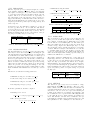
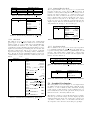
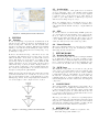
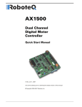
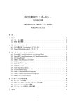
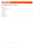
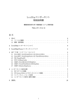
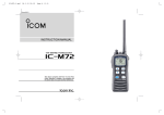
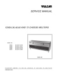
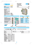
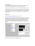
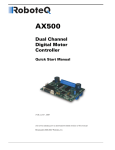
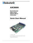
Autonomous Golf Cart Navigation Using ROS∗
David Allender
Justin Kuehn
Computer Engineering
Cal Poly, San Luis Obispo
Computer Engineering
Cal Poly, San Luis Obispo
[email protected]
[email protected]
Adam Miller
Brett Wellman
Jason Young
Computer Engieering
Cal Poly, San Luis Obispo
Computer Engineering
Cal Poly, San Luis Obispo
Computer Engieering
Cal Poly, San Luis Obispo
[email protected]
[email protected]
[email protected]
ABSTRACT
This paper describes how the usage of the Robotic Operating System facilitates the creation of an autonomous vehicle
from a standard golf cart. Robotic Operating System’s large
and powerful feature set allows for easy organization and
communication between the many different system-critical
components necessary to create an autonomous golf cart. In
this document, the background, rational, and node (or module) information of the Robot Operating System implementation will be explained in detail. The testing methodologies
used in completing the autonomous golf cart transformation
will be explained as well.
Keywords
autonomous navigation, ROS, golf cart, robot, remote control, robot operating system, robotic vehical navigation
1.
INTRODUCTION
Focusing the golf cart’s operations around one central control system, such as the Robot Operating System[?], or ROS,
has clear advantages over custom or home-brew solutions.
Like other operating systems, ROS provides numerous services and tools that both users and developers alike can
benefit from. Services such as hardware abstraction, lowlevel device control, and inter-process communication make
the usage of ROS in the redesign of the autonomous golf
cart extremely useful and worthwhile. These same services,
tools, and libraries make obtaining, writing, and using code
a much easier task. This is also an important benefit to future Capstone groups as the transition between groups will
be much more seamless and efficient.
The nodal-based system used in the golf cart will be explained in further detail in the sections below. This nodal
system allows programmers to use a level of modularity that
∗For Cal Poly CPE 450, Winter 2011
is not otherwise possible with other configurations or operating systems One of the many keen benefits this level of modularity allows for is the ability to completely detach separate
parts of the system. Those detached parts can then be further developed and unit tested to ensure each is functioning
correctly and independently of one another.
2.
BACKGROUND
The original software and hardware stacks found on the cart
are inherited from previous Cal Poly Capstone groups. Such
inheritance naturally brings both existing work to leverage
and existing limitations to design around. One of the biggest
shortcomings of the previous implementation is the custom
software stack that imposes both hardware restrictions and
can not readily leverage existing open source software to
add new functionality. The previous Java based software
stack is monolithic in design which couples the stack to the
specific hardware the stack is designed for and requires all
functionality handled in the stack to exist within a single
binary blob. To demonstrate the difficulty in adding new
functionality consider adding SICK Laser[?] based obstacle
detection.
3.
RELATED WORK
ROS is not the first, nor the only software abstraction layer
for use in robotics. There are, however, many features that
make ROS unique to these alternatives.
3.1
Player
Player is a network server for robot control. It offers a clean
and simple interface to robotic sensors and actuators over
an IP network. A player server is a software abstraction for
a robotic platform. A player client communicates with the
server over TCP sockets in order to read sensor data, command actuators, or perform on-the-fly configurations. Since
all of the source code is free and open source, it enjoys support for a wide number of existing platforms and hardware.
Because of the network communication structure, a player
client can be language and platform independent. Client
side utilities exist for C++, Tcl, Java, and Python. Part
of the Player suite includes Stage which provides a 2D simulation environment that can integrate seamlessly into the
server/client model.
3.2
MRDS
Microsoft Robotics Developer Studio (MRDS) is a proprietary software environment to facilitate robotic control and
simulation. It consists of an IDE like environment that utilizes visual programming and a 3D simulator. The Visual
Programming Language (VPL) allows creation of services
and activities that are represented by blocks with inputs
and outputs. The blocks can then be visually linked together to form an entire robotic system. The 3D simulator
employs realistic physics to simulate the behavior of your
system in a customizable virtual world. MRDS has built-in
support for a variety of existing robotic platforms including
the humanoid robot Noa, the iRobot Create, and the Lego
Mindstorm.
4. THEORY
4.1 ROS
ROS, or Robot Operating System, is an open source framework designed to provide an abstraction layer to complex
robotic hardware and software configurations. ROS is multilingual in that it supports several programming languages
including C++, Python, Octave, LISP, and more recently,
Java. It has been used in many robotic applications such as
Willow Garage’s Personal Robots Program and Stanford’s
STAIR project.
At its core, ROS provides a framework to segregate processes, also referred to as nodes, and provides the means to
communicate between these nodes. A full robotic system
contains many nodes functioning together. A Node can be
anything from a sensor publishing data, a localization algorithm, or a data logger. Each Node is designed to perform a
particular function with larger algorithms and functionality
realized through the interactions between many nodes.
control braking and toggling between forward/reverse is in
place but currently the actuator controlling the brake motor is burned out and there wasn’t enough time to integrate
forward/reverse toggling.
ROS nodes provide an ideal means of software control as
each independent mechanical control system has a dedicated ROS Node whose sole functionality is to translate
commands into mechanical actions. For the golf cart, this is
achieved through the roboteq ax1500 Node and pmad Node.
The roboteq ax1500 Node sends commands to control the
Roboteq AX1500 board [?] which steers the cart. The
PMAD Node sends commands to the Arduino which controls the AllTrax motor controller which drives the cart. See
[5.a] and [5.b.i] for further details.
4.3
Encoder
The wheel encoder is a subset of localization. Magnets are
placed on the inside of the wheel and then programmed to
determine the angular position or motion of the shaft or
axle. The output of the magnetic rotary encoder provides
information about the motion of the wheel which is typically
further processed in the localization node into information
such as speed, distance, RPM and position.
Using a set of magnets placed on the inside of the wheel and
the Arduino microcontroller, the number of ticks is able to
be counted and used in our particle filter.
4.4
Localization
The following is a list of ROS terminology that will be used
throughout the rest of the paper:
• Node - An executable unit which communicates with
other nodes through message passing
• Message - Unit of data exchanged between nodes
• Topic - Communication channel between two or more
nodes
• Publisher - Node pushing data into a Topic
Figure 1: The two main steps in a particle filter used
for localization. The Propagation step shows the
particles are increasingly spread by the odometry
error. The correction step shows how re-sampling
the particle swarm using the GPS data effectively
reduces the error from odometry
• Receiver - Node receiving data from a Topic
• Service - Remote procedure call in which Node A requests, Node B performs some action, and Node B
returns the result to Node A
4.2
Drive-By-Wire
Drive-By-Wire functionality consists of controlling a vehicle
through electrical controls rather than the mechanical controls native to the vehicle. In the case of the golf cart, the
mechanical controls are steering, acceleration, braking, and
toggling forward/reverse. Each of these systems must be
mapped to a corresponding electronic control mechanism to
provide complete control from outside the cart itself. The
AViD golf cart implements complete controls for steering
and forward acceleration. The infrastructure is in place to
The localization component is responsible for measuring the
changing position of the golf cart while in motion. Knowing
the position with a high degree of precision is necessary in
order to carefully execute maneuvers and avoid driving off
the road or hitting obstacles.
The golf cart is equipped with several sensors to help measure position: A GPS unit, a digital compass, and a wheel
encoder that measure the rotation of the wheel.
While the GPS sensor is useful in giving general position
information, it is rather poor for determining small distance
changes and has an error radius of about three meters. On
the Cal Poly campus, three meters can be the difference of
being on the road or in the side of a building.
In order to minimize the system error, multiple sensors’
data is fused using a particle filter. A particle filter, rather
than modeling just the best guess, has hundreds of possible
states, each with their own position guess. With each iteration, each particle is moved according to odometry data
plus added Gaussian noise sufficient to cover the expected
range of error in odometry data.
encoder attached to the steering column feeds back into the
AX1500 which is used to determine and reach distinct position points.
To obtain odometry data, the number of encoder ticks is
translated into distance by applying the following formula:
DistanceT ravelled =
EncoderT icks ∗ W heelCircumf erence / T icksP erRevolution
Then using a digital compass the Cartesian X and Y position can be calculated:
Figure 2: The steering control mechanisim setup
X P osition = DistanceT ravelled ∗ Cos(CompassHeading)
Y P osition = DistanceT ravelled ∗ Sin(CompassHeading)
Once the particles have been propagated using odometry,
some of the error is corrected using the GPS. Particles are
randomly sampled from the swarm with a higher weight
given to particles closer to the GPS position. The result
is a set of particles that tends to gravitate near the GPS
location while still obeying the odometry model and thus
providing a much more accurate position estimate than any
individual sensor.
5.
APPLICATION
The following section covers both hardware and software
implementation details in the AViD golf cart.
5.1
5.2
ROS Implementation
The software design follows the ROS pattern of many special purpose and independent nodes communicating through
message passing. As can be seen in Figure 3, the golfcart encoder and golfcart localization nodes receive input
from the sensors mounted on the golf cart. While not implemented, the resulting localization would be passed to a golfcart nav node which would be responsible for path planning
and navigation. The golfcart nav Node would then send
speed and steering values to the golfcart pilot node that then
communicates with the roboteq ax1500 and pmad nodes to
enact the actual changes on the golf cart.
Hardware
The core design behind the electronic controls remains similar to if not the same as when the golf cart was received. The
key differences lie in better cable management and board
placement combined with replacing the original PolyBot board
[PolyBot(2008)] used to control the cart acceleration with an
Arduino[Arduino(2010)].
5.1.1
Rewiring
Rewiring is a large aspect in re-building this golf cart. In
the beginning of the two quarter project, all of the internal
electronic components of the cart were completely tangled
and incomprehensible. It was definitely an eyesore for any
group that would work on this. One of the higher priorities
for this project was to get everything re-wired so any future
group can figure out what exactly is going on, as well as
what wires control what mechanisms. This will also prevent
frying the boards, which was fairly prevalent in the past.
Even within these two quarters, one Roboteq board, and
one Arduino board got fried by sending a 36V voltage into
a 5V input pin.
5.1.2
Steering
The steering column is driven by a DC motor controlled by
the Roboteq AX1500 motor controller board AX1500. The
board is configured to operate over RS232 in closed loop
position mode. To steer the cart, a desired position command is sent via RS232 to the AX1500 and the AX1500
powers the DC motor to reach the given position. A linear
Figure 3: ROS Implementation Flowchart Overview
5.2.1
Roboteq Node
• Maximum steering in radians
The Roboteq Node (roboteq ax1500 ) is designed to communicate with the AX1500 over RS232. The node is currently
only capable of setting speed or position values for Channel
1 or 2 in the forward direction as that is all the golf cart
requires. The node does however have no dependency on
any other feature of the golf cart and could be extended to
support the full range of AX1500 features. The current design follows the ROS Service model where the node receives
a request, performs an operation (set steering position), and
sends a response.
As stated in 5.1.2, the AX1500 is configured to operate in
closed-loop position mode. As a result, the data that is
received by the Roboteq Node and forwarded to the AX1500
is a steering position value in the range of [0-255]. Due to
limitations with the linear encoder, only a subset of the [0255] range is actually used (see section ??).
Service Request
channel forwardRequest
Data
uint8
uint8
• Minimum steering in radians
min rad = (cen enc − min enc) ∗ rad per tic
Message
geometry msgs/Twist
Golf Cart Pilot Node
The Golf Cart Pilot Node (golfcart pilot) acts as the translation layer between the nodes directly controlling the golf
cart and the higher level path planning nodes. and the GUI
node The Pilot node takes either absolute or relative speed
and steering values and sends any necessary commands to
the Roboteq and pmad nodes. An absolute command sets
the speed and steering to the values provided in the command. A relative command treats the speed and steering
values given as deltas from the current speed and steering
values. To prevent over steering and damage to the cart
the Pilot node clamps any steering command with a configurable minimum and maximum encoder value (see section
??).
Publisher Node
gui bridge
Table 2: Information golfcart pilot subscribes to
Service Request
channel forward
pmad switch control
Service Provider
roboteq ax1500
pmad service
Table 3: Service calls made by golfcart pilot
5.2.3
channel
value
Table 1: Information published by roboteq ax1500
5.2.2
max rad = (max enc − cen enc) ∗ rad per tic
Arduino Node
The acceleration for the golf cart is tested using the Arduino pmad node that was acquired from a ROS project
page. Instead of sending either a digital high or low, it has
been modified to send a PWM pulse out of the PIN3 port.
The reason PIN3 was chosen was because it gets the most
accurate voltage output. If a different pin, say 5 or 6 was
chosen, then the voltage outputted would not be as accurate
or stable. This is necessary for the Alltrax motor controller
to determine what speed the cart should be going at. The
pmad node sends packets to the Arduino itself and the Arduino checks the input, while sending a specified duty cycle
PWM to the Alltrax motor controller.
The arduino outputs at 500Hz and up to 5 volts. The pmad
input ranges from 0 to 255, but the lower bound threshold
for the cart to move is 150, which is only a 58% duty cycle.
Any lower duty cycle and the cart will not move. Despite
this disadvantage, the cart was still able to have a large range
of speed levels and allowing the programmers to achieve a
higher granularity rate. There will be a noticable change in
speed every after a positive or negative change of 5 percent
in duty cycle.
The Pilot node takes the following parameters:
Service Request
channel forward
• Minimum steering encoder value (min enc)
Data
uint8
uint8
channel
value
Table 4: Service Calls Made by pmad
• Centered steering encoder value (cen enc)
• Maximum steering encoder value (max enc)
• Steering range in degree (range)
From these paramaters, the Pilot computes:
• Radians per encoder tic
rad per tic = rad(range)/(max enc − min enc)
• Encoder tics per radian
tic per rad = 1/rad per tic
5.2.4
GUI Node
The GUI Node (gui bridge) acts as a medium to bridge
ROS with the Graphical User Interface. The node establishes a TCP connection with the GUI from which it can
send status information and receive system commands. It
subscribes to the encoder node for speed and heading information, the GPS node for latitude and longitude, and
the localization node for position data. Offloading this data
to the GUI allows for a much aesthetic presentation for
users. The GUI also can issue drive commands to the systems which are translated into the Twist message type and
then published for the consumption of the Pilot node.
Message
golfcart encoder
gps common/NavSatFix
geometry msg/Pose2D
Publisher Node
golfcart encoder
gpsd client
golfcart localization
Table 5: Service calls made by gui bridge
Message
geometry msgs/Twist
Data
Vector3 linear
float64
float64
float64
Vector3 angular
float64
float64
float64
z
x
y
z
5.2.6
Message
golfcart encoder
x
y
Table 6: Information published by gui bridge
5.2.5
GPS Node
Data
uint32
ticks
float32
speed
float32
heading
Header header
uint32
seq
time
stamp
string
frame id
Table 8: Information published by golfcart encoder
The GPS Node (gpsd client) leverages the existing ROS
gpsd wrapper node. Gpsd is a Linux service daemon that
interfaces with one or more GPS devices and simplifies the
data and makes it available on a common TCP port. This
encapsulation greatly simplifies the implementing by relieving the burden of having to manually parse the relevant data
through a serial stream. The node is capable of publishing several message types containing a variety of GPS data.
Here only the most basic NavSatFix message is used as it
contains all the necessary data items consumed by the localization
node.
Message
gps common/NavSatFix
Compass/Encoder Node
The Compass and Encoder node (golfcart encoder ) was built
from the ground up to service the needs of the system. It
publishes odometry and heading information using a custom
message type that is designed to be consumed by the localization node. Encoder ticks are intercepted by an Arduino
micro-controller that reports the current tick count on a serial port that is read by the node. Heading is also obtained
by the encoder node by parsing the serial stream from the
digital compass. The node then calculates the current speed
and publishes the message to the relevant topic.
Data
int8
status
uint16
service
float64
latitude
float64
longitude
float64
altitude
float64[9] position covariance
uint8
position covariance type
Header header
uint32
seq
time
stamp
string
frame id
NavSatStatus status
int8
STATUS NO FIX=-1
int8
STATUS FIX=0
int8
STATUS SBAS FIX=1
int8
STATUS GBAS FIX=2
uint16
SERVICE GPS=1
uint16
SERVICE GLONASS=2
uint16
SERVICE COMPASS=4
uint16
SERVICE GALILEO=8
Table 7: Information published by gpsd client
5.2.7
Localization Node
The Localization Node (golfcart localization)is responsible
for continually running the particle filter algorithm and to
report the current position estimate by publishing the Pose2D
message. The particle filter consumes the odometry data
provided by the encoder node and the current longitude and
latitude from the GPS node.
Message
golfcart encoder
gps common/NavSatFix
Publisher Node
golfcart encoder
gpsd client
Table 9: Information golfcart localization subscribes
to
Message
geometry msgs/Pose2D
Publisher Node
float64
x
float64
y
float64 theta
Table 10: Information golfcart localization publishes
5.3
Graphical User Interface
The GUI, pictured below in Figure ??, was implemented
modularly in Python and Qt using PyQt. This allows the
interface to be run on Windows, Mac, and Linux, allowing
a wide variety of platform usage. It uses a TCP-based connection that allows control of the golf cart from any location
that has network connectivity with the cart.
The interface consists of controls allowing the user to manipulate the speed and wheel angle, and also displays updated
status information from the cart, such as the compass readout, GPS coordinates, and so on. In addition, the interface
also maps the cart’s current location using Google Maps.
6.2
Acceleration
Using the pmad interface, a fine grained set of acceleration
speeds is achievable. Due to the simulated analog signal
by PWM, a minimum duty cycle of about 58% is required
to make the cart go at its slowest speed. After that, it is
possible to get a large number of different speed presets,
with noticeable change in speed every 5
There were multiple ways to test this sub-section of driveby-wire. One primary way is to send the node ROS service
calls, which tells the Arduino directly to output PWM out
of PIN3.
6.3
Figure 4: Multi-platform GUI interface
6. TESTING
6.1 Steering
To test steering range, responsiveness, and limits the front
wheels were raised off the ground for both manual and controlled steering tests. The first test run determined the
amount of steering range available. This involved manually
turning to each extreme and measuring the angle between.
The result from this testing showed a steering range of approximately 66 degrees.
From here the functional range of the linear encoder was
determined. The AX1500 expects a voltage range of [0-5]V
which is internally converted into a position value between
[0-255]. The linear encoder is capable of operating over the
[0-5]V range but the steering range doesn’t utilize the full
length of the linear encoder. As a result, only the position
values in the range of [42-98] are usable. Trying to turn to a
position outside of this range could potentially damage the
motor as the steering will turn to one extreme as the motor
attempts to turn past the physical limit.
Finally, the last tests run measured how linear the steering
position measurements were. Ideally the encoder tics computed by the AX1500 would be evenly distributed over the
turning range. In fact, the steering is right biased with more
encoder tics right of center compared to left of center.
GPS
To test the GPS Node’s functionality, NMEA packets are
decoded directly from the hardware device and read into
the node. The node then passes the raw NMEA data to
a function and makes sure that the data being received is
correct. Finally, the data is run through a particle filter to
ensure the data retrieved is as accurate as possible.
6.4
Linear Encoder
The Celesco SP2 linear string encoder is tested by reading in
the values from the Roboteq board, and having it calculate
what angle the wheel is turned to.
7. FUTURE WORK
7.1 Braking Mechanism
Due to the sheer weight of the cart, the breaking mechanism
is one thing that should be looked into for future groups,
although it is not necessarily the highest priority item. If the
motor controller suddenly stopped, then assuming the cart
is on a level road, it would come to a stop instantaneously.
7.2
SICK Laser
The SICK laser range finder once mounted to the golf cart
can be used to detect impending obstacles so that the vehicle can take appropriate action to avoid a collision. Thanks
to ROS and its support of the SICK toolbox, integration of
the laser into our software is already completed. The only
remaining tasks are to build a a suitable mounting mechanism and implement avoidance features into the navigation
component.
8.
CONCLUSION
After much planning, implementation, and testing, all of
the carts different, yet equally important ROS nodes come
together and work in sync. It is this complete system, with
all nodes working together as a unit, that allows the cart
to be driven around Cal Poly’s campus without the aid of a
manual driver in the drivers seat.
The true power and scope of the Robot Operating System
cannot be understated. It’s implementation and subsequent
usage allows for usefulness far beyond home-brew solutions
and makes the daunting task of turning a regular golf cart
into an autonomous vehicle much more achievable.
Figure 5: Steering position measurements
9.
REFERENCES
[Arduino(2010)] Arduino. Arduino development board,
2010. URL http://www.arduino.cc/.
[PolyBot(2008)] CalPoly PolyBot. Polybot development
board, September 2008. URL
http://users.csc.calpoly.edu/~
jseng/PolyBot_Board.html.
[Roboteq(2009)] Roboteq. AX1500 User’s Manual, 2009.
URL
http://www.roboteq.com/files/manuals/ax1500man19b060107.pdf.
[ROS(2011)] ROS. Robot operatin system, creative
commons attribution 3.0, February 2011. URL
http://www.ros.org.
[SICK(2011)] SICK. The sick lidar matlab/c++ toolbox,
2011. URL http://sicktoolbox.sourceforge.net/.