1
XL-2G
Hookup and Installation Instructions
FIRE BURGLARY INSTRUMENTS, INC.
Subsidiary of Pittway Corp.
149 Eileen Way, Syosset, NY 11791
N9476 7/95
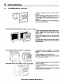
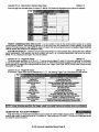
THANK YOU for your purchase of the FBII
XL-2 GOLD.
The purpose of the manual is to give you a brief overview of the XL-2G control panel, and provide instructions
for installing a basic system. FBI I is always available to setve YOU. Our SALES and TECHNICAL SUPPORT
staff are available to assist you in any way possible.
SALES , REPAIRS
OR
TECHNICAL
S ERVICE ,
CALL TOLL FREE :
(800)
645 -5430
FOR
Before you call Technical Service, be sure you:
•l Check the wiring diagram and verify your connections.
•J Check all fuses.
El Assure that the transformer
and backup batte~
voltages are supplying the proper voltage levels.
El Verify your programming information.
El Read this manual thoroughly.
IZIConsult the Troubleshooting
Section of this Manual.
El Note the roper model number of this product, and the version level (if known) along with any
documen Patlon that came with the product.
•I Have your company
name and telephone
number ready.
This information will allow us to service you more quickly and effectively. Please, remember
while waiting on the telephone; your call will be answered as soon as possible.
to BE PATlENT
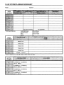
FOR YOUR CONVENIENCE,
a System Planning Worksheet and a Programming Worksheet
the back of this manual. These can be removed to help you record account information.
XL-2G Hookup&
Installation
Manual Page 3
is included at
TABLE OF CONTENTS
INTRODUCTION . . . . . . . . . . . . . . . . . . ...7
SYSTEM WIRING AND HOOKUP . . . . ...8
Wiring Diagram . . . . . . . . . . . . . . ..8
Terminal Connections . . . . . . . . . . . . ...9
AuX.DeviceCurrent Worksheet . . . . . .13
WiringInfo.forZones &Keypads . . . ..l 3
PCBOARDINSTALLATION . . . . . . . . . . . ...14
MountingthePCBoard . . . . . . . . . . . ..14
KEYPAD MOUNTING . . . . . . . . . . . . ...15
XL4600RM Keypad . . . . . . . . . . . . . ..15
XL4600SM Keypad . . . . . . . . . . . . . . ..16
6805 &6615 Keypads . . . . . . . . . . . . ..17
KEYPAD LAYOUT . . . . . . . . . . . . . . . . . . . ...18
Keypad Sounder . . . . . . . . . . . . . . . . ...20
SYSTEM OPERATIONS . . . . . . . . . . . . . . . ...20
PowerUp/System Reset . . . . . . . . . . . ..20
Arming. . . . . . . . . . . . . . . . . . . . . . . ...20
StayArming . . . . . . . . . . . . . . . . . . . ...21
InstantArming . . . . . . . . . . . . . . . . . ...21
Stay-InstantArming . . . . . . . . . . . . . ...21
Disarming . . . . . . . . . . . . . . . . . . . . ...21
Reset . . . . . . . . . . . . . . . . . . . . . . . . . ...21
Bypass . . . . . . . . . . . . . . . . . . . . . . . ...21
Quick Bypass . . . . . . . . . . . . . . . . . . ...22
Auto-Unbypass . . . . . . . . . . . . . . . . ...22
Manual Unbypass . . . . . . . . . . . . . . ...22
UserCode Programming . . . . . . . . . ...22
UserDeletion . . . . . . . . . . . . . . . . . . ...23
KeypadEmergency Conditions . . . . . .23
QUICK COMMAND MODES . . . . . . . . . . . ...24
QuickArming . . . . . . . . . . . . . . . . . . . .24
Quick Force Arming ..,..., . . . . . . ...24
Toggle Chime . . . . . . . . . . . . . . . . . ...24
On-line Download . . . . . . . . . . . . . . ...24
INSTALLERMODES . . . . . . . . . . . . ., . . . ...25
InstallerKeypadProgramming . . . . ...25
System Default . . . . . . . . . . . . . . . . . ...25
UserCode Default . . . . . . . . . . . . . . . ..25
System LogView . . . . . . . . . . . . . . . ...25
UnattendedDownload . . . . . . . . . . . . ..25
On-line Download . . . . . . . . . . . . . . ...26
SYSTEM PROGRAMMING . . . . . . . . . . . . ...26
PROGRAMMINGQUESTIONS . . . . . . . . . ...27
01 PrimaryTelephone Number . . . . ...27
02 SecondaryTelephone Number . . ...27
03 Callback TelephoneNumber . . . . . 27
04 Dialer Options . . . . . . . . . . . . ...27
05 Keypad Conditions . . . . . . . . . . . ...28
06 System Timeouts . . . . . . . . . . . ...31
07 Misc. System Options . . . . . . . . ..32
08 AccountNumber l . . . . . . . . . . . ...33
XL-2G Hookup&
09 AccountNumber2 . . . . . . . . . . . ...34
ZONEPROGRAMMING . . . . . . . . . . . . . . . ...34
10ZoneNumber l . . . . . . . . . . . . . . ...36
llZoneNumber2
. . . . . . . . . . . . . . . ..36
12 ZoneNumber3 . . . . . . . . . . . . . . ...36
13 ZoneNumber4 . . . . . . . . . . . . . . ...36
14ZoneNumber5 . . . . . . . . . . . . . . . ..36
15 ZoneNumber6 . . . . . . . . . . . . . . ..37
16Ambush/ACLoss . . . . . . . . . . . . ...37
17Panic/LowBattery . . . . . . . . . . . . ..37
180pen/Close/CSTest . . . . . . . . . . ...37
19 Bypass/Restore/Trouble/Cancel . .37
20KeypadFirelKeypad Auxiliary . . ...38
21 CSTestOffset . . . . . . . . . . . . . . ...38
00 InstallerCode . . . . . . . . . . . . . . ...38
DATAENTRYVIA LED&LCDKEYPADS .39
Howto EnterProgramming Mode . ...39
WhatYouSeeOnthe LEDKeypad.. .3 9
WhatYouSeeOnthe LCDKeypad...4O
Howto EnterData . . . . . . . . . . . . . . ...40
ExitSystemProgram Mode . . . . . . . ...4 1
SummaryofSystem Programming . . . . 41
ZoneDescriptorProgramming . . . . ...42
SYSTEM DEFAULTS...............,..
..43
SUMMARY OF KEYPAD FUNCTIONS. . ..44
User Functions . . . . . . . . . . . . . . . . . . .44
Installer Modes . . . . . . . . . . . . . . . . . . . 44
APPENDIX A- CSREP. FORMATS . . . . . ...45
Standard (3Xlor4Xl) . . . . . . . . . . ...45
Extended (3Xlor4Xl) . . . . . . . . . . ...46
Part. Ext. (3Xlor4Xl) . . . . . . . . . . ...46
3X20r4X2 . . . . . . . . . . . . . . . . . . . ...46
APPENDIX B - TROUBLESHOOTING . . . . ..47
SYSTEM PLANNING WORKSHEET . . . . ...48
Zone Information . . . . . . . . . . . . . . . . . .48
User Codes . . . . . . . . . . . . . . . . . . . . . . .48
Keypads . . . . . . . . . . . . . . . . . . . . . . ...48
SYSTEMPROG RAMMING WORKSHEET. ..49
WARNING LIMITATIONS STATEMENT . ..50
WARRANTY . . . . . . . . . . . . . . . . . . . . . . . ... .51
FCC STATEMENT . . . . . . . . . . . . . . . . . . . ...51
Installation
Manual Page 4
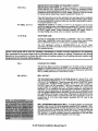
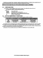
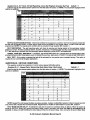
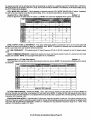
The XL-2G is an enhanced version of the XL-2 control panel. Some new features have been added and others
have been modified. The following is a quick comparison.
~ .
Unattended Download (Installer Mode 3)
.
Standard Download Only
On-line Download (Installer Mode 4 or # 4)
Standard Download Only
2 Entry Timers (program quest. #06)
1 Entry Timer
Swinger Shutdown - Bell and Dialer Lockout
(program quest. #04)
Bell Lockout
Multiple digits required
$%’g!%tl!i-l%!?%%%y)
- ‘ ‘igit ‘“ty
- not cleared
2 to 12 Alarms Event Histo
by user code (Installer Mode ‘? )
6 Alarms Event Memory (cleared by user code)
Smoke Power or Pro rammable Trig er #1
Output/Terminal P1-1+ (program ques.P #07)
Smoke Power Only
Programmable
NONE
Trigger #2 Output
Terminal P1-T2 (program quest. #07)
CS Test Timer -1 Da 7 Day 27 Day, 60 Day
or 90 Day Reset b{ ~~ Test drily
CS Test Timer 1 Day Only Reset by
Any Event
CS Test Timer Offset
NONE
(program quest. #O )
(program quest. #21)
CS Test Key ad Rin back Programmable
as Silent or 1“?
udlble program quest. #05)
CS Test Keypad Ringback always Audible
1 Hour CS Test (program quest. #05)
NONE
Cancel Code (program quest. #19)
NONE; Restore Code Only
Bell to Verify Cancel (program quest. #04)
NONE
End User Chime ON/OFF Toggle (#6)
NONE
European
Ring Detect (program quest. #05)
Exit Error Warning
NONE
NONE
(always enabled)
Restore Follows Bell or Loop (program quest. #05)
Restore Follows Bell Only
Bypass In Stay - Any Controlled Zone can be
Interior Zones Only Bypassed in Stay Mode
S stem Stabilization on Power Up -to Eliminate
d otlon Detector False Alarms
NONE
Fast Loop Response
NONE
Bypassed in Stay Mode (program quests. #1O-15)
10 msec) Option by Zone
(progam quests. #l O-l k )
AC (50/60 HZ) Based System Real Time Clock
(program quest. #05)
Bell Supervision
- New NFPA 72 Requirement
Software
Based System Timing
NONE
(program quest. #15)
Stay Mode 40 Sec. Dialer Delay w/BeIl & Keypad
Sounder Warnin
for All Zones
(program quest. d 5)
LED Displa
& Keypad Sounder on Entry Zone
(always ena%led)
XL-2G Hookup&
Installation
Stay Mode Ent. Delay w/Key ad Sounder
Warning for EXIv Entry Zones 8 nly
Keypad Sounder Only
Manual Page 5
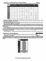
XL . 2G FEATURE CHANGFS
XL . 2 SIMl&AR FEATU/WS
System Wide Restore Code Enable
(program quest. #19)
Restore Codes selectable by each zone
System Wide 15 Sec. Dialer Delay for
controlled zones (program quest. #07)
15 Sec. Dialer Delay selectable by each zone
Instant Armin
Pro rammable
(program ques??
. #05
Instant Arming Always Enabled
User 5- Arm Only User capability
removed
User 5- Arm Only User optional
Keypad Fire Always Enabled; CS Report
Programmable (program quest. #20)
Keypad Fire Programmable
Keypad Auxiliary Always Enabled; CS Report
Programmable (program quest. #20)
Keypad Auxiliary Programmable
Ring Count O tions: 0,2,4,6,8,
(program ques.1’ #07)
Ring Count Options: 0-15
10, 12, 14
Quick Commands (Quick Arm, Quick Forced Arm
& Quick Bypass enabled together
(program quest. J 05)
Reset (* key) always enabled for Fire Alarms Only
XL-2G Hookup&
Installation
Quick Arm & Quick Forced Arm/Quick
Bypass enabled separately
Reset * key) programmable for Both Burglar
& Fire k Iarms
Manual Page 6
1.
INTRODUCTION
The XL-2G Security System is a state of the art microprocessor-based controlkommunicator. Programming can be
performed through any of the compatible keypads or the system can be uploaded and downloaded remotely usin the EZ-Mate
PC Downloader Software. In addition, remote control actions (arming, disarming, bypassing, etc.) can be pe r?ormed by the
software. Programming options are stored in non-volatile reprogrammable EEPROM memory and that information which has
been programmed will not be lost in the event of a complete loss of power. Other features of the XL-2G include:
●
●
●
●
●
●
●
●
●
●
●
●
●
●
●
●
●
●
●
●
●
●
●
●
●
●
7 Zones (6 fully programmable plus a wired panic zone or keyswitch zone)
4 types of compatible keypads (LCD& LED, fdur wire devices with up to four per system)
6 user codes with capability for ambush code
4 selectable keypad emergency conditions
Fast Loop Response (1Omsec) selectable by zone
NFPA 72 Bell Supervision
CS Test Timer Offset
English readout keypads available with programmable 12 character zone descriptors
Upload/Download with remote commands with answering machine bypass
Unattended and On-line Downloading
Default Lockout option to prevent hostile account takeovers
Quick arming, Quick Forced Arming and Quick Bypass option
Indications on keypad for AC loss, Low Battery and Communication Failure
Central Station reportin for Alarms Troubles, Restores, Bypasses, Openings, Closings, Ambush, Panic,
Keypad Fire, Keypad h?edcal, 24H~. Test, Cancels, AC loss, and Low Battery
Can be programmed as a Local System (No C.S. Reporting)
4 wire smoke detectors with Fire Verification logic plus smoke power reset
2 entry and 1 exit time delays
Swinger Shutdown capability
Exit Error Warning
European Ring Detect
Event Log will store 2-12 alarm events: all zones that alarmed will be displayed for each event (ARMING
CYCLE)
End user chime ON/OFF toggle capability
2 pro rammable trigger outputs for various functions (including armed/ready indication and glass break
dete 8 or reset)
Input Power 12VAC 20VA 12VDC, 4-7 AH
Output Power 11.5-13. lVDC, 500mA
Bell Output Power 10- 15.5VDC, 1A
XL-2G Hookup&
Installation
Manual Page 7
2.
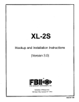
SYSTEM WIRING AND HOOKUP
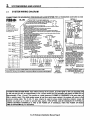
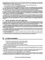
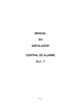
2.1.
SYSTEM WIRING DIAGRAM
CONNECTIONS
mm}
FIRE BURGLARY IN51RUMEN15,
FOR HOUSEHOLD
XL-2G
Topreventriskfrom
shock,
energize
de-
the system
control
unit and disconnect
the telephone
servicing
lines before
this unit.
1
ZONE1
2.2K
ZONE2
2
2,2K
3
2.2K
ZONE4
2.2K
,3. Prcgremmab4e output -r.
8ati10isto
knomwtim3f~ttimtie
cOfrfml un!l with no barriers in between.
If used for smoke
detector cower mru?tsan Detail A. Consuil inStsffs&programming
rnfennsfkm.
Connwt XL2GTC trigger csbfe.
sane:
4 Am
THIS FUSE N& T
REPLACEABLE uj~~
(S8.9 nole 9)
[ TERMINALS
(+)
(-)
9
—
-1
10
1
I II 11 h
7P2
JP1
cc
RED
BIACK
..m
lMODEL1240j ~
.
8
—
I
DETAIL A
—
osec.
5
IH
ZONE6
ZONE
flsec.,sxiioefsys
6
ZONE5 =79.
I
VShh3S,
remove
onrmtonofVS-2SS
SirenDiver &wstwd
positive(+)
unre#awrfoufpvt(10-15.5VOCJ.
12 - ThaPANIC or K SWfTCH connected to twminela
-.
ZONE3
TO
fSiOSCf
factory
dafetrff
(PER UL STANDARDS UL985 AND UL1023)
1- Connect to a gmwvkd nmfel cdd water @e (lSgs at 15 R).
2- ToM AUX. oewer avsilebfs fincludtrmhewed oowert is KIOM mex Used for cennecfii of devices
retedh&nil.5fo13.l
w:
‘“
3- System must be tested on a weekivbasis.Fw inlorrnatbn, refer fo retemcee.
4 -Do net connect the trsnsfermer to a svdtch conboffed receptssle.
S - Insfslfstien of equipment snd wiring methods m required to bs in s.ccordsnca with the Netii
Elecbfsel sode end ANSW4FPA No. 74. More information may M obteimd from tke NFPA, Oattqma$ch
Pedt, Ouiiy, MA 02269.
6- aeftery sapecify for Emergency .%ndby is a minimum of 4 hw~. fJwJw cO~~$
~~ beffery
will Iket 3 yeers. Use only exesttepiacements.
7- Meximum of 4 keypsds, Availsbb keypsds inslude
F2
FI
xL-4600RM, XL-46CCSM, tW15, 600S.
Sell Power
Aux. Pwtmr
S- Mni4ed eneqy csble must h d.
3 Amw
1
Amp
9- f4cm-rePIsc@ab4e
fuse. Return unit to msnfectumr if
blown. CCInot solder fuse in fefd.
10. MdMISII fortJLimfaflstiOIM
&lby
Oday:
Do
.
-
DEFAULTRES~:
ALARM SYSTEM
allpowerfromsystem(ACandDC).Next,shortJP1
toJP2 Withshortstillintact,reapplypower(ACthenDC),wait
5 seconds,thenremoveshortwtih power still applied.
lNC
WARNING
electric
FIRE/BURGLAR
NIC
-.
CN-I
“7!
I A GROUN
,<Ga ““,a ,,
I
t-
4
3
5
E=tH
I
PANIC
I
]
10
8
. .
------------L ------● UL INSTALLATIONS REQUIRE LISTE#
END-OF-LINE DEVICE. USE RESISTOR
FROM EOL22 KIT. LOOK FOR LISTING
MARK ON ITEM.
WARNING
THIS UNIT INCLUDES AN ALARM VERIFICATION FEATURE THAT WILL RESULT IN
A DEfAY OF THE SYSTEM ALARM SfGNAL FROM THE INDICATED CIRCUITS.
TNE TOTAL DELAY (CONTROL UNIT
PLUS SMOKE D~ECTOR) SHALL NOT
EXCEED 60 SECONDS. NO OTHER lNlTlATING
DEVICES SHALL BE CONNECTED
R
TO THESECIRCUITSUNLESS
APPROVEDBYTHE LOCALAUTHORITY
HAVINGJURISDICTION.
1
CIXR&UJT
CCIIJ~LK31U~fTSMOKEDE7ECTOR
1
FCC Registration Number AE398E-69554
AL-E Ringer Equivalence O.OB
[ References: Hookup and Installation Instructions N9476 and Owner’s Manual N9475j
I
AIARMOUTPUT
11.5-13.1VDc
1Ampmax.
(7WnAmex)
,..
,,,
:_..-,,A\--.\
ir.rrUL Insunlmwrlb)
—
ml
-“
MODELDELAYSEC
—
PRODUCT COVERED UNDER
US PATENT #4,791 ,658
N9474 Rev, A 7/95
SYSTEM STABILIZATION MODE: Upon initial powerup of the system, all of the lights on the LED keypad(s~
go ON and then go OFF for approximately 2 min. 10 sees and/or the LCD keypad(s) will display STAND BY! for
approximately 2 min. 10 sees. This occurs on a total powerup (if ARMED or DISARMED in its prior state) or
after a system reset. If the total system power is lost then upon power restoral, the system will return to the
previous arming state. The 2 min. 10 sees. intewal is used to allow motion detectors (interior zones) to
stabilize on power up in order to prevent false alarms. THIS OPTION CAN BE DISABLED BY PUTTING A
JUMPER BETVVEEN TERMINALS 13 AND 12 ON POWER UP. IF DISABLED, THEN THE POWER UP RESET
TIME IS APPROXIMATELY
5 SECONDS.
XL-2G Hookup&
Installation Manual Page 8
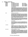
2.2.
TERMINAL CONNECTIONS
TERMINALS
‘1(+) & 2(.)
DESCRIPTION
Zone 1 (Requires 2.2K EOL resistor)
3(+)
4(+)
6(+)
7(+)
9(+)
Zone
Zone
Zone
Zone
Zone
&
&
&
&
&
2(-)
5(-)
5(-)
8(-)
8(-)
2 (Requires
3 (Requires
4 (Requires
5 (Requires
6 (Requires
2.2K
2.2K
2.2K
2.2K
2.2K
EOL resistor)
EOL resistor)
EOL resistor)
EOL resistor)
EOL resistor)
[Default
[Default
[Default
[Default
[Default
[Default
=
=
=
=
=
=
DELAY]
INTERIOR]
PERIMETER]
PERIMETER]
PERIMETER]
PERIMETER]
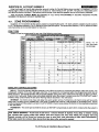
ZONE INFORMATION:
Normally closed devices may be wired in series and/or normally open devices
in parallel with the 2.2k ohm end of line resistor on all zones (Refer to the wiring
diagram). The standard loop response time is 280 ms on all zones. Each zone
can be programmed for Fast Response (10 ms) in programming (see questions
#1O-15). The factory default values for each zone is listed in the table above,
however any zone can be programmed for the following types: Delay,
Perimeter, Interior, Fire, 24 Hr. Alarm, or 24 Hr. Trouble. Further explanation of
the zone types can be found in the System Programming section of this manual.
NOTE: Loop response is defined as the minimum time required for a fault to trip
a zone.
PANIC CIRCUIT OR KEYSWITCH:
8&10
Normally Open PANIC circuit. This hardwired panic is a 24 hour zone which can
be programmed for silent or audible operation. The panic circuit will activate with
each violation, therefore a latched device is not recommended. A momenta~
device is recommended. For UL installations, the panic switch connected to
these terminals is to be located no more than 3 feet from the control unit, with
no intervening barriers (this is a supervision requirement only). If the keyswitch
option is selected (see programming question 05,10cation 2), then each
activation of the keyswitch will arm and disarm the system.
NOTE: E.O.L. resistor is not required on this zone and is not supervised. This
zone does not report restore codes. If a supervised zone with restore reporting
ability is desired, then program one of the 6 zones as a 24Hr. Alarm. If used as
a keyswitch, then triggers are available for either an arming or ready status
indication (see programming question 7, location 4).
EARTH GROUND:
11
Connect this grounding lug to a cold water pipe utilizing #18AWG wire at a
distance of no greater than 15 ft. Use a non-corrosive metal strap firmly secured
to the pipe to which the lead is electrically connected and secured. If the
premises pipes terminate in PVC, this terminal must be connected to a six(6)
foot grounding rod.
12131415
KEYPADS:
A maximum of 4 keypads, either XL4600RM, XL-4600SM, 6615, or 6805, may
be wired to these terminals. The connections are as follows; 12 (BLACK =
negative), 13 (YELLOW = data in),14 (GREEN = data out) and 15 (RED =
positive power). Each keypad draws approximately 30mA. Maximum keypad
length is 500 feet using 22 gauge wire. NOTE: In some installations, it maybe
necessaty to use shielded wire to prevent radio frequency interference.
12 (-)&15
(+)
REGULATED
POWER (11.5 - 13.lVDC):
The total regulated output power for motion detectors and other external
devices is 500mA at 11.8- 12.5V for residential applications, or 12.0- 12.5V for
commercial applications, with less than 100 mVPP ripple. The total regulated
output capacity of the XL-2G includes the power available from these terminals
(15 & 12) as well as the power used by the keypads and smoke detectors.
Therefore, to determine the total power available from these terminals subtract
the power consumed by the keypads and smoke detectors, See Auxiliary Device
Current Draw Worksheet.
XL-2G Hookup&
Installation
Manual Page 9
15(+) 16 (-)
SMOKE DETECTOR POWER OR TRIGGER #1 OUTPUT:
SMOKE DETECTOR POWER. This system will accept 9.5- 12VDC four(4) wire
smoke detectors only. Approximately 50mA of current is available at these
terminals for powering all detectors and an E.O.L. relay FBII model 620. For UL
installations see wiring diagram for hookup. NOTE: Trigger#l must be selected
for smoke detector power (see program question #07, location 3).
Pl: VBELL (+) TI (-)
17181920
These terminals adhere to the fire verification and reset logic which is explained
in the zone types section of this manual. Manual reset of smoke detector power
can be accomplished by entering a valid user code after clearing alarm memory
or using the asterisk (*) key.
TRIGGER #1 OUTPUT PI-VBELL(+) & PI-TI (-) or terminals 15 & 16 can be
used for a trigger #1 output. See programming question #07, location 3 for valid
trigger types. NOTE: In order to connect devices to the triggers use connector
XL-2GTC (trigger cable), Unless otherwise specified, the trigger output is
normally floating and actively sinks on activation (switched negative).
TELEPHONE
LINE:
Connect the model 368 cord as follows; 17 (GREEN = Telco Tip), 18(RED =
Telco Ring), 19(BROWN= Home Tip), 20(GRAY= Home Ring). Insert the plug
into an USOCRJ31X jack (or a CA31A jack for Canadian installations),
The FCC registration number is (AE398E-69554 AL-E), and the ringer
equivalence is (0.OB). The system should not be connected to party lines, or
coin operated phones.
~If this control panel will be used for uploading, downloading
or remote command applications, the telephone
line connected-to the control paneI must not be shared with a fax machine or modem. Furthermore, this device
should not be connected to a phone line which has call waiting, unless the call waiting interrupt numbers are
programmed into the panel dialing sequence.
I
21(+)
CONSTANT
DC POWER:
This terminal delivers constant unregulated 10.O-15.5VDC power for devices
requiring a constant power such as VS279. It is connected to a bell fuse (F3).
NOTE: Constant power for these devices can also be obtained by splicing the
RED (+) battery lead with an in-line fuse of 3 Amps.
22(+) & 23(-)
BELL OUTPUT:
The total output power available for sounding devices is 1 amp at 10.5 -15.5
VDC for residential applications, or 12.0 -14.4 VDC for commercial installations
(750 mA for UL installations). These terminals will deliver CONSTANT output
on BURGLARY, AUDIBLE PANIC and BELL TEST, On a FIRE condition, a
PULSED output will be generated. There are separate bell cutoff times
programmable for Burglary and Fire conditions within the programming
sequence. For UL Household Fire Warning System installations, the speaker is
required to be mounted indoors for best audibility. Also, for UL installations, use
only one speaker. NOTE: Before connecting sounding devices please consult
their specifications for proper current draw. Othetwise, the bell fuse (F3) may
be blown. An option exists to supervise the bell output terminals if zone 6 is
programmed as a fire zone (see program questions #1O-15); refer to the
following notes:
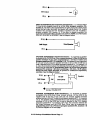
BELL SUPERVISION (Mechanical Bell ) -To meet the NFPA 72 requirement
program zone 6 as a Fire Zone (program question #15, locations 1 & 2).
The bell is then supervised for an open circuit (not a short circuit) across the
bell output terminals; the keypad will indicate that a Fire Trouble condition has
occured and Fire Trouble is reported to the CS if enabled ( program question
#19, location 3). If the bell is already ringing, the supervision will not take effect
until after bell cutoff time. See the diagram on the next page:
XL-2G Hookup&
Installation
Manual Page 10
22 (+)
●
Bell Output
23 (-)
o9
I
Bell
I
●
SIREN SUPERVISION (Self Contained Siren/Speaker ) -To meet the NFPA
72 requirement program zone 6 as a Fire Zone (program question #15,
location 1). The siren is then supervised for an open circuit (not a short circuit)
across the bell output terminals; the keypad will indicate that a Fire Trouble
condition has occured and Fire Trouble is reported to the CS if enabled (
program question #19, location 3). If the siren is already sounding, the
supervision will not take effect until after bell cutoff time. NOTE: Use FBII models
ZR-815C, ZR-815EC or ZR-830EC. See the diagram below:
22(+)
~
Od!output
23(-).
SPEAKER SUPERVISION (VS-299 Siren/Driver) - To supervise a speaker
connected to the VS-299 Siren Driver connect terminal 1 of the VS-299 to the
positive terminal of any zone programmed as a 24 Hour Trouble zone
(program questions #10 -15, locations 1 & 2). The speaker is then supervised
for an open circuit across the speaker terminals (4 & 5) of the VS-299 and a
code is reported to the CS if enabled (program question #10-15, locations 3 &
4). Also, the connection between the bell output terminals and the VS-299 Siren
Driver may be supervised by programming zone 6 as a Fire Zone (program
question #15, locations 1 &2) and connecting a I OK Ohm, 1/4 W resistor
across the bell output terminals to prevent
condition. See the diagram below.
continuous supervisory
4
2
22 (+)
a
Speaker
qfdt OutpiJt
Siren Driver
23 (-)
7
5
~
1
I
24 Hour Trouble Zone
SPEAKER SUPERVISION (679S Siren/Driver) - To supervise a speaker
connected to the 679S Siren Driver connect terminal 4 of the 679S to the
negative side of the loop of any zone (do not connect negative terminal)
programmed as a 24 Hour Trouble zone (program questions #1 0-15, locations
1 & 2). The speaker is then supervised for an open circuit across the speaker
terminals (4 & 5) of the 679S and a code is reported to the CS if enabled
(program question #10 -15, locations 3 & 4). Also, the connection between the
bell output terminals and the 679S Siren Driver may be supervised by
programming zone 6 as a Fire Zone (program question #15, locations 1 &
2). See the diagram on the next page:
XL-2G Hookup&
Installation
Manual Page 11
*
2.2K EOL
22 (+)
●—
Bell Output
23 (-)
(+)
24 Hour Trouble Zone
● (-) (00M Camat)
lor3
Speaker
~
●
TRANSFORMER
24& 25
Connect the 12 VAC 20VA transformer, utilizing 18awg wire at a distance not
120 VAC outlet.
to exceed 15 feet from the panel, to an unstitched
Do not use any other transformer since this may result in improper operation or
damage to the unit.
The AC/LOW BAT LED on the keypad will remain ON, while AC power is
present. If an AC loss occurs the AC/LOW BAT LED will turn off immediately.
If AC remains OFF for 15 minutes, the system will pulse the keypad buzzer and
transmit to the central station, if programmed. THE KEYPAD BUZZER CAN BE
SILENCED by entry of any valid user rode. When AC restores the AC/LOW
BAT LED will light immediately, and a restore code will be reported, if
programmed.
BACKUP
BAITERY:
The RED(+) and BLACK(-) flying leads must be mnnected to a 12 VDC 4-6AH
GELL CELL, to serve as backup power in the event of AC loss.
A battery test occurs approximately every 4.5 minutes. Low battery condition
occurs at nominal 1lVDC. The keypad AC/LOW BAT LED and buzzer will
PULSE SLOWLY when a low battety condition is detected. The system reports
this condition to the CS if programmed. Battety restoral will occur WITHIN 4.5
minutes, at the NEXT battery test. THE BUZZER MAY BE SILENCED by entry
of any valid user rode.
GROUND
START:
PI: VBELL, TI & T2
Ground start capability can be added to the system through addition of the FBII
Model 117 module. Consult the 117 Installation Instructions for hookup
information. W}th this device some systems can obtain dialtone where it is not
available. At the moment telephone line seizure occurs, the Telco Tip is
momentary connected to earth ground to access dial tone. NOTE: The 117
module has not been tested for use in UL installations.
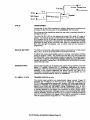
TRIGGER
OUTPUTS
(1 & 2):
The control panel contains two programmable trigger outputs. Trigger #1
terminals are P1-VBELL(+) & P1-T1(-) and for Trigger #2 PI -VBELL(+) &
P1-T2(-). See programming question #07, location 4 for valid trigger types. BY
DEFAULT TRIGGER #1 IS ENABLED FOR SMOKE DETECTOR POWER,
15(+) & 16(-).
WHICH CAN ALSO BE OBTAINED FROM TERMINALS
TRlGGER#2 CANNOT BE SELECTED FOR SMOKE POWER. NOTE: In order
to connect devices to the triggers use connector XL-2GTC (trigger cable).
Unless otherwise specified, the trigger output is normally floating and actively
sinks on activation. Connect to terminal 15 (+) to obtain a POSITIVE reference
point. For UL installations, the trigger outputs shall be connected to devices
rated to operate over the range from 10.1 -14.0 VDC at 50 mA.
XL-2G Hookup&
Installation
Manual Page 12
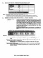
2,3.
AUXILIARY
DEVICE CURRENT DRAW WORKSHEET
Smoke Detector
Glass Break Detector
M
w
n
u
I
NOTE: *Only applies if device is powered from control terminals 15 (+) &12 (-).
w If using devices such as PIR’s, smoke detectors, etc., refer to the specifications for that particular
device’s current draw. If the total current draw exceeds 500mA, then use an additional power supply.
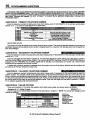
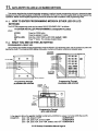
2.4.
WIRING INFORMATION
KEYPADS & OTHER
DEVICES
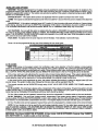
FOR KEYPADS & OTHER DEVICES
If single or multiple devices are connected to a single 4-wire or 2-wire run (“daisy
chained”) to the control terminals, determine the current drawn by the unit(s)
connected to the single wire run, then refer to the Wiring Run Table below to
determine the maximum wire length that can be safely used for each wire size.
In some cases, the total current drawn may result in a value not shown in the
table. For example, if you plan to use #22 gauge wire and the total current drawn
is 400 mA (a value between 300 mA and 500 mA), the maximum wire length
you should use is approximately 65 ft. (a length between 50 and 80 ft.). Other
maximum wire lengths for values of current not shown in the table can be
calculated in a similar manner.
Maximum wire lengths for a device that is “homerun” to the control can
also be determined from the table, based on the current draw of that device
alone.
Examples:
1. What is the maximum distance for f XL+600SM keypad drawing 30 mA using #20 gauge wire?
L/sin the fable above, the keypad can be placed no greater than 750 ft. away from the
pane.7
2. What is the maximum distance for 3 keypads (one 6805& two 6615) drawing 180 mA (60 mA each) using
#20 gauge wire connected m a single wre run?
Using the table above, the farthest keypad can be placed no greater than 292 ft. away
from the panel.
3. What is the maximum distance for 5 smoke detectors drawing 0.25 rnA (5 microA each) using # 22 gauge
wire connected in a single wire run?
Using the table above, the farthest smoke detector can be placed no greater than 500 ft.
away from the panel.
XL-2G Hookup&
Installation
Manual Page 13
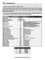
3.
3.1.
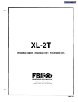
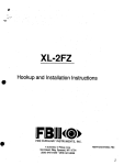
PC BOARD MOUNTING
Mounting the PC Board
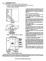
Before mounting the printed circuit board, be certain that the appropriate metal knockouts have been removed. DO NOT
AlTEMPT TO REMOVE THE KNOCKOUTS AFTER THE CIRCUIT BOARD HAS BEEN INSTALLED.
1. Hang the three mounting clips on the raised cabinet tabs. Observe proper clip orientation to avoid damage to the clip
when mounting screws are tightened and to avoid problems with insertion and removal of the PC board.
2. Insert the top of the circuit board into the slots at the top of the cabinet. Make sure that the board rests in the slots as
indicated in the diagram shown below.
3. Swing the base of the board onto the mounting clips.
4. Place the washer provided over the wire jumpers located within the middle of the PC board. Secure the PC board to
the middle mounting clip of the enclosure through the washer using the screw provided.
5. Secure the remaining sides of the PC board to the enclosure using the screws provided.
NOTE: The front face of the enclosure can, be completely removed from the enclosure to gain unrestricted access to the
control panel during installation. The front of the enclosure can be removed as follows
1) Open the enclosure to its fully extended position (approx. 90 degrees)
2) Lift the mntrol panel door and remove the door from the enclosure.
XL-2G Hookup&
Installation
Manual Page 14
4.
KEYPAD MOUNTING
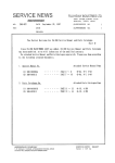
4.1.
XL4600RM METAL KEYPAD
1- Create an opening and mount a standard double
gang box.
2- Secure keypad to double gang box as shown in
diagram below. NOTE: The double gang box shodd
be mounted flush with the wall in order for the key~ d
screws to fit.
NOTE: For UL installations, mount the XL4600RM to
an earth grounded outlet box.
FLUSH MOUNTING
WITH MOUNTING
RING (Using the XL4600TR)
m
●
00
-}”-.
:
●
:>;00
0000
e
. . 00CIO
: clam
●
●
‘“% ‘---”
SURFACE
MOUNTING
C3
e @
(Using optional XL4600RMBX)
1- Create the desired opening where keypad is to be
mounted, using the inside of the mounting ring as a
template. NOTE: This opening should be made
between studs.
2-Secure mounting plate to wall through the four outer
holes using suitable mounting hardware (not
provided).
3-Connect keypad wiring to control panel and secure
the keypad to the mounting ring using the four painted
screws provided.
1- Depending on type of installation run the keypad
wiring out of the rear, top bottom or sides of the
backbox.
2-Attach backbox to wall at desired height
[~
MOUNTING
3- Insert XL4600RM keypad into backbox and secure
with the four screws provided.
[g
KEYPAD
“\
IN CONtiOL
<
PANEL ENCLOSURE
1- Remove keypad knockout from front of metal box
enclosure as shown.
2- Insert XL4600RM
enclosure.
into opening from front of
3- Secure keypad to enclosure using the four painted
metal screws and nuts provided.
XL-2G Hookup&
Installation Manual Page 15
4.2.
XL4600SM
KEYPAD
The XL4600SM Keypad may be surface mounted in the following ways:
A. Directly to a control panel having a keypad cutout on the front of its enclosure.
B. Directly to a single or double gang electrical junction box.
>. Directly to a wall or other surface.
1. Remove the keypad cover assembly from the rear
mounting plate. Insert a small screwdriver blade in the
COVER PRY-OFF SLOTS at the lower edge of the
keypad (see Diagram 2 ) and twist to pry off the cover
assembly.
2. Mount the rear plate (see Diagram 3).
NOTE: The plate is correctly oriented when its part
number, molded into the plastic, is upright.
A. MOUNTING
ENCLOSURE:
I
DIRECTLY
TO CONTROL
PANEL
If the control panel has a keypad cutout on the front
face of its enclosure, remove the cutout and mount the
plate to the enclosure’s face via HOLES “A” ( see
diagram 3) and the four screws and nuts provided.
NOTE: The XL2B attack-proof enclosures does not
contain a keypad cutout.
B. MOUNTING DIRECTLY TO AN ELECTRICAL
JUNCTION BOX:
The plate can be mounted directly to a single or double
gang electrical junction box. Use the screw holes
provided and HOLES “B for a single gang box or
HOLES “A” for a double gang box.
\
m
\
r
MM
I
A
1
C. MOUNTING DIRECTLY TO A WALL OR OTHER
SURFACE
Diagram
2: 00~0M
VIEW OF KEYPAD
Provide a wiring hole in the mounting surface. Position
the plate’s WIRING OPENING over the hole and
mounting plate, using HOLES “A and/or “B” in
conjunction with appropriate mounting hardware (not
provided) for the type of surface.
3. Complete the keypad wiring as required for the
control with which the keypad is to be used.
4. Replace the keypad cover assembly on the rear
plate. Starting at the upper edge of the plate, engage
the plate’s two HOLDING HOOKS (see diagram 3) into
the recesses provided for them inside the upper edge
of the cover assembly and snap the lower edge of the
cover assembly and snap the lower edge of the cover
onto the two SNAP HOOKS at the lower edge of the
plate.
NOTE: (Optional) If desired, cover and plate can be
further secured together by inserting a screw
(provided) into the SLOT at the keypad’s lower edge.
O@rsm
3: RCAR
MO!JUTWO
PLATE
NOTE: When surface mounting the keypad, and using screws with heads larger than the screws provided with the unit,
place electrical tape over the screws to prevent them from interfering with the keypad operation. In the future the back plate
of the keypad will provide additional countersinking for screws with larger heads.
XL-2G Hookup&
Installation
Manual Page 16
MOUNTING 6805 and 6615 KEYPADS
4.3.
Keypad mounting is identical for both the 6615 LED and 6805 LCD versions. Keypads can be surface mounted or flush
mounted as described below. NOTE: After mounting the 6805 LCD Keypad at eye level, you can adjust the display intensity
level to suit the user by adjusting the intensity control located behind the keypad door.
1. Select a mounting location and place the rear plate
of the keypad on the wall. Mark the location of the
cutout for the keypad wiring cable.
2- Create a keypad opening . Connect the keypad
wiring to the control panel w/ 4-wire connector.
3- Place the keypad wiring through the cutout and
secure the back plate to the wall (see diagram).
4-Connect the keypad wiring connector to the keypad
and place the keypad on the mounting plate attached
to the wall.
5- Secure the keypad to the rear mounting plate by
attaching the 5/8 inch screw provided in the lower hole,
located behind the keypad door.
RECESSED MOUNTING
●
1- Select a mounting location. For recessed mountkw
this must be betwe~n two studs. The rear mountin~
plate is not used for recessed installations.
2- Create an opening in the wall exactly 4 inches high
by 5 13/16 inches wide.
s ‘%8-—*
I
4“”
3-Turn over the keypad and remove the Phillips head
screw (item 1 on diagram) in the upper left hand side
of the keypad printed circuit board. NOTE: This screw
is located immediately to the left of the keypad
connector.
I
4-Attach the black metal mounting strap to the rear of
the keypad as follows (see diagram);
- Face the pointed end of the mounting strap facing the
keypad front. This will be used to latch onto the inside
of the wall.
- Place the small white plastic spacer underneath the
mounting strap. Secure the mounting strap using the
5/8 inch Phillips head screw (supplied) and the plastic
spacer to location 1.
7
I
Y
%
5-Connect the white plastic tab into the round opening
immediately behind the keypad door. Place the longer
Phillips head screw (included) through the opening
inside the keypad door and begin to tighten the screw.
Tighten the screw and leave the tab in a down position.
QQ
)QN,
+
- Secure the other end of the strap (location 2 on
diagram) to the white plastic opening using the Phillips
head screw removed in step 2.
;)’b\l
6- Run the keypad wiring to the control panel and
,
7- Place the keypad into the wall opening with the side
contammg the black metal strap first until it grabs the
t::;:::keypad
8-After inserting the side of the keypad with the metal
strap, insert the other side into the opening until the
entire keypad is firmly in the wall.
9- Tighten the screw inserted in step 5.
XL-2G Hookup&
Installation
Manual Page 17
5.
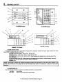
KEYPAD LAYOUT
7
a
34s+
6-
“ ‘‘ ~
“
“
- ‘ ,
Q
to
1-
“ : ●$\
“l:A\\ll
I=aE=+—L
..
Il”wllllm%i-+’:
bs!dL-. -.-.-7
XL4600RM
Keypad
XL4600SM
Keypsd
/“
&
,
wlsl@)15LEo
2
)
Keypsd
1) ZONE STATUS LEDS
These- LEDS display the current zone status including alarms, bypasses, troubles and faults. Each condition will cause
these LEDS to operate differently as follows:
ALARMS Fast Blink (approx. 150 ms. ON -150 ms. OFF).
TROUBLES Slow Pulse (approx. 600 ms. ON -600 ms. OFF).
BYPASSES Wink (100 ms. ON -900 ms. OFF). Zone bypasses are displayed as a very slow wink of the
zone LED light.
FAULTED ZONES Solid ON. Faulted zones are the lowest priority indication. Faulted burglary zones are
displayed with the LED solidly ON while the system is disarmed.
NORMAL OFF
N“OTE: Upon Entry to disarm the system the keypad sounder will annunciate to warn the user to disarm it. In
additon, the respective zone LED(s) will be ON to indicate zones which are violated (ex: entry door and motion
detector).
2) ARNVDISARM LED
This LED indicates whether the system is currently armed (ON) or disarmed (OFF).
Fast Blink
Alarm Mode
Fail to Communicate with Central Station
Slow VVmk
XL-2G Hookup&
Installation
Manual Page 18
3) STAY LED
This LED displays whether the system has been armed in the STAY mode or the STAY/lNSTANT mode. If the INSTANT
LED is ON and the STAY LED is ON, then the system is in the STAY/lNSTANT mode. If the INSTANT LED is OFF and the
STAY LED is ON, then the system is m the STAY mode only. STAY/lNSTANT is enabled in programming question 05, location
4. In either mode the STAY LED indicates the following:
ON
Interior zones are bypassed
Interior zones are normal
OFF
4) INSTANT LED
This LED displays whether the system has been armed in the INSTANT or STAY/l NSTANT mode, meaning that the system
is currently armed, all delay zones are instant and all interior zones are bypassed. If the STAY LED is OFF and the INSTANT
LED is ON, then the system is in the INSTANT mode. If the STAY LED is ON and the INSTANT LED is ON, then the system
is in the STAY/lNSTANT mode. NOTE: See programming question 05, location 4.
Delay zones are currently instant
ON
Delay zones are normal
OFF
5) AC/LOW BA’ITERY LED
This indicator light displays the current power status of the panel as follows;
AC is present
ON
No AC, running on battery backup
OFF
Low battery condition detected
Slow Blink
6) READY LED
This LED displays whether the system is ready for arming. The READY light is common to all BURGLARY ZONES with
the following indications:
System ready to be armed
ON
System not ready to be armed
OFF
Indicates Installer programming mode
Slow Blink
Alarm Memo~ Mode
Fast Blink
7) STAY BUITON
The STAY button enables arming the system, excluding zones programmed as interior zones. This will provide exterior
protection of the location while allowing full access throughout the interior.
8) BYPASS BUTTON
The BYPASS button is used to temporarily exclude protection to a specific zone.
9) INSTANT BUITON
If enabled, the INSTANT button enables arming the system in the INSTANT mode and with the STAY button it enables
arming the system in the STAY/lNSTANT mode. NOTE: INSTANT mode is enabled in question #05, location 4.
10) CODE BUTTON
The CODE button is used to enter the installer programming mode and entry of user codes.
11) LCD DISPLAY
The LCD display shows the current status in a two line by twelve format.
12) KEYPAD AUXILIARY KEYS (XL41600SM KEYPAD ONLY)
Pressing the two keys (top & bottom) labeled “P at the same time initiates a CS transmission, if programmed, of PANIC,
AUXILIARY or FIRE, annunciates the keypad sounder and turns on the bell output. If not programmed to transmit, these keys
can only result in a local warning as follows (see question 05, location 1):
Keypad Souder - Steady for PANIC, Pulsing for FIRE and AUXILIARY
Bell Output - Steady for PANIC, Pulsing for FIRE
NOTE: See the Keypad Emergency Conditions section for alternate auxiliary keys.
XL-2G Hookup&
Installation
Manual Page 19
5.1.
KEYPADSOUNDER
The keypad sounder annunciates differently to indicate the following conditions:
CHIRP - Keypad sounds a short chirp to confirm each keystroke.
STEADY - The keypad will make a steady sound during entry time, and/or during burgla~ alarm.
CHIME - steady 1 second tone (SYSTEM DISARMED ONLY).
ACKNOWLEDGE
- Upon successful entry of a certain commands the system will sound for approximately
half a second.
PULSING - A ulsing sound approximately half a second ON then OFF) indicates a trouble condition such as
AC loss, Low # attery, or Fire$ one.
NEGATIVE ACKNOWLEDGMENT
- U on entry of an ille al command the keypad will sound four short
bee s. For example, If attempting to deFme a new user an! the master user ISnot entered, four short beeps
will 8e made mdlcatmg that the command was unsuccessful.
SOUNDER RINGBACK - Several short beeps to indicate successful communication to the Central Station.
This occurs for all s!gnals, excluding ambush and silent zones.
FAST PULSING SOUNDER- Sound enerated during entry time period AFTER an alarm cmndition ha+
occurred and.the system reached belFcutoff. A pulsing sounder will follow the bell output on Fire conditions.
Trouble condlbons also generate a pulsing sounder and may be silenced through entry of a vahd user rode.
NOTE: The keypad is non~perational
if none of the LED’s are lit and the keypad does not beep when keys are
pressed. This is an indication that service is required. Consult the troubleshooting section of this manual.
6.
6.1.
SYSTEM OPERATIONS
POWER UPISYSTEM RESET
SYSTEM STABILIZATION MODE: Upon initial powerup of the system, all of the lights on the LED keypad(s) will
go ON and then go OFF for approximately 2 min. 10 sees and/or the LCD keypad(s) will display STAND BY! for
approximately 2 min. 10 sees. This occurs on a total powerup (if ARMED or DISARMED in its prior state) or
after a system reset. If the totai system power is lost then upon power restoral, the system wili return to the
previous arming state. The 2 min. 10 sees. interval is used to aliow motion detectors (interior zones) to
stabilize on power up in order to prevent false alarms. THIS OPTION CAN BE DISABLED BY PUTTING A
JUMPER BETWEEN TERMiNALS 13 AND 12 ON POWER UP. IF DiSABLED, THEN THE POWER UP RESET
TIME IS APPROXIMATELY
5 SECONDS.
6.2.
ARMING THE SYSTEM
The system can be armed only if all burglary zones are good (not faulted). On LED based keypads this requires that the
READY LED is on.
On LCD keypads the following message will appear
n
TO ARM: Enter any programmed four digit user. NOTE: The factory default for user #1 is 1234.
The ARMED LED will iight and the user may exit through an exiffentry zone for the time period programmed as the exit
delay. The system can be armed without the backup battery being wnnected, however the AC/LB light will flash.
LCD Based keypads wili display:
XL-2G Hookup&
Installation Manual Page 20
STAY ARMING
6.3.
TO ARM: Press the STAY BUTTON followed by a four digit user code.
The ARMED and STAY LEDs will light on LED based keypads.
LCD based keypads will display:
D
The system is armed at this time with all programmed interior zones excluded.
6.4.
INSTANT ARMING
TO ARM: Press the INSTANT BUITON followed by a four digit user code.
The ARMED and INSTANT LEDs will light on LED based keypads.
LCD based keypads will display:
m
The system is armed at this time with all programmed delay zones instant this eliminates the exiffentry time delays.
NOTE: This option is enabled in programming question 05, location4.
6.5.
STAY/lNSTANT
ARMING
TO ARM: Press the INSTANT then STAY buttons and a four digit user code.
The INSTANT STAY mode will arm the system with the characteristics of both the INSTANT and STAY modes. The system
will be armed with the interior zones bypassed and the delay zones instant.
LED keypads will have the ARMED, STAY and INSTANT LEDS lit. NOTE: This option is enabled in programming question
05, location4.
LCD keypads will display:
m
6.6.
DISARMING
TO DISARM: Press any valid four(4) digit user code and ARMED LED will extinguish.
If an alarm condition exists or had occurred while the system was armed, the zone LED(s)(s) and the READY LED will be
blinking rapidly. This ALARM MEMORY condition can be cleared by entering a valid user code or using the asterisk (*) key.
6.7.
RESET
After an alarm occurs, the system enters alarm memory mode either after bell time-out or by a user entering a valid user
code silencing the bell and keypad buzzer. Alarm memory and communications failure can be cleared by entering a
valid user code. If a fire alarm occurs, then clearing alarm memory resets the smoke detectors for approximately 8 seconds,
In addition, you can use the ● key to act as a reset in addition to using a valid user code for clearing Fire Alarms
Only. THIS OPTION IS ALWAYS ENABLED.
6.8.
BYPASS
Bypassing is performed to temporarily exclude zones which are faulty or not ready from activating the system.
If Quick Bypass is not enabled, then press the BYPASS button followed by any valid four(4) digit user code,
followed a number 1-8, which represents the respective zone to be bypassed.
EXAMPLE: BYPASS ZONE 2 (Assume user code of 1234)
BYPASS 1234 2
Subsequent bypasses can be made by pressing the BYPASS button followed by another zone number within a ten second
period. After this ten second period it will be necessaty to enter the entire command including the user code.
After a successful bypass the keypad sounder will sound the acknowledge beep, and the respective zone LED will WINK
SLOWLY.
XL-2G Hookup&
Installation
Manual Page 21
The bypass rules are:
. FIRE zones cannot be bypassed
. 24 hour zones can be bypassed, however they CANNOT be unbypassed if they are violated.
●
Zones can only be bypassed while the system is disarmed, at which time visual indication will be displayed.
. Bypass signals are transmitted to the Central Station UPON ARMING if a bypass code has been programmed.
I NOTE: Zones which are bypassed are not protected when the system is armed.1
QUICK BYPASS
6.9.
Quick bypassing is a programmable option (see question 05, location 2 of the programming sequence) and allows the
user to bypass zones without using a user code.
Press the BYPASS button followed by a number 1-6, which represents the zone to be bypassed.
Example: To bypass zone 2
BYPASS 2
6.10.
AUTO UNBYPASS
All burgla~ zones which are bypassed can be automatically unbypassed upon system disarm, assuming no other
zone(s) had been in alarm. 24 hour zones which have been bypassed will be unbypassed only if they are normal.
THE AUTO-UNBYPASS FEATURE IS ALWAYS ENABLED.
6.11.
MANUAL UNBYPASS
This function removes an existing bypass from a currently bypassed zone. The procedure is the same as bypass.
6.12.
USER CODE PROGRAMMING
Users codes can be entered or modified directly through the keypad. The system contains up to six user codes (4 digits
each) with the followina armlications:
r
.,
NOTES: Only the master user (user number 1) can program or modify other users. Therefore, do not misplace this code.
Should you misplace you must perform a user code default. Refer to the Installer Modes section.
1. User Number 1- programs all user codes (1-6); cannot be deleted.
2. User Number 6- can be programmed as an ambush code if there is an ambush CS transmission code programmed
into question #16, locations 1 & 2. In this mode, entry of the user #6 code will ARM or DISARM the system and transmit the
ambush code to the Central Station. Furthermore if opening/closing by user reporting is programmed, user number 6 will be
reported along with the ambush code. If no CS code is defined in question #16, then user number 6 will be a normal user
code.
whe~e)
ADD OR CHANGE USERS: [CODE] [USER] [USER #] [USER ID]
[CODE]
Press CODE button
[USER]
~USER#]
Enter Master User ID code (user #1)
Press Desired user to be programmed (l-6)
[USER ID] Enter Four digit user code. Valid digits are O-9
Example: Define user #3 with an ID of 7493. (Assume master user code is 1234).
An acknowledgment
acknowledgment
CODE 123437493
sound (steady tone) verifies
a successful
sound (4 short tones) indicates unsuccessful
XL-2G Hookup&
user code
programming.
Installation Manual Page 22
programming.
A negative
If additional user programming is necessary, repeat the procedure listed above. If a dialing format is programmed which
transmits opening/closing by user ID, each user will report the respective user number.
I NOTE: User code programming
6.13.
can be ONLY performed while the system is DISARMED. I
USER DELETION
User codes (2 -6) can be deleted directly through the keypad. Once deleted their values will be null.
whe~O DELETE USERS: [CODE] [USER] [USER ~ r]
[CODE]
[USER]
[USER #]
r]
6.14.
Press CODE button
Enter Master User ID code (user #1)
Press the desired user number being deleted.(2-6 .
NOTE: User #1 cannot be deleted, but it can be c Aanged.
Press the * (asterisk) button
KEYPAD EMERGENCY
CONDITIONS
The system has the ability to transmit four separate keypad emergency conditions as follows:
For example, the 24 hr keypad panic can be initiated by pressing the # and * keys at the same time. The panic condition
can be silent (no bell output) or audible based on the programming option. NOTE: The default value for panic is audible.
In addition to the keystrokes, the keypads contain dedicated function keys for the auxiliary conditions. These keys can be
activated by pressing both keys at the same time (see section 4).
Audible panic, Fire and Audible Auxiliafy can be RESET BY ENTERING ANY VALID USER CODE.
XL-2G Hookup&
Installation
Manual Page 23
7.
QUICK COMMAND MODES
The end user can perform the following commands (if programmed):
NOTE: On-line Download is not documented in the end user manual because it will only be done when the end user is in
communication with someone at the downloading computer.
7.1.
QUICK ARMING (#1)
If programmed (see programming question #05, location 2), then quick arming will be permitted. Quick arming allows
arming the system without entry of a user code and will report as user #7 to the CS if a 2 digit transmission format is defined.
NOTE: The system must be in ready mode. A user code is required to disarm the system.
7.2.
QUICK FORCE ARMING (#2)
If programmed (see programming question #05, location 2), then quick forced arming will be permitted. Quick force arming
allows arming the system without entry of a user code and bypass any zones that are not ready. It will report user #7 to the
CS if a 2 digit transmission format is defined. NOTE: To disarm, the user code is required.
7.3.
TOGGLE CHIME (#6)
This quick command is enabled in question 05, location 4 by selecting User On-line Downloading. If any zones are
programmed with a chime option (see programming questions #10 -#1 5), then # 6 will turn the system chime ON or OFF
depending on its original state. NOTE: This will toggle the chime feature for the entire system. Since there are no visual
indications on the keypads after toggling the chime, you must be aware of its present state. NOTE: The installer must first
enable the chime option for any zone requiring chime.
7.4.
ON-LINE DOWNLOAD
(#9)
If programmed (see programming question #05, location 4), then the user can initiate a remote communications session
with the CS Downloading computer at the control panel location. Typically, a remote communications session is initiated by
the CS. On-line downloading allows the user to call the office, discuss the action required and allow the CS operator to
complete the request while on-line, no additional telephone call is needed. On-line connection can be made as follows:
1- User dials the CS Downloading modem telephone line from the premises telephone line that the alarm system uses.
Connection would be made with a person at the CS Downloading computer and the account to be downloaded would be
verbally identified. The CS mmputer will be placed into a mode where it is attempting to establish a connection with the site.
2- Next, the user will be instructed to enter #9 on the keypad which will cause the control panel to behave as if it received
a request for a remote communications session and will look for the standard panel to CS protocol.
3- Once the standard’connection is made, the remote communications session can take place (upload, download, remote
commands).
4- User hangs up the telephone to prevent interference which may affect upioad/download data. The downloader software
will automatically terminate the connection after remote communications end.
XL-2G Hookup&
installation
Manual Page 24
8.
INSTALLER MODES
There are 4 installer modes in the panel.
where:
TO ENTER INSTALLER MODES:
Press the CODE button
Press the asterisk ~) button
Enter the 4 digit installer code (default= 2468)
Press the single digit indicating the installer mode as follows:
1 Installer Keypad Programming
Press 1 & 3 (at the same time)
SYSTEM DEFAULT
USER CODE DEFAULT
Press 7 & 9 (at the same time)
2 System Log View
3 Unattended Download
4 On-1ineDownload
[CODE]
r]
[INSTALLER]
ml
8.1.
INSTALLER
[CODE]r][lNSTALLER]~]
MODE 1 (INSTALLER KEYPAD PROGRAMMING)
Enters the installer into keypad programming mode. Refer to the Keypad Programming Section of this Manual. NOTE:
There exists an option in the EZ-Mate Downloader Software to inhibit keypad programming. If selected, then a negative
acknowledgment (4 short beeps) will be heard after attempting to enter this mode. The software has another option (Default
Lockout) to inhibit another installer from defaulting the panel and entering keypad programming. This prevents hostile acmunt
takeovers.
8.1.1.
INSTALLER MODE 1 (SYSTEM DEFAULT)
Any of the system keypads (LED& LCD) can initiate a system default of the system by pressing the”1” and “3” keys
at the same time, while in the programming mode. The system will then default (revert to factory program values) and go
through the reset sequence and THE SYSTEM WILL UNDERGO THE WARMUP TIME SEQUENCE. A system default can
also be done by removing power (AC & DC), shorting JP1 & JP2, reapplying power (with JPI & JP2 still intact) waiting 8
seconds, and then removing short with power still applied. NOTE: A programming option can be selected through the EZ-Mate
Downloader Software known as Default Lockout. If selected, then a system default reset will change all of the programmable
options with the exception of the CSID (a code used by the software to identify the panel during remote connections) and the
installer code. This prevents hostile account takeovers.
8.1.2.
INSTALLER
MODE 1 (USER CODE DEFAULT)
The user codes can be reset to factory default values (User Code 1 = 1234) by pressing the “7” and “9” keys at the
same time, while in the programming mode. The user codes will default and the system will go through the reset sequence
and THE SYSTEM WILL UNDERGO THE WARMUP TIME SEQUENCE.
8.2.
INSTALLER
MODE 2 (SYSTEM
LOG VIEW)
The system retains the past 2 alarm memory conditions; this can contain from 1-6 alarms per arming cycle or
up to 12 alarms for two arming cycles. LED keypads will display alarms as fast blinking zone lights along with a fast blinking
ready (RDY) light. In both keypad types (LCD& LED), the display will show the events starting from the oldest event. Pressing
of the ‘W key will advance the log to the most recent alarm in memory. To exit from the system log view mode press the “*”
key. NOTE: As the log is advanced, the LCD keypad will scroll through all zones that were in alarm for the event. The system
log cannot be cleared by the keypad. It can only be cleared by the Downloader Software. On LCD keypads the following
appears:
EEYl
TO EXIT THE SYSTEM
LOG VIEW MODE: Press the asterisk
exit, enter a valid user code.
8.3.
INSTALLER
MODE 3 (UNATTENDED
key ~). However,
if the asterisk
key ~) does not
DOWNLOAD)
The unattended download function is intended to allow installation of the control panel and then have the control panel
dial the telephone number of CS Downloading Computer to be downloaded without the need to have the operator present.
Basically the CS Downloading computer telephone number will be programmed into the callback number (question 03) and
XL-2G Hookup&
Installation
Manual Page 25
an identification number (same as the account # in the Downloader Software) will be programmed into the Secondary
Telephone (#question 02). NOTE: These are temporaty values since they will be reprogrammed after downloading.
Unattended download requires the following sequence:
1- The PC operator must select Unattended
DOWNLOAD in the Downloader Software Main Menu.
2- Enter unattended download mode: [CODE]~] [INSTALLER][3],
3- The system will now enter keypad programming, question 01. Press the “*” key first followed by the “O” key and then
the “3” key. This will go to programming question 03. Enter the telephone number of the Central Station Downloading computer
(each digit followed by the ‘W key, ex: l#2#3#etc.) into this question (12 digits max). This phone number should be the same
as the CS Callback number (question #03 from keypad programming if the panel is programmed for callback).
4- Proceed to question 02 through the sequence”* 02”. Next enter the desired account number (each digit followed by
the ‘W key). This will be used by the CS downloading computer to determine the proper account information to download to
this subscriber. The account number must be 6 digits in length and it is the Downloaders Account designator not the account
number that will be communicated to the receiver. For IDs less than 6 digits long you must enter leading 0s to make the
number 6 digits long. Example: for ID 345 enter 0#O#O#3W#5#.
5- Press the “STAY” key to exit programming mode. The control panel will now dial the telephone number entered into
the callback number. The downloading computer must be placed into the Unattended Communications option from the main
menu. Upon connection with the computer the customer account number programmed in step 3 will be obtained and the
system will perform the desired download operation. NOTE: The CS Downloading computer must be waiting in the unattended
communications option and preprogrammed with the account information in order for the unattended download to be
functional.
INSTALLER MODE 4 (ON-LINE DOWNLOAD)
kIthis mode, the installer can initiate a remote communications session with the CS Downloading
8.4.
computer at the control
panel location. Typically, a remote communications session is initiated by the CS, On-line Downloading allows the installer
to call the office (from the same telephone line as the panel), discuss the action required and allow the CS operator to complete
the request while on-line, no additional telephone call is needed. On-line connection can be made as follows:
1- Installer completes installation and attaches a handset to telco terminals (tip& ring) or uses the standard home telephone
to dial the CS Downloading modem telephone line. Connection is made with a person at the CS Downloading computer and
the account to be downloaded would be verbally identified. The downloading computer operator will select the On-line Remote
Operations from the device menu
2- The installer should enter the on-line download sequence: [CODE] ~] [INSTALLER] [4] or use the end-user mmmand
of # 9, if enabled. This will cause the control panel to behave as if it received a request for a remote communications session
and will look for the standard panel to CS protocol.
3- Once the standard connection is made, the necessaty remote communications sessions can take place (upload,
download, remote mmmands).
4-Hang up the telephone or remove headset from the line to prevent interference which may affect upload/download data.
The downloader soflware will automatically terminate the connection after remote communications end.
9.
SYSTEM PROGRAMMING
The system can be programmed in any one of the following methods:
. Directly through keypad (XL4600RM, XL4600SM, 6805 or 6615)
. EZ-MATE PC DOWNLOADER model 7700 remotely
NOTE: The EZ-Mate downloader has not been tested for UL applications.
This manual describes system programming via the keypad. The other programming devices include documentation
describing their programming procedures.
Keypad programming is accomplished by understanding and completing the PROGRAMMING SHEET located in the back
of this manual.
There are 22 total programming questions numbered 00-21, Additional programming questions are available for the
programmable zone descriptors when LCD based keypads are used (see programming questions #22 - #27).
Within each question there are several locations labeled LI, L2, etc. for data entry.
The system is shipped from the factoty with SPECIFIC DEFAULT VALUES which were selected for a typical installation.
If the default values are suitable for your installation then programming can be simplified. The default values are listed with
each programming question and in the SYSTEM DEFAULT section of this manual.
XL-2G Hookup&
Installation
Manual Page 26
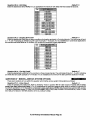
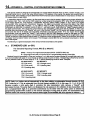
I ().
PROGRAMMING QUESTIONS
This section of the manual defines the programming questions along with the values expected for each question. BEFORE
USING THE PROGRAMMING SHEET, FILL THE SYSTEM PLANNING WORKSHEETS AT THE END OF THIS MANUAL.
Then, Complete the Programming sheet and then enter the data through the keypad as explained in the section titled
Data Entry Through the Keypad. DO NOT ATTEMPT TO ENTER DATA BEFORE COMPLETELY FILLING OUT
PROGRAM SHEET.
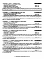
QUESTION 01
PRIMARY TELEPHONE
NUMBER
Enter the telephone number (including area code and/or dialing prefix IF NECESSARY) of the primaty central station
receiver in L1 - L12. Enter the valid digits from the table below.
REPORTING ROUTE:
The system will report all signals to the primary receiver phone number. The panel will alternate between the primary and
secondary receivers (if the semnd phone number is programmed) for a maximum of 8 attempts each until the signal has
been acknowledged.
QUESTION 02
SECONDARY
TELEPHONE
NUMBER
Enter the telephone number (including area code and/or dialing prefix IF NECESSARY) of the seconda~ central station
receiver in L1 - L12.
Enter the valid digits from the table in question 01. The semndaty telephone number will be used if the panel is unable to
reach the Central Station via the primary number. This is known as BACKUP reporting. If the SPLIT REPORTING feature is
programmed? then OPENING and CLOSING signals will be directed to the secondary CS number only, while all other
conditions will be reported to the primafy number.
If neither split or backup reporting is necessary then this question may be left as factory defaulted and all conditions will
be routed to the Primafy Telephone number only.
QUESTION 03 CALLBACK TELEPHONE NUMBER
Enter the telephone number (including area code and/or dialing prefix if necessary) for this control panel to reach the
callback location. The callback number is the optional location of the EZ-Mate Downloader where the control panel will call
during a remote communications (upload/download etc) session. During remote communications the programming device
and the control panel will first confirm the CS security code. If valid, communications can begin. If a callback number is defined,
the control panel will the hang up and dial the callback number. Enter the valid digits from the table in question 01. NOTE:
For no callback capability enter MAAMMMM.
QUESTION 04
DIALER OPTIONS
There are 4 locations (L1-L4) within this question which define various dialer and system options as follows:
DEFAULT = 1
Question 04, L1 - Dialer Formats
which
Enter the digit for the desired dialer format from the table below in location L1. NOTE: The checkmark highlights
-options are sel~cted.
NOTE See
Question #04,
location 3 to select
specific Cs
Reporting Format
Message Length
and specific
Dialing Pulse Type.
XL-2G Hookup&
Installation
Manual Page 27
Question
04, L2 - CS Receiver
De fauit = 6
Type
Enter the digit for the desired receiver type from the table below in location L2. NOTE: The checkmark highlights which
odions are selected.
NOTE: UL compatible receivers: FBI CP220 (all formats), ADEMCO 685, Silent Knight 8520,9000, RADIONICS.
Question 04, L3 - CS Format Message Length, System Swinger Shutdown
& Puise Type
De fauit = O
Enter the digit for the desired message length from the table below in location L3. NOTE: The checkmark highlights
NOTE: Please consult your Central Station manager to determine the formats and message lengths which are accepted
by the receiver. European dialing format has not been tested by UL.
SWINGER SHUTDOWN - If selected, then 3 activations of the same zone within the same arming interval will not activate
the bell or the dialer. This applies only to burglary zones as well as 24Hr. Audible zones. For UL installations Swinger Shutdown
must not be selected.
DIALING PULSE TYPE - Specifies how this control will perform pulse dialing (U.S. Pulse or European Pulse) when CS
transmissions are enabled. NOTE: European Pulse has not been tested for UL installations.
I NOTE: For more information
on CS Reporting
Formats
XL-2G Hookup&
refer to Appendix
Installation
A at the back of this manual. I
Manual Page 28
Question 04 L4- K.P. Panic, CS Split Repotiing,
Cancel Bell Ringback & System Bell Test
Default
❑
1
Enter the digit for the desired system options from the table below in location L4. NOTE: The checkmark highlights which
options are
KEYPAD SILENT/AUDIBLE PANIC - Determines whether the keypad panic condition ( * & # from the keypad) will activate
the bell and the keypad buzzer. In either case a signal will be transmitted to the Central Station if a panic code has been
programmed. NOTE: The keypad panic condition can be activated through question #05, location 1.
SPLIT REPORTING - The split reporting option will direct all opening and closing signals to the secondary receiver
telephone number. All other conditions (alarms, troubles, restores etc.) will adhere to the reporting route described in question
01. If split reporting is selected then the secondaty receiver telephone number MUST be programmed.
CANCEL CODE BELL RING BACK - If AUDIBLE, the bell will RING BACK for 1 second when the cancel code is sent,
provided that some other transmission would not cancel this event (ex silent panic). If SILENT, the bell will not RING BACK.
BELL TEST - If this option is selected the bell will be activated for one second upon successful arming. This option is
required for UL Commercial Burglary applications.
QUESTION 05
KEYPAD CONDITIONS
This question contains four locations (L1-L4) for various keypad definable options.
Question 05, LI - Keypad Panic, System Stay Mode Dialer Delay&
Bell Instant
Default = 1
Enter the digit for the desired system options from the table below in location L1. NOTE: The checkmark highlights which
options are
m
NOTE: Keypad Fire and Keypad Auxiliary are always enabled. Auxiliary Audible/Silent selection refers to keypad sounder
only (not the bell). Keypad Fire is always Audible. Keypad Panic is Audible or Silent based on quest. #04, location 4.
STAY MODE DIALER DELAY - If selected this will give the system an additional delay as follows: When the system is
armed in the STAY mode, any control zone alarm (delay, interior, perimeter) will cause the dialer to be delayed by 40
seconds. A delay zone WIII first follow the entry delay and then the 40 second delay. Also, during the 40 second dialer delay
XL-2G Hookup&
Installation Manual Page 29
the keypad sounder will be activated and the bell depending on whether it is selected (see STAY MODE BELL INSTANT).
When the system is not armed in the STAY mode, the 40 second delay is disabled. If not selected, the 40 second delay during
the STAY mode will be disabled.
STAY MODE BELL INSTANT - This is selected in conductionwith the STAY MODE DIALER DELAY option, If selected,
the bell will sound instantly during the 40 second delay. If not, the bell will also follow a 40 second delay.
Default = 2
Question 05 L2 - hlisc Options
Enter the digit from the table below in location L2. NOTE: The checkmark highlights which options are selected.
,~.,
,
r
!
,~?w’i
,
I
,
I
,
!
u
u
,
II
ZONE 7 INPUT: PANIC or KEYSWITCH - This option determines whether connections 8 & 10 on the control panel will
be used as a panic input (audible or silent) or a keyswitch input. NOTE: If keyswitch is selected and the transmission mde
sends a user rode, then user code #7 will be transmitted.
AC LINE FREQUENCY - This selects which AC input frequency (60 HZ or 50 HZ) is present for the AC based system
Clock.
QUICK COMMANDS ENABLED - Determines whether the Quick Commands (Quick Forced Arm, Quick Arm and Quick
Bypass) are enabled. NOTE: Do not program this option for UL installations.
Default = 7
Question 05 L3 - CS Test Time Interval
If CS Test Repott is enabled, this option determines the test time interval. NOTE: The checkmark highlights which options
are selected.
CS TEST TIME INTERVAL - Select from NONE, 1 hour, daily (24 hour), weekly, 27 days, 60 days or 90 days. NOTE: All
test time intervals are reset after a successful CS Test report only. NOTE: To intiate the CS test sequence some time in
advance from the time the installation is completed within the same day refer to question #21. CS test reporting code is entered
in question#18, locations 3 &4.
EUROPEAN RING DETECT - Use this option if a European Telephone System is used only. This option changes the ring
detection frequency used for automatic answer mode for remote (Downloading) purposes only according to the programmed
ring count (see programming question #07, location 2). If selected, the ring detection frequency range is 10- 90Hz. If not
selected, the frequency range is 16- 90Hz.
XL-2G Hookup&
Installation
Manual Page 30
Default = O
Question 05, L4 - Rest Foil Loop/User On-line/CS Test Ringback
Enter the digit from the table below in location L4. NOTE: The checkmark highlights which options are selected.
RESTORE AFTER BELL - Restores will be transmitted after the loop has returned to normal after bell cutoff, or upon
system disarming regardless of the loop status.
RESTORE FOLLOWS LOOP - This option will transmit restores immediately upon zone restoral while the system is armed,
or upon system disarm regardless of the loop status.
USER ON-LINE &CHIME TOGGLE ENABLED - This option indicates whether the end user command (#9) for the on-line
download will be enabled. This command would allow an end user to be instructed how to initiate an on-line download and
possibly prevent a service call. This also controls the user chime toggle enable. If enabled, then the user will be able to toggle
the system chime.
CS TEST RING BACK - Normally, after a CS Test Report has reached the Central Station, a sounder ringback can be
heard from the keypad indicating a successful communication to the CS. If SILENT is selected, then NO sounder ringback
will be heard from the keypad after a CS Test Report. If AUDIBLE is selected, then a sounder ringback will be heard from
the keypad after a CS Test Report.
INSTANT ENABLED - This option permits the INSTANT arming option (INSTANT or STAY/lNSTANT
mode) to be used.
QUESTION 06 SYSTEM TIMEOUTS
There are 4 locations (L1-L4) within this question which define various system timing options as follows:
Default = 6
Question 06 L1 - Entry Delay 1
Enter the desired entry delay time. Refer to Exit/Entty Times below for valid choices. If zones 1-3 are delay zones, then
they follow entry delay 1. For UL applications the maximum entrance delay shall not exceed 45 seconds for household
applications or 15 seconds for commercial burglary applications. NOTE: See programming question #07, location 1 for Entry
day 2.
XL-2G Hookup&
Installation Manual Page 31
Default = 6
Question 06 L2 - Exit Delay
Enter the desired exit time. NOTE: For UL applications the maximum exit delay shall not exceed 60 seconds.
Default = 5
Question 06 L3 - Burglary Bell Cutoff
Enter the desired bell cutoff time on alarm conditions for burgla~ and panic in 3 minute intervals. The valid range of input
is 1- F, with F indicating an infinite burg bell cutoff. Example 3 = 9 minutes. For UL installations in commercial applications
the minimum bell cutoff shall be 15 minutes, or 6 minutes for household burglary applications.
Default = F
Question 06 L4 - Fire Bell Cutoff
Enter the desired bell cutoff time for fire renditions in three minute intervals. The valid range of input is 1- F, with F indicating
an infinite fire bell cutoff. Example 3 = 9 minutes. For UL installations the minimum fire bell cutoff time shall be 6 minutes.
QUESTION
07
MISCELLANEOUS SYSTEM OPTIONS
There are 4 locations (LI -L4) within this question which define various system timing options as follows:
Default = 2
Question 07 L1 - Entry Delay 2
Enter the desired entry delay time. Refer to Exit/Entry Times in question #06 for valid choices. If zones 4-6 are delay
zones, then they follow entry delay 2. For UL applications the maximum entrance delay shall not exceed 45 seconds for
household applications or 15 seconds for commercial burglary applications. NOTE: See programming question #06, location
1 for table of applicable values. IF ZONE 6 IS PROGRAMMED AS A FIRE ZONE FOR BELL SUPERVISION, THEN TO USE
EXIT DELAY 2 SELECT EITHER ZONE 4 OR 5 AS A DELAY ZONE.
XL-2G Hookup&
Installation
Manual Page 32
Question 07, L2 - Ring Count&
Default = C
System Diaier Deiay
Enter the digit from the table below in location L2. NOTE: The checkmark highlights which options are selected.
. ..... . .
3 RINGS
8 RINGS
10 RINGS
12 RINGS
44 RINGS
I
.0 RINGS
—
#
1
REMOTE COMMUNICATIONS
RING COUNT - is a the number of rings for the control panel to pickup for a remote
communications session. This should be selected to a value that does not interfere with normal operation of the panel
location.The default value is 8 rings. NOTE: A value of Omeans that remote programming will be disabled. Select from the
choices above; the values are in multiples of two.
SYSTEM DIALER DELAY - If selected, all controlled zones will have a 15 second dialer delay, allowing the user to ABORT
theCS transmission. If not selected, any alarm condition will result in an immediate transmission that cannot be abofted.
NOTE: For UL installations this option must not be selected.
Defauit = O
Question 07, L3 - Trigger W Output
The smoke power terminals (15 & 16) or P1, T1 can be used as trigger #1 output. If a fire zone requiring fire verification
is used in the system, the trigger should be programmed as “O”. If the fire device does not need a power reset, or no fire zone
type is selected, the trigger can be programmed as shown in the Trigger Types Chart. NOTE: Smoke Power Output can only
be enabled for trigger #1.
Defauit = 5
Question 07, L4 - Trigger #2 Output
A secondaty Trigger output can be obtained ftom P1, T2. The following Trigger Type Chart shows the valid entries.
I NOTE: Unless otherwise specified, the trigger output Is normally floating and actively sinks on activation. [
QUESTION 08 ACCOUNT NUMBER 1
Enter the three(3) or four(4) digit subscriber account number for Central Station phone number 1 in iocations L1-L4. If a
three(3) di it number is used then enter an A in iocation L4. Valid entries are O-9,and B-F. The value A is interpreted as the
null value ror account numbers.
XL-2G Hookup& Installation Manual Page 33
QUESTION 09 ACCOUNT
NUMBER 2
Enter the three(3) or four(4) digit subscriber account number for Central Station phone number 2 in locations L1-L4. If a
three(3) di it number is used then enter an A in location L4. Valid entries are O-9, and B-F. The value A is interpreted as the
null value ?or account numbers. If the second phone number is not used this question can be left as factory defaulted.
THIS ACCOUNT NUMBER MUST BE ENTERED
NUMBER FOR BACKUP OR SPLIT REPORTING.
10.I.
IF YOU HAVE PROGRAMMED
A SECOND
RECEIVER
PHONE
ZONE PROGRAMMING
Questions 10-15 represent all the options related to programmable zones 1-6. Each question contains four(4) locations
L1-L4. The first two locations (Ll & L2) define the zone type and options. The second two locations (L3 & L4) define the alarm
“
code transmitted to the Central Station for that zone. -ZONE TYPES
Zones 1-6 cal
NOTE:
For
24
Hour Zone types
see next psge.
?3
BURGLARY
(CONTROLLED)
.
I
I
1
.
I
I
I
u
ZONES
DELAY - This is the indusby standard exiffentry zone. When the system is armed exit time begins. After exit expires, any
subsequent violation of this zone will begin entry time. If the system is not disarmed within the programmed entry time an
alarm will occur. The keypad sounder will annunciate steadily during entry time, unless there had been an alarm condition,
at which time it will pulse. Delay zones will activate instantly when the system is armed using the STAY/lNSTANT mode if
enabled. Delay zones employ the Exit Error Warning feature described in the note below.
INTERIOR - All interior zones have exit delay time upon system arming. Furthermore, all interior zones will have entry
delay time if a delay zone is violated first. If this zone is violated first however,it will generate an immediate alarm, Interior
zones are bypassed if the system is armed in the STAY MODE. Interior zones employ the Exit Error Warning feature described
in the note below.
PERIMETER
- This zone type (sometimes known as INSTANT) will generate an alarm when violated while the system is
armed.
EXIT ERROR WARNING - At the end of exit time a 1 second window is started. If any delay or interior zones
are violated after arming within this window (exit time expires and entry time starts) the burglary bell and
keypad sounder will be turned on forcing the user to enter their code preventing a false alarm transmission.
This helps avoid the common false alarms that take place after arming the system.
XL-2G Hookup& Installation Manual Page 34
BURGLARY ZONE OPTIONS
RESTORE - This option is selected for all burgla~ zones by enabling the restore report code (question 19, location 2).The
programmed restore code will be reported upon bell cutoff, assuming the loop is restored unless Restore Follows Loop is
selected in question #05, location 4. The restore code will also be reported if the system is disarmed during an alarm. NOTE:
Restore is not selectable by zone.
BYPASS IN STAY - This option allows zones to be bypassed when the system is armed in the STAY mode.
CHIME - If this option is selected the keypad sounder will annunciate for 1 second when this zone is violated in the disarmed
mode.
DIALER DELAY - If this option is selected (quest. #07, location 2), then the system (all zones) will allow a 15 second delay
before dialing, allowing the end user to ABORT the transmission. If this option is not selected, any alarm condition will result
in an immediate transmission that cannot be aborted. NOTE: For UL installations dialer delay may not be used.
DAY FEATURE - If a zone with this option is violated while the system is DISARMED, the keypad sounder and zone LED
will pulse for as long as the violation remains. In addition, the SYSTEM TROUBLE CODE will be transmitted to the central
station. THE SOUNDER CAN BE SILENCED through entry operation of any valid user code. While the system is armed, a
DAY zone will act as an alarm when violated.
FAST ZONE - If enabled, then the zone response will be 10 msec. If not selected, it will be 280 msec.
Zones 1-6 can be programmed for any one of the following 24 hour zone types:
24 HR. ZONES
FIRE - FIRE zones on the system contain Fire Verification Logic. Upon detection of the first violation, smoke detector
power will be reset for a period of 8 semnds. After this time period, power is restored. For a period of 5 seconds the fire zone
will not be scanned allowing the smoke detectors to settle. Future violations within a two minute period will result in a PULSING
BELL OUTPUT, RAPID PULSING ZONE LED,and IMMEDIATE transmission to the CS. Fire signals cannot be aborted.
Entry of any valid user code will silence the sounder, bell and reset smoke detector power. If the system detects that the
fire zone is still violated within 2 minutes of power reset, the zone LED will pulse slowly to indicate a fire trouble. Thereafter,
smoke detector power will be reset every 4 minutes automatically in an attempt to clear the fire zone.
In the event the fire zone experiences an open, the system indicates fire trouble by pulsing the keypad zone LED and
sounder slowly. The system trouble code ( followed by the zone code) will be reported to the CS.
The keypad sounder can be SILENCED through entry of ANY VALID USER CODE. NOTE: FIRE ZONES cannot be
bypassed.
24 HR. ALARM - This zone type is always active, independent of the system arming status. Programming options include
audible (STEADY BELL) or silent (NO BELL or keypad indications). Upon violation the zone LEDS will pulse rapidly (audible
zones only) and an immediate CS transmission will occur which cannot be aborted.
24 Hour Alarm zones can be bypassed, however they cannot be unbypassed if a violation exists on the zone terminals.
24 HR. TROUBLE - This zone type is always active, independent of the system arming status. Programming options
include audible (PULSING KEYPAD SOUNDER) or silent. Upon violation the zone LED will pulse slowly. Trouble condition
must exist for 15 seconds before a transmission will occur. The keypad display and sounder will clear upon zone restoral.
24 Hour Trouble zones can be bypassed, however they cannot be unbypassed if a violation exists on the zone terminals,
NOTE: 24 hour trouble is not to be used for fire and bur Iary detection zones. 24 Hour silent alarm zones are not to be
used for perimeter protection. THE SOUNDER MAY BE Sf LENCED THROUGH ENTRY OF ANY VALID USER CODE.
NOTE: IF ZONE 6 IS PROGRAMMED AS A FIRE ZONE FOR BELL SUPERVISION, THEN TO USE EXIT DELAY2 SELECT
EITHER ZONE 4 OR 5 AS A DELAY ZONE.
WARNING: Fire Zones CANNOT BE BYPASSED. 24 Hour zones CAN BE BYPASSED, however, they CANNOT
BE UNBYPASSED if a violation exista on their terminals.
XL-2G Hookup&
Installation Manual Page 35
As previously specified locations L3 and L4 of the zone questions represent the alarm code that will be reported to the
central station.
NOTE: Zones will transmit
to the Central Station unless these digits are defined as AA for any individual zone,
or the local dialer orXion is selected for all zones in auestion #04, location 1.
Based on the dialer format selected enter the alarm code as follows:
STANDARD FORMAT (3X1 or$4Xl : Enter the desired single digit alarm code in location L3 for the specific
zone. The value placed m L4 WIIIno1 be used.
EXTENDED (3X1 Ext. or 4X1 Ext.): Enter the desired first digit of the alarm code in location L3 for the
specific zone and the second digit m L4.
PARTIAL EXTENDED (3X1 Part. Ext. or 4X1 Part. Ext.): Enter the desired digit in both locations L3 and L4
foy thes ecific zone. This will generate a single di it transmissions for alarms and troubles (the second digit
will not ! e used) and an extended tra,nsmlssions ?or all system conditions such as restores, bypasses,
openmgs/closmgs, etc. (the second dlglt will be used).
4x2: Enter th.eodesi~edfirst di it of the alarm code in location L3 and the second digit in L4 for the specific
zone. Both dlglts will be use 8 for all transmissions.
~NOTE: For more information on CS Reporting Formats refer to Appendix A at the back of this manual. [
QUESTIONS 10-15 ZONES 1-6
There are 4 locations (Ll -L4) within each of these questions which define the operation of the zones. Enter a 2 digit
number in locations LI and L2 from the zone chartfor thedesiredtypefor this zone. Enter the desired alarm code
in locations L3 and L4 for this zone relative to the dialer format selected.
QUESTION
10 ZONE 1 TYPE & CS CODE
Question
10, L1 & L2 - Zone 1 Type
Default =20
Question
10, L3 & L4 - CS Code for Zone 1
Default =31
Zone 1 = Delay (Entry/Exit) w/CS reporting code= 31
QUESTION 11 ZONE 2 TYPE & CS CODE
Question
11, L1 & L2 - Zone 2 Type
Question 11, L3 & L4 - CS Code for Zone 2
Zone 2 = Interior Follower w/CS reporting code= 32
Default =40
Default =32
QUESTION 12 ZONE 3 TYPE & CS CODE
Question
12, L1 8 L2 - Zone 3 Type
Default =10
Question
12, L3 & L4 - CS Code for Zone 3
Default =33
Zone 3 = Instant (Perimeter) w/CS reporting code= 33
QUESTION 13 ZONE 4 TYPE & CS CODE
Question73, LI & L2 - Zone 4 Type
Default =10
Question
Default =34
13, L3 & L4 - CS Code for Zone 4
Zone 4 = Instant (Perimeter) w/CS reporting code= 34
QUESTION
14 ZONE 5 TYPE & CS CODE
Question
14, L1 & L2 - Zone 5 Type
Default =10
Question
14, L3 & L4 - CS Code for Zone 5
Default =35
Zone 2 = Instant (Perimeter) w/CS reporting code= 35
NOTE:
If zones 1 - 3 are programmed as DELAY zones, they follow ENTRY DELAY 1. If zones 4 - 6 are
programmed as DELAY zones, they follow ENTRY DELAY 2,
XL-2G Hookup& Installation Manual Page 36
QUESTION 15 ZONE 6 TYPE & CS CODE
There are 4 locations L1-L4 in this question as follows
Question 15, L1 & L2 - Zone 6 Typs
Default =10
Question 15, L3 & U - CS Code for Zone 6
Default =36
Zone 6 = Instant (Perimeter) w/CS reporting code= 36
NOTE: If zone 6 is programmed as a FIRE zone, Bell Supervision is enabled. See Bell Output Terminal
connections for description.
QUESTION 16 CS CODES for AMBUSH and AC LOSS
There are 4 locations LI-L4 in this question as follows:
Question f 6, Lf & L2 - Ambush Code
Default = AA
if an ambush mde is defined, then user number 6 is the ambush code. The same rules apply here regarding dialer format.
If transmission is not desired, then program AA in locations LI & L2. NOTE: AMBUSH transmissions are immediate and not
abortable.
Question 76, L3 L?L4 - AC Loss Code
Default
❑
AA
The same rules apply here regarding dialer format. If transmission is not desired, then program AA in locations LI & L2.
NOTE: AC LOSS is reported 15 minutes after deteti!on.
QUESTION 17 CS CODES for PANIC and LOW BATTERY
There are 4 locations L1-L4 in this question.
Question 17, L7 & L2 - Panic Code
Defauit = 22
The same rules for programming regarding dialer format apply here. If transmissions are not desired, then program AA in
locations 1 &2. NOTE: PANIC transmissions are immediate and not abortable.
Defauit = AA
Question 77, L3 & L4 - Low Battery Code
The same rules for pro ramming regarding dialer format apply here. If transmissions are not desired, then program AA in
locations 1 &2. LOW BA4 ERY transmissions will be reported 4 minutes after detection. LOW BATTERY RESTORE CODE
will be reported WITHIN 4 minutes after detection of GOOD BAITERY condition.
QUESTION 18 CS CODES for OPEN/CLOSE and CS TEST
There are 4 locations L1-L4 in this question.
Question 78, Lf - Opening Code
Default = A
Question 18, L2 - Ciosing Code
Defauit = A
LI is the single digit OPENING CODE. L2 is the single digit CLOSING CODE. Entry of AA into these two locations means
that openings and closings are not desired. If a dialer format other than standard is programmed then the second digit
transmitted will be the user number.
Defauit = AA
Question 18, L3 & L4 - CS Test Code
L3 - L4 is the CS Test CODE. Entry of AA means that CS Test is not enabled. If CS Test code is selected then ANY valid
transmission will reset the CS Test timer.
QUESTION 19 CS CODES for BYPASS, RESTORE, TROUBLE and CANCEL
~
There are four(4) locations LI - L4 in this question.
Defauit = A
Question 19, LI - Bypass Code
L1 is the single digit system BYPASS CODE that will be reported to the central station if a zone is bypassed, UPON
ARMING. Entry of an A means that bypasses are not transmitted. If a two digit dialing format has been selected then the
Bypass code will be followed by the programmed second digit of the zones rode.
De fauit = A
Question 19, L2 - Restore Code
L2 is the single digit system RESTORE CODE reported to the central station. Restores will be reported for all burglaty or
24 hour zones by enabling this code (entry of any code except A) . Entry of an A means that restores are not transmitted. If
a two digit dialer format has been programmed then the restore code will be followed by the programmed second digit of the
zones code. NOTE: Restore is not selectable by zone.
Question 19, L3 - Troubie Code
Defauit = F
L3 is the single digit system TROUBLE CODE reported to the central station. This code will be reported on DAY TROUBLE
and any FIRE TROUBLE. if a two digit format has been programmed then this code will be followed by the second digit of
the respective zones code.
XL-2G Hookup& Installation Manual Page 37
Default = 8
Qu~tbn 19, L4 - Cancel Code
L4 ISthe single digit system CANCEL CODE reported to the central station. This code will be sent if after a violation of a
controlled zone, a user mde is entered. If the zone is still violated, entry of a user code will transmit the oancel code. If the
zone is programmed far restoral, then the restore code will be transmitted when the loop status has returned to normal. An
entty of A in this field indicates that cancel codes are not transmitted. [n formats requiring 2 digits, the user number functions
as the second digit. NOTE: An option exists to make the Canel Code Bell Ringback either AUDIBLE or SILENT (see question
#04, location 4). -
QUESTION
20
CS CODES for KEYPAD FIRE and KEYPAD AUXILIARY
There are 4 locations L1-L4 in this question.
Question 20, L1 & L2 - Keypad Fire Code
Default = AA
L1 - L2 is the alarm code that will be transmitted uDon activation of the kevDad fire condition (t)ressina
the 7 & 9 kevs
,,
“----,––onthe keypad). This code can vary from any of the zones which are programm~d as fire.
Question 20, L3 & L4 - Keypad Auxiliary Code
L3 - L4 is the code transmitted to the CS for keypad aux. condition ( 1 & 3 from the keypad).
Default = AA
NOTE: These keypad emergency conditions are optional and can be enabled within question 05 of the programming
sequence. If either or both of these transmissions are not desired, program their respective locations AA.
QUESTION
21
CS TEST OFFSET
There are 4 locations LI-L4 in this question.
Question 27, Lf & L2 - CS Test offset Hours
Default = 18
Question 27, L3 & L4 - CS Test Offset Minutes
Default = 3C
This option allows the installer to initiate the automatic CS Test sequence some time in advance from the time the
installation is completed within the same day. For example, if the installation is completed at 6:00 PM and the test is desired
at 1:00 PM, then program an offset of 7 hours. Enter hours and minutes in hexadecimal. The valid range for hours is 01-18
(24 hours) and the valid range for minutes is 01- 3C (60 minutes). NOTE: An option exists to make the CS Test Ringback
keypad sounder either AUDIBLE or SILENT (see question #05, location 4).
QUESTION
00
INSTALLER
CODE
There are 4 locations L1 - L4 in this question. Enter any 4 digit (O-9 installer code desired). This code is used to ENTER
the system programming mode via the keypad.
Typically each installing company would use a unique installer code in order to prevent unauthorized people
from gaining access to their panels.
XL-2G Hookup& Installation Manual Page 38
I I . DATA ENTRY VIA LED & LCD BASED KEYPADS
This section describes the physical keystrokes necessafy to perform keypad programming and how to interpret the data
displayed on the LED based keypads (XL4600RM, XL4600SM or 661 5) and on the LCD keypad (6805) during programming
operations. NOTE: Actual keypad programming should be performed after completion of the programming sheet.
I I.I.
HOW TO ENTER PROGRAMMING
KEYPADS
MODEVIA EITHER LED OR LCD
The SYSTEM programming mode can be entered WHILE DISARMED ONLY as follows:
where:
TO ~/VT~~
[CODE]
r]
[INSTALLER]
[1]
11.2.
INSTALLER
PROGRAMMING:
[CODEl~][lNSTALLER][l]
Press the CODE button
Press the asterisk (*) button
Enter the 4 DIGIT INSTALLER CODE (default= 2468)
Press”1” button. This indicates installer Mode 1.
WHAT YOU SEE ON THE LED KEYPAD
PROGRAM MODE = READY LED:
Upon entering the installer keypad programming mode the READY LED will slowly pulse, and will continue to pulse until
leaving this mode. The remaining LEDs display the question number and location contents as indicated below:
LOCATION
Cowv.ws
Programming Through
XL4600SM LED KEYPAD
Programming Through
XL4600RM LED KEYPAD
v
m
Programming Through
6615 LED KEYPAD
In the diagrams above the question number is obtained by ADDING the values of all zone LEDS that are ON.
= QUESTION 01
EXAMPLES:
Zone 1 0/4, Zones 2-5 OFF
= QUESTION 03
Zone 1 ON, Zone 2 ON, Zones 3-5 OFF
Zone I ON, Zone 3 ON, Zone 4 ON, Zones 2 and 5 OFF= QUESTION 13
XL-2G Hookup& Installation Manual Page 39
QUESTIONNUMBERS= ZONE LEDS:Thereare22total questions, with multiple data entry locations.
Zone LEDS 1 through 5 display the current QUESTION NUMBER (not the specific location within each question) as follows:
In the diagram shown on the following page, the question number is the total you get when you ADD the values of all
LEDS that afi ON.
EXAMPLES:
Zone 1 ON, Zones 2-5 OFF
= QUESTION 01
Zone 1 ON, Zone 2 ON, Zones 3-5 OFF
= QUESTION03
Zone 2 ON, Zone 3 ON, Zone 4 ON, Zones 1 and 5 OFF = QUESTION 14
LOCATION CONTENTS = SYSTEM STATUS LEDS
The remaining status LEDS (ARM,STAY,lNSTANT,AC/LB) display the DATA that resides in EACH location within the
current question. As per the diagram which follows and explanation above, the value located next to each LED must be
ADDED to calculate the total data, for each location.
EXAMPLES:
Arm ON, Stay,lnstant,and AC/LB OFF
Arm ON, Stay ON, Instant and AC/LB OFF
=3
The following chart displays binary values that you will see on these LEDS for the letters A-F which may be entered in
some locations of the program sheet.
10 Stay &AC/LB = ON
A
11
B
Arrn,Stay, &AC/LB= ON
12
Instant, & AC/LB= ON
c
13
D
Arrn,lnstant, & AC/LB= ON
14
E
Stay,lnstant, & AC/LB= ON
15
F
Arm, Stay,lnstant, & AC/LB = ON
11.3.
WHAT YOU SEE ON THE LCD KEYPAD
Upon entering the installer keypad programming following display will appear
EEcl
The display shows the current question number (QUES), the location within the question (L:) and the current value within
that location (DATA =). This corresponds to the programming worksheet.
11.4.
HOW TO ENTER DATA
This section of the manual describes the physical keystrokes to enter the data written on the program sheet.
MOVEMENT BETWEEN QUESTIONS
System program mode starts with question 1 displayed. RANDOM JUMPS TO
ANY QUESTION CAN BE MADE BY PRESSING THE* (ASTERISK) BUTTON
AND THE 2 DIGIT QUESTION NUMBER.
Questions can be accessed randomly or sequentially.
Example: Jump to question 07= Press* 07
MOVEMENT WITHIN QUESTIONS
The proper question number will be displayed by the zone LEDS and the other
status LEDS will display the contents of the FIRST location in that question.
The zone LEDS display the question number and the other status LEDS display
the contents (data) within each location. MOVEMENT FROM LOCATION L1
TO THE NEXT LOCATION WITHIN ANY QUESTION CAN BE PERFORMED
BY PRESSING THE # (POUND) BUTTON.
The other status LEDS will display the contents of each location as this button
is pressed.
DATA ENTRY
To alter the value in any location , enter the desired DIGIT from the program
sheet, and press the # button.
NOTE: THE # BUITON MUST BE PRESSED AFTER THE ENTRY OF the DESIRED DIGIT. THE SYSTEM WILL
MOT PROGRAM THE DIGIT UNTIL THE POUND (#) BUTI’ON IS PRESSED, THEREFORE IF A MISTAKE IS MADE
T CAN BE CHANGED.
XL-2G Hookup&
Installation
Manual Page 40
Numeric entries O-9can be performed by Pressing the respective keypad
button. Entries of A-F require 2 keystrokes as follows:
Press the CODE button followed by 14 for values A-F.
VALUE
KEYSTROKES
VALUE KEYSTROKES
D
CODE 1
CODE 4
A
E
CODE 5
B
CODE 2
F
CODE 6
CODE 3
c
Example: Enter an A = Press CODE followed by 1.
After all programming has been mmpleted, PRESS THE STAY BUTTON TO
EXIT THE SYSTEM PROGRAM MODE. All the LEDS will turn ON for
approximately 10 seconds, before the system returns to normal daily operation.
The keypad will beep between keystrokes. In addition, a beep will be generated
confirming advancement between questions numbers.
EXIT SYSTEM PROGRAM MODE
QUESTION ACKNOWLEDGMENT
Four beeps will be generated if an invalid input is entered. Upon entry of invalid
input you are positioned at the same question number and location as prior to
the input error.
SUMMARY OF SYSTEM PROGRAMMING
XL-2G Hookup& Installation Manual Page 41
11.5.
ZONE DESCRIPTOR
PROGRAMMING
The LCD based keypads have the capability to display 12 character zone descriptors which can be programmed directly
through the keypad. These descriptors are entered as programming questions 22-27.
NOTE: These questions can only be accessed by an LCD keypad, or the EZ-Mate Downloading Software.
The zone descriptor questions are as follows:
QUESTION
22
ZONE 1 DESCRIPTOR
QUESTION
23
ZONE 2 DESCRIPTOR
QUESTION 24 ZONE 3 DESCRIPTOR
QUESTION
25
ZONE 4 DESCRIPTOR
QUESTION
26
ZONE 5 DESCRIPTOR
QUESTION 27 ZONE 6 DESCRIPTOR
Example: To program the descriptor for zone 3 enter * 23, to access question 23.
When programming the English zone descriptors the following techniques are used to program the characters:
1[lNSTAN~
1
[CODE]
1
II
Moves the cursor to the LEFT one space.
IMovesthecursortotheRIGHTOnespace.
1
INCREMENTS
m
r]m
[9]
[#] [9]
the character one at a time at the cursor.
Scrolls forward (UP) through the character set. NOTE:
Pressing any key will stop the scroll.
DECREMENTS the character one at a time at the cursor.
I
Scrolle backward (DOWN) through the character set.
NOTE: Pressing any key will stop the scroll
NOTE: The characters available through the LCD based keypads are as follows:
l“#$YO&’()*+-./Ol
23456789 ;=@ABCDEFGHLJKLMNOpQRsTWVV)(yz
XL-2G Hookup& Installation Manual Page 42
I
I
I
12. SYSTEM DEFAULTS
The system is shipped from the factory programmed with default values. These values have been selected to meet the
requirements of a common installation and may suit your needs.
To reload the factory default values, remove all power from the system (AC & DC). Next shod JP1 to JP2, with
short still intact reapply power (AC then DC), wait 5 seconds then remove short with the power still applied.
The installer can also do a System Default or User Code Default through Installer Mode 1 (refer to the Installer
Modes section of this manual).
NOTE: A programming option exists within the EZ- Mate PC Downloader devices known as DEFAULT LOCKOUT. If this
o~tion is selected then a system default will not overwrite the CSID or installer code rwtion of the moaram. This will trevent
an installer other than the briginal installer from taking over an account without cooperation.
o ‘P*L,4
, , ,,,; . .,
,&
:. >i%??$f~a
,:w:~m,,.b:;;$~iww~~~
‘
.:
$P:M+*
*$,,,
~$
@
@$
“if
:.
.
.;i?
,
~
~~
*?4
,,
7
00
,
,+
.,”
‘,
“ ,,
installer Code
‘ “’”
‘
2468
primary Telephone Number
234AAAAAAAAA
OZ Secondary Telephone Number
AAAAAAAAAAAA
01
AAAA
03 Callback Number
Dialer Options
1601
OS Keypad Conditions
1270
06 System
665F
04
Timeouts
OT Miscellaneous
2C05
System Options
None
None
Touchtone 3X1,20 PPS, 2300 ~
No Parity; Audible K.P. Panic;
Cancel Coda Bell Ring Back Silent U.S. Pulse
Keypad Panic, Silent Auxiliary; H.W. Panic Audible, 80 Hz CS
Test Disabled; Restore Follows Bell, Stay/lnatant Enabled
Entry Delay 1 =30 sec.; Exit Delay= 1 min.;
Burg. Bell Cutoff =15 min.; Fire Bell Cutoff = Infinite
Entty Delay 2 =30 sec.; Ring Count= 8, System Diater Delay;
Trigger #1 = Smoke Povmr Trigger #2= Armed
Number 1
1234
Og Account Number 2
AAAA
None
Zone 1 Type & CS Code
2031
Delay
11 Zone 2 Type & CS Code
4032
Interior Follower
12 Zone 3 Type & CS Code
13 Zone 4 Type & CS Code
1033
Instant Zone; CS Coda= 33
1034
Instant Zone; CS Coda= 34
1A Zone 5 Type & CS Code
1035
Instant Zone; CS Code= 35
08 Account
~
1036
1s Zone 6 Type & CS Code
Zone;CS Code= 31
Zone;CS Code= 32
Instant Zone; CS Code= 36
AAAA
None
CS Codes for Panic/Low Battery
22AA
Panic CS Code= 22
cs codes for Open/Cose & cs Test
AAAA
None
I g CS Codes for By pass, Restore, Trouble & Cancel
AAF8
Trouble CS Code=
ZO CS Codes for Keypad Fire& Auxiliary
AAAA
None
16 CS
IT
18
Codes for Ambush/AC
21 CS Test Offeet
Loss
183C
CS Test offset=
F; Cancel CS Coda=
19 Hours
22
Zone 1 Descriptor
Zone 1
23
24
25
26
27
zone 2 Descriptor
Zone 2
zone 3 Descriptor
Zone 3
LCD KEYPADS ONLY
zone 4’Descriptor
Zone 4
LCD KEYPADS ONLY
LCD KEYPADS ONLY
LCD KEYPADS ONLY
zone 5 Descriptor
Zone 5
LCD KEYPADS ONLY
zone 6 Descriptor
Zone 6
LCD KEYPADS ONLY
XL-2G Hookup&
Installation Manual Page 43
8
13. SUMMARY
13.1.
13.2.
OF KEYPAD FUNCTIONS
USER FUNCTIONS
ARM/NG/DISARMING:
[4 digit user code]
STA YARMING:
[STAYl [4 digit user code]
STA Y/iNSTANT ARMING:
[STA~
BYPASS:
[BYPASS] [4 digit user code] [Zone #]
QUICK BYPASS:
[BYPASS] [Zone #]
USER CODE PROGRAMMING:
[CODE] [Master user code] [user #] [4 digit user code]
USER CODE DELETION:
[CODE] [Master user code] [user #] ~]
QUICK ARMING:
[#] [1]
QUICK FORCE ARMING:
[#] [2]
TOGGLE CHIME:
[?l [61
ON-LINE DOWNLOADING:
[#] [9]
PANIC:
~]&
[#l at the same time
FIRE:
~]&
[9] at the same time
AUXILIARY:
[1] & [3] at the same time
AMBUSH:
[Enter user code 6]
INSTALLER
[4 digit user code]
[INSTANT]
MODES
KEYPAD PROGRAMMING:
[CODE] ~ [Enter installer code] [1]
SYSTEM LOG VIEW
[CODE] fl [Enter installer code] [2]
UNATTENDED DOWNLOAD:
[CODE] ~] [Enter installer code] [3]
ON-LINE DOWNLOAD:
[CODE] ~ [Enter installer code] [4]
SYSTEM DEFAULT:
[CODE] ~] [Enter installer code] [1]
then press [1] & [3] at the same time
USER CODE DEFAULT:
[CODE] ~] [Enter installer code] [1]
then press ~] & [9] at the same time
NOTE: All these functions can be performed from all keypad types (XL4600RM,
if they are enabled.
XL-2G Hookup&
Installation
Manual Page 44
XL4600SM,
6615 or 6805)
14. APPENDIXA
- CENTRAL STATION REPORTING FORMATS
This security system is designed to transmit data to a Central Station Receiver when an Alarm, System Trouble, or an
Opening/Closing occurrs. Due to the many different types of CS receivers in the market, this system can transmit data in
various formats. Each installing company determines which format best suits its needs based on many factors. Of these, the
CS receiver type is a major factor.
In transmitting data to the CS receiver, the first event that occurrs is that the system’s digital communicator will seize the
home phone lines. Then, it will dial the CS#l telephone number (programming question #01). When the CS receiver picks
up the ringing phone line, it will transmit a “Handshake” frequency (either 1400Hz, 2300Hz or HiLo) back to the digital
communicator. After receiving the “Handshake” frequency, the digital communicator will transmit the data in the format
programmed in question #04, locations 1, 2 & 3 (either in Pulse or DTMF). Assuming the CS receiver verifies the data
transmission as valid (after 2 succesful rounds of data or 1 valid parity round), it will transmit a “Kissoff’ frequency back to
the digital communicator. This causes the communicator to stop transmitting, unless more data is available, in which case
additional data transmissions and “Kissoffs” will occurr. After the final “Kissoff, the CS receiver will release the phone line
and process the data to its display and associated peripherals (computer and printer). If for any reason the the digital
communicator, does not receive the “Kissoff”, it will proceed to dial the CS#2 telephone number or dial again the CS#l
telephone number (if CS#2 is not used). It will continue to dial (8 times for each CS telephone number programmed) until a
“Kissoff is received. If atlerdialing 8 times for each CS Telephone number programmed a “Kissoff’ is not received, the system
will display “Communication Failure” at the keypad. This message is cleared after the next successful transmission or by the
user at the keypad.
The following is a general description of the various formats transmitted by this system.
14.I.
STANDARD (3X1 or 4X1)
The Standard Repotting Format: AAA E or AAAA E
where:
AAAA = Three or Four digit Account Number (PROG. QUESTS. #08& 09)
E = Single digit Event code; it is the first of the 2 programmable reporting code digits
Standard format is transmitted in Pulse and involves a 3 or 4 digit account number followed by a sin Ie di it event code.
It can be transmitted with Daritv (1 round of data) or without Daritv (2 rounds of data), A disadvantage o!8this rmat is that it
can only transmit a total o~15 ~~ent codes (O-9: B - F) without i~dentifying zones or users. Examples:
3X1 W/O PARITY
3X1 W/PARITY
12336 (single round)
1233 (Ist round)
1233 (resulting data)
1233 (2nd round)
1233 (resulting data)
4X1 W/PARITY
4X1 W/O PARITY
12343 (Ist round)
123432 (single round)
12343 (2nd round)
12343 (resulting data)
12343 (resulting data)
~NOTE: Parity is a number derived automatically by the dialer utilizing a mathematical formula (modulo 15). Ex:
1233 adds up to 9. This is subtracted from the next highest multiple of 15; in this case, 15-9 = 6. If the CS
receiver accepts a valid parity digit, it considers the data transmission valid, delivers a “Kissoff’ and
processes the data. The parity digit is not displayed. Its only purpose is for validation of data transmitted. It is
not a programmable digit; it is generated automatically by the dialer when the parity option is selected in
programming question #04, location 2. The obvious advantage of using parity is speed. The transmission time
between dialer and receiver is shorter because fewer digits are transmitted with it as opposed to without it.
XL-2G Hookup&
Installation Manual Page 45
4
14.2.
EXTENDED (3X1 EXT. or 4X1 EXT.)
The Extended Reporting Format: AAA EZ or AAAA EZ
where:
AAAA = Three or Four digit Account Number (PROG. QUESTS. #08& 09)
E = Single digit Event code; it is the first of the 2 programmable reporting code digits
Z = Zone or User identifie~ it is the second of the 2 programmable reporting code digits
Extended format is transmitted in Pulse and involves a 3 or 4 digit account number followed by a double digit reporting
code.The only purpose for using the Extended format (sometimes known as Universal or Expanded format) is to be able to
transmit more than 15 codes to the CS receiver. It does this by extending the event code from the previous round of data
resulting in a 2 digit reporting code. It can be transmitted with parity (2 rounds of data) or without parity (4 rounds of data).
There are 15 possible event codes, each of which can have 15 different zone or user identifiers. As a result, a total of 225
individual events can be reported. Examples:
3X1 Ext. W/PARITY
3X1 Ext. W/O PARITY
12336 (Ist round)
1233 (lst round) 1233 (2nd roud)
33315 (2nd round)
3331 (3rd round) 3331 (4th round)
12331 (resulting data) Burglary Zone 1
12331 (resulting data) Burglary Zone 1
4X1 Ext. W/O PARITY
12343
(lst round)
4X1 Ext. W/PARITY
12343 (2nd round)
33331 (3rd round)
33331 (4th round)
123431 (resulting data) Burglary Zone 1
14.3.
123432 (lst round)
333312 (2nd round)
123431 (resulting data) Burgla~ Zone 1
PARTIAL EXTENDED (3X1 PART. EXT. or 4X1 PART. EXT.)
The Patfjal
Extended Reporting Format: AAA EZ or AAAA EZ
where:
AAAA = Three or Four digit Account Number (PROG. QUESTS. #08& 09)
E = Single digit Event code; it is the first of the 2 programmable reporting code digits
Z = Zone or User identifie~ it is the second of the 2 programmable reporting code digits
The Partial Extended format is a combination of both the Standard and Extended formats. It transmits in Pulse a standard
message for alarm conditions and an extended message for restores and other system conditions. To report a standard
message, enter a numerical digit (O- 9) in the first of the 2 digit reporthg code; for an extended message, enter a hexadecimal
digit (B -F) in the first of the 2 digit reporting code. The extended messages are used whenever a zone or user identification
is needed (Bypasses, Restores, Openings/Closings, etc.). It can also transmit with and without parity. Examples:
3X1 Part. Ext, W/O PARITY (Restore)
3X1 Stand.W/O PARITY (Alarm)
123 E (Ist round)
123 E (2nd round)
1233 (Ist round)
EEE 1 (3rd round)
EEE 1 (4th round)
1233 (2nd round)
123 El (resulting data) Burglary
1233 (resulting data) Burglary
14.4.
3X2 or 4X2
The 3X2 or 4X2 Reporting Format: AAA EZ or AAAA EZ
where:
AAAA = Three or Four digit Account Number (PROG. QUESTS. #08& 09)
E = Single digit Event code; it is the first of the 2 programmable repotting code digits
Z = Zone or User identifier it is the second of the 2 programmable reporting code digits
This format is also in Pulse and is an alternative to the Extended format it also transmits a 2 digit reporting code. Its specific
meaning is a 3 or 4 digit account number followed by a 2 digit alarm code. It can be transmitted with parity (1 round of data)
or without parity (2 rounds of data). There are 15 possible event codes, each of which can have 15 different zone identifiers.
As a result, a total of 225 individual events can be reported. It is different from the extended format in the way it transmits.
This is illustrated in the examples below:
3X2 W/O PARITY
3X2 W/PARITY
12331 (lst round)
123315 (Ist round)
12331 (2nd round)
12331 (resulting data) Burglary Zone 1
12331 (resulting data) Burglary Zone 1
XL-2G Hookup& Installation Manual Page 46
15. APPENDIX
B - TROUBLESHOOTING
1. LED or LCD: Keypad
display not lit.
la. A,C. & D.C. power out.
lb. Keypad not powered.
2. LED KP: “AC/LB” light
OFF
LCD KP: “A.C. LOSS”
3. LED KP: “AC/LB”
light
slowly blinking
LCD KP: “LOW BAT”
2a. A.C. power out
2b. Faulty keypad
3a. D.C. power out; no battery
connected
3b. Low battery voltage
4. LED KP: “ARM” light
slowly blinking
LCD KP: “COMM.
disconnected; C.S. Mo.
missprogrammed.
4b. Replace panel.
4c. Consult local telephone
comuanv.
5a. Zone faultedhlystern not
ready to be armed
OFF
READY”
NOT
3a. Check battery connection;
check batt. volt,
(w/transformer disconnected);
check battery fise.
3b. Same as 3a. except volt. >
1lVDC; otherwise let battery
charge: redate batterv.
w/Central Station.
LCD KP: “NOT RDY: ZN
#?! & “sySTEM
2a. Check transformer connection;
check A.C. input volt.
2b. Retdace kewad.
4a. Telephone lines cut or
4c. Faulty telephone lines.
5. LED KP: “ZONE” light
ON& “READY” LIGHT
A.C. input volt. & batt. volt.
(w/transformer disconnected);
check auxiliary fuse.
lb. Check term. 15(+) & 12(-)
for 12VDC.
4a. Failure to communicate
4b. Faulty panel.
FAILURE”
la. Check transformer connection
& battery connection; check
5b. Faulty keypad
5c. Faulty panel
5a. Check loop wiring for either
an open or short & repair;
bad resistor or wrong resistor
value.
5b. Replace keypad
5c. Check zone term. for 3.3
VDC; Bypass zone
temporarily; replace panel.
For more complicated problems consult our Technical Service at (800) 645-5430.
XL-2G Hookup& Installation Manuai Page 47
XL-2G SYSTEM PLANNING WORKSHEET
Name:
* Valid Zone Types are:
Address:
24 Hour Zones
24 Hour Alarm
24 Hour Trouble
Fire
Controlled Zones
Instant/Perimeter
Delay
Interior
I
XL-2G SYSTEM PROGRAMMING WORKSHEET
NAME:
01
ADDRESS:
PRIMARYTELEPHONENUMBER
02 SECONDARYTELEPHONENUMBER
03CALLBACKTELEPHONENUMBER
04DIALEROPTIONS
Wgg
17 PANIC&
05KEYPADCONDITIONS
LOW BAITERY
18 OPEN, CLOSE&
06SYSTEMTIMEOUTS
*,$*]
CS TEST
I
‘~
,,,,’
Em!
07 MISCEL. SYS.OPTIONS
20 KEYPAD FIRE& AUX.
08AccouNT#l
21 CS TEST OFFSET
09ACCOUNT#2
00 INSTALLER CODE
10 ZONE 1 TYPE & CS CODE
@’$~ji~
i,
Imm
11 ZONE 2 TYPE & CS CODE
I,I$2$$?I
12 ZONE 3 TYPE & CS CODE
~fl?$q
13 ZONE 4 TYPE & CS CODE
~~i;i~]
W:l
14 ZONE 5 TYPE & CS CODE
~m~
.:
[m
~“.*$J
Iwl
15 ZONE 6 TYPE & CS CODE
~~~$j$ijj
i~$ii!il
16 AMBUSH&AC
=
LOSS
it..
1$2%$1
E@*il
22 ZONE 1 DESCRIPTOR
23 ZONE 2 DESCRIPTOR
#gj;:/g
~~fjq
. , .,-.
lMM
24 ZONE 3 DESCRIPTOR
25 ZONE 4 DESCRIPTOR
26 ZONE 5 DESCRIPTOR
27 ZONE 6 DESCRIPTOR
PROGRAMMED
BY:
DATE:
WARNING LIMITATIONS OF THIS ALARM SYSTEM
Whilethis system is an advanced design security system, it does not offer guaranteed protection against burgla~, fire or other
emergency.Any alarm system, whether commercial or residential, is subject to compromise or failure to warn for a variety of reasons. For
example:
●
Intruders may gain access through unprotected openings or have the technical sophistication to bypass an alarm sensor or
disconnect an alarm warning device.
●
Intrusion detectors (e.g., passive infrared detectors), smoke detectors, and many other sensing devices will not work
without power. Battery operated devices will not work without batteries, with dead batteries or if the batteries are not put in
properly. Devices powered solely by AC will not work if their AC power supply is cut off for any reason, however briefly.
●
Signals sent by wireless transmitters may be blocked or reflected by metal before they reach the alarm receiver. Even if the
signal path has been recently checked during a weekly test, blockage can occur if a metal object is moved into the path.
.
A user may not be able to reach a panic or emergency button quickly enough.
.
While smoke detectors have played a key role in reducing residential fire deaths in the United States, they may not activate
or provide early warning for a variet of reasons. In as many as 359’oof all fires, according to data published by the Federal
Emergency Management Agency. $ ome of the reasons smoke detectors used in conjunction with this System may not
work are as follows: Smoke detectors may have been improperly installed and positioned. Smoke detectors may not sense
fires that start where smoke cannot reach the detectors, such as in chimneys, in walls, or roofs, or on the other side of
closed doors. Smoke detectors may not sense a fire on another level of a residence or building. A second floor detector, for
example, may not sense a first floor or basement fire. Moreover, smoke detectors have sensing limitations. No smoke
detector can sense every kind of tire every time. In general, detectors may not always warn about fires caused by
carelessness and safety hazards like smoking in bed, violent explosions, escaping gas, improper storage of flammable
material:, overloaded electrical circuits, children playing with matches, or arson. Depending on the nature of the fire and/or
the location of the smoke detectors, the detector, even if it operates as anticipated, may not provide sufficient warning to
allow all occupants to escape in time to prevent injury or death.
●
Passive Infrared Motion Detectors can only detect intrusion within the designed ranges as diagramed
in their installation
manual. Passive Infrared Detectors do not provide volumetric area protection. They do create multiple beams of protection,
and intrusion can only be detected in unobstructed areas covered by the beams. They cannot detect motion or intrusion
that takes place behind walls, ceilings, floors, closed doors, glass partitions, glass doors, or window. Mechanical tampering,
masking, painting, or spraying of any material on the mirrors! windows or any part of the optical system can reduce their
detection ability. Passive Infrared Detectors sense changes m temperature; however, as the ambient temperature of the
protected area approaches the temperature range of 90 to 150F, the detection performance can decrease.
c Alarm warning devices such as sirens, bells or horns may not alert people or wake up sleepers who are located on the
other side of closed or partly open doors. If warning devices sound on a different level of the residence from the
bedrooms, then they are less likely to waken or alert people reside the bedrooms. Even persons who are awake
may not hear the warning if the alarm is muffled by noise from a stereo, radio, air conditioner or other appliances, or by
passing traffic. Finally, alarm warning devices, however loud, may not warn hearing-impaired people or waken deep
sleepers.
●
Telephone lines needed to transmit alarm signals from a premises to a central monitoring station may be out of service or
temporarily out of service. Telephone lines are also subject to compromise by sophisticated intruders.
●
Even if thes stem responds to the emergency as intended, however, occupants may have insufficient time to protect
themselves f rom the emergency situation. In the case of a monitored alarm system, authorities may not respond
appropriately.
●
This equipment, like other electrical devices, is subject to component failure. Even though this equipment is designed to last
as long as 10 years, the electronic components could fail at any time.
The most common cause of an alarm system not functioning when an intrusion or fire occurs is inadequate maintenance. This alarm
system should be tested weekly to make sure all sensors are working properly. Installing an alarm system may make one eligible for lower
insurance rates, but an alarm system is not a substitute for insurance. Homeowners, property owners and renters should continue to act
prudently in protecting themselves and continue to insure their lives and property.
We continue to develop new and improved protection devices. Users of alarm systems owe it to themselves and their loved ones to
learn about these developments.
XL-2G Hookup& Installation Manual Page 50
FBII LIMITED WARRANTY
Fire Burgla~ Instruments, Inc., a Subsidiary of Pittway Corporation, and Pittway Corporation its divisions, subsidiaries
and affiliates (“Seller”), 149 Eileen Way, Syosset, New York 11791 warrants its products to be in conformance with its own
plans and specifications and to be free from defects in materials and workmanship under normal use and service for 5 years
Wornthe date stamp control on the product, or for products not having a date stamp: for 5 years from the date of original
purchase unless the installation instructions or catalog sets forth a shorter period, in which case the shorter period shall apply.
Seller’s obligation shall be limited to repairing or replacing, at its option, free of charge for materials or labor, any product
which is proved not in compliance with Seller’s specifications or proves defective in materials or workmanship under normal
use and service. Seller shall have no obligation under this Limited Warranty or otherwise if the product is altered or improperly
repaired or serviced by anyone other than Seller. For warranty service, return transportation prepaid, to Factory Service, 149
Eileen Way, Syosset, New York 11791.
THERE ARE NO WARRANTIES,
PURPOSE OR OTHERWKE, WHICH
BE LIABLE TO ANYONE FOR ANY
WARRANTY, EXPRESS OR IMPLIED,
IS CAUSED BY THE SELLERS OWN
EXPRESSED OR IMPLIED, OF MERCHANTABILITY, OR FITNESS FOR A PARTICULAR
EXTEND BEYOND THE DESCRIPTION ON THE FACE HEREOF. IN NO CASE SHALL SELLER
CONSEQUENTIAL OR INCIDENTAL DAMAGES FOR BREACH OF THIS OR ANY OTHER
OR UPON ANY OTHER BASIS OF LIABILITY WHATSOEVER, EVEN THE LOSS OR DAMAGE
NEGLIGENCE OR FAULT.
Seller does not represent that the products it sells may not be compromised or circumvented; that the products will prevent any personal
injury or property loss by burglaty, robbe~, fire or otherwise; or that the products will in all cases provide adequate warning or protection.
Customer understands that a properly installed and maintained alarm system may only reduce the risk of a burglary, robbery, fire, or other
events occurring without providing an alarm, but it is not insurance or a guarantee that such will not occur or that there will be no personal
injury or property loss as a result. CONSEQUENTLY, SELLER SHALL HAVE NO LIABILITY FOR ANY PERSONAL INJURY, PROPERTY
DAMAGE OR OTHER LOSS BASED ON A CIAIM THE PRODUCT FAlLED TO GIVE ANY WARNING. HOWEVER, IF SELLER IS HELD
LIABLE, WHETHER DIRECTLY OR INDIRECTLY, FOR ANY LOSS OR DAMAGE ARISING UNDER THIS LIMITED WARRANTY OR
OTHERWISE, REGARDLESS OF CAUSE OR ORIGIN, SELLERS MAXIMUM LIABILITY SHALL NOT IN ANY CASE EXCEED THE
PURCHASE PRICE OF THE PRODUCT, WHICH SHALL BE THE COMPLETE AND EXCLUSIVE REMEDY AGAINST SELLER. This
warranty replaces any previous warranties and is the only warranty made by seller on this product. No increase or alteration, written or
verbal, on the obligations of this Limited Warranty is authorized.
“FEDERAL
COMMUNICATIONS
This equipment
COMMISSION
(FCC) STATEMENT”
has been tested to FCC requirements and has been found acceptable for use. The FCC requires the following statement
for your information.
This equipment generates and uses radio frequency energy and if not installed and used properly, that is in strict accordance with the
manufacturer’s instructions may cause interference to radio and television reception. It has been tested and found to comply with the limits
of Part 15 of FCC Rules, which are designed to provide reasonable protection against such interference ina residentialinstallation.However,
there is no guaranteethat interferencewill not occur in a particular installation. If this equipment does not cause interference to radio or
television reception, which can be determined by turning the equipment off and on, the user is encouraged to try to cowect the interference
by one or more of the following measures:
If using an indoor antenna, have a quality outdoor antenna installed.
. Reorient the receiving antenna until interference is reduced or eliminated.
.
.
Move the radio or television receiver away from the control/ communicator.
●
Move the antenna leads away from any wire runs to the control/communicator.
.
Plug the controlkommunicator into a different outlet so that it and the radio or television receiver are on different branch
circuits.
If necessary, the user should consult the dealer or an experienced radiohelevision technician for additional suggestions.
The user may find the following booklet prepared by the Federal Communications Commission helpful:
“Interference Handbook”
This booklet is available from the U.S. Government Printing Orlice, Washington, DC 20402. Stock No. 004-000-00450-7.
The user shall not make any changes or modifications to the equipment unless authorized by the installation Instructions or User’s
Manual. Unauthorized changes or modifications could void the user’s authority to operate the equipment.
IN THE EVENT OF TELEPHONE
OPERATIONAL
PROBLEMS
In the event of telephone operational problems, disconnect the communicator by removing the plug from the RJ31x jack. Do not
disconnect the phone connection inside the communicator. Doing so will result in the loss of your phone lines, If the regular phone works
correctly after the communicator has been disconnected from the phone lines, the communicator has a problem and should be returned
for repair,lf upon disconnection of the communicator, there is still a problem on your line, notify the telephone company that they have a
problem and request prompt repair service. The user may not under any circumstances (in or out of warranty) attempt any service or repairs
on the system. It must be returned to the factory or an authorized service agency for all repairs.
XL-2G Hookup& Installation Manual Page 51