1
Publication 0300050-07 Rev. c.0
SOI-260
Operator
Interface
IMPORTANT NOTES
1.
READ ALL OF THE INFORMATION CONTAINED IN THIS MANUAL BEFORE YOU
INSTALL THE PRODUCT.
2.
The information contained in this manual applies to hardware and software version 1.0 or later.
3.
This manual assumes a full working knowledge of the relevant PLC.
NOTICE
The products and services described in this manual are useful in a wide variety of applications.
Therefore, the user and others responsible for applying the products and services described herein are
responsible for determining their acceptability for each application. While efforts have been made to
provide accurate information within this manual, Spectrum Controls assumes no responsibility for
the accuracy, completeness or usefulness of the information contained herein.
Under no circumstances will Spectrum Controls be responsible or liable for any damages or losses,
including indirect or consequential damages or losses, arising out of either the use of any information
contained within this manual or the use of any product or service referenced herein.
No patent liability is assumed by Spectrum Controls with respect to the use of any of the information, products, circuits, programming or services referenced herein.
The information contained in this manual is subject to change without notice.
Caution
Spectrum Controls’ devices contain electronic components which are susceptible to damage from
electrostatic discharge. A static charge can accumulate on the surface of ordinary plastic wrapping or
cushioning material. If any Spectrum Controls’ device must be returned to Spectrum Controls, the
following packaging instruction must be followed:
PREFERRED: Use the original packaging material as supplied by Spectrum Controls. Place
the device inside the conductive plastic bag.
ACCEPTABLE: Wrap the device in some type of antistatic material. Antistatic plastic material
can be identified by its pink color, and can be obtained in sheet or bag form.
UNACCEPTABLE: Do not use ordinary plastic film, foam, or styrene chips ("popcorn" or
"peanuts"). These materials can accumulate charges in excess of 10,000 volts, resulting in
possible damage to the Spectrum Controls electronic device.
Antistatic (metallized plastic) bags can be obtained from the following manufacturers:
3M Company
Static, Inc.
Charles Water
(800-328-1368)
(800-782-8424)
(617-964-8370)
Type 2100 bag
8000 Series bag
CP-303 bag
i
SOI-260 OPERATOR INTERFACE MODULE USER MANUAL
LIMITED WARRANTY
Spectrum Controls warrants that its products are free from defects in material and
workmanship under normal use and service, as described in Spectrum Controls
literature covering this product, for a period of 1 year. Spectrum Controls’ obligations under this warranty are limited to replacing or repairing, at its option, at its
factory or facility, any product which shall, in the applicable period after shipment,
be returned to Spectrum Controls’ facility, transportation charges prepaid, and which
after examination are determined, to the satisfaction of Spectrum Controls, to be
thus defective.
This warranty shall not apply to any such equipment which shall have been repaired
or altered except by Spectrum Controls or which shall have been subject to misuse,
neglect or accident. In no case shall Spectrum Controls’ liability exceed the purchase
price. The aforementioned provisions do not extend the original warranty period of
any product which has either been repaired or replaced by Spectrum Controls.
Copyright and TradeMark information:
SOI, SOI-PRO, and SOI-SPS are trademarks of Spectrum Controls, Inc.
IBM is a registered trademark of International Business Machines Corporation.
MS-DOS is a registered trademark of Microsoft Corporation.
© 1998 Spectrum Controls, Inc. All rights reserved. Specifications subject to change
without notice. Printed in USA.
ii
UL AND CSA APPROVAL
The equipment described in this manual is now listed with Underwriters Laboratories Inc. (UL) and the Canadian Standards Association (CSA). With this UL listing
(file number E180101) and CSA listing (file number LR 101622), this equipment is
suitable for use in Class I, Division 2, Groups A, B, C, and D hazardous locations or
non-hazardous locations only.
When installing this equipment, you must ensure that the ultimate enclosure is in
accordance with Class I, Division 2 wiring methods as described in the National
Electrical Code (ANSI/NFPA 70) and the Canadian Electrical Code. You must also
ensure that peripheral equipment is suitable for the location in which it is used.
Lastly, you must observe the warnings shown below. Failure to observe these warnings can cause personal injury.
!
!
!
!
WARNING
EXPLOSION HAZARD
Substitution of components may impair suitability for
Class I, Division 2.
WARNING
EXPLOSION HAZARD
Do not connect or disconnect equipment while circuit
is live unless the area is known to be non-hazardous.
ATTENTION
Use P1 powered units only with a Class 2 power
source limited to 30 Vdc open circuit and 8 A short
circuit.
WARNING
EXPLOSION HAZARD
Do not replace fuse unless power has been switched
off or the area is known to be non-hazardous.
iii
SOI-260 OPERATOR INTERFACE MODULE USER MANUAL
iv
Contents
CHAPTER 1: INTRODUCTION ........................................ 1
Overview of this Manual .............................................. 2
Manual Conventions .................................................... 2
Related Publications ..................................................... 2
The SOI-260 ................................................................ 3
Installation ................................................................... 3
The SOI-SPS Programming Software ........................... 3
CHAPTER 2: HARDWARE ................................................. 5
Description of the SOI–260 ......................................... 5
Installing the SOI–260 ................................................. 7
Indicator LEDs ........................................................... 14
Keypad ....................................................................... 15
CHAPTER 3: FUNCTION KEY ....................................... 21
C-Port (Communications Port)
Menu Item 1 .............................................................. 21
P-Port (Printer Port)
Menu Item 2 .............................................................. 23
CLK/CAL (Clock/Calendar)
Menu Item 3 .............................................................. 25
Reset
Menu Item 4 .............................................................. 27
v
SOI-260 OPERATOR INTERFACE MODULE USER MANUAL
Special
Menu Item 5 .............................................................. 27
Term (Terminal Mode)
Menu Item 6 .............................................................. 28
Test
Menu Item 7 .............................................................. 30
Other
Menu Item 8 .............................................................. 35
CHAPTER 4: COMMUNICATIONS ................................. 39
Using the Communications Port ................................ 39
Using the Printer Port ................................................ 41
CHAPTER 5: TROUBLESHOOTING ................................ 47
PLC Error Conditions ................................................ 48
Error Conditions ........................................................ 48
APPENDIX A: SOI-260 SPECIFICATIONS ..................... 55
SOI-260 LCD Display ............................................... 55
SOI-260 Vacuum Fluorescent Display ........................ 55
Keypad ....................................................................... 55
Electrical ..................................................................... 56
Environmental ............................................................ 56
Mechanical ................................................................. 56
APPENDIX B: TERMINAL MODE ................................... 57
ASCII Transmission Characters .................................. 57
ASCII Display Characters........................................... 59
APPENDIX C: SOI-260 TEMPLATE .............................. 63
INDEX ............................................................................ 65
vi
CHAPTER 1: INTRODUCTION
Chapter 1: Introduction
The SOI-260 was designed to communicate to industrial programmable
controllers. Communications may be directed to the PLC communications port or via a communication module.
The SOI-260 unburdens the processor by providing on-board control
of all screen functions and communications. This allows you to be
prompted by the SOI-260 through a sequence of menus and screens
displayed in plain English.
1
SOI-260 OPERATOR INTERFACE MODULE USER MANUAL
Overview of this Manual
The SOI-260 Operator Interface Module User Manual is organized as
follows:
Chapter title
Description
Introduction
Provides introductory information for the SOI-260 hardware and the
SOI-SPS Programming Software for PLC processors.
Hardware
Describes the hardware, providing a complete operational description
of the SOI-260.
Function Keys
Describes PLC functions that can be performed using the eight
menus that are available.
Communications
Provides cabling information for the SOI-260.
Troubleshooting
Provides troubleshooting information for SOI-260.
Appendices
Contains supplementary information that may be helpful:
Appendix A, Specifications
Appendix B, Terminal Mode
Appendix C, SOI-260 Mounting Template
Manual Conventions
This manual uses the following conventions:
Keys that you press on the SOI-260 are enclosed in brackets [ ]. For
example: [NEXT] refers to the NEXT key on the SOI-260.
References to menus are initial cap followed by the word Menu. For
example: Special Menu, Main Menu, Other Menu.
All SOI-260 displays are shown inside a rectangular box.
Related Publications
The publications you may require for additional reference are listed in
the following table.
2
CHAPTER 1: INTRODUCTION
SOI-260 Publications
Tech. Publication Title
0300054-01
SOI-SPS Software Programming Manual for SOI-100 and -200 Series
0300051-01
SOI-120 User Manual
The SOI-260
The SOI-260 operator interface provides a cost-efficient interface
between a machine operator and a host control system.
The SOI-260 directly interfaces to the PLC through the communications port or it can communicate as a node on a network. The SOI-260
unburdens the PLC by providing on-board control of all screen functions and communications. This allows an operator to be prompted by
the SOI-260 through a sequence of menus and screens displaying plain
English statements.
Installation
Using the SOI-260 requires that you establish the proper connections:
•
Connect to the computer to download the program.
•
Connect to the PLC to run the program.
Before you can employ the SOI-260, you need to use the SOI-SPS
Programming Software to create the program you want to run, then
download the program from the computer to the SOI-260.
The SOI-260 can be set to simulation mode to test your program. After
you have tested your program, you can set the SOI-260 to the run mode
and connect it to the PLC.
The SOI-SPS Programming Software
The SOI-260 requires a program in order to function. SOI-SPS lets you
develop programs for the SOI-260.
3
SOI-260 OPERATOR INTERFACE MODULE USER MANUAL
The programming software does not require any programming knowledge. It is menu-driven and generates a program based on your selections and specifications. Because the SOI-260 software is simple to use,
you can concentrate more on the application rather than on how the
application is accomplished.
Note:
4
See SOI-SPS Software Programming Manual for more information on
programming the SOI-200 and -100 series products.
CHAPTER 2: HARDWARE
Chapter 2: Hardware
Description of the SOI–260
The SOI–260 is housed in an aluminum or stainless steel case designed
to be flush mounted in harsh industrial environments. Gasketing is
provided to meet NEMA 4 requirements.
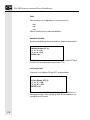
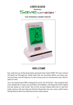
The front panel of the SOI–260 is a sealed unit comprised of a 4 x 20
character display window, 3 LED’s, and 25 tactile feedback keys. The
VFD version does not include the half moon brightness key and,
therefore has only 24 keys.
SOI 2SERIES
00
RUN
ALARM
MAIN
MENU
PREV
MENU
PREV
NEXT
F
Figure 2.1:
Y
1
2
3
N
4
5
6
EXP
7
8
9
/
.
0
CE
SOI-260 (LCD Display)
5
SOI-260 OPERATOR INTERFACE MODULE USER MANUAL
The 4 line by 20 character display uses either high contrast LCD technology with LED backlighting or Vacuum Fluorescent Display (VFD)
technology to provide high reliability and superior readability in all light
conditions. On LCD displays both the contrast and backlight levels are
keypad adjustable. You can only adjust brightness on VFD displays.
The keypad is separated by color into easily identified groups or functions. In addition, each key has a raised perimeter to provide tactile
feedback which provides a positive response even if the hand is gloved.
A RUN LED in the upper left corner of the operator interface indicates
proper operation of the onboard microprocessor. A red LED in the
upper right corner indicates an ALARM condition. A yellow LED in
the upper right corner of the F (Function) key illuminates when the
function mode is activated.
Storage of the PLC driver (communications protocol), configuration
information, and user-programmed screens are maintained in 8K or
40K of nonvolatile memory. The operator interface containing 8K of
onboard memory provides storage for approximately 50 user-programmed screens. The operator interface containing 40K of onboard
memory provides storage for approximately 240 user programmed
screens.
6
CHAPTER 2: HARDWARE
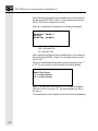
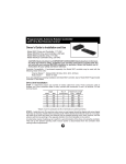
SOI–260 Functional Diagram
The diagram below provides a functional block diagram of the SOI–
260.
DISPLAY
4 x 20 Line
LCD or VFD
UART
RAM
Selectable
RS-485/422
or RS-232C
Interface
8k, 40K
Nonvolatile
Memory
SOI-260
Microprocessor
SOI-260
Comm
Port
Dipswitch
SW1
UART
RS-232C
Interface
Keypad
SOI-260
Printer
Port
Power Supply
Figure 2.2
5VD
Optional
SOI-260 Functional Block Diagram
Installing the SOI–260
Installing the SOI–260 is a three-step process:
•
Mounting
•
Power and communications connections
•
Establishing communications
7
SOI-260 OPERATOR INTERFACE MODULE USER MANUAL
Mounting the SOI–260: Environmental Considerations
The SOI–260 is rated for an operating temperature range of 32 to 113
°F (0 to 45 °C) for the LCD version and 32 to 140 °F (0 to 60 °C) for
the VFD version. The storage temperature range is -4 to 185 °F (-20 to
85 °C). The humidity rating is 5 to 95% relative humidity
(noncondensing). The operator interface is rated for NEMA Type 4
environments (indoor use only). The SOI-260S versions of the SOI–
260 are rated for NEMA Type 4X environments.
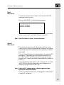
Installation
Select a suitable location for mounting the SOI–260. The SOI–260 is
intended to be flush mounted on the front of a control cabinet within
the environmental conditions stated above.
Using the template provided in Appendix C, mark the location of the
six mounting holes which secure the SOI–260 on your panel.
Mount the SOI–260. A neoprene gasket and a package of #6 - 32 UNC
nuts are provided. Tighten nuts to 4 inch-pounds.
1.8 in.*
(45.7 mm)
6.5 in.
(165.5 mm)
MAIN
MENU
8.5 in.
(216 mm)
PREV
MENU
PRE
NEX
F
7.6 in.
(193 mm)
Y
1
2
3
N
4
5
6
EX
7
8
9
/
.
0
C
* With Modbus
Plus, the depth
is 2.1 in.
(53.3 mm)
8
5.5 in.
(140 mm)
Figure 2.3
SOI-260 Dimensions
CHAPTER 2: HARDWARE
Power Connections
Before attempting to wire the SOI–260 ensure all power has been
removed from the power source.
The SOI–260 is available in two voltage ranges. Be certain that the
voltage available for your application matches the rating of the SOI–
260. The wrong voltage may damage the SOI–260.
!
ATTENTION: Verify that power is disconnected
from the power source before wiring the SOI–260.
High voltage can cause injury or death.
Wiring Recommendations
Careful wire routing helps cut down on electrical noise. Route incoming
power to the SOI–260 on a path separate from the communications
cables. Do not run signal wiring and power wiring in the same conduit.
Where power and communications lines must cross, their intersections
should be perpendicular. Communications lines can be installed in the
same conduit as low level DC I/O (less than 10 volts) lines.
All communications lines should be shielded. The shield should only be
connected to ground at the transmitting device.
Note: To prevent damage to the power terminals, make sure the power wiring
is not too tight (strained).
Grounding Recommendations
Grounding is an important safety measure in electrical installations.
Grounding also helps eliminate the effects of noise due to electromagnetic interference (EMI).
An authoritative source on grounding requirements is the National
Electrical Code published by the National Fire Protection Association of
Boston, Massachusetts. Article 250 of the Code describes the types and
sizes of wire conductors and safe methods of grounding electrical equipment and components.
Power connections for the 15 - 23 VAC or 20 - 30 VDC (AC1) and 85
- 265 VAC or 110 - 300 VDC (AC2) are provided below.
9
SOI-260 OPERATOR INTERFACE MODULE USER MANUAL
AC1 Version Power Supply
15-23 VAC 47-440Hz
20-30 VDC
800mA max.
GND
~—
~+
NEU
HOT
REPLACEMENT FUSE
EUROPEAN
1A TYPE GMD
U.S.A.
1A TYPE MDL
F2
AC2 Version Power Supply
85-265 VAC 47-440Hz
110-300 VDC
300 mA max.
GND
Figure 2.4
~—
~+
NEU
HOT
REPLACEMENT FUSE
EUROPEAN
500mA TYPE GMD
U.S.A.
1/2A TYPE MDL
F1
F2
AC1 and AC2 Power Supply Connections
Establishing Communications
The SOI–260 requires connections for communications to:
•
IBM PC or 100% compatible computer
•
Programmable Controller (PLC)
•
RS-232C serial printer (optional)
Connecting to a Computer
To connect the SOI–260 communication port to the computer serial
communications port, they must both use the same type signals (RS232C or RS-485) for the communication to be compatible and operational. This communication is required to download or upload a program file.
To establish communication between the SOI-260 RS-232 communication port and your computer, the SOI-260 must be selected for RS-232
communications and a RS-232 cable is required.
Note: See Chapter 4 for cabling and connection information.
10
CHAPTER 2: HARDWARE
To establish communication between the SOI–260 RS-485 communications port and your computer, one of the following is required:
•
An RS-485 serial port (COM1 or COM2) is installed in your
computer, and the appropriate cabling connects the SOI–260
RS-232C printer port to your computer RS-232C by setting
DIP switch SW-1-2 OFF.
or
•
An RS-232C serial port (COM1 or COM2) is installed in your
computer, and an optional SOI–260 RS-232C printer port with
the appropriate cabling connects the SOI–260 RS-232C printer
port to your computer RS-232C serial port. The printer port
must be enabled for successful operation.
Note: See Chapter 4 for cabling and connection information.
Connecting to a Printer
The optional RS-232C printer port for the SOI–260 connects to a
matching RS-232C serial printer and allows printing of preprogrammed
Printer Forms. You can configure the SOI–260 printer port for specific
baud rate, data bit, and parity settings. These communication parameters must match that of the connected printer or data will not be
correctly received by the printer.
The SOI–260 Printer Port option is RS-232C format with a standard
IBM nine pin “D” style connector.
Note: See Chapter 4 for cabling and connection information.
DIP Switch 1 (SW1)
DIP switch 1 settings enable or disable certain functions on the SOI–
260. The DIP switch is located under a removable plastic cover on the
upper back of the enclosure.
To access the DIP switch, remove the plastic cover from the upper back
of the SOI–260.
To select the appropriate settings for the application, set the switch
rocker up or down. Move the switch to the closed (ON) position to
enable a setting or to the open (OFF) position to disable a setting.
When you have set the DIP switches, replace the plastic cover.
11
SOI-260 OPERATOR INTERFACE MODULE USER MANUAL
The DIP switch (SW1) supplied as the standard configuration is defined
as:
DIP Switch
Function
Factory Setting
SW1-1
Upload/Download Enable
On
SW1-2
Communication Port Selection
On
SW1-3
Master Security Enable
Off
SW1-4
Function Key Enable
On
SW1-5
Terminal Mode Enable
Off
SW1-6
COMM Upload/Download Enable
Off
Note: When you change some of the DIP switch settings you may need to reset
or repower the SOI–260 before the new setting will take effect. Changes
to DIP SW1-2 take effect immediately. To reset the SOI–260, remove
power for at least 15 seconds, or use the Function (F) and 4 key
sequence. See function key description for more information.
Figures 2.4, 2.5 and 2.6 illustrate typical switch settings for download/
upload, and PLC communications.
1
2
3
4
5
6
ON
ON
ON
ON
SW-1
OFF
OFF
Figure 2.4
Typical Download/Upload Switch Settings
1
SW-1 OFF
2
3
4
ON ON ON
Figure 2.5
2
SW-1 OFF OFF
12
6
OFF OFF
Typical Switch Settings for Communicating with a PLC using the RS485/422 Connection
1
Figure 2.6
5
3
4
ON ON
5
6
OFF OFF
Typical Switch Setting for Communicating with a PLC using the RS232 Connection
CHAPTER 2: HARDWARE
SW1-1 Upload/Download Enable
The ON position disables communications between the SOI–260 and
the PLC. All keypad activity is also disabled. In this mode, application
files can be uploaded/downloaded between the SOI–260 and a personal
computer. The OFF position enables communication between the
SOI–260 and PLC. The SOI–260 resets each time SW1-1 is changed.
SW1-2 Communication Port Selection
Selects the communication standard for the communications port.
When SW1-2 is ON, the port is configured for RS-485 operation.
When OFF the port is configured for RS-232. Changes to SW1-2 take
effect immediately.
SW1-3 Master Security Enable
When this switch is ON, the master code is enabled and allows any
security code to be accessed or modified. When OFF, the master code
does not allow other security codes to be modified. However, the master
code allows access to the security screens. Changes to SW1-3 take effect
immediately.
SW1-4 Function Key Enable
When SW1-4 is ON, the front panel function key is enabled. All items
associated with the function key are accessible from the keypad. The
OFF position disables the function key. Changes to SW1-4 take effect
immediately.
SW1-5 Terminal Mode Enable
When SW1-5 in ON, the SOI–260 operates in terminal mode displaying all ASCII data received from the communications port and transmitting text from any keys pressed. When OFF terminal mode is
disabled an the SOI–260 operates normally.
Note: Manually reset the SOI–260 after enabling or disabling terminal mode.
SW1-6 Comm Upload/Download Enable
40K Versions (with Printer Port)
When this switch is ON it enables uploads and downloads through the
communication port.
13
SOI-260 OPERATOR INTERFACE MODULE USER MANUAL
When the switch is OFF the communication port may not be used to
upload or download using the SOI–260 programming software. You
may only upload or download using the printer port. This allows you to
maintain a network connection at the communication port.
The SOI–260 should manually be reset after changing the setting on
this switch.
Important: If the SOI–260 is connected for RS-232 communication to the PLC and
you desire to download an application program using the printer port,
the following must be performed prior to downloading:
•
Set DIP switch 1-6 to OFF.
•
Set DIP switch 1-1 to ON (program download enable).
•
Set Dip switch 1-2 to ON (RS-485).
•
Download the application program.
When you have completed downloading the application program,
perform the following:
•
Place DIP switch 1-1 to the run mode (OFF).
•
Place DIP switch 1-2 to the RS-232 (OFF).
•
Place DIP switch 1-6 to ON.
8K Versions (Without Printer Port)
ON or OFF - The SOI–260 allows uploading or downloading through
the communication port when the switch either is ON or OFF.
Important: If switch SW1-6 is ON AND you are connected to a network through
the communication port, improper SOI–260 operation may occur.
Indicator LEDs
Three LED indicators are located on the front panel of the SOI–260.
When illuminated, these indicators provide a visual status of the RUN,
ALARM and FUNCTION key modes of the SOI–260:
Run LED (Green)
The RUN LED is located in the upper left corner of the front panel.
When illuminated, this LED provides an indication that the SOI–260 is
functioning correctly. This LED should always be illuminated during
SOI–260 operation.
14
CHAPTER 2: HARDWARE
Alarm LED (Red)
The ALARM LED is located in the upper right corner. This LED will
flash on and off to indicate that an alarm has been triggered. It will
continue to flash until all alarms have been acknowledged.
Function LED (Yellow)
The FUNCTION LED is located in the upper right corner of the gray
F (Function) key. This LED illuminates when a function key operation
is in progress. You initiate a function key operation by pressing the F
key when in normal operation.
The LED is extinguished when the Function mode is terminated or by
exiting the function key operation.
Note: DIP switch SW1-4 must be ON for the function key to operate.
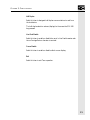
Keypad
The keys on the SOI–260 keypad are distinguished by their color-coded
operational typed or category. Each color grouping of keys denotes a
common type of operation which you may perform.
Key Color
Function
Green
Movement and operator response
Light Gray
Display and format control
White
Numeric Entry
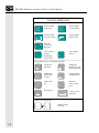
Figure 2.7 illustrates the keys and describes their basic functions.
15
SOI-260 OPERATOR INTERFACE MODULE USER MANUAL
SOI-260 QUICK REFERENCE GUIDE
Screen Movement / Operator Response Keys (Green)
MAIN
MENU
PREV
F
Y
Switches Display
to Main Menu
Switches Display
to Previous Screen
PREV
MENU
NEXT
Switches Display
to Previous Menu
Switches Display
to Next Screen
Accesses
Function Key
Operations
“YES” response.
Bit entry.
Acknowledge
Alarm screens.
N
“NO” response.
Bit entry.
Display Characteristics / Format Keys (Light Gray)
EXP
.
LED Contrast
Adjustment
LED Backlight
Adjustment or VFD
Intensity Adjustment
Exponent key
(Floating Point
formats)
Sign key (Positive
and Negative data)
/
Decimal Point
Key
CE
Clear Entry
(clears current
entry)
Backspace key
“Enters” current
data to PLC
Numeric Entry Keys (White)
0
Figure 2.7
16
9
SOI-260 Keypad
Numeric 0-9 Data
Entry Keys
CHAPTER 2: HARDWARE
Green Keys
The seven green keys located at the top of the SOI–260 control movement within a program. You can move from menu to menu using the
MAIN MENU and PREV MENU keys from screen to screen using the
PREV and NEXT keys. A description of these keys is provided below.
MAIN
MENU
MAIN MENU key*
The MAIN MENU key returns you to the main menu of the application program you are presently in whenever the key is pressed.
PREV
MENU
PREV MENU key*
(Previous Menu)
The PREV MENU key steps you back through menus. This is very
helpful when submenu screens occur extensively throughout a program.
By pressing the PREV MENU key enough times, you eventually will
return to the main menu.
* = Note: The PREV MENU and MAIN MENU keys operate in the same manner
in the event an ALARM condition has been detected. If the ALARM
LED is flashing, the green Y key must be pressed acknowledging the
ALARM condition before you are able to proceed to the main menu
using the MAIN MENU key.
PREV
PREV Key
(Previous)
The PREV key moves to the previous non-menu screen in any given
sequence of linked screens.
Note: Refer to SOI–SPS Software Programming Manual for more
information on linking screens.
NEXT
NEXT Key
The NEXT key moves to the next screen in any given sequence of
linked screens.
The yes and no keys are for operator responses, and the Enter key sends
data to the PLC.
17
SOI-260 OPERATOR INTERFACE MODULE USER MANUAL
Y
Y Key
(Yes)
The Y key enters a yes response or acknowledged when an alarm is
displayed. You can use the Y key to set the status of a bit at a data entry
screen. Also, when you are in P-A/D press this key to increment the
Address fields.
N
N key
(No)
The N key enters a no response or acknowledgment. You can also use
the N key to clear the status of a bit at a dat entry screen. Also, when
you are in P-A/D press this key to decrement the Address fields.
↵ Key
(Enter)
The enter key sends the entered data to the PLC processor. It does not
matter whether the data on the display is a default value or a value you
entered, the data is still sent to the processor.
CE
CE Key
(Clear Entry)
The CE key deletes an entire data entry.
For example, you might enter a five digit number and the first and third
digits were incorrect. By pressing the CE key the entire value would be
deleted, and you could enter a new value.
Once you press the ENTER key, the value entered is sent to the PLC
processor and cannot be deleted with the CLEAR ENTRY key.
F
18
F Key
(Function)
(Used to select PLC-specific features)
CHAPTER 2: HARDWARE
The F key sets special features and operating parameters of the SOI–
260. The F key is enabled or disabled for the PLC by setting DIP switch
SW 1-4. See the DIP switches section in this chapter for more information.
When you press the function key, the F LED illuminates, indicating the
SOI–260 is in the function mode. At this time, the function key menu
is displayed.
The MAIN MENU key aborts the function key and returns you to the
main menu regardless of the function key mode in progress.
The PREV MENU key allows you to move through the previous
selections until the function key menu is displayed, the F key terminates
the function mode and returns operation to the main menu.
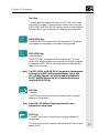
The function key menu appears as follows:
1
2
3
4
C-Port
P-Port
Clk/Cal
Reset
5
6
7
8
Special
Term
Test
Other
To select a menu item, press the number on the keypad corresponding
to the menu item number.
Each of these functions are described in Chapter 3: Function Keys.
Light Grey Keys
The eight light grey keys control the visual characteristics, numeric
format of the display, and access to the special features and operating
parameters mode.
Contrast Key
(Half Moon Symbol)
The contrast key adjusts the amount of contrast the display uses for
viewing purposes. Contrast is adjustable in four steps.
This key is useful for fine tuning the display in unique lighting, temperature, or viewing conditions.
Note: This key is only included with the liquid crystal display (LCD) model of
the SOI–260.
19
SOI-260 OPERATOR INTERFACE MODULE USER MANUAL
Brightness Key
(Sun Symbol)
The brightness key adjusts the amount of LED backlighting on LDC
displays, which is adjustable in 4 steps. This key also adjusts the character brightness on VFD displays in 4 steps.
Backlighting is useful if the ambient lighting conditions are not bright
enough to allow clear viewing of the display.
.
. Key
(Decimal Point)
The decimal point key enters a decimal point in data entry screens.
EXP
/
EXP Key
Pressing the EXP key sends the screen currently displayed on the SOI–
260 to a connected serial printer. When used with PLC’s supporting
floating point, this key also allows entry of exponential numbers. This
feature must be enabled via the function key menu as described in
Chapter 3.
+/- Key
(Change Sign)
The change sign key indicates negative or positive numeric values. The
key toggles an entry value between + (positive) and - (negative), and is
fully functional with all valid signed-entry data types.
‹— Key
(Backspace)
The backspace key moves the cursor back one position (character) at a
time, and deletes the character in the process.
20
9
White Keys
The ten white numeric keys control data entry.
CHAPTER 3: FUNCTION KEYS
Chapter 3: Function Key
This chapter describes the operations performed by the function key
menu. Each of the eight menu items listed below is described in detail.
1. C-Port (Communications Port)
2. P-Port (Printer Port)
3. CLK/CAL (Clock/Calendar)
4. Reset
5. Special
6. Term (Terminal)
7. Test
8. Other
C-Port (Communications Port)
Menu Item 1
This menu item sets the SOI-260 operating parameters of the communications port (RS-485/422 or RS-232C).
Normally all communications port parameters are set automatically
when you download an application program to the SOI-260. If you
need to make a change to these settings, you would do that here.
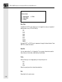
The C-Port function has an associated menu which appears as:
21
SOI-260 OPERATOR INTERFACE MODULE USER MANUAL
Select item:
1 Baud Rate
2 Data Bits
3 Parity
4 Exit
Baud Rate
The BAUD RATE menu allows you to change the comm port speed of
data transfer to any of the following:
300
1200
2400
4800
9600
19200
38400
Use the NEXT or PREV key to sequence through the baud values. Press
ENTER to select the value.
Data Bits
You can select either 7 or 8 data bits. The number of data bits used for
the printer port normally is defined by the software.
Parity
Parity allows you to change parity on the printer port to:
even
odd
none
Select the parity similar to baud rate selection .
Exit
Steps back to the main menu.
22
CHAPTER 3: FUNCTION KEYS
P-Port (Printer Port)
Menu Item 2
This menu item allows parameters of the RS-232 printer port to be set
manually. Normally, these parameters are set from the programming
software when an application program is downloaded to the SOI-260.
The P-PORT menu is shown below:
1
2
3
4
Baud Rate
Data Bits
Parity
Hndshk
5 L/Feed
6 Penabl
7 Exit
Baud Rate
The BAUD RATE menu allows you to change the printer port speed to
any of the following:
300
1200
2400
4800
9600
19200
38400
Use the NEXT or PREV key to sequence through the baud values. Press
ENTER to select the value.
Data Bits
You can select either 7 or 8 data bits. The number of data bits used for
the printer port normally is defined by the software.
23
SOI-260 OPERATOR INTERFACE MODULE USER MANUAL
Parity
Parity allows you to change parity on the printer port to:
even
odd
none
Select the parity similar to baud rate selection.
Handshake (Hndshk)
Hardware handshaking choices are enable or disable as shown below:
HNDSHK Enable OFF (0)
“1” or “Y” = ON
“0” or “N” = OFF
ENTER = NC
Handshaking is a request to send a communications signal (RTS and
notification that a transmission may be sent (CTS).
Line Feed (L/Feed)
Choices for Line Feed are ON and OFF as shown below:
L/Feed Enable OFF (0)
“1” or “Y” = ON
“0” or “N” = OFF
ENTER = NC
When enabled the SOI-260 sends a line feed (LF), in addition to a
carriage return after a form has been printed. When disabled only a
carriage return will be sent.
24
CHAPTER 3: FUNCTION KEYS
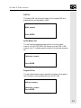
Printer Port (Penabl)
The printer can be selected as ON or OFF as shown below:
PORT Enable ON (1)
“1” or “Y” = ON
“0” or “N” = OFF
ENTER = NC
Note: To upload or download using the printer port, the printer port must be
enabled.
Exit
Exit steps back to the function key menu.
CLK/CAL (Clock/Calendar)
Menu Item 3
This function key menu item sets and displays the internal real time
clock of the SOI-260 (available on SOI-260-x40 units only).
The CLK/CAL option provides time and date information for SOI-260
operations. The time and date may also be inserted into operator screens
and printer forms or downloaded to the PLC using the Time Synchronization Command. Refer to the SOI-260 Programming Manual for
more information concerning time synchronization.
The internal real time clock is accurate to +/- 1 minute per month @ 25° C.
When you select the CLK/CAL item, the following is displayed:
ENTER DATE MM.DD.YY
MM = Month
DD = Day of Month
YY = Year
25
SOI-260 OPERATOR INTERFACE MODULE USER MANUAL
Enter new values with decimal points between each of the numbers for
the date and press ENTER to load. The new values are then stored in
the SOI-260 (but not loaded into the clock).
When you have entered the new values, the following is displayed:
ENTER DATE MM.DD.YY
XX.XX.XX
ENTER TIME HH.MM.SS
HH = Hour (0-23 or 1-12)
MM = Minutes (0-59)
SS = Seconds (0-59)
Enter new values with decimal points between each of the numbers for
the time and press ENTER to load. The new values are then stored in
the SOI-260.
When you have entered the new values, you are prompted to enter “Y”
or “N” for your choice of time format with the following display:
Select Time Format
“Y” = 24 Hour Format
“N” = 12 Hour Format
Enter “Y” to select the 24 hour format, or “N” to select the standard
(AM/PM) format. If you enter “N”, you are prompted for an AM or
PM setting.
The new date and time are loaded into the internal clock and displayed.
26
CHAPTER 3: FUNCTION KEYS
Reset
Menu Item 4
This function key menu item initiates a “soft” reset of the SOI-260,
restarting all internal circuitry.
When you select RESET, the following screen appears:
Press “Y” to Reset
Press “N” to Abort
If you enter Y, the SOI-260 resets. This feature is useful for activating
the Term mode if the Term Mode DIP switch is set to ON.
Note: See DIP Switches in Chapter 2 for more information.
Special
Menu Item 5
This function key menu item will allow access to the Point Access/
Display function. A security access code can be defined in the programming software and will be implemented once the application has been
downloaded.
The Point Access/Display function allows access to all unrestricted PLC
data registers. These registers can be displayed and modified at the
SOI-260. The NEXT and PREV keys scroll forward and backward
through the PLC register types. Select a desired register by pressing the
Enter key.
If you have specified a valid register, it will be displayed. If it is invalid,
the SOI-260 will display a communication error message which is
cleared by pressing the MAIN MENU key.
Note: Refer to the PLC reference section on the data registers and types
supported for each protocol selection.
The PA/D is useful when starting up or debugging SOI-260 programs
or regular PLC operations.
27
SOI-260 OPERATOR INTERFACE MODULE USER MANUAL
!
ATTENTION: The P-A/D should be restricted only
to authorized personnel. It is possible to change PLC
data which may alter the correct operation of the
SOI-260.
When a P-A/D screen is displayed, the PREV MENU key will return
you to the Special Menu and the MAIN MENU key will exit the
function key mode and return you to online operation.
Term (Terminal Mode)
Menu Item 6
This function key menu item allows you to set communication and
display parameters for the Terminal mode.
The Terminal mode disables execution of the downloaded program and
enables the SOI-260 to function as a terminal device. In the Terminal
mode, the SOI-260 displays any ASCII data received through the
communications port. The ASCII codes associated with the keys on the
SOI-260 keypad are transmitted through the communications port
when a key is pressed.
Note: Refer to Appendix B, Terminal Mode, for the ASCII codes displayed
and mapped to the keypad.
To activate the Term mode, set DIP switch SW 1-5 to the closed (ON)
position and reset the SOI-260. The display will then blank and be
ready to receive incoming ASCII data.
When you select TERM, the following screen appears:
1
2
3
4
28
Half Duplex
Line Feed Enable
Cursor Enable
Exit
CHAPTER 3: FUNCTION KEYS
Half Duplex
Select this item to designate half duplex communications to and from
the host device.
The half duplex selection echoes (displays) to the screen the SOI-260
keys pressed.
Line Feed Enable
Select this item to enable or disable the use of a Line Feed character each
time a Carriage Return character is received.
Cursor Enable
Select this item to enable or disable a block cursor display.
Exit
Select this item to exit Term operation.
29
SOI-260 OPERATOR INTERFACE MODULE USER MANUAL
Test
Menu Item 7
The Test menu has selections which allow you to perform diagnostic
testing. At the completion of a diagnostic testing. At the completion of a
diagnostic test, all SOI-260 configurations are restored to pretest settings. When you select the test function from the function key menu,
the following screen appears:
SOI-260 Diagnostic
NEXT to Select Text
Enter to Initiate
Reset DUT
Press the NEXT and PREV keys to toggle through the available test
selections. When the test you want is displayed, press ENTER. The
available selections are:
•
•
•
•
•
•
•
•
•
•
•
•
Reset DUT
Dipswitch
Display Test
Keyboard
Comm Port
Printer Port
Display Control
RAM Test
System Memory
Program File
Clock/Calendar
TXEN & Alarm
Reset DUT
Pressing the Enter key with Reset DUT displayed performs a soft reset.
It is the only way to terminate the test menu.
30
CHAPTER 3: FUNCTION KEYS
Dipswitch Test
The SOI-260 displays the current DIP switch positions in binary
format. The OFF (open) position displays as logic 0 and the ON
(closed) position displays as logic 1. Switch positions 1 through 6 are
shown from left to right.
SW-1
DIP Switch:
SW-6
0111100
Display Test
The Display Test verifies that each display pixel is operating properly.
All pixel turn on, then off, then alternate a checkerboard pattern (positive and negative) until a key is pressed.
Keyboard Test
This test prompts you to press each key on the keypad in a sequential
manner to test keypad operation.
Comm Port Test
This test transmits a message our the communications port. If a
loopback connector is attached as shown in figure 3.1, the message will
be received by the same port and will continuously display until a key is
pressed. The test operates in both RS-232 and RS-485 settings if the
correct loopback connector is attached.
The message displayed during the test is a moving display as shown
below.
SOI-260 Self Looping Serial Test
ABCDEFGHIJKLMNOPQRSTUVWXYZ
1234567890
31
SOI-260 OPERATOR INTERFACE MODULE USER MANUAL
Printer Port Test
This test transmits a message out the Printer Port. If a loopback connector is attached (as shown in figure 3.1), the message will be received by
the same port and continuously displayed on the screen until a key is
pressed. This test will not run if the port is disabled.
SOI-260 RS-232C Loopback Connector
Communications or Printer Port
(9 Pin Female Printer Port,
9 Pin Male Communications Port)
1
2
3
4
5
6
7
8
9
SOI-260 RS-485/422
Loopback Connector
Communications Port
9 Pin Male
1
2
3
4
5
6
7
8
9
Data In
Data Out
RTS (out)
CTS (in)
= Female Connector
Data Out Data Out +
Data In Data In +
= Male Connector
Display Control
This test adjusts the LCD display to each of the 4 contrast and brightness setting (only 2 for the VFD display). During the brightness test,
the following screen appears:
***************************************************
DISPLAY BRIGHTNESS
TEST
***************************************************
The Contrast test immediately follows the Brightness test and shows the
following screen:
***************************************************
DISPLAY CONTRAST
TEST
***************************************************
VFD version of the SOI-260 does not include the Contrast test.
32
CHAPTER 3: FUNCTION KEYS
RAM Test
The System RAM test checks the integrity of the internal RAM and
displays whether the test passed or failed.
RAM : passed
Press ENTER
System Memory Test
This test checks the operating system portion of the non-volatile
memory in the SOI-260 (64K in 8K memory units and 128K in 40K
memory units). The display shows the results of the checksum as pass or
fail.
Checksum : passed
Press ENTER
Program File Test
This test checks the user memory size and the checksum of the application file stored in the nonvolatile memory of the SOI-260.
40K user memory
Checksum : passed
Press ENTER
33
SOI-260 OPERATOR INTERFACE MODULE USER MANUAL
Clock/Cal Test
This test displays the current date and time in the SOI-260. The display
updates the time until the ENTER key is pressed. This test is only
supported by units that have a real time clock.
TIME XX:XX:XX PM
DATE Day Mon XX XX
Press ENTER
TXEN and Alarm Test
This test verifies the operation of the transmit enable line on the Communications Port when set for RS-485 and also toggles the Alarm LED
to verify its operation. The test toggles the TXEN line and alarm LED
at a rate of approximately 1 cycle per second until you press the ENTER
key.
Toggling TXEN line
Astable Alarm LED
Press ENTER
The figure below shows how to connect an LED to the transmit line.
The LED will flash approximately once every second during the TXEN
test.
SOI-260 RS-485/422
Communications Port
9 Pin Male
1
2
3
4
5
6
7
8
9
Data Out Data Out +
Data In Data In +
= Male Connector
34
750 Ω
CHAPTER 3: FUNCTION KEYS
Other
Menu Item 8
This menu item will contain miscellaneous functions that will influence
the operation of the SOI-260. This menu contains the following functions:
1
2
3
4
Simulate
BL / INT
Contrast
Prn Scrn
5 Mastr C
6 Scale E
7 Exit
Simulate
Simulate protocol selections are enable or disable.
When simulate is enabled, communication between the SOI-260 and
PLC is halted. In this mode the SOI-260 will simulate communication
with the PLC. All expected data is returned as 0 (zeros). When disabled,
the brightness will remain at the current setting and can not be changed
with the front panel keys. The setting will be maintained after power is
cycled to the SOI-260.
Simulate mode is a great tool for dry-running programs to ensure proper
operation and screen flow and layout.
BL/INT (Backlighting / Intensity)
When brightness is enabled, you can adjust the display backlighting for
LCD versions, or character intensity for VFD versions. When disabled,
the brightness will remain at the current setting and cannot be changed
with the front panel keys. The setting will be maintained after power is
cycled to the SOI-260.
Contrast (LCD version only)
When enabled on the LCD version, you may adjust the contrast of the
character display. When disabled, the contrast will remain at the current
setting and cannot be changed with the front panel keys. The setting
will be maintained after power is cycled to the SOI-260.
35
SOI-260 OPERATOR INTERFACE MODULE USER MANUAL
Prn Scrn (Print Screen)
When print screen is enabled, the current display is captured and sent to
the Printer Port whenever the EXP key on the front panel is pressed.
The display is also printed if the EXP key is pressed for entering floating
point data. When disabled, print screen is disabled and the EXP key can
only be used for entering floating point data.
Mastr C (Master Security Code)
The master security code function allows you to edit the master security
code of the SOI-260. The code must be 8 digits in length. If less than 8
digits are entered, the code is padded with zeros. For example, a code
defined as “1234” will be used in the SOI-260 “12340000”.
When selected, the following screen is displayed.
Enter Current Master
Code: _
The current master code needs to be entered for verification. If the
wrong code is entered, the SOI-260 display will indicate the wrong code
has been entered and exit to the other menu. When the correct code is
entered, the SOI-260 will prompt you to enter a new code as shown
below.
Enter New Master
Code: _
An entry of all zeros (0) as the new master code will allow you to modify
the code without the need to enter the current code. In this case the
SOI-260 will only prompt you to “Enter New Master Code”. If the
master code is defined as all 9’s the SOI-260 will not allow you to
modify the master security code. Only the PLC software should be used
to set the master code as all 9’s.
36
CHAPTER 3: FUNCTION KEYS
Since wild cards (?) are used with the security codes, these codes have
precedence over the master code. For example, security code = 12??????
and master code = 12340000. If the master code is entered on the SOI260 it will be interpreted as the security code. You are responsible for
creating a different master code from any security code which may have
wild cards.
Scale E (Scale Enable)
Scale E enables or disables SOI-260 auto-scaling. When enabled,
numeric values from the PLC will be scaled to engineering units. When
disabled, numeric values will not be scaled.
Exit
Exit allows you to exit the Other Menu and returns you to the main
Function Key Menu.
37
SOI-260 OPERATOR INTERFACE MODULE USER MANUAL
38
CHAPTER 4: COMMUNICATIONS
Chapter 4: Communications
This chapter describes the cabling and configuration needed to use the
SOI-260 communications port and the optional printer port.
Use these ports to upload and download program files to and from a
computer. Also, use these ports for communications with a PLC,
printer, or other serial device.
Note: Some versions of the SOI-260 Operator Interface are equipped with a 9pin ModBus Plus Port. Please refer to Spectrum Controls Publication
#0300062-xx, “Modicon Reference,” for information regarding the
ModBus Plus Communications Port.
Using the Communications Port
All communications occur through a 9-pin connector on the bottom of
the SOI-260. The connector can be configured as either an RS-232 or
RS-485 port by setting the SOI-260’s DIP switches. The DIP switches
are described in Chapter 2: Hardware, under Installing the SOI-260.
RS-232
1
2
6
PIN#
1
2
3
4
5
6
7
8
9
3
7
4
8
RS-485
1
5
Signal Name
Not Used
Receive Data (RD)
Transmit Data (TD)
Not Used
Signal Ground
Not Used
Not Used
Not Used
Shield
2
6
9
PIN#
1
2
3
4
5
6
7
8
9
3
7
4
8
5
9
Signal Name
Data Out Data Out +
Data In Data In +
Signal Ground
Transmit Enable
Not Used
Signal Ground
Shield
39
SOI-260 OPERATOR INTERFACE MODULE USER MANUAL
SOI-260 Upload/Download Cabling
Figure 4.1 shows the cabling between the SOI-260 communications
port and the serial port of a personal computer (this will allow you to
upload or download SOI-260 program files). The illustration below
indicates pinouts for both 9-pin and 25-pin connections. Spectrum
Controls offers a RS232C 9-pin to RS232C 25-pin cable for purchase
(catalog number SCC-3).
SOI-260 RS232C
Communications Port
9 pin:
9 pin:
Data In
Data Out
Signal Ground
Data Out
Signal Ground
1
2
3
4
5
6
7
8
9
1
2
3
4
5
6
7
8
9
9 pin:
Data In
Computer Serial Port (RS232)
(COM1, COM2)
Data In
Data Out
Signal Ground
25 pin:
1
2
3
4
5
6
7
8
9
Male Connector
1
2
3
4
5
6
7
8
9
Data Out
Data In
Signal Ground
Female Connector
Figure 4.1
SOI-260 to PLC Cabling.
The communication cable used to connect an SOI-260 to a specific
PLC is unique to the PLC that it is connected to. Refer to the PLC
Reference Section for SOI-260 to PLC communication cable wiring
diagrams.
40
CHAPTER 4: COMMUNICATIONS
Using the Printer Port
Figure 4.2 shows the cabling for the optional RS-232C Printer Port of
the SOI-260. Use this port to send data to a printer or other serial
device such as a large display. The illustration below indicates pin-outs
for both 9-pin and 25-pin connections.
SOI-260 RS232C
Printer Port
9 pin:
Data Out
Signal Ground
Request to Send
Clear to Send
9 pin:
Signal Ground
Request to Send
Clear to Send
1
2
3
4
5
6
7
8
9
1
2
3
4
5
6
7
8
9
9 pin:
Data Out
RS-232 Printer or
Other Serial Device
Data In
Signal Ground
Requesst to Send
Clear to Send
25 pin:
1
2
3
4
5
6
7
8
9
Male Connector
1
2
3
4
5
6
7
8
9
Data In
Request to Send
Clear to Send
Signal Ground
Female Connector
Figure 4.2
41
SOI-260 OPERATOR INTERFACE MODULE USER MANUAL
SOI-260 to Computer connections
Figure 4.3 illustrates the typical connection method used when up/
downloading the SOI-260 program.
SOI-260
Programming Terminal
Cable
(Catalog No. SCC-3)
Figure 4.3
Note: The SCC-3 cable may be purchased from Spectrum Controls, Inc.
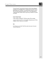
SOI-260 to PLC Connections
Figures 4.4 through 4.8 illustrate the connections between the SOI-260
and the PLC. Connections to the PLC communication port, connection via communication modules, as well as connection to a Printer are
shown as examples below.
Figure 4.4 illustrates the connections between the SOI-260 and a PLC
communication port.
42
CHAPTER 4: COMMUNICATIONS
SOI-260 / PLC Direct Connect
PLC
Input
Output
PLC
Programming
Port
SOI-260
RS 485/RS232
Comm. Port
PLC Comm. Cable
• SOI-260 Comms to PLC
• SOI-260 & PLC are connected to the same power source and
ground potential
Figure 4.4
Figure 4.5 illustrates the connections between the SOI-260 and PLC via
a communication module.
SOI-260 Connection to a PLC Communication Module
SOI-260
PLC
Input
Output
PLC COMM
PLC
Comm
Module
SOI-260
RS 485/RS232
Comm. Port
PLC Comm. Cable
• SOI-260 Comms to PLC Comm Module
• SOI-260 & PLC with PLC Comm Module are separated by a
distance specified by the PLC Manufacturer
Figure 4.5
43
SOI-260 OPERATOR INTERFACE MODULE USER MANUAL
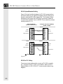
Figure 4.6 illustrates the connections between the SOI-260 and PLC via
network modules. (network modules residing in PLC racks)
SOI-260 Connection to a PLC Network Module
PLC
Input
Output
Network
PLC
Network
Module
SOI-260
RS 485/RS232
Comm. Port
PLC Network Comm. Cable
• SOI-260 Comms to PLC Network Module
• SOI-260 & PLC Network Module are separated by a distance
specified by the PLC Manufacturer
Figure 4.6
Note: The SOI-260 does not support all network communications. Refer to the
PLC reference section and the PLC manufacturers operations manual
for details on the specific PLC.
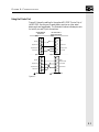
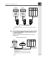
Figure 4.7 illustrates the connections between the SOI-260 and PLC via
network modules. (network modules external to the PLC)
44
CHAPTER 4: COMMUNICATIONS
SOI-260
SOI-260
RS-485/
RS-232
Comm. Port
PLC
SOI-260
SOI-260
RS-485/
RS-232
Comm. Port
Input
Output
PLC
Programming
Port
PLC Comm. Cable
• SOI-260 Comms to PLC
• SOI-260 & PLC are connected to the same power source and ground potential
Figure 4.7
Note: The SOI-260 does not support all network communications. Refer to the
PLC reference section and the PLC manufacturers operations manual
for details on the specific PLC.
Figure 4.8 illustrates the connections between the SOI-260 and a
standard printer.
SOI-260 / PLC Direct Connect
PLC
SOI-260
Input
Output
Printer
RS 485/RS232
Comm. Port
RS232
Printer Port
Printer Comm.
Cable
PLC
Programming Port or
Communications Port
PLC Comm. Cable
• SOI-260 Comms to PLC
• SOI-260 & PLC are connected to the same power source and
ground potential
• Please refer to the Printer Port Cabling section for wiring diagram.
For printer details, refer to the printer manufacturer's operations
manual.
Figure 4.8
45
SOI-260 OPERATOR INTERFACE MODULE USER MANUAL
46
CHAPTER 5: TROUBLESHOOTING
Chapter 5: Troubleshooting
The following troubleshooting information pertains to general conditions of the SOI-260 and its operations. This information is presented
as potential symptoms and describes possible solutions.
The SOI-260 will display a variety of screens or error codes upon
detection of extraordinary conditions. The information displayed may
help in isolating problems. The SOI-260 also contains a Self Test mode
that performs a full functional test of the unit.
Note: The Self Test mode operation is described in Chapter 3: Function Keys,
under Test Menu Item 7.
Important: The symptoms and descriptions described below encompass a wide range
of both hardware problems and indications of operator entry errors. For
problems relating to the SOI-260 and PLC operations, refer to the
applicable SOI and specific PLC software manuals.
47
SOI-260 OPERATOR INTERFACE MODULE USER MANUAL
PLC Error Conditions
The following provides a list of SOI-260 displays for error conditions of
the PLC. Possible corrective actions is also provided.
Checksum failed
ROM checksum is incorrect. Possible defective ROM.
Action
Reset the SOI-260. If problem still exists, reload the operating system
through the software. If problem persists, return SOI-260 for repair.
RAM fail
RAM memory failed write or read test.
Action
Reset the SOI-260. If problem persists, return SOI-260 for repair.
Error Conditions
Check-sum: nnnn (.CFG file)
Check-sum: nnnn (SOI-260)
CFG File is invalid
Application file checksum is incorrect. Possible bad application file.
Action
Download the application program (.CFG) file again. If problem
persists, return SOI-260 for repair.
Watch Dog Fault
Push key to continue
Watch dog timer not within specifications.
Action
Return SOI-260 for repair.
48
CHAPTER 5: TROUBLESHOOTING
Watch Dog Fault Push key to reset
Watch dog timer timed out or pass bits not set.
Action
Return SOI-260 for repair.
Establishing Comm
Attempting to communicate to PLC.
Action
No action is required. This is the normal screen when initiating communications with the PLC.
PLC not found
This display is presented after a 2 second interval of attempting to
establish communications with the PLC.
Action
Check cabling and communications parameters to verify the PLC
matches those of the SOI-260.
PLC not Responding
PLACE PLC ON LINE
Communication failure to respond to repeated attempts after initial
communications were achieved.
Action
Press any key. Check SOI-260 to PLC cabling. Check PLC operating
conditions.
COMM ERROR, Press “Y”
Communication with the PLC was lost after XX attempts.
Action
Check SOI-260 to PLC cabling. Check PLC operating conditions.
49
SOI-260 OPERATOR INTERFACE MODULE USER MANUAL
Comm ERROR PRESS Y
PLC error code: nnn
Communication error code (nnn). Received a PLC error code.
Action
Refer to the error code information in the specific PLC hardware or
software manual.
Attempt made to
”call” and invalid or
unprogrammed screen
Illegal or unprogrammed screen type detected (.CFG) file and download. Check linking.
NOT PROGRAMMABLE
Master code is 99999999 and is not programmable by the user.
Action
Download new and valid master security code using the applicable
software.
INVALID SECURITY
CODE ACCESS DENIED
“Y” TO CONTINUE
Master code or 3 screen codes did not match
Action
Either an incorrect master security code or a code that did not match
the 3 programmed codes was entered. Ensure the security code you are
entering is correct and is entered properly.
50
CHAPTER 5: TROUBLESHOOTING
Printer not Ready
Press “Y” to Abort
Press “N” to Resume
Printer offline for more than 2 seconds.
Action
This may occur if handshaking is enabled. Place printer on-line.
Self Test Failure
In the self test mode the transmitted character did not match the received character. The transmitted character and the received character
also appear on the display.
Action
Verify that the loopback connector is connected to the communication
and/or printer ports. If problem persists, return SOI-260 for repair.
** Input Error **
Low
High
n.nn
n.nnn
“Y” to Continue
OR
** Input Error **
Low
n.nnnnn
High
n.nnnnn
“Y” to Continue
The data entered is not within the programmed limits. The low and
high limits, as programmed, are displayed.
Action
Verify the displayed limits are within programmed limits. The low and
high limits as programmed, are displayed.
NaN (Not a number)
The floating point data is not a correct floating point data format.
Action
Check the data in the PLC location and verify the data for correct
Floating Point format.
51
SOI-260 OPERATOR INTERFACE MODULE USER MANUAL
INF
The floating point data has been received as a +/- infinity type.
Action
Check the data in the PLC location and verify the data for correct
Floating Point format.
No relation
Indication that an invalid floating point compare was done.
Action
Verify that the PLC location allows floating point formats.
READONL
The PLC location is not configured for a write function (P-A/D function).
Action
Verify that the PLC location being accessed by the P-A/D allows write
functions.
SOI-260 Programming Software / SOI-260
Version
Mismatch
* SOI-260 LOCKED *
An incorrect unlock code sent by SOI-SPS programming software.
Wrong version of SOI-260 programming software.
Action
Verify that the version of SOI-260 programming software is compatible
for the PLC type supported by the SOI-260, and reload the operating
system as described in Chapter 2.
52
CHAPTER 5: TROUBLESHOOTING
(Any unusual characters being displayed)
Check the screen linkage in your application and reload the operating
system as required.
or
The baud rate is incorrect. Ensure the baud rates between the SOI-260
and the PLC are the same.
53
SOI-260 OPERATOR INTERFACE MODULE USER MANUAL
54
CHAPTER TITLE
Appendix A: SOI-260 Specifications
SOI-260 LCD Display
Character Size (H x W)
0.19 x 0.12 in. (4.75 x 2.95 mm)
Character Format
5 mm x 8 mm dot matrix
Column and Character
4 lines x 20 characters
Backlight
Four: 0, 33, 66, & 100% (via keypad)
Contrast
Four (via keypad)
Display Viewing Area (H x W) 0.83 x 2.76 in. (21 mm x 70 mm)
Viewing Angle
Horizontal +/-30o to +/-60o,
Vertical -20o to +30o
SOI-260 Vacuum Fluorescent Display
Character Size (H x W)
0.20 x 0.12 in. (5.0 x 3.0 mm)
Character Format
5 mm x 8 mm dot matrix
Column and Character
4 lines x 20 characters
Intensity Settings
Four: 100, 85, 70 & 50% (via keypad)
Luminance
350 CD/M2 nominal
Display Viewing Area (H x W) 1.02 x 3.54 in. (26.0 mm x 90.0 mm)
Viewing Angle
Horizontal +/-60o, vertical +/-60o
Keypad Type
Tactile stainless steel, domed keys,
sealed membrane
Operation Force
12 oz +/-3 oz (341g +/-85g)
Operational Life
1 million operations
Keypad
55
SOI-260 OPERATOR INTERFACE USER MANUAL
Electrical
Communications Port
RS-232/RS-485
Communication Distances
RS-232
50 ft (15 meters) max
RS-485/422
10,000 ft (3047 meters) max
Power Requirements
P1
P2
15-23 Vac 47-440 Hz, or 20-30 Vdc,
800 mA max, 1 Amp fuse
85-265 Vac 47-440 Hz, or 110-300 Vdc,
300 mA max, 1/2 Amp fuse
Environmental
Operating Temperature
SOI-260LC
SOI-260VF
0-45°C (32-113°F)
0-60°C (32-140°F)
Storage Temperature
-20 to 85°C (-4 to 185°F)
Relative Humidity
5 to 95%, non-condensing
Shock
30G operating, 50B non-operating
Vibration (5 to 2000 Hz)
2.5G operating, 5.0G non-operating
Agency Ratings
NEMA Type 4, 12, 13 (indoor use only),
CSA, and UL/CUL Class I Division 2
Groups A B C D. The SOI-260 Series D
or later, the Intrinsically Safe SOI-260
Series B or later, and the DeviceNet SOI260 Series C or later also conform to EC
Council Directives 72/23/EEC for Low
Voltage and 89/336/EEC for
Electromagnetic Compatibility. This does
not include the Modbus Plus SOI-260
products.
Mechanical
Dimensions (approximate)
Height
7.6 in. (193.5 mm)
Width
5.5 in. (139.7 mm)
Depth
1.8 in. (45.7 mm)
2.1 in. (53.3 mm) w/ Modbus Plus
Front Panel
Height
Width
56
8.5 in. (216.4 mm)
6.5 in. (165.5 mm)
Weight (max)
3.4 lb (1.5 kg)
4.1 lb (1.9 kg) w/ Modbus Plus
LED Indicators
Run LED (green)
Alarm LED
APPENDIX B: TERMINAL MODE
Appendix B: Terminal Mode
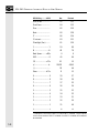
ASCII Transmission Characters
When using the SOI-260 in terminal mode, the keypad is mapped to
characters shown in the following table.
57
SOI-260 OPERATOR INTERFACE MODULE USER MANUAL
SOI-260 Key ........... ASCII
Hex
Decimal
Main Menu ...............
85
133
Prev Menu .................
84
132
Prev ...........................
82
130
Next ..........................
80
128
*F ..............................
86
134
*Contrast ...................
83
131
*Backlight (Sun) ........
81
129
Y .............................. Y
59
89
N ............................ N
4E
78
Back Space ......... <BS>
8
8
EXP ......................... E
45
69
CE ..................... <FF>
0C
12
+/- ..........................+/-
2B/2D
43/45
(.) .............................. .
2E
46
Enter ................. <CR>
D
13
9 .............................. 9
39
57
8 .............................. 8
38
56
7 .............................. 7
37
55
6 .............................. 6
36
54
5 .............................. 5
35
53
4 .............................. 4
34
52
3 .............................. 3
33
51
2 .............................. 2
32
50
1 .............................. 1
31
49
0 .......................................... 0
30
48
* These keys will not transmit a code if DIP Switch SW1-5 is enabled. They will operate
in their normal mode until SW1-5 is disabled. Once SW1-5 is disabled, the list codes will
be transmitted.
58
APPENDIX B: TERMINAL MODE
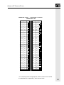
ASCII Display Characters
The following charts show the ASCII display characters and their
corresponding Hexadecimal codes.
TERMINAL MODE - SUPPORTED DISPLAY
CHARACTER SET
DEC
HEX
32
CHR
DEC
HEX
20
56
33
21
34
CHR
DEC
HEX
38
80
50
57
39
81
51
22
58
3A
82
52
35
23
59
3B
83
53
36
24
60
3C
84
54
37
25
61
3D
85
55
38
26
62
3E
86
56
39
27
63
3F
87
57
40
28
64
40
88
58
41
29
65
41
89
59
42
2A
66
42
90
5A
43
2B
67
43
91
5B
44
2C
68
44
92
5C
45
2D
69
45
93
5D
46
2E
70
46
94
5E
47
2F
71
47
95
5F
48
30
72
48
96
60
49
31
73
49
97
61
50
32
74
4A
98
62
51
33
75
4B
99
63
52
34
76
4C
100
64
53
35
77
4D
101
65
54
36
78
4E
102
66
55
37
79
4F
103
67
CHR
* All of the above characters are supported when 8 data bit communication is enabled.
Hex codes below 80H are supported by 7 data bit communication.
59
SOI-260 OPERATOR INTERFACE MODULE USER MANUAL
TERMINAL MODE - SUPPORTED DISPLAY
CHARACTER SET
DEC
HEX
104
CHR
DEC
HEX
68
160
105
69
106
CHR
DEC
HEX
A0
184
B8
161
A1
185
B9
6A
162
A2
186
BA
107
6B
163
A3
187
BB
108
6C
164
A4
188
BC
109
6D
165
A5
189
BD
110
6E
166
A6
190
BE
111
6F
167
A7
191
BF
112
70
168
A8
192
C0
113
71
169
A9
193
C1
114
72
170
AA
194
C2
115
73
171
AB
195
C3
116
74
172
AC
196
C4
117
75
173
AD
197
C5
118
76
174
AE
198
C6
119
77
175
AF
199
C7
120
78
176
B0
200
C8
121
79
177
B1
201
C9
122
7A
178
B2
202
CA
123
7B
179
B3
203
CB
204
CC
124
7C
180
B4
125
7D
181
B5
205
CD
126
7E
182
B6
206
CE
127
7F
183
B7
207
CF
CHR
* All of the above characters are supported when 8 data bit communication is enabled.
Hex codes below 80H are supported by 7 data bit communication.
60
APPENDIX B: TERMINAL MODE
TERMINAL MODE - SUPPORTED DISPLAY
CHARACTER SET
DEC
HEX
208
CHR
DEC
HEX
D0
232
E8
209
D1
233
E9
210
D2
234
EA
211
D3
235
EB
212
D4
236
EC
213
D5
237
FD
214
D6
238
EE
215
D7
239
EF
216
D8
240
F0
217
D9
241
F1
218
DA
242
F2
219
DB
243
F3
220
DC
244
F4
221
DD
245
F5
222
DE
246
F6
223
DF
247
F7
224
E0
248
F8
225
E1
249
F9
226
E2
250
FA
227
E3
251
FB
228
E4
252
FC
229
E5
253
FD
230
E6
254
FE
231
E7
255
FF
CHR
* All of the above characters are supported when 8 data bit communication is enabled.
Hex codes below 80H are supported by 7 data bit communication.
61
SOI-260 OPERATOR INTERFACE MODULE USER MANUAL
Terminal Mode--Screen Control Codes
Hex
62
Function
Description
08
BS
Back Space
0A
LF
Line Feed
0C
FF
Blanks the screen, moves the cursor to the upper left corner of
the display.
0D
CR
Moves the cursor to the extreme left position of the line.
CHAPTER TITLE
Appendix C: SOI-260 Template
63
SOI-260 OPERATOR INTERFACE USER MANUAL
3.938 inch = 100.03 mm
7.725 inch = 196.21 mm
5.625 inch = 142.87 mm
5.876 inch = 149.25 mm
.188 inch = 4.78 mm
0.125 inch = 3.18 mm
0.078 inch = 1.98 mm
3.938 in
SOI-260
Panel Cut-Out
Template
7.725 in
5.625 Inch x 7.725 Inch
142.87 mm x 196.21 mm
3.938 in
0.125 in
0.078 in
64
Note: Maximum panel thickness is 1/4" (.250)
5.625 in
5.876 in
0.188 in dia
6 places
INDEX
Index
A
Alarm test 34
ASCII 57–62
Attempt made to ”call” 50
B
Backlighting 35
Baud rate 22, 23
BL/INT 35
C
C-port menu item 21–22
Cabling 39–40, 41–45
Characters, ASCII 57–62
Check-sum: nnnn (.CFG file) 48
Checksum failed 48
Clk/cal menu item 25–26
Clock/calendar 25–26
test 34
Codes, screen control 62
COMM ERROR, Press “Y” 49
Comm ERROR PRESS Y 50
Communications
establishing 10
port 21–22, 39–40
selecting 13
test 31
upload/download enable 13–14
Computer
connections 10–11
Connections
computer 10–11
power 9
printer 11
Contrast 35
Control codes 62
Conventions 2
Cursor enable 29
D
Data bits 22, 23
Date 25–26
Day 25–26
Diagram, functional 7
DIP switches 11–14
test 31
Display
ASCII characters 59–62
control 32
test 31
Duplex, half 29
DUT reset 30
E
Errors 47–53
Establishing Comm 49
F
Factory settings 12–14
File, program test 33
Function key menus
c-port (communications port) 21–22
clk/cal (clock/calendar) 25–26
other 35–37
p-port (printer port) 23–25
reset 27
special 27–28
term (terminal mode) 28–29
test 30–34
Function keys, enabling 13
Functional diagram 7
65
SOI-260 OPERATOR INTERFACE USER MANUAL
G
O
Grounding recommendations 9–10
Other menu item 35–37
Overview, manual 2
H
P
Half duplex 29
Handshake 24
Hardware
indicator LEDs 14–15
keypad 15–20
SOI-260
description 5–7
installing 7–14
Hndshk 24
I
INF 52
Input Error 51
Installation
SOI-260 3, 7–14
Intensity 35
INVALID SECURITY 50
K
Keyboard test 31
Keypad 15–20
Keys
green 17–19
light grey 19–20
L
L/feed 24
LEDs 14–15
Line feed 24
enable 29
M
Manual
conventions 2
overview 2
Master security code 36–37
Master security enable 13
Mastr C 36–37
Memory, system test 33
Month 25–26
Mounting, environmental considerations 8
N
66
NaN (Not a number) 51
No relation 52
NOT PROGRAMMABLE 50
P-A/D 27–28
P-port menu item 23–25
Packaging instructions i
Parity 22, 24
Penabl 25
PLC not found 49
PLC not Responding 49
Point access/display 27–28
Port
communications 21–22, 39–40
communications test 31
printer 23–25, 41–45
printer test 32
selecting 13
Power, connections 9
Print screen 36
Printer
connecting 11
enable 25
port 23–25, 41–45
port test 32
Printer not Ready 51
Prn screen 36
Program file test 33
Programming 3–4
Publications, related 2–3
R
RAM fail 48
RAM test 33
READONL 52
Recommendations
grounding 9–10
wiring 9
Reset DUT 30
Reset menu item 27
S
Scale E 37
Scaling, enable 37
Screen control codes 62
Screen print 36
Security
enabling master 13
master code 36–37
Self Test Failure 51
INDEX
Simulate 35
Software 3–4
SOI-260
description 5–7
functional diagram 7
installing 3, 7–14
overview 3
SOI-SPS 3–4
Special menu item 27–28
Specifications 55–56
System memory test 33
T
Term menu item 28–29
Terminal mode, enabling 13
Terminal mode 28–29, 57–62
Test menu items 30–34
Tests
alarm 34
clock/calendar 34
comm port 31
DIP switch 31
display 31
keyboard 31
printer port 32
program file 33
RAM 33
system memory 33
TXEN 34
Time 25–26
Troubleshooting 47–53
TXEN test 34
U
Upload/download 40
Upload/download, enabling 13, 13–14
V
Version Mismatch 52
W
Warranty information ii
Watch Dog Fault 48
Watch Dog Fault Push key to reset 49
Wiring recommendations 9
Y
Year 25–26
67
SOI-260 OPERATOR INTERFACE USER MANUAL
68
Copyright © 1998 Spectrum Controls, Inc. All rights reserved.
Specifications subject to change without notice. Printed in U.S.A.
Publication 030050-07 Rev. C.0 April 1998
Corporate Headquarters
Spectrum Controls, Inc.
P.O. Box 5533 • Bellevue, Washington 98006
Fax: (425) 641-9473 • Tel: (425) 746-9481
Northeastern U.S.A. Sales Office
Spectrum Controls, Inc.
48945 Van Dyke, 4B • Utica, Michigan 48317
Fax: (586) 731-2715 • Tel: (586) 731-2397
Southeastern U.S.A. Sales Office
Spectrum Controls, Inc.
8860 Saddle Trail • Ball Ground, Georgia 30107
Fax: (678) 455-4640 • Tel: (678) 455-4615
Web Site: http://www.spectrumcontrols.com
E-mail: [email protected]