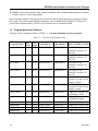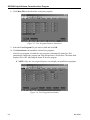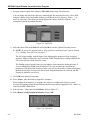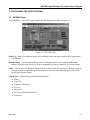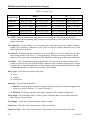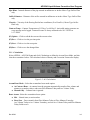
1
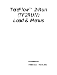
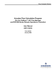
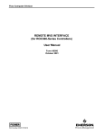
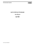
Flow Computer Division API2540 Liquid Volume Correction User Program (ROC300-Series and FloBoss™ 407 Flow Managers) (ROCLINK™ for DOS Configuration Software) User Manual (QER 03Q008) Form A6138 May 2004 API2540 Liquid Volume Correction User Program Revision Tracking Sheet May 2004 This manual may be revised from time to time to incorporate new or updated information. The revision level of each page is indicated at the bottom of the page opposite of the page number. A change in revision level to any page also changes the date of the manual that appears on the front cover. Listed below is the revision level of each page. Page Revision Pages i, 1-1 05/04 All pages 05/03 All pages 01/03 FloBoss and ROCLINK are marks of one of the Emerson Process Management companies. The Emerson logo is a trademark and service mark of Emerson Electric Co. All other marks are the property of their respective owners. © Fisher Controls International, LLC. 2003-2004. All rights reserved. Printed in the U.S.A. While this information is presented in good faith and believed to be accurate, Fisher Controls does not guarantee satisfactory results from reliance upon such information. Nothing contained herein is to be construed as a warranty or guarantee, express or implied, regarding the performance, merchantability, fitness or any other matter with respect to the products, nor as a recommendation to use any product or process in conflict with any patent. Fisher Controls reserves the right, without notice, to alter or improve the designs or specifications of the products described herein. ii Rev Rev05/03 05/04 API2540 Liquid Volume Correction User Program Table of Contents Page 1 Getting Started..................................................................................................................................... 1-1 1.1 Scope of this Manual ......................................................................................................... 1-1 1.2 Organization of this Manual.............................................................................................. 1-1 1.3 API2540 Liquid Volume Correction User Program Overview......................................... 1-1 1.4 Domain Limitations Handling........................................................................................... 1-2 1.5 Program Names and Versions ........................................................................................... 1-3 2 Installing the User Program................................................................................................................. 2-1 2.1 Customizing ROCLINK.................................................................................................... 2-1 2.2 Downloading the User Program ........................................................................................ 2-2 2.3 Update Firmware ............................................................................................................... 2-5 2.3.1 Altering Your .LST File ..................................................................................... 2-7 3 Configuring the User Program ............................................................................................................ 3-1 3.1 API2540 Setup................................................................................................................... 3-1 3.1.1 Calculations ........................................................................................................ 3-3 3.1.2 Volume-Time Snapshot...................................................................................... 3-4 3.1.3 Alarms ................................................................................................................ 3-5 3.1.4 Inputs .................................................................................................................. 3-6 3.1.5 Slippage Factors ................................................................................................. 3-7 3.2 Data Transfer ..................................................................................................................... 3-8 Appendix A Standards........................................................................................................................... A-1 Appendix B Domain Violations .............................................................................................................B-1 Appendix C Engineering Units ..............................................................................................................C-1 Index ........................................................................................................................................................ I-1 Rev 05/03 iii API2540 Liquid Volume Correction User Program iv Rev 05/03 API2540 Liquid Volume Correction User Program 1 GETTING STARTED 1.1 Scope of this Manual This document serves as a user manual for the API2540 Liquid Volume Correction User Program (QER 03Q008), intended for use with the ROC300-series of Remote Operation Controllers (ROCs) with a FlashPAC, version 2.12 or greater, and FloBoss™ 407 Flow Manager, version 1.08 or greater. This manual describes how to download, configure, and monitor the program. The user program is accessed using ROCLINK™ for DOS configuration software version 2.23. The configuration software uses an IBM-compatible computer and Windows® Operating System. For information on use of the API2540 program with ROCLINK 800 configuration software, refer to user manual Form A6167. 1.2 Organization of this Manual In this manual, the sections are arranged to provide information in the order in which it is required for first-time users. Once you become familiar with the procedures, and the software is running in a ROC or FloBoss 407, use the manual as a reference tool. The manual is organized into the following major sections: Section 1 Getting Started Section 2 Installing the User Program Section 3 Configuring the User Program Appendix A Standards Appendix B Domain Violations Appendix C Engineering Units This manual assumes that the user is familiar with the ROC300-series and FloBoss 407 units and their configuration. For additional information, refer to the: ♦ Type ROC306/ROC312 Remote Operations Controller Instruction Manual (Form A4630). ♦ Type ROC364 Remote Operations Controller Instruction Manual (Form A4193). ♦ FloBoss 407 Flow Manager Instruction Manual (Form A6013). ♦ RL101 ROCLINK Configuration Software User Manual (Form A6051). NOTE: “ROC” is used in this manual to stand for all ROC and FloBoss devices. 1.3 API2540 Liquid Volume Correction User Program Overview The Liquid Correction Program is designed for the ROC300-series units equipped with FlashPACs and the FloBoss 407. The Liquid Correction Program corrects the measured flow of crude oils, oil generalized products, LPG, and water by converting values to standard temperature and pressure levels. The Liquid Correction Program monitors the current flow rate, temperature, and pressure, and to calculate a corrected flow value for standard conditions based upon density value, sediment, and water percent value, vapor pressure, and the meter slippage factor. 1-1 Rev 05/04 Rev 05/03 API2540 Liquid Volume Correction User Program The Liquid Correction Program accumulates the volume of the flowing fluid and can be configured to perform calculations for up to three different flows in the ROC306 and ROC312, five flows in the ROC364, or four flows in the FloBoss 407. The Liquid Correction Program tracks two accumulated volumes for each flow. One accumulation is the volume since contract hour or last manual reset and the second accumulation is a running total that rolls over at 9,999,999. At contract hour or manual reset, flow and minutes today are transferred to flow and minutes yesterday. The Liquid Correction Program supports the following liquids: ♦ Crude oil. ♦ Generalized oil products (jet fuel, diesel, oil, and gasoline). ♦ LPG (Liquefied Petroleum Gas). ♦ Water. The Liquid Correction Program supports the following standards: ♦ API2540 Tables 5A, 5B, 6A, 6B, 34, 53, 53A, 53B, 54, API21, API5, AGA3/1992 and was developed according to API/ANSI/AGA standards. Refer to Appendix A for a list of all applicable standards. The Liquid Correction Program supports the following types of inputs: ♦ Pulse (mass or volume). ♦ Analog Flow (mass or volume). ♦ Analog Differential Pressure (DP). ♦ Density. ♦ Vapor Pressure. ♦ Water and Sediments. An uncorrected flow can be determined by one of the following inputs: ♦ Pulse Input (such as from a turbine). ♦ Analog Input (such as from a Vortex or MicroMotion). ♦ Differential Orifice Metering (flange taps only). 1.4 Domain Limitations Handling The Liquid Correction Program application domain is limited, by API standards, to correcting the flow of densities, pressures, and temperatures within a custody transfer degree of accuracy. The domain borders vary according to the product class and parameter values. The calculation automatically adjusts the Liquid Type between LPG and Crude Oil if the input density fluxuates Whenever a domain violation occurs, an error message displays and stored in the Event Log, with the ERR tag, the Domain Limit as “old value”, and the Current Value of the parameter. When the violation clears, “No Error” displays and a clear event is logged with the CLR tag. A real-time stamp is appended to each event. In error mode, calculations use the closest domain formulas. Rev 05/03 1-2 API2540 Liquid Volume Correction User Program NOTE: Further interpretation of the volumes calculated and accumulated during domain violation periods is the user’s sole responsibility. Because domain limits for flowing pressure corrections and flowing temperature corrections overlap, the Liquid Correction Program assumes temperature-driven domain below 500 kPa (75 PSIA) and pressure-driven domain above 500 kPa. The associated error is less than 50 PPM. 1.5 Program Names and Versions Program versions and names display in Table 1-1. You must download two user programs. Table 1-1. Versions and Program Names User Code Blocks Point 28-29 C0000-CFFFF Data Blocks ROC or FloBoss Version api_3a.h00 User Task 3 A0000-ABFFF apitbl3a.h00 3 28-29 C0000-CFFFF A0000-ABFFF api_3b.h00 3 28-29 D0000-DFFFF B4000-BFFFF apitbl3b.h00 3 28-29 D0000-DFFFF B4000-BFFFF api3a_ic.h00 3 28-29 A0000-AFFFF B0000-BBFFF ap3tblic.h00 3 28-29 A0000-AFFFF B0000-BBFFF api4a_ic.h00 3 28-29 60000-6FFFF 70000-7BFFF ap4tblic.h00 3 28-29 60000-6FFFF 70000-7BFFF api_4a.h00 apitbl4a.h00 api_4b.h00 apitbl4b.h00 3 3 3 3 28-29 28-29 28-29 28-29 74000-7FFF 74000-7FFF 60000-6BFFF 60000-6BFFF ROC306/312/364 FlashPAC versions 2.12 and 2.20 ROC306/312/364 FlashPAC versions 2.12 and 2.20 ROC306/312/364 FlashPAC versions 2.12 and 2.20 ROC306/312/364 FlashPAC versions 2.12 and 2.20 ROC306/312 FlashPAC versions 2.12 and 2.20 for Industry Canada ROC306/312 FlashPAC versions 2.12 and 2.20 for Industry Canada FloBoss 407 version 1.08 for Industry Canada FloBoss 407 version 1.08 for Industry Canada FloBoss 407, version 1.08 FloBoss 407, version 1.08 FloBoss 407, version 1.08 FloBoss 407, version 1.08 Program Name 1-3 C0000-CFFFF C0000-CFFFF B0000-BFFFF B0000-BFFFF Rev 05/03 API2540 Liquid Volume Correction User Program Rev 05/03 1-4 API2540 Liquid Volume Correction User Program 2 INSTALLING THE USER PROGRAM This section describes how to download and install the user program into the ROC306/312/364 with a FlashPAC (version 2.12 or greater) and FloBoss 407 Flow Manager (version 1.08 or greater), using ROCLINK for DOS Configuration Software (version 2.23). For additional information on downloading the program, checking memory allocation, and enabling the program, refer to the RL101 ROCLINK Configuration Software User Manual (Form A6051). 2.1 Customizing ROCLINK ROCLINK for DOS requires several files to use the API2540 Liquid Volume Correction User Program: 1. Navigate to the CD-ROM directory where the gas flow calculation installation files are located. Program files are typically located in the Program Files/ROCLINK Files folder on the CD-ROM. 2. Select and Copy the following files: ♦ menu3.txt ♦ menu4.txt ♦ scl_api1.tpl ♦ scl_reg1.tpl ♦ tlplist.txt 3. Paste the files in to the ROCLINK default working directory. The default directory is located at: C:\ROCLINK NOTE: Select Yes if prompted to overwrite existing files. 4. Right-mouse click on the selected files. 5. Select Properties. Figure 2-1. Properties Rev 05/03 2-1 API2540 Liquid Volume Correction User Program 6. De-select the Read-only Attribute for each program file that has the Read-only Attribute set. If the files remain Read-only, ROCLINK will not connect to the ROC or FloBoss. Figure 2-2. Attributes 7. Click OK. NOTE: Customize ROCLINK before downloading the user program. 2.2 Downloading the User Program To download the user program: 1. Connect the ROC or FloBoss to your computer through the LOI port. 2. Launch and logon to ROCLINK for DOS. 3. Select Utilities > User Programs. Figure 2-3. User Programs 2-2 Rev 05/03 API2540 Liquid Volume Correction User Program 4. Determine the Unused Memory Blocks. The memory location must be available for the specific user program that you are loading. 5. Determine whether program A or B is required. The A and B programs are identical other than the location in which they load into ROC memory. Refer to Table 1-1. 6. Click DownLoad and select the user program file to download from the CD-ROM. Program files are typically located in the Program Files/ROCLINK Files folder. The Open File dialog displays the names of all the files that have the .H00 extension. NOTE: You must download two user programs. Refer to Table 1-1, Versions and Program Names. Figure 2-4. Open File 7. Select the User Program file you desire to load and click OK. Device ROC306/312/364 ROC306/312/364 ROC306/312 (Industry Canada) FloBoss 407 FloBoss 407 FloBoss 407 (Industry Canada) Rev 05/03 User Program Names api_3a.h00 and apitbl3a.h00 api_3b.h00 and apitbl3b.h00 api3a_ic.h00 and ap3tblic.h00 api_4a.h00 and apitbl4a.h00 api_4b.h00 and apitbl4b.h00 api4a_ic.h00 and ap4tblic.h00 2-3 API2540 Liquid Volume Correction User Program 8. Click More Files to download the second user program. Figure 2-5. User Programs Ready to Download 9. Select the User Program file you desire to load and click OK. 10. Click DownLoad to download the selected user programs. After the user program is loaded, the user program is automatically turned on. This automatically enables the program run Flags and performs a Warm Start. The Status field displays ON or OFF indicating the Status of the user program. NOTE: Only one user program displays even though you installed two programs. Figure 2-6. User Program Downloaded 2-4 Rev 05/03 API2540 Liquid Volume Correction User Program 11. Select System > Flags. Refer to Figure 2-7. Figure 2-7. ROC Flags 10. Select Active under the Calc User Program option. Refer to Figure 2-7. 11. Ensure that the Write to EEPROM button displays Yes. Refer to Figure 2-7. 12. Click Save. This ensures that the program automatically restarts after a Cold Start. NOTE: Remember to de-select the Read-only Property of all user program files. Refer to Figure 2-2. 2.3 Update Firmware If the firmware version does not match the recommended version displayed in Table 1-1: Versions and Program Names, proceed with the following firmware update procedure. The firmware is available from your sales representative or from technical support. Update Firmware updates the internal firmware Flash memory of the FloBoss 407 or the ROC300series FlashPAC by loading it from a file. NOTE: The Update Firmware procedure clears the configuration of the ROC or FloBoss and reloads configuration from EEPROM after the update procedure is completed. The Event Log, Alarm Log, Audit Log, and History logs are cleared. To preserve the contents of the logs, be sure to save them to a file (Collect ROC Data) before starting. The Event, Alarm, and History Logs cannot be reloaded. 1. Create a backup of the log data using File > Collect ROC Data > All. 2. Save all FSTs to a disk file. 3. Select System > Flags. Refer to Figure 2-7. 4. Click Write to EEPROM and click Save and wait for the save process to complete. This may take several minutes for ROC300-series units. 5. Read the README text file included with the firmware update. 6. Select File > Update Firmware. Rev 05/03 2-5 API2540 Liquid Volume Correction User Program 7. Navigate to the location of the firmware File Name in the Open File dialog box. You can change the path to the directory containing the file using the Directory / Drive field using the <Enter> key or by double-clicking on a different drive or directory. Select “..” to move up a directory. The Open File dialog displays the names of all files with the .LST extension located in the current directory. Figure 2-8. Open File 8. Select the desired file in the Files list and click OK to start the Update Firmware process. NOTE: If you receive an error such as “File gas85.fsr is missing or bad,” refer to Section 2.3.1, Altering Your .LST File, on page 2-7. The file begins loading, with the Status Line displaying the progress in four categories: Segment, Address, Block Size, and Total Sent. While Flash memory is being modified, the I/O is not read, but is held at the last values. The loading process typically takes several minutes; do not disturb it during this time. If you are running ROCLINK under Windows 95/98, you can adjust the miscellaneous properties of the ROCLINK window to allow you to leave the window without interrupting the download (Allow Screen Saver and Always Suspend should not be selected, and Idle Sensitivity should be set to Low). 9. Click OK in the history lost prompt. 10. Press <Enter> after the firmware upgrade is complete. When loading of the firmware is complete, the action is recorded in the Event Log and a message line appears saying that the FloBoss has been successfully upgraded. Press <Enter> to return to the ROCLINK menus. 11. Select System > Flags and click Cold Start. Refer to Figure 2-7. 12. Select Restore config from flash/defaults and click OK. Figure 2-9. Cold Start 2-6 Rev 05/03 API2540 Liquid Volume Correction User Program 13. Click Save to reload the configuration from EEPROM. Refer to Figure 2-7. 14. Check the configuration and the FSTs. If the configurations are incorrect, reload the configuration and the FSTs from the files previously created. 2.3.1 Altering Your .LST File You may be required to change the path in your .lst file if you copied the firmware files to a different directory than the directory that was specified in the Readme.txt. To alter the path, follow these steps: 1. Open the .lst file in a text editor such as Notepad. Figure 2-10. Changing a Directory Path 2. Change the path to reflect the same directory where you copied the upgrade files. Be careful not to alter the file names. 3. Save your changes and exit Notepad. Rev 05/03 2-7 API2540 Liquid Volume Correction User Program 2-8 Rev 05/03 API2540 Liquid Volume Correction User Program 3 CONFIGURING THE USER PROGRAM 3.1 API2540 Setup Select API2540 > API 2540 Setup to display the API Setup screen. Refer to Figure 3-1. Figure 3-1. API 2540 Setup Point Tag – Enter a ten-character name used to label the meter run upon which the flow computation is performed. Domain Status – Current Domain Status, such as violations, inactive, or everything within limits. Statuses are archived in Event Log. Refer to Appendix B, Domain Violations, for error messages. Units – Click to select US (English / Imperial) units or Metric units for calculations. If Metric units are selected, then the calculation expects all inputs to be in terms of the indicated units (such as KPa for the Static Pressure input). Liquid Type – Select the type of liquid in the meter run: ♦ Water. ♦ Crude Oil. ♦ Gasoline, Condensate. ♦ Jet Fuel. ♦ Diesel Oil. ♦ LPG (Liquefied Petroleum Gas). ♦ Transition. Rev 05/03 3-1 API2540 Liquid Volume Correction User Program Table 3-1. Liquid Types Liquid Type Crude Oil Gasoline * Jet Fuel* Diesel* LPG Transition* Metric Low Density below 610.5 kg/m3 below 653 kg/m3 below 787.5 kg/m3 below 829 kg/m3 below 495 kg/m3 below 771 kg/m3 High Density above 1075 kg/m3 above 770.5 kg/m3 above 829 kg/m3 above 1075 kg/m3 above 610.5 kg/m3 above 787 kg/m3 US Low Density above 100 deg API above 85 deg API above 48 deg API above 40 deg API above 155 deg API above 52 deg API High Density below 0 deg API below 52 deg API below 37 deg API below 0 deg API below 100 deg API below 48 deg API Low NOTE: *Domain violations are triggered at contract conditions. The program automatically switches to the proper operating range, using the corrected density value, when one of the indicated ranges is selected. Calc Vapor Prs – Click to unlock (Yes) or lock (No) the calculated vapor pressure feature. When the Liquid Type is Gasoline, Condensate, or LPG, the Calc Vapor Prs option is unlocked (Yes), for all other liquids it is locked (No). Scan Period – 50-millisecond interval the flow is set to run. When it is set to less than 10ms, the flow does not run, and the “Not Active !!!” message displays. You must reset this parameter with the number of flows, particular configuration of the liquid flow, and general configuration of the ROC. Scan Time – Value calculated and displayed by the ROC for each scan, in seconds. If an unrealistic setting is in place for the Scan Period, the ROC cannot keep the calculation speed in place with the desired value, so significant differences will occur between the Scan Period and Scan Time, with a correspondent increase in Central Processor Unit (CPU) loading. Meter Type – Select the type of meter being used: ♦ Pulse. ♦ Analog. ♦ Orifice Plate. Alarming – Select Enable or Disabled. ♦ Enabled – Click the Alarms button to configure alarms for this point. Alarms are logged to the Alarm Log. Refer to Section 3.1.3, Alarms, on page 3-5. ♦ Disabled – No alarm generates for this point, regardless of the Alarms configuration. Meter Input – Select the Meter Input: Volume or Mass. When the Meter Type is Orifice Plate, the Meter Input is always Volume. Calc Output – Select the Calculation Output: Volume or Mass. Static Press – Select the Static Pressure mode: Gauge or Absolute. Static Press Tap – Select if the Static Pressure is Downstream or Upstream of the orifice plate. 3-2 Rev 05/03 API2540 Liquid Volume Correction User Program Pipe Diam – Internal diameter of the pipe entered in millimeters or inches. Meter Type Orifice Plate only. Orifice Diameter – Diameter of the orifice entered in millimeters or inches. Meter Type Orifice Plate only. Viscosity – Viscosity of the flowing fluid at base conditions (cP or Lbm/Ft-s). Meter Type Orifice Plate only. Contract Temp – Contract Temperature of 15 Deg C or 60 Deg F. An invalid setting generates an error message and is logged. Contract Pressure is always assumed to be 101.325 kPa or 14.73 PSIA. (F1)Update – Click to refresh the screen with current values. (F2)Prev – Click to view the previous point. (F3)Next – Click to view the next point. (F8)Save – Click to save the changed data. 3.1.1 Calculations Select API2540 > API 2540 Setup and click Calculations to define the Accum Reset Mode, and also clear the accumulated values. The calculated values of Density and Correction Factors also display. Figure 3-2. API Calculations Accum Reset Mode – Select the accumulated reset mode option: ♦ At Contract Hour – At contract hour the program automatically transfers flow volume and minutes to yesterday values, and resets Flow Minutes Today and Acc Volume Today. ♦ Manual Only – Contract hour is ignored. Reset Accum– Select the accumulated reset option: ♦ Idle – Normal state, no action taken. ♦ Reset Now – Forces transfer from Flow Minutes Today to Flow Minutes Yesterday, Acc Volume Today to Acc Volume Yesterday, and sets Acc Volume Today and Flow Minutes Today fields to zero. Rev 05/03 3-3 API2540 Liquid Volume Correction User Program Densities Input Value – Displays actual input read (or set) density in kg/m3, lbm/cft, or Deg API. Flow Conditions – Displays actual flow density used in calculations in kg/m3, lbm/cft, or Deg API. At Contract – Displays actual base density used in calculations in kg/m3, lbm/cft, or Deg API. Correction Factors With Temperature – Temperature Correction factor currently used in flow calculation. With Pressure – Pressure Correction Factor currently used in flow calculation. Meter Slippage – Actual Meter Slippage factor used in calculations. The value is read-only and values are calculated and transferred from the Meter Slippage screen. Refer to Section 3.1.5, Slippage Factors, on page 3-7. 3.1.2 Volume-Time Snapshot Select API2540 > API 2540 Setup and click Volume-Time Snapshot to view Rates-Volumes and Flow Minutes. Figure 3-3. Volume-Time Snapshot Rates-Volumes Inst Flow Raw – Displays daily flow uncorrected in m3/day or bbl/day. Inst Flow Corrected – Displays daily flow corrected to contract conditions in m3/day or bbl/day. Acc Volume Today – Accumulated corrected volume since contract hour or last manual reset, flow units. At contract hour or manual reset, values transfer to Flow Minutes Yesterday. Acc Volume Yesday – Accumulated corrected volume yesterday, flow units. Acc Volume Forever – Accumulated corrected volume since last rollover, flow units. Rollovers at 9,999,999 (ten million less 1). 3-4 Rev 05/03 API2540 Liquid Volume Correction User Program Flow Minutes Today – Flow Minutes Today. Yesterday – Flow Minutes Yesterday. Hrs. Forever – Flow Hours Forever. 3.1.3 Alarms Select API2540 > API 2540 Setup and select Alarms Enabled. Click Alarms to define low, high, low flow alarms and Spontaneous Report-by-Exception (RBX) Alarming. Refer to Figure 3-4. Figure 3-4. Alarms Low Flow Cutoff – When the Meter Input value of the metering device is less than the Low Flow Cutoff value, the calculated flow is equal to zero, (m3/Day or BBL/Day). Low Alarm – Limit value, in engineering units, to which the calculated flow must fall to generate a Low Alarm, (m3/Day or BBL/Day). High Alarm – Limit value, in engineering units, to which the calculated flow must rise to generate a High Alarm, (m3/Day or BBL/Day). RBX Alarming – Currently, there are no communication programs available to handle API 2540 notifications. However, the alarms and Spontaneous Report-by-Exception (RBX) tags are logged into the Alarm Log. Disabled – Select Disabled to turn RBX Alarming Off. On Alarm Set – When the point enters an alarm condition, the ROC generates a Report-ByException message. On Alarm Clear – When the point leaves an alarm condition, the ROC generates a Report-ByException message. On Alarm Set & Clear – In either condition, an RBX message generates. Note that RBX Alarming also requires the communications port to be properly configured. Active Alarms – Displays any alarms that are currently active. Rev 05/03 3-5 API2540 Liquid Volume Correction User Program 3.1.4 Inputs Select API2540 > API 2540 Setup and click Inputs to define the Meter Input, Temperature Input, Static Prs. Input, Vapor Prs. Input, Density Input, and Sediment & Water inputs. Figure 3-5. Inputs Meter Input – Source of the uncorrected measured flow. Typically, this links to a Pulse Input engineering units Value, or the Analog Input Filter engineering unit value. Softpoint parameters, FST Registers, or manual (Undefined) mode are also accepted. The value transferred or set displays as the (Meter) Value field. When using a Pulse Input, this is typically configured as “rate,” but the user program calculates pulse values starting from the Accumulated Pulses (Accum’d Pulses) in the Pulse Input (m3 or kg for metric and bbl or lbm for US). If the Meter Type is configured as Pulse Input, and the actual value is manual (Undefined), or from a different register in the ROC (such as a Softpoint), the user program interprets the number as a daily rate (kg, m3, lbm or bbl per day). When using an Analog Input, such as from a Vortex transmitter, the rate must be m3/hour or kg/hour in metric, and bbl/hour or lbm/h in US units. When using a differential Analog Input for orifice metering, the scaling must be kPa in Metric and in. H2O in US units. Temperature Input – Location where the process temperature of the fluid is originated. Typically, this floating-point parameter is assigned to the “Filter” engineering units (EU) value of an Analog Input. Softpoint parameters, FST registers, or manual (Undefined) mode are also accepted. The value transferred or set displays as the (Temperature) Value in Deg C or Deg F. Static Prs. Input – Location where pressure of the fluid is originated. The pressure is assumed to be consistent with the Vapor Pressure. Typically, this floating-point parameter is assigned to the “Filter” EU value of an Analog Input or MVS. Softpoint parameters, FST registers, or manual (Undefined) mode are also valid. The value transferred or set displays as the (Pressure) Value in kPa or PSI. Vapor Prs. Input – Location where the vapor pressure of the fluid is originated. The vapor pressure is assumed to be absolute pressure and consistent with the Process Pressure (see above). Typically, this floating-point parameter is assigned to the “Filter” EU value of an Analog Input, Softpoint, FST Register, or manual (Undefined) mode. The value transferred or set displays as the Value in kPa or PSI. 3-6 Rev 05/03 API2540 Liquid Volume Correction User Program Density Input – Location where the density of the fluid is originated. There are two typical practical applications: 1. This parameter is manually (Undefined) entered, to a value certified by a laboratory. The Value is assumed to be at base temperature and pressure, except API rounding. No corrections are made on this Value. 2. A flow density meter can be assigned to the “Filter” EU value of an Analog Input. The current Value of the floating-point parameter is assumed at flow conditions, so temperature and pressure corrections are applied. Softpoint and FST registers are also accepted. The value transferred or set displays as the (Density) Value in kg / m3 or Deg API. Sediment & Water Input – Analog Input weight percentage, such as from a BS&W device, Softpoint, FST Register, or manual (Undefined) entry. Valid Domain 0-100.a 3.1.5 Slippage Factors Select API2540 > API 2540 Setup and click Slippage Factors to “fine tune” each individual meter, based on proven calibration data described in API Manual of Petroleum Standards, Chapter 12. This screen is only accessible for Pulse or Analog Meter Types. Figure 3-6. Meter Slippage Factors Up to five different Meter Slippage Factors may be entered for various flow rates. 1. If the first flow rate is set to 0.0, the rest of the table is ignored and a Meter Slippage Factor of 1.0 is used. 2. If only one flow rate / meter factor pair is entered, the program uses that Meter Slippage Factor for all flow rates. Enter a unique Meter Slippage Factor. 3. If more than one flow rate / meter factor pair is entered, the program uses linear interpolation to arrive at the Meter Slippage Factor for the current raw flow rate. Each meter flow rate entered must be higher than the previous flow rate entered, such as: Meter Value 1 < Meter Value 2 < Meter Value 3, and so forth. 4. If an error occurs due to improper configuration, such as negative numbers, the program sets the Meter Slippage Factor to 1.0. Meter Value 1 – First flow rate for 1st Meter Slippage Factor. Typically 20% of maximum flow. Factor 1 – Meter Slippage Factor for 1st flow rate. Rev 05/03 3-7 API2540 Liquid Volume Correction User Program Meter Value 2 – Second flow rate for 2nd Meter Slippage Factor. Typically 40% of maximum flow. Factor 2 – Meter Slippage Factor for 2nd flow rate. Meter Value 3 – Third flow rate for 3rd Meter Slippage Factor. Typically 60% of maximum flow. Factor 3 – Meter Slippage Factor for 3rd flow rate. Meter Value 4 – Fourth flow rate for 4th Meter Slippage Factor. Typically 80% of maximum flow. Factor 4 – Meter Slippage Factor for 4th flow rate. Meter Value 5 – Fifth flow rate for 5th Meter Slippage Factor. Typically 100% of maximum flow. Factor 5 – Meter Slippage Factor for 5th flow rate. Calculated Factor – Displays the actual calculated meter factor to be used in calculations. The value is transferred to the API Calculations (Figure 3-2) as Meter Slippage Factor. 3.2 Data Transfer Select API2540 > Data Transfer to configure eight individual register data transfers. The values defined in Source definition data 1 to 8 are transferred into target Destination data 1 to 8. The actual value for each field displays in the corresponding Value field. Only floating-point values can be transferred, even though other data options are selectable. The Register Transfer screen is set to run by setting the Scan Period to a value greater than zero. The actual Scan Time is typically 2 seconds. Figure 3-7. Data Transfer 3-8 Rev 05/03 API2540 Liquid Volume Correction User Program APPENDIX A STANDARDS The following API and ASTM standards were used to develop the API2540 Liquid Volume Correction User Program: ASTM D 1250-80 Tables 34, 53, 53A, 53B, 54, 54A, and 54B 1980. Manual of Petroleum Measurement Standards Chapter 11.1 of Volume Correction Factors Volume X - Background, Development, and Program Documentation. API Standard 2540, first edition. 1984. Manual of Petroleum Measurement Standards Chapter 11.2.1 of Compressibility Factors for Hydrocarbons: 638 - 1074 Kilograms per Cubic Meter Range. American Petroleum Institute, first edition. 1986. Manual of Petroleum Measurement Standards Chapter 11.2.2M of Compressibility Factors for Hydrocarbons: 350 - 637 Kilograms per Cubic Meter Density (15°C) and -46°C to 60°C Metering Temperature. American Petroleum Institute, first edition. 1981 reaffirmed 1987. Manual of Petroleum Measurement Standards Chapter 12 of Calculation of Petroleum Quantities Field Manual. Section 2 of Instructions for Calculating Liquid petroleum Quantities measured by Turbine or Displacement Meters. American Petroleum Institute, first edition. 1993. Manual of Petroleum Measurement Standards Chapter 21 of Flow Measurement Using Electronic Metering Systems. American Petroleum Institute, first edition. 1990. American Gas Association. Report No.3 of Orifice Metering American Petroleum Institute, third edition. API Manual of Petroleum Measurement Standards. Chapter 11 of Physical Properties Data Addendum to Section 2, Part 2 Correlation for Vapor Pressure for Commercial Natural Gas Liquids. Rev 05/03 A-1 API2540 Liquid Volume Correction User Program A-2 Rev 05/03 API2540 Liquid Volume Correction User Program APPENDIX B DOMAIN VIOLATIONS Error Message Low Temp. (Water) Low Temp. (Oil Prod) Low Temp. (LPG) High Temp (Water) Critical Temp. LPG High Temp. (Oil Prod) High Press. (Oil Prod) Low Density Oil Low Dens. Gasoline Low Dens. Jet Low Density Diesel Low Density (P.drv) Low Density LPG Low Trans Zone Low Density Oil Low Dens. Gasoline Low Density Jet Fuel Low Density Diesel Low Density (P.drv) Rev 05/03 Units Metric US Metric US Metric US Metric US Metric US Metric Description Temperature below 0 Deg C Temperature below 32 Deg F Temperature below -18 Deg C Temperature below 0 Deg F Temperature below -45 Deg C Temperature below -20 Deg F Temperature above saturation curve at actual pressure Temperature above saturation curve at actual pressure Temperature above 55 Deg C Temperature above 120 Deg F Pressure less than 500 kPa Metric Crude oil or gasoline, density 653-778.5, temperature over 90 Deg C Metric Crude oil or jet fuel, density 779.5-824, temperature over 125 Deg C Metric Crude oil or Diesel oil, density 824.5-1075, temperature over 150 Deg C Metric Pressure over 500 kPa, temperature over 90 Deg C US Pressure less than 75 PSIA US Crude oil or gasoline, density 50.1-100, temperature over 200 Deg F US Crude oil or jet fuel, density 40.1-50, temperature over 250 Deg F US Crude oil or Diesel oil, density 0-40, temperature over 200 Deg F US Pressure exceeding 75 PSIA, temperature greater than 200 Deg F Metric Pressure exceeding 10300 kPa US Pressure exceeding 1450 PSIA Metric Crude oil, density below 610.5 kg/m3 Metric Gasoline, density below 653 kg/m3 Metric Fuel Jet Fuel, density below 787.5 kg/m3 Metric Diesel oil, density below 829 kg/m3 Metric Oil products, press domain, density below 638 kg/m3 Metric LPG, density below 495 kg/m3 Metric Density in transition area below 770.5 kg/m3 US Crude oil, density above 100 Deg API US Gasoline, density above 85 Deg API US Jet Fuel, density above 48 Deg API US Diesel oil, density above 37 Deg API US Oil products, press domain, density above 90 Deg API B-1 API2540 Liquid Volume Correction User Program Error Message Low Density LPG Low Trans. Zone High Density Oil High Dens. Gasoline High Dens. Jet Fuel High Density Diesel High Density (P.dry) High Density LPG High Trans Zone High Density Oil High Dens. Gasoline High Dens. Jet Fuel High Density Diesel High Density (P.drv) High Density LPG High Trans. Zone Low Sed & Water High Sed & Water Low Meter Factor High Meter Factor High Vapor Pressure Invalid Base Temp Tables Not Found! Inside Domain (OK) Not Active!! B-2 Units US US Metric Metric Metric Metric Metric Metric US US US US US US US Metric Description LPG, density above 155 Deg API Density in transition area above 52 Deg API Crude oil, density above 1075 kg/m3 Gasoline, density above 770.5 kg/m3 Jet Fuel, density above 829 kg/m3 Diesel oil, density above 1075 kg/m3 Oil products, press domain, density above1075 kg/m3 LPG, density above 610.5 kg/m3 Density in transition area below 48 Deg API Crude Oil, density below 0 Deg API Gasoline, density below 52 Deg API Jet fuel, density below 37 Deg API Diesel oil, density below 0 Deg API Oil products, press domain, density below 0 Deg API LPG, density below 100 Deg API Density in transition area above 787.5 kg/m3 Sediment & water is negative Sediment & water is greater than 100% Meter Factor below 0.2 Meter Factor above 3 Vapor Pressure greater than Static Pressure Metric Base Temperature differs from 15 Deg C US Base Temperature different from 60 Deg F API Tables 34, 53 and 54 not loaded or corrupted All parameters within domain Flow not running Rev 05/03 API2540 Liquid Volume Correction User Program APPENDIX C ENGINEERING UNITS Inputs Outputs Metric Units Pulse Meter kg if mass, m3 if volume Analog Meter kg/hour if mass, m3 if volume Differential Meter kPa Static Pressure kPa Temperature Deg C Density kg/m3 Viscosity cP Flow E3 kg/day if mass, m3/day if volume Density kg/m3 US Units Inputs Outputs Rev 05/03 Pulse Meter Analog Differential Meter Static Pressure Temperature Density Viscosity Flow Density lbm if mass, US bbl if volume Meter lbm/hour if mass, bbl/hour if volume inches Water PSI Deg F Deg API if Oil Products, lbm/cuft if water lbm / ft*sec E3 lbm/day if mass, US bbl/day if volume Deg API if Oil Products, lbm/cuft if water C-1 API2540 Liquid Volume Correction User Program C-2 Rev 05/03 API2540 Liquid Volume Correction User Program INDEX .H00 .......................................................1-3, 2-3 .LST .......................................................2-6, 2-7 Acc Volume Forever .................................... 3-4 Acc Volume Today....................................... 3-4 Acc Volume Yesday..................................... 3-4 Accum Reset Mode ...................................... 3-3 Active Alarms............................................... 3-5 Alarming....................................................... 3-2 Alarms .......................................................... 3-5 Altering Your .LST File ............................... 2-7 API Calculations........................................... 3-3 API2540 Setup.............................................. 3-1 At Contract ................................................... 3-4 Calc Output................................................... 3-2 Calc Vapor Prs.............................................. 3-2 Calculated Factor.......................................... 3-8 Calculations .................................................. 3-3 Cold Start...................................................... 2-6 Contract Temp .............................................. 3-3 Correction Factors ........................................ 3-4 Customizing.................................................. 2-1 Customizing ROCLINK............................... 2-1 Data Transfer ................................................ 3-8 Densities ....................................................... 3-4 Density Input ................................................ 3-7 Disabled ........................................................ 3-5 Domain Limitations Handling...................... 1-2 Domain Status .............................................. 3-1 Domain Violations........................................B-1 DownLoad .................................................... 2-3 Downloading the User Program ................... 2-2 Engineering Units .........................................C-1 English .......................................................... 3-1 Error Message...............................................B-1 Extensions .H00 .................................................1-3, 2-3 .LST .................................................2-6, 2-7 Factor 1 - 5.................................................... 3-7 Figure 2-1. Properties ................................... 2-1 Figure 2-2. Attributes ................................... 2-2 Figure 2-3. User Programs ........................... 2-2 Figure 2-4. Open File.................................... 2-3 Figure 2-5. User Programs Ready to Download ................................................................... 2-4 Rev 05/03 Figure 2-6. User Program Downloaded........ 2-4 Figure 2-7. ROC Flags.................................. 2-5 Figure 2-8. Open File.................................... 2-6 Figure 2-9. Cold Start ................................... 2-6 Figure 2-10. Changing a Directory Path....... 2-7 Figure 3-1. API 2540 Setup .......................... 3-1 Figure 3-2. API Calculations ........................ 3-3 Figure 3-3. Volume-Time Snapshot ............. 3-4 Figure 3-4. Alarms........................................ 3-5 Figure 3-5. Inputs.......................................... 3-6 Figure 3-6. Meter Slippage Factors .............. 3-7 Figure 3-7. Data Transfer ............................. 3-8 Firmware Update..................................................... 2-5 Flags.............................................................. 2-5 Flow Conditions............................................ 3-4 Flow Minutes ................................................ 3-5 Getting Started .............................................. 1-1 High Alarm ................................................... 3-5 Hrs. Forever .................................................. 3-5 Imperial......................................................... 3-1 Input Value ................................................... 3-4 Inputs .....................................................1-2, 3-6 Inst Flow Corrected ...................................... 3-4 Inst Flow Raw............................................... 3-4 Installing the User Program .......................... 2-1 Liquid Type .................................................. 3-1 Low Alarm.................................................... 3-5 Low Flow Cut Off ........................................ 3-5 Meter Input ............................................3-2, 3-6 Meter Menu API2540 Setup........................................ 3-1 Meter Slippage.............................................. 3-4 Meter Slippage Factors ................................. 3-7 Meter Type.................................................... 3-2 Meter Value 1 - 5.......................................... 3-7 Metric............................................................ 3-1 On Alarm Clear............................................. 3-5 On Alarm Set ................................................ 3-5 On Alarm Set and Clear................................ 3-5 Organization ................................................. 1-1 Orifice Diameter ........................................... 3-3 Pipe Diameter ............................................... 3-3 Point Tag....................................................... 3-1 I-1 API2540 Liquid Volume Correction User Program Press Tap.......................................................3-2 Program Versions and Names ...............................1-3 Rates-Volumes..............................................3-4 RBX Alarming ..............................................3-5 Reset Accum .................................................3-3 ROC Flags.....................................................2-5 Scan Period ...................................................3-2 Scan Time .....................................................3-2 Scope.............................................................1-1 Sediment & Water Input ...............................3-7 Slippage Factor .............................................3-7 Slippage Factors............................................3-7 Standards...............................................1-2, A-1 Static Press ....................................................3-2 Static Press Tap.............................................3-2 Static Pressure Input .....................................3-6 Table 1-1. Versions and Program Names ....1-3 Table 3-1. Liquid Types................................3-2 Tap ................................................................3-2 Temperature Input.........................................3-6 Today.............................................................3-5 Troubleshooting Domain Violations ................................. B-1 Units ..............................................................3-1 Unused Memory Blocks................................2-3 Update Firmware...........................................2-5 US..................................................................3-1 User Program Overview................................1-1 User Programs...............................................2-2 .H00.........................................................1-3 Values........................................................... C-1 Vapor Pressure Input.....................................3-6 Versions.........................................................1-3 Viscosity........................................................3-3 Volume-Time Snapshot ................................3-4 With Pressure ................................................3-4 With Temperature .........................................3-4 Write to EEPROM ........................................2-5 Yesterday............................................... 3-4, 3-5 If you have comments or questions regarding this manual, please direct them to your local sales representative or contact: Flow Computer Division Marshalltown, Iowa 50158 USA Houston, TX 77065 USA Pickering, North Yorkshire UK Y018 7JA Website: www.EmersonProcess.com/flow I-2 Rev 05/03