1
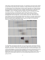
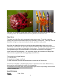
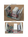
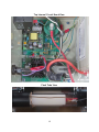
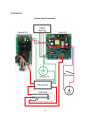
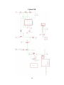
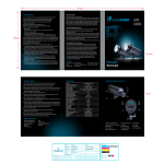
Airgap Flash Manual Version 0.7 October 20, 2013 Lead: Maurice Ribble Major Technical Contributors: Alan Sailer and Paul Picot 1 Table of Contents Safety Description Operation Specifications Maintenance Photos Top View Front View Back View Side View Bottom View Included Capacitor Discharge Stick Included Cables Left Internal View Right Internal View Top Internal View Top Internal Circuit Board View Flash Tube View Schematics System Level Schematic Flyback PCB Pulse PCB 2 Safety DANGER HIGH VOLTAGE High voltage stored in an internal capacitor is LETHAL and may be retained for long periods. To reduce risk of electrical shock disconnect power before opening the case and then the internal capacitor MUST BE DISCHARGED. Never insert anything inside the case. The three terminal power plug on this device makes use of the earth ground connection and that connection must be maintained to avoid electrical shock. Sure the power outlet you are using has a proper earth ground. If you are not knowledgeable about safety procedures for working with high voltage you should never open the case. Instead have it serviced by an expert in high voltage test equipment. If you are familiar with high voltage device safety a capacitor discharge stick is included and you should always discharge the capacitor immediately after opening the case. If the device is ever dropped it should not be turned on until it’s been inspected. This device is designed to operate with a power line voltage of 90 to 132 volts ac, 50 or 60 Hz. A suitable transformertype voltage converter must be used for operation in regions with other line voltages. Never place anything on top of the flash. There are pressure sensitive components inside and the device requires good ventilation. This device has been designed, constructed and inspected with due regard to product safety. However, it does not carry Nationally Recognized Testing Laboratory certification. It is the purchaser's responsibility to determine whether approval is required to use this device in their jurisdiction, and to secure such approval if necessary. The high voltage nature of this device generates ozone. You should use it in a well ventilated area to prevent the buildup of this gas. Description and Background Information This flash is called an Airgap flash because it uses air between two electrodes slightly over an inch apart, and a high voltage to generate a spark. This spark is what generates the flash of light. A photographer can think of it as their own well controlled lightning bolt in a protective case. The Airgap flash is designed to be an extremely high speed flash. That is the problem the Airgap flash solved and it makes compromises in other areas to achieve that goal. For those who want to photograph relatively slow events they should use a normal photography flash. The Airgap flash is for those really high speed events where a normal flash leaves a blurry image. To contrast the Airgap flash with a traditional flash, nearly all photography flash units on the 3 market today use flash tubes filled with xenon gas. The advantage of using xenon gas in flashes is it generates a high quality light with a relatively low voltage (hundreds of volts) and low power. The disadvantage of xenon based flashes is that the reason it generates a lot of light is because the xenon gas glows so these flashes have a relatively long flash duration for super high speed photography. Some of the fastest commonly available xenon flashes have a duration of 1/30,000th of a second. This Airgap flash has a duration of about 1/1,000,000th of a second. This means the duration of the Airgap flash is about 30 times faster which is critical for photographing high speed events such as bullets in flight. Below is an image comparing a photograph taken with this Airgap flash versus a traditional xenon flash. Note that on many xenon flashes the lower the power setting the shorter the duration so I included a medium power setting and the lowest power setting (fastest mode). You can clearly see that for that even for this air rifle pellet the xenon based flashes can not capture the image, but the Airgap flash captures a very sharp image of the bullet in flight. The Airgap flash uses a flash tube filled with “air” gas (ie the gas mixture we breathe) instead of xenon gas. The main advantage of the using air is that it greatly shortens the duration of a flash. Why fill the tube with air? There must be some better gas, right? Actually Harold Edgerton, who is widely acknowledge as a founder of flash photography, did extensive experiments with various gases and found that for high speed flashes using standard “air” is actually one of the best gases because it gives a good compromise of short durations and moderate amount of light. An added benefit is that using air reduces the cost of the manufacturing process so air is a very good gas choice. 4 Here are a two examples of photos taken with an Airgap flash that would not have been nearly as compelling if taken with tradition flash because they would have had motion blur. Operation The typical use of this flash is for photographing high speed events. To do this a camera is typically set to have a long shutter duration (say 5 seconds) in a dark room. The Airgap flash will provide all the light in a very short duration so shutter speed don’t really matter. Most often the Airgap flash will be used with a high speed photography trigger such as the Camera Axe. The Camera Axe has various sensors to determine when a photograph should be taken and then it can trigger the Airgap flash at that instance. From this point on any references to a high speed trigger will just be referred to as a Camera Axe since that is the triggering system tested with the Airgap flash. The Airgap flash triggers like a standard low voltage flash and should be compatible with other triggering systems out there. The controls for the Airgap flash are: 1) An on/off switch 2) A red button to trigger a test flash 3) A BNC connector which has an included cable to connect to the Camera Axe There is also a standard ¼” threaded tripod mount on the bottom of the flash. Make sure any tripod used can safely handle the weight of the Airgap flash. Fire the flash no more than once every 30 seconds to give it time to fully recharge, reduce ozone creation, and keep cool. Specifications Weight: 9 lbs. 15 oz. 5 Dimensions: Input Voltage: Input Current: Light Duration: 6 x 6.6 x 11 inches 90132Vac at 4763 Hz Under 2 Amps ● ● ● ● Time zero to peak: 0.29 microseconds Full width half maximum: 0.55 microseconds Full width 1/3 maximum: 0.86 microseconds Full width, tenth maximum: 2.7 microseconds Light Output: With the diffuser in place, this flash output is 4 stops below a small shoemount flash at 1/16 power. At ISO200, my test exposures required f/6.3 at 50 cm. Its approximate guide number is 10 (feet, ISO200). Recycle time: Recharges fully in under 10 seconds. However, it will can fire every second or less at a less intense flash which would lead to uneven exposures. Robustness testing was done with 10 second recharge rate so it is recommended to fire the flash at no more than once every 10 seconds. Ground leakage: 68 uA, which is well within safe limits. In the case of an open ground the case potential is 58 Vac, which could be felt but is not dangerous. Trigger lag: In 26 test shots the high voltage trigger pulse averaged 3.7 +/ 0.3 microseconds after the input trigger (extremes: 3.08 and 4.55 us). The actual arc followed another 7.3 +/ 2.8 microseconds (extremes: 4.76 and 11.95 us). Measurement precision was 0.04 us. Trigger current: The trigger reliably fired at 0.5 mA current. Short circuit trigger current is 20 mA. Maintenance The Airgap flash requires periodic maintenance of the flash tube. In our testing we found a oxidation build up that started to prevent reliable flashing after around 2000 or more flashes. This number is highly dependent on the environment. Humidity, heat, and air quality play a factor. The image below is an image after 10,000 flashes and it was still working well. Cleaning is necessary when the flash stops working reliably. This can be extra flashes when it shouldn’t be (though this can also be caused by high humidity even with a clean flash tube), or not triggering when it should. The fix is to take apart the flash head and clean it. To do this safely you must understand how to safely work with high voltage. If you don’t know these procedures leave this cleaning to an expert. The Airgap flash maintains a high voltage even when it’s off and unplugged from the wall. You must use the included shorting stick to discharge the large internal capacitor. 6 One issue that has happened in the past is humid weather caused the the airgap to either randomly trigger or continuously trigger. Increasing the gap between the electrodes in the flashtube can help reduce this problem, but in very humid environments this issue can’t be solved. You should target humidity levels of 50% or lower for optimal operation. 7 Photos Top View Front View 8 Back View Side View 9 Bottom View Included Capacitor Discharge Stick 10 Included Cables Left Internal View 11 Right Internal View Top Internal View 12 Top Internal Circuit Board View Flash Tube View 13 Schematics System Level Schematic 14 Flyback PCB 15 Pulse PCB 16