1
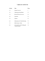
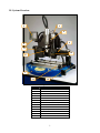
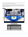
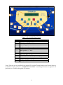
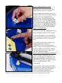
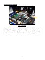
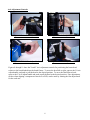
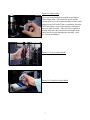
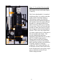
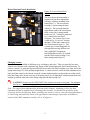
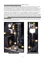
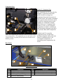
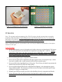
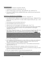
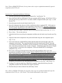
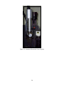
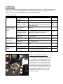
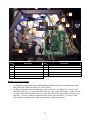
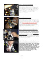
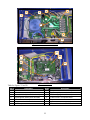
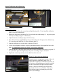
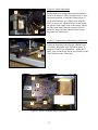
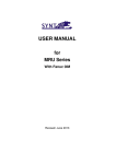
Operation and Maintenance Manual
Rev 2005-08
TABLE OF CONTENTS
Section
Item
Page
1.0
System Overview
1
2.0
Unpacking & Installation
12
3.0
Rework Process Overview
14
4.0
Operation
16
5.0
Options
19
6.0
Maintenance & Troubleshooting
21
7.0
HMI Software Guide
29
8.0
Advanced Rework Profiling and
Control Software
39
1.0 System Overview
5
3
9
2
4
11
12
8
1
10
13
Figure 1: FR-1418
ITEM NO.
DESCRIPTION
1
BASE ASSY
2
BRIDGE ASSY
3
HEAD ASSY WITH REAR ENCLOSURE
4
LCD ADAPTER PLATE
5
LCD MONITOR
6
PC CPU (OPTIONAL)
7
PC MNTR, KBD, TRACKBALL (OPTIONAL)
8
NOZZLE SET STANDARD
9
CAMERA/ZOOM LENS ASSY
10
PCB (BOARD) FIXTURE
11
OPTICS TRAIN
12
MIRROR ASSEMBLY
13
FINE ADJUST MECHANISM
1
The previous picture and table are meant to familiarize the user with the terminology used to describe
the major components of an FR-1418 BGA Rework System.
The figures below describe the specific features and controls found on the FR-1418 BGA Rework
Systems. Not all features and controls will be found on all systems, as they vary according to the
specific model and options purchased. The items described in the following figures will be referred to
throughout the rest of this manual.
Front Panel:
3
4
2
6
1
5
Figure 2: Front Panel Controls
Item
1
2
3
4
5
6
Description
HMI / Operator Keypad w/ LCD
Top (Component) Lighting Intensity Control
Teach Thermocouple Input (TCH or TC1)
Spare Thermocouple Input (TC2)
Bottom (Board) Lighting Intensity Control
Vacuum Switch and Indicator Lamp*
*Note: Some systems may have a footswitch or no switch when controlled by a Host PC.
2
1
3
2
6
11
7
5
4
10
8
12
9
Figure 3: FR-1418 HMI Panel Details
Item
Description
1
LCD Screen / Message Window
2
L.E.D. Status Indicators
3
Vacuum Toggle Switch and Indicator
4
Start Button, or <Start>
5
Stop Button , or <Stop> or <Esc> or <No>
6
Menu Up Button , or <M↑>
7
Menu Button , or <Menu> or <Yes>
8
Menu Down Button, or <M↓>
9
Set Data Up Button , or <S↑>
10
Set Data Button , or <Set> or <Enter> or <Toggle>
11
Set Data Down Button, or <S↓>
12
Bar Graph Progress Indicator
Note: When the unit is controlled by an optional PC with the Thermal Analysis and Control Software
installed, the display will read: “UNDER HOST CONTROL” and all keypad actions are ignored. All
functions are accessible through the PC software.
3
Figure 4: Lighting Intensity Control
Turn clockwise to increase intensity, and
counterclockwise to decrease intensity.
The TOP lighting (left hand knob) affects the
brightness of the video camera image in the UP
direction. This is the COMPONENT or
NOZZLE image. The BTM lighting (right
hand knob) affects the image brightness in the
DOWN direction. This is the BOARD image.
By varying the intensity in both directions, the
operator can view a superimposed image of the
COMPONENT or NOZZLE and BOARD for
installation or removal of SMT components.
Figure 5: Vacuum Control
Vacuum can be manually controlled by a front
panel pushbutton, footswitch, or PC software.
At any time the machine is in a normal RUN
mode, actuating the vacuum switch will toggle
the vacuum from OFF to ON or from ON to
OFF.
The vacuum switch is also used during semiautomatic operation to release the
COMPONENT from the vacuum tip when
placing a component on the BOARD, or when
placing a component in the NEST, to indicate
to the operator that it is time to continue the
cycle after a manual operation.
Figure 6: Thermocouple Inputs (TCH Shown)
The FR-1418 has (2) Thermocouple (T/C)
inputs. The LH input is the TEACH or TCH
input, and the RH input is the SPARE or TC2
input. These are Type K T/C inputs. 36 gauge,
fine wire, Teflon insulated T/Cs are
recommended.
The TCH input is used to measure the solder
joint temperature. The TC2 input can be used
to measure temperature at any point on the
board or component being soldered.
Note: There must be a T/C or jumper plugged into each port in order for the machine to operate in
TEACH or RUN Modes. The system will generate a fault message if either channel is open.
4
Board Fixture and Axis Definition:
4
2
+Z
1
+Y
+X
3
Figure 7: Board Fixture
The standard board fixture consists of front (1) and rear (2) dovetail rails with adjustable spring clips (3)
attached to them. The rear dovetail rail may be adjusted front to back to allow holding boards (also
called PCB or PWB) of varying depths. To adjust the rear rail, loosen the black knobs at both ends, and
slide the rail forward or backward using one hand on each end. Keep the rear rail parallel to the front
rail for easiest adjustment without binding. For convention, left to right on the machine is called the XAxis. The front to back direction is called the Y-Axis. The heater head (4) travels up and down in the
Z-Axis.
5
Axis Adjustment Controls:
Figure 8: X-Axis Fine Adjust Knob
Figure 9: X-Axis Adjust Handle
Figure 10: Y-Axis Fine Adjust Knob
Figure 11: Y-Axis Adjust Handle
Figures 8 through 11 show the X and Y Axis adjustment controls for positioning the heater head
relative to the board loaded into the board fixture. To move the head left or right, squeeze the X-Axis
adjust handle, and push or pull the head to the desired position. To move the head front to back,
squeeze the Y-Axis adjust handle and push or pull the head to the desired position. Fine adjustments,
such as when aligning a component or nozzle to a PCB, can be made by rotating the fine adjust knob
for the each axis.
6
Figure 12: Theta Adjust
The lower heater head can be rotated by turning the
Theta Adjust knob. This rotates the nozzle and the
vacuum pick-up, so the component and/or nozzle can be
aligned to the PCB in the Theta, or rotational, direction.
The Theta adjust is a precision assembly with limited
travel in either direction. Take care not to continue to
turn the knob once the Theta has been adjusted to the
end of travel to avoid damaging the assembly. (Also
see: Nozzle Installation)
Figure 13: Z-Axis Adjust Handle
Figure 14: Z-Axis Fine Adjust Knob
7
Figure 15: Z-Axis Rack Gear Assembly
Adjusting the heater head height (figures
13 and 14):
4
1
7
5
6
3
2
The Z-Axis adjust handle (1) is attached
to the heater head. It is used to select the
rough position of the heater head (7).
This position is either UP or DOWN.
Squeezing the adjust handle disengages a
pin from the Z-Axis fine adjust rack gear
assembly (3), allowing the head to be
lifted or lowered to the top (4) or bottom
(5) travel stop. There is a slot in the rack
assembly at either end of travel in which
the pin engages when the adjust handle is
released. The Z-Axis Fine Adjust Knob
(2) rotates a pinion gear (6), which moves
the rack assembly up or down. This
provides additional up and down
adjustment of the head when it is in either
the UP or DOWN rough position.
During general use the rack assembly
should always be adjusted UP using the
knob, unless the operator is in the process
of picking, placing or soldering a
component. This ensures that there will
be adequate clearance between the heater
nozzle and the board or nest when a rapid
move is made between the UP and
DOWN rough positions.
8
Heater Head and Nozzle Installation:
Figure 16: Lower Heater Head
Details
5
8
4
1
7
2
2
3
6
The lower heater head assembly is
supported by the theta adjustment
bearings, which are mounted to the
heater plate (7). The lower heater
housing (1) rotates using the theta
adjust (8). The heat path from the
upper heater head to the lower heater
head is closed by a spring-loaded
bronze seal (4). Vacuum is generated
by a venturi in the rear head
enclosure. The vacuum tip (6), not
visible in Fig. 16, receives vacuum
through a Teflon tube connected to
the vacuum transfer pipe (5). The
vacuum tips are interchangeable for
placing and removing different size
and weight SMT components.
Interchangeable nozzles (3) are held
into the lower heater housing (1) by
three spring-loaded clips (2).
Changing Nozzles:
Heater nozzles are available in different sizes, end-shapes, and styles. They are generally low-mass
stainless steel shrouds with a machined top flange or hub which engages the lower heater housing. To
remove a nozzle (3), grasp the shroud and tilt the lower end of the nozzle slightly away from one of the
spring loaded clips (2), while pulling straight down. To insert a nozzle, center the theta adjustment (see
note), hold the nozzle by the shroud, insert the vacuum tip through the opening in the top of the nozzle,
place the flange of the nozzle over two of the spring clips (2) at a slight angle, and then push the nozzle
straight up until the other side of the flange snaps past the third spring clip.
CAUTION! Nozzles may be VERY HOT! Hot nozzles can cause severe burns. Use adequate
hand protection when changing a hot nozzle, or wait for the nozzle to cool before changing.
Note: The range of theta adjustment for the heater head is limited. Attempting to force the theta
adjustment beyond its intended travel will damage the assembly. To minimize the possibility of this
occurring, observe the following: Before installing each nozzle it is best to center the theta adjustment in
its travel range and install the nozzle at the approximate rotation angle required for installation or
removal of the SMT component (usually 0, 90, or 45 degrees.)
9
Video Camera and Optical Alignment System: (Figures 17 & 18)
A video/optical system aids the operator in aligning the nozzle or component to the board. To use the
alignment system, put the head in the UP position, and slide the optics train (10) to its right-most
position underneath the nozzle. Top lighting (1) illuminates the component and/or the end of the nozzle
and vacuum tip. Bottom lighting (2) illuminates the board. Light reflected from the component and
board travels through the beam-splitting prism (3), reflects off the flat mirror (4), into the zoom lens (9),
and finally onto the CCD imaging device (8). The CCD imaging device transmits a video signal to an
LCD flat screen, an analog monitor, or a PC for high magnification viewing of the superimposed
component/board image. The intensity of the component or board image can be adjusted by varying the
light intensity. The image is adjusted using the focus (5), zoom (6), and f-stop (7) controls on the zoom
lens (9). Always focus the camera on the BOARD and adjust the Z height of the component or nozzle to
focus the top image. When focusing a component, adjust the Z height of the component so that the pitch
of the leads on the component matches the pitch of the in-focus pads on the board. This is easiest when
the X/Y/Theta adjusts are used to set the leads on the component parallel to, and one-half pitch offset in
the Y direction from the pads on the board.
7
8
6
1
5
9
3
4
10
2
4
Figure 18: Camera & Zoom Lens
Figure 17: Optics Components
10
Component Nest:
Figure 19: Component Nest
The component nest (1) is provided for
aligning a component to the heater
nozzle, and for receiving a hot
component after it has been removed
from the board. The system is furnished
with a generic plate (not shown) which
fits into the component nest to aid in
aligning new components with the
heater nozzle (5). Component Print
Frames, or CPF (2), also fit into the
component nest, and are available for
stencil printing solder paste onto BGA
(3) and some other SMT components.
2
1
4
3
5
Note: The component nest and optics train are shown in their
retracted positions. The component nest (1) and optics train
(4) must be fully retracted for the head to be lowered to the
DOWN position.
With the head UP, extend the
component nest to its right-most
position to align the center of the nest
insert (2) with the nozzle (5) for
receiving hot components, or
transferring a new component to the
nozzle.
Rear Panel:
4
1
5
6
3
2
7
Figure 20: Rear Panel
Item
1
2
3
4
Description
Rear Panel
On/Off Switch (Power Switch)
Air/N2 Supply Inlet (1/4” Tubing)
Services to Head Assembly
Item
5
6
7
11
Description
Serial Number Decal
Host PC and/or Options Connector(s)
Power Cord
2.0 Unpacking and Installation:
The rework system packaging may vary due to the specific model purchased, options installed, and
shipping/transportation requirements. The following figures provide a general guide for unpacking the
system.
2
2
1
6
5
8
7
3
4
Figure 21: Outer cardboard or crating removed
9
Figure 22: Bracing and Plastic Removed
To unpack the machine:
Remove the outer cardboard or wooden crating material. Remove the two 5/16 lag bolts (2), and the
hold-down brace (1) from the cushioned skid (4). Remove the outer plastic sheeting, shrink wrap or
optional vapor-barrier bag (3). Remove the nozzle kit (5), accessory pack (6), and any LCD monitor (7)
and/or optional equipment. The machine can now be lifted off the skid using at least two people. The
uncrated machine weighs approximately 140 pounds. Place the machine on a stable bench with a solid
top. The bench should not wobble or bend under the weight of the machine. If necessary adjust the four
leveling feet so that the machine sits flat on the bench without rocking. Remove any final shrink wrap,
plastic or foam, except the foam block (8) under the head. Raise the head to remove the final foam
block. Remove the cardboard (9) covering the bottom heater.
Y-Axis
Figures 22 & 23: Axes Blocked
1
1
1
1
X-Axis
12
Stop Collars (1) are used to
secure the axes for shipment.
Loosen the #10-32 set screws
and slide the collars out of the
way.
Power and Air/N2 Connections:
Connect air or nitrogen to the rear panel fitting using ¼ inch plastic tubing. (See Fig. 20 on page 11) The
supply gas must be clean, dry and regulated to 60PSI. The supply should be capable of delivering 5
CFM minimum continuous supply at 80 PSI. Poor filtration or wet air lines will degrade heater and
pneumatic component performance.
Plug the power cord into an appropriate, dedicated 120VAC outlet. It is now safe to turn on the power
to the machine. The machine will run through a brief self-check on power-up and then be ready for
operation. See section 4.0 Operation and Programming, Section 7.0 HMI Software guide, or Section 8.0
Thermal Analysis and Control Software for more information.
Repackaging the system:
Reverse the unpacking procedure, taking special care to secure all moving parts as indicated.
Note: The minimum packaging for local delivery or relocating of systems requires that the machine be
securely fastened to a cushioned skid, with the head blocked, axes locked, bottom heater covered, and
system shrink-wrapped as described in this section.
13
3.0 Process Overview
This section is intended to provide a brief and general overview of the SMT rework process using the
FR-1418. Your process and corresponding requirements may vary considerably.
The typical rework process using this equipment would include the following three phases, each of
which has several steps.
Rework Phases
I.
Component Removal
II.
Board and Component Preparation for Installation
III.
Component Installation
Rework Phase I - Component Removal
Typical steps:
1. Load the board with the component to be removed in the board fixture.(Fig. 7)
2. Align the nozzle with the component using the video image and X/Y/Theta adjust knobs
(Fig. 8-12, 17, 18)
3. Retract Optics and lower head near board (Fig. 13-15)
4. Press <Start> to initiate the RUN/REMOVE Heat Cycle (Fig. 3, Section 4.0, Section 7.0)
5. When the heat cycle is complete, the vacuum comes on. Adjust Z height to pick up the component (Fig.
14)
6. Raise heater head (Fig. 13-15)
7. Move the component nest/CPF under the hot component (Fig. 19)
8. Lower the head near the component nest and press the VAC switch to drop the component and continue
the cycle.
9. After a timed cooling step, the cycle is complete.
10. Retract the component nest and raise the head. (Fig. 19, 14)
Note: See the items referenced after each step for additional information in this manual.
Rework Phase II - Board and Component Preparation
Practices vary widely, but they may consist of the following steps:
1. Remove excess solder and level the pads with solder wick and soldering iron (Fig. 24 & 25)
2. Print fresh solder paste onto BGA balls using CPF stencil (Fig. 26) Note: In many cases for plastic BGA
components with eutectic solder balls, a thin coating of flux paste is applied to the board in lieu of adding
additional solder paste.
3. Load CPF with BGA into component nest (Fig. 19)
14
Rework Phase III – Component Installation typically consists of the following steps:
1. Load PCB onto adjustable board fixture (Fig. 7)
2. With the head UP, load the component in the nest and slide it under the nozzle (Fig. 13-15, 19)
3. Press <Start> to initiate the RUN/INSTALL cycle. The vacuum turns on. (Fig. 3, Section 4.0, Section
7.0)
4. Adjust the head Z height down to pick up the component and then up away from the nest (Fig. 15)
5. Retract the nest and extend the optics train under the nozzle with the component (Fig. 19)
6. Using the video image and X/Y/Theta adjustments, align the leads (balls) on the component to the pads
on the PCB (Fig. 8-12, 17, 18, 27, Section 4.0)
7. Retract the optics train, move the head DOWN to the board. (Fig. 19, 13-15)
8. Adjust the Z height so the component is just touching the board (Fig. 15)
9. Press the VAC button or footswitch to release the component and continue the cycle (Fig. 3)
10. Adjust the Z height so the nozzle is approximately 1/8 inch above the top of the component (Fig. 15)
11. The cycle continues heating through Preheat (PH), Soak (SK) and Reflow (RF) steps. (Section 7.0)
12. The cycle progresses to the Cooling (CL) step, while air flows through the heater nozzle to freeze the
solder joints. The cycle is complete. (Section 7.0)
13. When the board has cooled sufficiently, remove it from the board fixture (Fig. 7)
14. Proceed to electrical test, visual inspection, or x-ray inspection of the reworked assembly as required
Figure 24: Removing Excess Solder
Figure 25: Leveling Pads using Solder Wick & Flux
15
Balls
Pads
Figure 26: Printing BGA with Solder Paste
Figure 27: Aligning the Component
4.0 Operation
Note: The operation and programming of the FR-1418 requires that the operator have reasonable
proficiency with the features, controls and processes described in Sections 1.0, 3.0, 7.0, and 8.0 (if
applicable) of this manual. Read and understand sections 1.0, 3.0, 7.0, and 8.0 (if applicable) before
proceeding to operate and program the equipment as described in this section.
Note: Consult the references in parentheses after each item for additional information or description
relevant to each topic.
General Warnings:
1. Keep in mind that the system is designed to melt solder joints on very dense boards. The heaters
are very powerful and can reach internal air temperatures exceeding 450° C (840° F). Surfaces
of the heater, PCB, nozzle, and other components can be VERY HOT. Always use caution to
prevent accidental burns, especially when changing nozzles, unloading boards or components, or
when working around the heater head area.
2. Never touch any glass optics components with bare hands.
3. Never wipe any glass optics components with rags or paper towels. Use an optical wipe, camera
lens tissue, eyeglass wipe, or other material which will not scratch the glass.
4. Never touch the sides (unpolished faces) of the prism. The oil from your hands can penetrate the
bonded seam and adversely affect the image quality.
5. Never touch the halogen bulbs for the component/board lighting, or the bottom heater quartz
lamps with bare hands. The oils from your skin can cause hot spots on the bulbs/quartz lamps,
resulting in cracking or coating failure.
6. Maintain good ESD prevention procedures when handling electronic components and boards.
7. Always disconnect the unit from the electrical and pneumatic supplies before servicing or
maintenance.
16
Powering the System:
1. Check that air/N2 and power are properly connected.
2. Turn the power switch to the 1 (On) position. (Fig. 20)
3. Observe startup messages on LCD screen. Wait for READY. (Fig. 3 and Section 7.0)
4. The system is in INSTALL/RUN or REMOVE/RUN mode, with the last-used recipe loaded in
memory. (Section 7.0)
Operation for Component Removal (Desoldering):
1. Load the desired Recipe using the MENU buttons (Fig. 3 and Section 7.0)
2. Select REMOVE/RUN or REMOVE/TCH mode using the MENU buttons. If REMOVE/TCH is
selected, place the tip of the TCH T/C in contact with the component solder joint. (Fig. 3, 6, and
Section 7.0)
3. Insert the proper nozzle into the heater head (Fig. 16)
4. Insert the standard nest plate into the nest (Fig. 19)
5. Align the nozzle to the board using the video alignment optics. (Fig. 17, 18)
6. Lower the head to the rough DOWN position and then adjust the nozzle height to approximately
1/8 inch above the component to be removed. The nozzle should NOT be touching the
component. (Fig. 13-15)
7. Press <Start> to initiate the heating cycle. The system will progress through Preheat (PH), Soak
(SK) and Reflow (RF) steps at the programmed top and bottom heater settings. When in
REMOVE/RUN mode, the system will run at the programmed step heater settings for the step
times programmed in the recipe. (This is a time-driven cycle.) When in REMOVE/TCH mode,
the system will heat at the programmed step heater settings until the TGT temperature is reached
by the TCH T/C. (This is a temperature driven cycle, and is dependent on T/C feedback. Make
sure the T/C is securely in contact with the solder joint to ensure accurate temperature readings.)
An L.E.D. bar graph progressively illuminates from bottom to top, indicating progress through
the cycle (Fig. 3 and Section 7.0)
8. At the completion of the RF heating time, the vacuum will turn on, and the system will begin to
beep. Adjust the Z height (Fig. 15) to bring the vacuum tip in contact with the top of the
component, and allow the vacuum to engage the component.
9. Adjust the Z height back away from the board at least 1/2 inch, and then raise the head to the
rough UP position. (Fig. 15)
10. Slide the component nest under the hot component, and lower the head near it. (Fig. 19)
11. Press the VAC button to release the component from the tip, and initiate the Cooling (CL) timed
step, then retract the head away from the nest.
12. The cycle is complete when the CL timer reaches the programmed value.
Note: Once the vacuum turns on at the completion of the RF recipe step, the operator has 20 seconds to
remove the component from the board and place it in the nest (Steps 8 through 11, above.) If the VAC
button is not pushed within 20 seconds, the system will go into an alarm fault mode and terminate the
run to prevent accidental board overheating.
17
Note: When in REMOVE/TCH mode, the step times in the recipe are updated automatically upon the
completion of the TCH cycle.
Operation for Component Installation (Soldering):
1. Load the desired Recipe using the MENU buttons (Fig. 3 and Section 7.0)
2. Select INSTALL/RUN or INSTALL/TCH mode using the MENU buttons. If INSTALL/TCH is
selected, place the tip of the TCH T/C in contact with the component solder joint. (Fig. 3, 6, and
Section 7.0)
3. Insert the proper nozzle into the heater head (Fig. 16)
4. Insert the component into the nest with the standard nest plate or optional CPF. Solder paste or
flux paste may be pre-applied to some components when using a CPF. Orient the component to
meet any polarity requirements for the PCB assembly. (Fig. 19, Section 3.0)
5. With the head in the rough UP position, slide the nest under the heater nozzle (Fig. 19, 13-15)
6. Press <Start>. The vacuum turns on.
7. Adjust the head down to pick up the component, and then raise the head away from the nest (Fig.
15)
8. Align the leads on the component to the pads on the board using the video alignment optics.
(Fig. 17, 18)
9. Lower the head to the rough DOWN position and then adjust the nozzle height to place the
component on the board. The component should touch, but not push on the board. Press the
VAC button or footswitch. The heaters will turn on and the cycle will continue with the PH step
after a short delay which allows the vacuum to dissipate. Immediately adjust the nozzle Z height
to approximately 1/8 inch above the component. The nozzle should NOT be touching the
component. (Fig. 13-15)
10. The system will progress through Preheat (PH), Soak (SK) and Reflow (RF) steps at the
programmed top and bottom heater settings. When in INSTALL/RUN mode, the system will run
at the programmed heater settings for the step times programmed in the recipe. (This is a timedriven cycle.) When in INSTALL/TCH mode, the system will heat at the programmed step
heater settings until the TGT temperature is reached by the TCH T/C. (This is a temperature
driven cycle, and is dependent on T/C feedback. Make sure the T/C is securely in contact with
the solder joint to ensure accurate temperature readings.) An L.E.D. bar graph progressively
illuminates from bottom to top, indicating progress through the cycle (Fig. 3 and Section 7.0)
11. Cooling (CL) is the last timed step. When this is complete, adjust the head away from the
component, and then raise the head to the rough UP position.
12. The board may be removed when it has sufficiently cooled.
Note: When in INSTALL/TCH mode, the step times in the recipe are updated automatically upon the
completion of the TCH cycle. (See Section 7.0 for detailed information on the recipe.)
18
5.0 Options
A variety of nozzles, vacuum tips, accessories and factory installed options are available to meet the
needs of different rework applications. Consult your sales representative for the most up-to-date
information on accessories and options. Some major system options are briefly described below.
Additional operation and maintenance supplements to this manual may be supplied with some options.
Major System Options:
1. Two-Zone Bottom Heater – This option provides a second, 10 x 12 inch bottom infrared heating
zone which can be turned on or off in any heating step of each recipe. The total bottom heat area
with this option installed is 12 inches in the Y direction and 20 inches in the X direction. The
left-hand zone is Zone 1 in the recipe, while the right-hand zone is Zone 2.
Figure 28: Two-Zone Bottom Heater Option
2. Thermal Analysis and Control Software – An advanced software control and temperature
profiling software package is available that allows the rework system to be controlled by a
Pentium™ class PC with its serial port connected to the HOST PC connector (Fig. 20) on the
machine’s rear panel. This software also allows the recipes to be created and stored on the PC.
Thermocouple data can be plotted real-time, stored, and analyzed using software tools for
measuring ramp rates, time above melting temperature, and more. The customer can purchase
software only, and provide their own PC, or the software can be preinstalled on a PC with a
frame-grabber card for viewing the video camera images using a 15 inch or 17 inch PC monitor.
(This option may not currently be available for all models.)
3. Automatic Motorized Z Axis – This option is only available if option 2, above, is installed. It is
only available as a factory-installed option. The Heater head is driven by a motorized lead
screw, making the Z-Axis of the machine automatic. This allows more automated rework cycle
operation, with the pick-and-place operations programmed into the recipes, and controlled by the
PC software. (This option may not currently be available for all models.)
19
Figure 29: Automatic Motorized Z-Axis Option
20
6.0 Maintenance and Troubleshooting
Important: Always disconnect the unit from the electrical and pneumatic supplies before servicing or
performing maintenance.
Maintenance:
Linear Bearing Rails
All linear bearing rails should be cleaned once a month with a tack rag to remove debris, dust and dirt
from the rails. A Medium lubricant such as Way Oil should be applied to the X-Y and Z rails/linear
bearing rails once every three months. At the factory, we use Mobil Vactra™ #2 (ISO 68) Medium Way
Oil.
Bottom Heater
IMPORTANT: NEVER TOUCH THE HEATER LAMPS WITH BARE HANDS!
The bottom heater should be cleaned of dust and debris as needed. If large amounts of dust and debris
accumulate inside the bottom heater, remove the top cover and collimator grille, vacuum the interior,
and clean the reflectors and bulbs with isopropyl alcohol and a wipe.
Prism & Mirror
IMPORTANT: NEVER TOUCH THE PRISM OR MIRROR WITH BARE HANDS!
Natural oils from your skin may cause permanent damage to the surfaces or bond interfaces.
The prism and mirror should be cleaned once (1) a month with a non-abrasive tissue. Lens cleaner
(preferred) or isopropyl alcohol can be added to the tissue to remove difficult or heavy deposits. If
alcohol is used however, a second pass with a dry non-abrasive tissue is recommended to remove any
haze. At the factory we use Bausch & Lomb Sight Savers® #8566.
IMPORTANT: NEVER LEAVE THE COMPONENT/BOARD LIGHTING ON FOR AN
EXTENDED PERIOD OF TIME OR WHILE THE SYSTEM IS UNATTENDED!
Excessive heat from the halogen lighting system can damage the bond interfaces of the prism.
Vision Calibration
The vision system on the machine should be verified and/or calibrated annually. This is completed
using the Calibration Kit included with the machine. A detailed procedure is explained below.
Z-Axis Lead Screw Shaft (for systems with Motorized Z-Axis)
This should be lubricated once (1) every six months. Manually drive the top heater head down to the
bottom home position, then turn the Power OFF. The shaft should be lubricated with a heavy grease
which will not melt or run at moderate temperatures, preferably a Lithium Grease compound (12Hydroxy Lithium Complex). At the factory we use StaPlex Premium E.P.. Restore power, and “Home”
Z-Axis.
Other
The machine should be kept clean to prevent build up of flux or other substances or objects that may
degrade performance or damage the machine.
21
Troubleshooting:
Below is a general guide for troubleshooting certain operational problems. Consult a qualified service
technician if you do not understand basic troubleshooting techniques, or if the problem can not be
identified and corrected using the information provided in this manual.
Troubleshooting table:
Symptom
Weak vacuum at tip
Component is not
placed accurately
compared to video
image
Bottom heater does
not turn on as
programmed
Component or board
lighting does not
work
Vacuum tip not
centered in video
window
Possible Cause
Worn or damaged
vacuum cup
Leaking vacuum
system
Insufficient supply
pressure or volume
Improper Z height
when vacuum is
turned off
Component sticks to
vacuum cup and then
drops back to board
inaccurately
Optical calibration is
inaccurate
A quartz lamp is burnt
out
A short circuit caused
a blown fuse
A halogen bulb is
burnt out
Optics train stop
requires adjustment
Flat mirror requires
adjustment
References
Fig. 29
Find and repair leaks in the vacuum system
Fig. 29, 30
Increase supply pressure above 60 PSI. Check
supply capacity meets CFM requirements and
check supply tubing.
Review Section 4.0 for proper placement
technique.
Fig. 20
Section 2.0
Clean vacuum tip, use a different size vacuum
tip, or modify Z height used when placing and
releasing the component on the board.
Verify and/or re-calibrate according to the
procedure below.
Inspect the lamp filaments. Replace burnt-out
lamps
Find and correct the cause of the short circuit,
then replace the fuse.
Inspect the bulb filaments. Replace burnt-out
bulbs
Check and/or adjust the optics train stop as
described in the optical calibration procedure
Check and/or adjust the flat mirror as described
in the optical calibration procedure
Section 4.0
Section 4.0
Fig. 29
Fig. 33, 34
Fig. 31, 32
Fig. 35
Fig. 36
Figure 29: Vacuum Pick-Up System
5
4
3
6
Corrective Action
Replace the vacuum cup
1
2
Interchangeable vacuum tips (1), which may
or may not have a silicone vacuum cup (2),
are screwed into the vacuum stem (3) with
#10-32 threads. The vacuum transfer tube
(4) pipes the vacuum from the tubing (5) to
through the lower heater housing (6) to the
stem. A vacuum generator (Item 2, Fig. 30),
generates the vacuum pressure. A leak
anywhere in this system may cause weak
vacuum at the tip.
22
1
2
9
7
8
3
4
5
10
11
6
Figure 30: Rear Head Enclosure Details
Item
1
2
3
4
5
6
Description
Rear head enclosure
Vacuum generator
Medium air flow solenoid valve
Low air flow solenoid valve
Vacuum generator feed solenoid valve
Air pressure switch
Item
7
8
9
10
11
Description
Low air flow control needle valve
Head distribution/dimmer board
Heater power connections
Heater T/C connection
Ground connections
Routine Service Procedures:
1. To change the component or board lighting halogen bulbs found on the standard optics train,
follow the steps outlined in Figures 31 and 32, below.
2. To change the bottom heater quartz lamps, remove the base cover plate (Fig. 7, Item 5) and
collimator grille (Fig. 7, Item 6), and then follow the steps outlined in Figures 33 and 34, below.
3. To replace fuses, first find and correct the cause of the blown fuse, then remove the base cover
plate (Fig. 7, Item 5), locate the appropriate fuse on the power board (Fig. 35, Item 3), and
replace the fuse with one of the same type and rating. Reinstall the cover.
23
Figure 31: Removing the lighting cover
Remove the four corner screws (1) securing the top or
bottom lighting cover (2) as required. Carefully pull
the cover straight out of the housing (3) with the bulb
mount (4) still attached. See Fig. 32, replacement
bulbs must be of the exact type as the original
equipment (75 W Max.)
1
2
1
3
Figure 32: Changing halogen bulbs
5
4
6
Pull the bulb (5) straight out of the socket (6) and insert
the new bulb in the reverse fashion. It may be necessary
to slightly bend the contact pins on the new bulb to fit the
socket. Do not touch the bulbs with bare hands. Be
sure to observe the handling warning stated at the
beginning of this section. Take care not to pinch the
supply wires (7) when replacing the cover.
7
1
2
Figure 33: Replacing the bottom heater quartz lamps
Grasp the lamp (1) near one end. Push slightly towards
the opposite contact block (2), then tilt the lamp up and
out of the heater assembly as shown. Do not touch the
bulbs with bare hands. Be sure to observe the handling
warning stated at the beginning of this section. Insert the
new lamp in the reverse manner.
Figure 34: Checking the bottom heater lamp contacts
Grasp the lamp (1) near the center. Push the lamp slightly
toward one contact block (2), then the other. You should
feel some movement in each direction as the contact
springs flex. The lamp should not rattle or feel loose. The
lamp should be supported only by the pins in the contact
blocks. Rotate the lamp a small amount, in both
directions, about its long axis to feel that the bulb is
securely seated on the contact pins.
24
7
4
5
3
1
6
2
8
Figure 35: Power Distribution Board
9
12
10
13
11
14
Figure 36: I/O Board
Table for Figures 35 and 36:
Item
1
2
3
4
5
6
7
Description
Power distribution board
I/O board
Fuses (Individually identified on board)
Top and bottom heater power terminals
Optional Zone-2 heater power terminals
Power control module electrical connections
12 VDC output connector
Item
8
9
10
11
12
13
14
25
Description
Main power connections to/from power switch
Thermocouple input terminals
CPU board (plugs into I/O board)
12 and 24 VAC from power board
Output connector
Input connector
Ribbon cable to front LCD HMI Panel
Optical Calibration and Adjustments:
3
1
2
Figure 37: Calibration Plate
Figure 38: Calibration Tip
Calibration Procedure:
1. Remove the covers from the camera lens and light housing (Fig. 17) and install the calibration
plate (1) onto the board support.
2. Remove the nozzle and vacuum tip (Fig. 29) and install the calibration tip (2). Adjust the optics
train stop according to Figure 39 if necessary.
3. Adjust the mirror according to Figure 40 if necessary.
4. Move the head to the rough DOWN position and then adjust the Z height so the calibration tip
(2) is just above the blind hole (3) in the calibration plate (1).
5. Align the calibration tip with the plate as shown in Figure 41.
6. Use the video alignment system to view the superimposed image of the tip and the hole in the
plate. It is important not to allow the X and Y axes to move at this time.
7. If the tip and hole in the plate appear concentric, then no adjustment of the prism is required. If
the tip and hole appear misaligned, adjust the prism according to Figures 42 and 43.
8. Replace the vacuum tip, and any covers which have been removed.
Figure 39: Optics train stop adjustment
4
Bring the head to its uppermost position. Move the
optics train to the right until it stops (Fig. 17).
Adjust the Z height so the calibration or vacuum tip
is just above the top lighting and visually check that
the tip is centered left to right with respect to the
prism. Gauge the centering of the prism with a
graduated scale, if one is available. If the optics
train position requires adjusting, adjust the stop
screw (4) accordingly.
26
Figure 40: Mirror adjustment
7
Return the head to its uppermost position and turn
on the LCD monitor. Move the optics train (7) to its
right-most position. Loosen the locking screw (5)
on the mirror bracket very slightly and, using the
three set screws (6), adjust the mirror so the nozzle
tip appears in the center of the video image. Adjust
the lens zoom control through its entire travel to
ensure the image remains centered on the screen.
Re-tighten the center screw.
5
6
Figure 41: Aligning the calibration tip with the plate
Adjust the head down and align the calibration tip
(2) with the blind hole in the calibration plate (3)
using the X and Y fine adjustments. Adjust the X
and Y axes so that the tip can be moved easily in and
out of the hole in the Z direction.
2
3
9
8
12
9
11
Figure 42: Prism Left/Right Image Adjustment
27
12
11
10
10
8
Figure 43: Prism Front/Rear Image Adjustment
To Adjust The Prism:
The prism (11) is bonded to an adjustable mount (12), which allows it to be oriented squarely to the ZAxis. This can correct any optical image misalignment observed during the calibration procedure,
above. Do not adjust the prism mount for any reason, unless the above calibration procedure indicates
you should do so. Slightly loosen the three socket head cap screws (8) on the prism bracket. To correct
a left-to-right image misalignment, adjust the set screws (9) to produce the desired effect. To correct a
front-to-back (top-to-bottom on video monitor) image misalignment, adjust the set screws (10) to
produce the desired effect. (Note: When adjusting the set screws, loosen one and tighten the opposite
one.) After accomplishing the alignment of the two images, gently tighten the three socket head cap
screws on the prism bracket. Watch the video image as the screws are tightened to ensure that the
images stay aligned.
28
7.0 HMI Software Guide
FR-1418 FRONT PANEL OPERATION
POWER-ON & RUNNING A RECIPE
--PLEASE WAIT--
First application of power:
AMERICAN HAKKO
REWORK SYSTEM
Unit says:
”American Hakko Rework System”
REV X
Note: The current software revision (X ) is displayed on the right side of the screen.
Unit shows recipe ## is loaded
and ready to run by pushing <START>
(or push <MENU> to get main menu).
RUN INSTALL...
PRESS <START>
## RUN
READY
RUN MODE
PRESS <START>
## RUN
READY
Note: ## indicates recipe # which is ready to run.
MAIN MENU
From the “RUN READY” screen...
push the <MENU> keys to get additional
menu choices:
Note: Mode indicates either install or remove.
Use the MENU UP, MENU DN keys
to navigate from MENU to MENU.
Push <MENU> to select the choice shown.
CHANGE TO MODE?
<^><v> OR <MENU>=YES
Select “CHANGE TO INSTALL OR
REMOVE” screen to toggle between install
and remove modes.
--OR-<STOP> TO EXIT
Note: Mode indicates either install or remove.
LOAD NEW RECIPE ##?
<^><v> OR <MENU>=YES
Select “LOAD NEW RECIPE”
to go to a screen where a new Recipe #
can be chosen.
--OR-<STOP> TO EXIT
29
EDIT/TEACH SETTINGS?
<^><v> OR <MENU>=YES
Select “EDIT/TEACH SETTINGS”
to Edit or Teach a Recipe.
--OR-<STOP> TO EXIT
SETUP/DIAGNOSTICS?
<^><v> OR <MENU>=YES
Select “SETUP/DIAGNOSTICS”
to enter Setup Mode (pgm password)
or run Diagnostics.
--OR-<STOP> TO EXIT
MANUAL MODE?
<^><v> OR <MENU>=YES
Select “MANUAL MODE”
to run the bottom heaters manually.
--OR-<STOP> TO EXIT
RAMP & HOLD MODE?
<^><v> OR <MENU>=YES
Select “RAMP & HOLD MODE”
to control the bottom heaters based
on a desired set point temperature
and an actual thermocouple reading.
--OR-<STOP> TO EXIT
LOADING A NEW RECIPE TO RUN
From MAIN MENU, select “LOAD NEW
RECIPE”. Use the SET UP, SET DN keys
to increment/decrement the recipe #.
Push the <SET> key to accept the choice.
#00=RECIPE NAME
<^><v> OR <SET>=ENTR
Note: The unit holds 100 (#00-#99) recipes in non-volatile memory.
ENTERING THE PASSWORD
Use the SET UP, SET DN keys to enter
the 1st digit of the password and push <SET>
Repeat until all 6 password digits are entered
PASSWORD? (6 DIGITS)
Note: The system default password is 123. You must push <SET> 3 times to serve as the last 3 digits.
30
*PASSWORD INCORRECT*
<MENU> TO TRY AGAIN
If the Password was incorrect, push the
<MENU> key to try again.
--OR-<STOP> TO EXIT
*PASSWORD ACCEPTED*
<v> FOR CHOICES
If the Password was correct, push the
MENU DN key to begin.
--OR-<STOP> TO EXIT
EDITING A RECIPE
From MAIN MENU, select “EDIT/TEACH
SETTINGS” and enter the password
PASSWORD? (6 DIGITS)
When the password is entered & accepted
(see ENTERING THE PASSWORD)
the unit asks if you want to Edit Settings
Push the <MENU> key to say yes.
EDIT SETTINGS?
<^><v> OR <MENU>=YES
--OR-<STOP>=EXIT W/O SAVE
When Editing a recipe, use the MENU UP
and MENU DN keys to skip fields you don’t
want to change. When changing a field, use
SET UP and SET DN to change the value,
then push the <SET> key to enter the value.
EDIT NAME (16 DIGITS)
Edit the recipe name using SET UP, SET DN
keys to change the 1st digit, then push <SET>
Repeat process to enter all 16 digits. All 16
digits must be entered with the <SET> key
31
EDIT HEAT 1 SETTINGS
Note: Manual displays default values.
Note: PH = Preheat
Edit HEAT 1 Top Temp using SET UP,
and SET DN. Push <SET> to enter the value.
PH TOP TEMP =250C
<^><v> OR <SET>=ENTR
Edit HEAT 1 Air Flow using SET UP,
and SET DN. Push <SET> to enter the value.
PH AIR FLOW =MED
<^> OR <SET>=ENTER
Edit HEAT 1 Teach Target using SET UP,
and SET DN. Push <SET> to enter the value.
PH TEACH TRGT=120C
<^><v> OR <SET>=ENTR
Edit HEAT 1 Time using SET UP,
and SET DN. Push <SET> to enter the value.
PH TIME MM:SS 01:30
<^><v> OR <SET>=ENTR
Edit HEAT 1 Zones using SET UP,
and SET DN. Push <SET> to enter the value.
Repeat for both zones.
PH ZONES = 1 2
<^><v> OR <SET>=ENTR
PH HEAT PERCENT 80%
<^><v> OR <SET>=ENTR
Edit HEAT 1 Bottom Heat % using SET UP,
and SET DN. Push <SET> to enter the value.
EDIT HEAT 2 SETTINGS
Note: Manual displays default values.
Note: SK = Soak
Edit HEAT 1 Top Temp using SET UP,
and SET DN. Push <SET> to enter the value.
SK TOP TEMP =300C
<^><v> OR <SET>=ENTR
Edit HEAT 1 Air Flow using SET UP,
and SET DN. Push <SET> to enter the value.
SK AIR FLOW =MED
<^> OR <SET>=ENTER
Edit HEAT 1 Teach Target using SET UP,
and SET DN. Push <SET> to enter the value.
SK TEACH TRGT=175C
<^><v> OR <SET>=ENTR
32
Edit HEAT 1 Time using SET UP,
and SET DN. Push <SET> to enter the value.
SK TIME MM:SS 01:00
<^><v> OR <SET>=ENTR
Edit HEAT 1 Zones using SET UP,
and SET DN. Push <SET> to enter the value.
Repeat for both zones.
SK ZONES = 1 2
<^><v> OR <SET>=ENTR
Edit HEAT 1 Bottom Heat % using SET UP,
and SET DN. Push <SET> to enter the value.
SK HEAT PERCENT 70%
<^><v> OR <SET>=ENTR
EDIT HEAT 3 SETTINGS
Note: Manual displays default values.
Note: RF = Reflow
Edit HEAT 1 Top Temp using SET UP,
and SET DN. Push <SET> to enter the value.
RF TOP TEMP =375C
<^><v> OR <SET>=ENTR
Edit HEAT 1 Air Flow using SET UP,
and SET DN. Push <SET> to enter the value.
RF AIR FLOW =MED
<^> OR <SET>=ENTER
Edit HEAT 1 Teach Target using SET UP,
and SET DN. Push <SET> to enter the value.
RF TEACH TRGT=215C
<^><v> OR <SET>=ENTR
Edit HEAT 1 Time using SET UP,
and SET DN. Push <SET> to enter the value.
RF TIME MM:SS 01:00
<^><v> OR <SET>=ENTR
Edit HEAT 1 zone using SET UP,
and SET DN. Push <SET> to enter the value.
Repeat for all zones.
RF ZONES = 1 2
<^><v> OR <SET>=ENTR
Edit HEAT 1 Bottom Heat % using SET UP,
and SET DN. Push <SET> to enter the value.
RF HEAT PERCENT 60%
<^><v> OR <SET>=ENTR
EDIT COOL 1 SETTINGS
Edit COOL 1 Air Flow using SET UP,
and SET DN. Push <SET> to enter the value.
CL AIR FLOW =LOW
<^> OR <SET>=ENTER
Edit COOL 1 Time using SET UP,
and SET DN. Push <SET> to enter the value.
CL TIME MM:SS 00:30
<^><v> OR <SET>=ENTR
33
When you are done editing, push the <STOP>
key. If you have made any changes, the unit
asks if you want to:
Exit & Save = <MENU> key or...
Exit without Saving = <STOP> key
EXIT & SAVE CHANGES?
<^><v> OR <MENU>=YES
--OR-<STOP>=EXIT W/O SAVE
RUNNING THE RECIPE
Push <START> to run the recipe.
Note: The following screens are displayed as the unit progresses through a cycle.
HEAT 1
T3=XXX T1=XXX
00:00
00:00
01 RUN
HEAT 1
HEAT 1 (alternate screen)
T3=XXX T1=XXX
T2=XXX TCHXXX
01 RUN
00:00
HEAT 2
T3=XXX T1=XXX
00:00
00:00
01 RUN
HEAT 2
HEAT 2 (alternate screen)
T3=XXX T1=XXX
T2=XXX TCHXXX
01 RUN
00:00
HEAT 3
T3=XXX T1=XXX
00:00
00:00
01 RUN
HEAT 3
HEAT 3 (alternate screen)
T3=XXX T1=XXX
T2=XXX TCHXXX
01 RUN
00:00
COOL 1
T3=XXX T1=XXX
00:00
00:00
01 RUN
COOL 1
T3=XXX T1=XXX
T2=XXX
01 RUN
00:00
COOL 1 (alternate screen)
Push any key to exit this screen.
or wait 5 seconds
CYCLE DONE...
ELPSD = 00:00
34
01
TEACHING A RECIPE
From MAIN MENU, select EDIT/TEACH
SETTINGS and enter the password.
PASSWORD? (6 DIGITS)
When the password is entered & accepted
(see ENTERING THE PASSWORD)
the Unit asks if you want to Edit Settings.
Push the MENU DN key to get the teach.
screen.
EDIT SETTINGS?
<^><v> OR <MENU>=YES
--OR-<STOP>=EXIT W/O SAVE
Push <MENU> at the teach screen to
run the Teach Mode. The unit will run
normally except TCH will show on the LCD
instead of RUN, and the times will be taught
based on TCH actual temp reaching Teach
Temp. (see Running A Recipe)
RUN TEACH MODE?
<^><v> OR <MENU>=YES
--OR-<STOP>=EXIT W/O SAVE
When you are done using Teach Mode, push
the <STOP> key. If you have made any
changes, the unit asks if you want to:
Exit & Save = <MENU> key or...
Exit without Saving = <STOP> key
EXIT & SAVE CHANGES?
<^><v> OR <MENU>=YES
--OR-<STOP>=EXIT W/O SAVE
SETUP/DIAGNOSTICS
From MAIN MENU, select
SETUP/DIAGNOSTICS and enter the
password.
PASSWORD? (6 DIGITS)
When the password is entered & accepted
(see ENTERING THE PASSWORD),
the Unit asks if you want System Setup.
Pushing <MENU> from this screen allows
you to program a new password. Push
MENU DN and it asks if you want
diagnostics.
SYSTEM SETUP?
<^><v> OR <MENU>=YES
--OR-<STOP> TO EXIT
DIAGNOSTICS?
<^><v> OR <MENU>=YES
Pushing <MENU> from this screen puts
you into the Diagnostic Mode.
--OR-<STOP> TO EXIT
35
SYSTEM SETUP: (PROGRAMMING A NEW PASSWORD)
Use the SET UP, SET DN keys to select the
1st digit of the new password and push <SET>
to enter it. Repeat until all 6 password digits
are entered.
PGM 6 DIGIT PASSWORD:
After all 6 digits are entered, this screen is
shown. Push <MENU>key to Exit & Save
the new password, or push <STOP>
to Exit without saving.
EXIT & SAVE CHANGES?
<^><v> OR <MENU>=YES
--OR-<STOP>=EXIT W/O SAVE
DIAGNOSTICS
The state of the four input lines can be
viewed on the LCD readout by pushing
<MENU> at this screen.
Or push MENU DN to select next diagnostic
menu choice.
TEST INPUTS?
<^><v> OR <MENU>=YES
The four output lines can be tested
using the LCD readout by pushing
<MENU> at this screen.
Or push MENU DN to select next diagnostic
menu choice.
TEST OUTPUTS?
<^><v> OR <MENU>=YES
The four thermocouple inputs can be tested
using the LCD readout by pushing
<MENU> at this screen.
This is the last diagnostic choice. If you push
MENU DN again, it starts over with inputs.
TEST THERMOCOUPLES?
<^><v> OR <MENU>=YES
--OR-<STOP> TO EXIT
--OR-<STOP> TO EXIT
--OR-<STOP> TO EXIT
TESTING THE INPUTS
The LCD shows the state of the inputs.
Push <STOP> to stop the input testing.
IN0=0
IN3=0
IN1=0
N2=0
<STOP>=EXIT
OUT0=0
OUT3=0
OUT1=0 OUT2=0
<STOP>=EXIT
TESTING THE OUTPUTS
Use the SET UP, & SET DN to move the
cursor to the four outputs shown on the LCD.
Push <MENU> to toggle the output state.
Push <STOP> to stop the input testing.
36
TESTING THE THERMOCOUPLES
XXXC
XXXC
The LCD shows the thermocouple temps.
Push <STOP> to stop the thermocouple testing.
XXXC
XXXC
<STOP>=EXIT
MANUAL MODE
Note: Manual Mode is a bottom heat only mode.
Manual mode runs the bottom heaters
manually. Push <MENU> to manually
change bottom heat parameters.
Push <STOP> to stop Manual Mode.
TCH=XXX TC2=XXX
ZNS=1 2
50%
MANUAL
00:00
ZONES = 1 2
<^><v> OR <SET>=ENTR
Edit bottom heat zones using SET UP,
and SET DN. Push <SET> to enter the value
Repeat for all zones
HEAT PERCENT = 50%
<^><v> OR <SET>=ENTR
Edit bottom heat percent using SET UP,
and SET DN. Push <SET> to enter the value
RAMP & HOLD MODE
Note: Ramp & Hold Mode is a bottom heat only mode.
Ramp & Hold Mode runs the bottom heaters
according to a temperature set point. and TCH
actual. Push <MENU> to adjust the set point
as well as the bottom heat parameters.
Push <STOP> to stop Ramp & Hold Mode.
Alternate display in Ramp & Hold Mode.
Edit bottom heat Zones using SET UP,
and SET DN. Push <SET> to enter the value.
Repeat for all zones
TCH=XXX TC2=XXX
SETPOINT=250C
R_HOLD
00:00
T1=XXX T2=XXX
ZNS=1 2
50%
R_HOLD
00:00
ZONES = 1 2
<^><v> OR <SET>=ENTR
Edit bottom heat percent using SET UP,
and SET DN. Push <SET> to enter the value
(this is the highest percent used)
HEAT PERCENT = 50%
<^><v> OR <SET>=ENTR
Edit bottom heat set point using SET UP,
and SET DN. Push <SET> to enter the value
BOTTOM TEMP =XXXC
<^><v> OR <SET>=ENTR
37
FAULT MODE
If you run the machine with no air pressure,
you will receive this error message. Push
<MENU> to clear the message and try again.
FAULT... NO AIR
<MENU> TO CLR FAULT
38
8.0 Appendix B –Thermal Analysis and Control Software
FR-1418 Software Operation
Note: This Appendix is a supplement to the FR-1418 Operation and Maintenance Manual. Read
about and understand the general machine operation before proceeding.
This operator manual supplement is a guide for operating the FR-1418 Rework Systems using the
Thermal Analysis and Control Software Package. This software is available as an option on the FR1418 Rework Systems. Some features and functions may not be enabled or available depending on the
rework system hardware configuration purchased.
Important functions of the software are:
• Virtually unlimited recipe storage and retrieval using the PC hard disk drive, or a remote network
•
Multi-point thermocouple data acquisition, profiling, and analysis to accurately measure
temperature vs. time curves used in the soldering process. This includes convenient tools to
measure ramp rates, time-above-temperature, and other key indicators relevant to the soldering
process.
•
An easy to use graphical HMI1, for running the rework system using the PC.
•
Programmable, automatic Z-Axis control2 for systems equipped with Motorized Z-Axis.
•
Teach-mode interactive programming for simplified development of accurate and repeatable
soldering profiles.
•
Single screen viewing and editing of all computer-controlled recipe parameters.
•
Advanced, manual controls and optimization tools for experienced users
•
Process recipe and thermal profile documentation and printing.
Notes:
1
Human-Machine Interface
2
Not available on all configurations
Main Screen (Figure 1A/Figure 1B):
39
This is the first screen shown upon starting the software. The bottom area of the screen shows the
temperature profile graphing area, while the upper part of the screen shows the operation buttons, status,
data, timers, recipe name and description.
Figure 1A: FR-1418 Thermal Analysis and Control Software – Main (Run) Screen with standard
Manual Z-Axis
40
Main Screen (Continued):
Figure 1B: FR-1418 Thermal Analysis and Control Software – Main (Run) Screen with optional
Automatic Z-Axis
The following menus are available in the Main Screen:
File -> Open
File -> Save
File -> Save As
File -> Exit
View -> Options
Help -> Contents
Displays a dialog box for opening recipe files
Saves any changes made to the current recipe
Saves the current recipe to a new file name
Exits the program
Displays the Options Screen (discussed below)
Displays the software’s help file
Along the left-hand side are the following buttons:
Home Z-Axis Button
Start Button
Stop Button
Install/Remove Buttons
Moves the Z-axis to its home position and resets its zero location
Starts the currently loaded recipe
Stops a running recipe
Toggles between these two modes of operation
41
Run/Teach Buttons
Toggles between these two modes of operation. In “Run” mode the
software will use recorded times for stage control. In “Teach” mode the
software will monitor the machine’s thermocouples for stage control and
will record the times between stages to be used in “Run” mode
Camera View Button
Opens the Camera View window (discussed below)
Jog Button
Opens the Jog window for moving the Z-Axis
(discussed below)
Manual Control Button
Displays buttons and parameters for manually controlling several of the
machine’s outputs (discussed below)
File Name
The file name of the currently loaded recipe file
Description
A text field of the recipe that can be used to display additional information
about the currently loaded recipe
Edit Recipe Button
This will open the Recipe Setup Screen (discussed below) which is used to
edit the currently loaded recipe or create new recipes
Part Temp., Board Temp., Top Heater Temp., Spare Temp.
These fields show the current and target temperatures of each of the
machine’s thermocouples. They can be checked or unchecked to toggle
their display on the graph
Timers
These fields show timer values for each of the process stages, the total
time, and the time above reflow temperature
42
Recipe Setup Screen (Figure 2A/Figure 2B):
This screen is accessed by clicking on the “Edit Recipe” button on the Main Screen. This screen allows
the operator to set the thermal process requirements and the Z-Axis locations for the recipe. The thermal
cycle starts with the Board Heater settings and runs through the heating and cooling steps to the end of
the process. The small chart in the top-right corner shows a graphical approximation of the Target
Profile as determined by the various settings.
Figure 2A: Recipe Setup Screen with standard Manual Z-Axis
43
Recipe Setup Screen (Continued):
Figure 2B: Recipe Setup Screen with optional Automatic Z-Axis
The following is a description of the various items on this screen.
File Name & Description
Reflow
Part Detect
This is the same information that appears on the Main Screen. The
Description can be edited from here.
The amount of time the Part Thermocouple spends above this temperature
is displayed in the “Above Reflow” field on the Main Screen.
(Auto-Z equipped machines only) This toggles whether or not the vacuum
switch is used to detect when a component is on the tip when picking a
component from the nest (Install Mode) or the board (Remove Mode). If
“Use Vacuum Switch” is selected then the Z-Axis will stop seeking as
soon as the vacuum switch is triggered when picking up a component. If
“Nest/Board Place” is selected the software will ignore the vacuum switch
and use the Nest Place or the Board Place positions from the Z Move
Table to determine how far to seek the Z-Axis when picking up a
component. In either case, the Nest Place and Board Place positions are
always used when placing components.
44
Board Heater Section:
Heat Zones 1 & 2
Board Heater Power
Start Preheat At
Time
These buttons toggle which board heaters are active during the process.
Sets the power from 0 (off) to 100 (full power) during the Board Preheat
Stage.
When running in Teach Mode, once the Board Thermocouple reaches this
temperature the software will advance to the Heat 1 (Preheat) stage. The
time required to reach this temperature will be recorded in the “Time”
field. When running in Run Mode this field will be ignored.
When running in Run Mode, the software will use this time to determine
when to advance to the next stage.
Heat Stage Settings:
The following settings apply to each of the three heat stages (Preheat, Soak, and Reflow).
Part TC Target
Heater Temp
Time
Board Heater Power
Air Flow Rate
Cooling Stage Settings:
Time
Air Flow Rate
When running in Teach Mode, the software will compare the Part
Thermocouple reading to this temperature to determine when to advance
to the next stage. The time required to reach this temperature is recorded
in the “Time” field. In Run Mode, this field will be ignored.
This is the temperature setting for the top heater.
In Run Mode, this field is used by the software to determine when to
advance to the next stage.
The power setting for the board heaters can be set for each stage. The
setting can range from 0 (off) to 100 (full power).
These three buttons control the air flow setting through the top heater for
each stage.
The amount of time spent in the cooling stage.
Sets the air flow setting for the cooling stage.
Z Move Table (Auto-Z equipped machines only)
Each recipe has an independent set of Z-positions. The “Set” button next to each field applies the
current Z location to that field. The “GoTo” button moves the Z-axis to the current setting for that field.
The Jog buttons (opened from the Manual Control button on the Main Screen) can be accessed while the
Recipe Setup screen remains open to help set up the Z Move Table.
Focus
Nest
The height at which the underside of the component is in focus when
performing an alignment.
The height the Z-axis will move to prior to extending the nest in
preparation for picking up or dropping off a component. The height
should be set to accommodate the thickness of the component to avoid
collision with the nest.
45
Nest Place
Preheat, Soak, Reflow
Board
Board Place
When placing a component into the nest (or picking up when “Nest/Board
Place” is selected in the “Part Detect” section) the Z-Axis will slowly seek
to this height with the vacuum turned on. This height is typically set at the
point where the vacuum tip just touches the top of the component to avoid
placing too much load on the component.
Each of these heights controls the position of the Z-axis during each of the
three heating stages.
The Z-axis will move to this height prior to picking up or placing a
component on the board.
When placing a component onto the board (or picking up when
“Nest/Place Board” is selected in the “Part Detect” section) the Z-Axis
will seek to this height with the vacuum turned on. The height should be
set at the point where the vacuum tip just touches the top of the component
to avoid placing too much load on the component.
Camera View Screen (Figure 3):
This window is accessed by clicking on the “Camera View” button in the Main Screen. It is also
automatically opened by the software during the alignment stage. The camera image is seen in the panel
on the right only if the system is equipped with a PC based frame grabber as an option to the standard
LCD monitor.
Figure 3: Camera View Screen
The Camera View Screen has the following elements:
Current Z Position
Jog Z-Axis
Simply displays the current position of the Z-Axis
The “Up” and “Down” buttons can be used to jog the Z-Axis while
viewing the camera image
46
Save Image
Continue & Cancel
Clicking this button will capture the camera view to a JPG file. The file is
named “capture.jpg” and is stored in the application directory. (Frame
grabber equipped systems only.)
Both of these buttons will close the Camera View window. When running
a recipe clicking the “Continue” button will inform the software that you
are finished with alignment and that it can proceed with the rest of the
cycle. The “Cancel” button is used for telling the software to end the
cycle prematurely.
Z-Axis Jog Panel (Figure 4):
Clicking the “Manual Control” button on the Main Screen will show this panel. On systems equipped
with an automatic, motorized Z-axis, this panel allows manual motion of the heater head Z height for
setting the values in the Z Move Table, or for maintenance or manual operating reasons.
Figure 4: Z-Axis Manual Controls
The Z-Axis Jog Panel has the following elements:
Position
Move To
Speed
Up, Down
Display the current position of the Z-Axis
Clicking this button will move the Z-Axis to the position entered into the
adjacent text box.
This controls the speed of the Z-Axis when jogging.
Jogs the Z-Axis up or down at the speed set by the Jog Speed control.
47
Manual Control (Fig.5):
This panel is used for toggling several of the machine’s outputs such as Vacuum and heaters. The
machine can be manually operated by using these controls. (Some fields shown may depend upon
optional equipment.)
Figure 5: Manual Control Panel
Options Panel (Figure 6):
The Options Panel is accessed by clicking on the “View” menu in the Main Screen and selecting
“Options”. From here several configurable options are shown. It is recommended that you consult PMT
or your local representative before changing any of these settings as improper values could allow the
machine to damage itself.
The settings are as follows:
Controller 1 (WRD) COM
Controller 2 (TriPLC) COM
This is the Windows COM port that is connected to the port labeled
“Host PC” or “Controller 1” on the rear of the unit
This is the Windows COM port that is connected to the port labeled
“Option” or “Controller 2” on the rear of the unit.
48
Z Axis CPI
Full Speed IPS
Slow Speed IPS
Seek Speed IPS
Default Jog Speed
Nest Clearance
Set
Optics Clearance
This stands for “Counts Per Inch” and represents the number of
stepper counts per inch of travel on the Z-Axis. This is determined by
hardware and must not be changed.
This is the speed (in Inches Per Second) the Z-Axis moves during fullspeed motions.
This is the speed the Z-Axis moves during slow-speed motions.
The speed the Z-Axis moves during seek motions (picking and
placing).
The speed the Z-Axis moves by default during Jog operations. The
actually jog speed can be adjusted using the “Jog Speed” slider in the
Jog Panel.
This is the height at which the Z-Axis clears the top of the nest plate.
If the Z-Axis is below this height then the software will prevent the
nest from extending and colliding with it. Likewise, if the nest is
already extended and the Z-Axis is commanded to move to a height
below this setting then the software will automatically retract the nest
to avoid collision. However, when jogging, the software does not
check this value.
Sets the value to the current Z-Axis position
This setting’s purpose and functionality is identical to the “Nest
Clearance” but for the Optics assembly.
49
Working with Recipes
Creating a new Recipe:
1.) Click on the “Edit Recipe” button from the Main Screen
2.) Select File>>New and then select a recipe template. (A default recipe template default.rct comes
with the software. You may create your own templates from any recipe using the Save As file
options.)
3.) Edit the recipe parameters as desired.
4.) Save the recipe.
Teaching and Running a Recipe:
1.) Open a recipe and check that the parameters represent the rework profile you want to achieve.
2.) Plug a thermocouple into the left-hand port on the front of the machine and attach the exposed
junction to a solder joint on the component to be “taught.” It plots on the graph as the Part
Thermocouple.
3.) Plug a thermocouple into the right-hand port on the front of the machine and attach the exposed
junction to an area of the circuit board away from the target component. This is the thermocouple
which will be used to control the “Start Preheat at” temperature as specified in the Board Heater
section of the recipe. It plots on the graph as the Board Thermocouple.
4.) Insert the proper nozzle into the machine and align with the target component.
5.) Select Teach and either Install or Remove from the main control screen (Fig. 1). It is
recommended to teach recipes in Install mode, since you can see the effect of the cooling and the
teach thermocouple remain in place at the end of the run, making it easier to make adjustments to
the recipe heating profile.
6.) Run the recipe using the Start button. The system will keep track of the time required to reach
the target temperatures programmed into the recipe. The picture below illustrates the machine
operating in “Teach Mode.”
7.) If satisfied with the results, save the recipe after teaching. If you want to make adjustments to
slow down or speed up heating, etc., Edit the recipe parameters, cool the board down, and reteach the recipe.
8.) When a recipe has been successfully taught and saved, it can be run in Run Mode without
thermocouples. Run Mode will use the Preheat Soak and Reflow times learned in Teach Mode.
50
Figure 7 – Screen capture from system operating in Teach Mode. The graph shows that the part
thermocouple has passed the Preheat Target (PH: 140) and is approaching the Soak Target (SK: 175).
Note that the “Soak” indicator is highlighted bright yellow. This is the active step. The paler colored
steps have already been completed. The Current Stage Time counts up in Teach Mode and down in
Run Mode.
51
28920 Avenue Williams Valencia CA 91355-4182
United States of America
Tel: 661.294.0090 Fax: 661.294.0096
Toll Free: 1.800.88.HAKKO (42556)
www.HakkoUSA.com