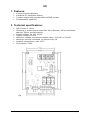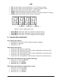
1
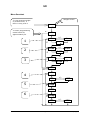
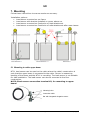
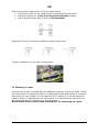
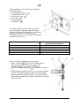
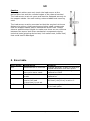
GB MT11 load sensor Bač 49 a, 6253 Knežak, SLOVENIA tel: ++ 386 1 365 80 30 fax: ++ 386 1 365 80 39 email: [email protected] www.sec.si User’s manual GB 1. Features: 4 seven segment displays 4 buttons for parameter setting 3 output relays with programmable NC/NO contact Compensation capability 2. Technical specifications: PCB 100mm x 70mm. Mounting: 4 screw-mount holes with 3mm diameter, 62mm horizontal spacing, 93mm vertical spacing. Supply voltage: 24 VDC ±15%. Supply current:100 mA . Maximum voltage connected to output relay: 120 VAC or 24 VDC. Maximum current connected to output relay: 1A Ambient temperature: max. 45°C IP protection: IP00. Figure 1: MT11 front view with dimensions SEC Electronics MT11 MT11_V2.1 page 2 GB K1: (3-way 5,08 mm terminal block): 24 V DC power supply K2: (4-way 5,08 mm terminal block): measuring sensor input K4: (6-way 5,08 mm terminal block): relay output LED1: green LED (ON when power supply is OK) LED2: red LED (ON when making zero point or LOAD calibration setting) LED3: green LED (BLINK when normal operation) Disp.LED 3 Disp.LED 2 Disp.LED 1 Figure 2: MT11 display LED view Disp.LED 3: ON when Presence exceeds maximal setting Disp.LED 2: ON when Overload exceeds maximal setting Disp.LED 1: ON when Full load exceeds maximal setting 3. Connection terminals: K1 terminal description: terminal 1: 24 V DC (from external power supply) terminal 2: Ground terminal 3: 0V K4 terminal description: terminal terminal terminal terminal terminal terminal 4: 5: 6: 7: 8: 9: R3 R3 R2 R2 R1 R1 Presence common Presence NC or NO contact (depends of programming) Overload common Overload NC or NO contact (depends of programming) Full load common Full load NC or NO contact (depends of programming) K2 terminal description for upper beam mounting: terminal terminal terminal terminal 10: 11: 12: 13: Ground (BLACK) V ref (RED) V + (WHITE) V – (GREEN) K2 terminal description for mounting on ropes: terminal terminal terminal terminal 10: 11: 12: 13: SEC Electronics MT11 Ground (RED) V ref (BLACK) V + (WHITE) V – (GREEN) MT11_V2.1 page 3 GB 4. Operation The load-sensor operation is linear, there for the calibration can be performed with a reference load that is much less than the maximal load. To calculate the curve for load measurements, the MT11 must perform two measurements. First measurement is with reference load and after that with an empty cabin. The whole programming and measuring procedure is listed below. 5. Menu navigation At the beginning, pres “P” to turn the display ON and then hold “P” for 5s, to enter programming mode. The first option is ROUT and is used for setting the output alarm contact. The first parameter is r1no (1) which is Full load with normally open output contact and with + or – button you can set the r1nc which is Full load with normally closed output contact. NOTE: Full load must be set with the maximal cabin load, before you make zero point (4) and calibration (5). The second parameter is r2no (2) which is Overload with normally open output contact and with + or – button you can set the r2nc which is Overload with normally closed output contact. The third parameter is r3no (3) which is Presence with normally open output contact and with + or – button you can set the r3nc which is Presence with normally closed output contact. After you set the ROUT parameters you enter the SET options. Te first option is TARE (4) and is used to make zero point adjustment. With + or – button, you can select YES and then confirm with “P”. After confirming, the measurement will start in 5s! NOTE: Always make zero point, before LOAD (5)! NOTE: Cabin must be empty! SEC Electronics MT11 MT11_V2.1 page 4 GB The second option is LOAD (5) and is used for device calibration. To make the calibration, you must put at least 10% of Full load into the cabin and then input the same known weight in to LOAD. The third option is COMP (6) and is used for compensating false reading, when cabin is empty for 30. To save changed parameters, return to weight screen. If you don’t leave menu, device will after 60s automatically return to weight screen and after 120s display will go off. Buttons “P” button is used for confirming input “E” button is used for escape “UP/+” button is used for moving up in menu or increasing values “DOWN/-” button is used for moving down in menu or decreasing values Figure 3: MT11 display buttons 6. Programming 1. Start the programming procedure, with setting the r1no/nc(Full load), because with this parameter, you set the maximum weight for the cabin, without it you can’t make the calibration. 2. Set the empty lift in to the middle of the shaft and make zero point, with TARE(4) parameter. 3. Load cabin with a known weight and input that weight in to parameter LOAD(5). Pres button P to start the calibration. 4. When the calibration was successful, you will be prompted to parameter CALIBRATION. If you want to use calibration, the weight device will compensate every weight if different of 0, if the lift was stationary for 30min. 5. We recommend that COMP is set to 1. SEC Electronics MT11 MT11_V2.1 page 5 GB Menu flowchart Weight screen To view present weight or present error, if there is one, pres P. 0000 P To enter programming mode hold P for approximately 5s. E 1 rOUt P E 2 E 3 E r2no P r3no P E 6 E +/0000 P +/0000 P +/- r2nc P r3nc P YES P NO lOAd P 0000 P NO COmP E P NO P NO SEC Electronics MT11 0000 P r1nc P tArE P NO P 5 +/- SEt P E 4 r1no P MT11_V2.1 +/- YES P NO page 6 GB 7. Mounting Follow these instructions to ensure maximum accuracy. Installation options: Load-sensor mounted on car frame Load-sensor with bracket installed on ropes, above car Load-sensor mounted on fixed point of rope attachment Load-sensor mounted on fixed point of rope attachment after rope clamps 5.1 Mounting to cabin upper beam MT11 load-sensor can be used on the cabin where the cabin's construction is such that the upper beam is connected to the cabin. Sensor is measuring bending of the beam and the MT11 is recording. The load-sensor is not suitable for side installation. The load-sensor can also be mounted to the floor construction. NOTE: Check sensor connection terminal K2, for mounting to upper beam! Mounting holes Connection cable Bar with integrated elongation sensor SEC Electronics MT11 MT11_V2.1 page 7 GB How to mount the load sensor on to the upper beam: The sensor must not be mechanically stressed before mounting Install the sensor on a flat, free of grease and paint surface Use 4 supplied bolts with 4 nuts and flat washers Example of sensor mounting to different upper beam type: Typical installation on the cabin construction: 5.2 Mounting to ropes Load-sensor can be mounted with an additional bracket, directly to ropes, where the rope tension is measured. With 1:1 attachments the load-sensor is mounted above the car rope clamps. In this case the MT11 device is in the car electrical cabinet. With n:1 attachments the load device is mounted at the fixed point of the ropes and the MT11 device is in the controller. NOTE: Check sensor connection terminal K2, for mounting on ropes! SEC Electronics MT11 MT11_V2.1 page 8 GB The bracket for rope mounting consists of these elements: 1 integrated sensor 1 deformation bar 2 bolt M16 x 80 4 nut M16 2 spacer 20 washers The spacers are the proper length for only one type of support cable diameter and according to the diameter you will add washers in between the spacer and deformation bar .The number of washers is listed in the Table1. Rope diameter 6 mm 8 mm 10 mm 12 mm 16 mm Number of washers/ total length of washers and spacer 0 washers / 41 mm 2 washers / 43 mm 4 washers / 45 mm 6 washers / 47 mm 10 washers / 49 mm Table1 How to install the bracket to the ropes: Place a washer on a bolt and install them through the holes. Slide the spacer and washers(Table1) on to the both bolts. Mount the deformation bar and bolts to secure it. Align bracket parallel to the car or the sealing and evenly space the support cables on the bracket. Fasten the deformation bar by turning both bolts alternatively against the spacer sleeves and secure with the nuts. SEC Electronics MT11 MT11_V2.1 page 9 GB Caution The support cables must only touch the load sensor at the deformation bar and the rounded edges of the channel section! The load sensor must not move and must be fastened securely to the support cables. Use self-locking nuts and additional securing nuts! The load sensor must be mounted so that the required minimum distance to pulleys, shaft openings and other shaft components that the support cables pass is maintained at all times. Please observe possible step heights to make sure there are no collisions between the sensor and other mechanical components during technical tests (gripping device test, limit switch test, buffer test) that could lead to damages! 8. Error table Error name Err1 Explanation Measurement is incorrect Err2 No LOAD calibration and zero point were made No LOAD calibration was made Load is not 10% of full load or full load (r1nc/r1no) is not set Calibration failed Err3 Err4 Err5 SEC Electronics MT11 Solution Change terminal 10 and 11 wire and repeat calibration and zero point. First make zero point setting then calibration LOAD Set all the parameters, make LOAD calibration Set more weight for load or check if full load (r1nc/r1no) is set to 0. Set more weight in to the cabin and in to load option MT11_V2.1 page 10