1
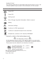
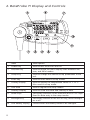
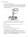
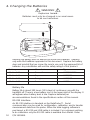
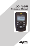
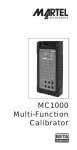
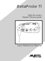
BetaProbe TI
High Accuracy
Digital Thermometer
User Reference Manual
1. Introduction
The BetaProbe TI is designed to be a high precision digital thermometer
that can be used in place of mercury liquid in glass (LIG) thermometers.
It can also be used as a reference standard to check the accuracy of
other types of digital or analog thermometers. Because of its intrinsically
safe certification it can be used in many of the same hazardous locations
as analog thermometers.
The long stem 3/16" diameter probe houses a fast responding thin film
sensor that allows very accurate readings to be taken quickly and with
minimal insertion depth.
A rotatable probe mount allows for both horizontal and vertical
orientation of the display module.
A unique feature of the BetaProbe TI are the trend indication arrows
which the user can configure to show when the readings are considered
to be stable enough to record the reading.
Additional features such as min/max storage, selectable sample rate,
auto-shutoff, backlight and damping allow the user to tailor the TI for their
specific application.
Battery life is up to 300 hours. With the auto-shutoff feature the typical
user may only have to change the batteries a few times per year.
1.1 Customer Service
Corporate Office:
www.martelcalibrators.com
e-mail: [email protected]
Tel: (603) 434-1433
800-821-0023
Fax: (603) 434-1653
Martel Electronics
3 Corporate Park Drive
Derry, NH 03038
1.2 Standard Equipment
Check that your BetaProbe TI has arrived intact. Batteries are factory
installed. Save the packing materials at least until you have verified that
there is no concealed damage.
1.3 Safety information
A Warning identifies conditions and actions that pose hazard(s) to the
user; a Caution identifies conditions and actions that may damage the
Calibrator or the equipment under test.
1
Symbols Used
The following table lists the International Electrical Symbols. Some or all
of these symbols may be used on the instrument or in this manual.
Symbol
Description
Power OFF
Power ON
Earth ground
Risk of Danger. Important information. Refer to manual.
Battery
Hazardous Voltage
Conforms to ATEX requirements
Conforms to relevant European Union directives.
Wheeled bin, conforms to EC directive 2002/96/EC
Hazard Location Information/Approvals
Ex Hazardous Areas
An Ex-hazardous area as used in this manual refers to an area made
hazardous by the potential presence of flammable or explosive vapors.
These areas are also referred to as hazardous locations.
Ex ia IIB T4 Gb (Ta=–10... +50°C)
KEMA 10ATEX1303
Ex ia IIB T4 Gb (Ta=–10... +50°C)
II 2 G IECEx CSA XX.XXXX
Manufactured by Martel Electronics, Inc.,
3 Corporate Park Dr.
Derry, NH, USA
2
Special Conditions for Safe Use:
Misuse
Should the BetaProbe TI be overheated or exposed to sudden physical
shock (i.e. being dropped) it should be examined for any damage that
may cause a safety concern. If in doubt please return the unit for
evaluation to Martel Electronics. Please refer to the Customer Service
Section for contact information.
WARNING
The BetaProbe TI is intended for installation only in locations providing
adequate protection against the entry of solid foreign objects or water
capable of impairing safety.
Caution
To avoid possible damage to calibrator or to equipment
under test:
If the message changes to “OL” the range limit is exceeded and the
BetaProbe TI must immediately be removed from the heat source to
prevent damage.
3
2. BetaProbe TI Display and Controls
Item
Description
1
Power Key
Used to turn the unit on and off
2
Min/Max Key
Used to toggle the main display value between min,
max, and trend modes
3
Setup Key
Used to change the various set-up parameters of the
unit
4
Enter Key
Used to enter data in set-up modes
5
Primary Display
Used to display the temperature values in °C or °F.
Also used in set-up mode.
6
Icon Area
Used in regular and setup modes
7
Stability Display
Used to show the trend and stability of data.
8
Arrow Keys
Secondary functions of the MAX/MIN and SETUP keys.
Used for data entry in the setup modes.
9
Backlight Key
Secondary function of the ENTER key, turns backlight
on or off.
Low Battery Display
Flashes when the battery needs to be changed.
10
4
3. Operation
Insertion Depth and Usage
The Standard 12 inch BetaProbe TI can be used with insertion depths
of as little as 4 inches up to 10 inches. For all probes, be sure the last
two inches of probe closest to the head of the device are not inserted
into temperature source. Over insertion of probe may damage the
head of the BetaProbe TI.
For best results, allow ample time for the probe to stabilize before
recording measurements. The stability display is helpful for this.
Power
Push the power button momentarily to turn the unit on or off.
Normal Operation
Controlling the Backlight
Press the enter button to turn the backlight on or off.
Controlling the Primary Data Display
Use the MIN/MAX key to toggle the numeric display between the
current reading, minimum, maximum and 1 minute trend values in
either °C or °F as calculated since power up or since the last reset of
the values. Press and hold the Min/Max key for 2 seconds until "CLR"
is displayed to reset the MIN/MAX/TREND values.
5
Stabilty Display
The stability display shows the general stability level relative to a user
configurable stability limit. There are 4 preset settings for stability
represented in °C or °F (0.01, 0.1, 1.0, or 10.0). When the limit is
exceeded, it also shows the general direction in which the readings are
presently moving. The stability level is calculated from a moving
sample window of six seconds duration, with the value extrapolated to
a 1 minute time base.
Segments are turned on to indicate the stability level as follows:
• Center only (stable) when half of the 1 minute trend value is less than
or equal to the stability limit, i.e. maximum deviation –limit to +limit.
• Center plus one arrow up or down (depending on the trend) when
half of the 1 minute trend value is greater than the stability limit and is
less than or equal to twice the stability limit.
• Center plus two arrows up or down (depending on the trend) when
half of the 1 minute trend value is greater than twice the stability limit
and is less than or equal to three times the stability limit.
• Center plus three arrows up or down (depending on the trend) when
half of the 1 minute trend value is greater than three times the
stability limit.
Set-up and Configuration
Use the set-up key to enter the setup modes. Inside the setup modes
the keys work as described below.
MAX/MIN Exit to the main display.
SETUP
Step to the next menu item, exiting to the main display after
the last item.
ENTER
Enter the data edit mode for the present menu item.
During the data edit mode, use the s and t keys to scroll through the
values. Use ENTER to exit back to the menu item.
The following paragraphs describe the set-up items in the order in
which they appear.
Temperature Unit Selection
The Temperature Unit Selection menu allows the user to chose the unit
used when displaying the primary variable.
s
6
Change the unit °C or °F.
t
Change the unit °C or °F.
ENTER
Exit back to menu item
Stability Limit
The stability limit setting is used to determine when the secondary
display will indicate that the reading is stable. There are 4 preset
settings for stability (0.01, 0.1, 1.0, or 10.0) expressed in the presently
selected units.
s
Change the unit stability limit setting to the next greater
setting.
t
Change the unit stability limit setting to the next lesser
setting.
ENTER
Exit back to menu item
Auto Off Selection
The Auto Off parameters control when the unit automatically turns off
after inactivity on the keypad.
s
Increase the auto off setting and the primary data field,
advancing from "OFF" to 1 minute and stopping at 30
minutes.
t
Decrease the auto off setting and the primary data field,
advancing from 1 minute to "OFF" and stopping at "OFF".
ENTER
Exit back to menu item
Battery Life
Initially the primary data field shows the percentage of battery life that
is remaining. This display can be toggled to show the battery voltage.
This display is updated continually to reflect the present battery
capacity.
Press the ENTER key to toggle between the two data displays.
Operating Temperature
This selection shows the operating temperature of the unit head in °C
or °F.
s
Change the unit °C or °F.
t
Change the unit °C or °F.
ENTER
Exit back to menu item
Note: Should the head temperature rise above 50°C (122°F) an
“Overtemp” warning will be displayed.
7
Damping
The Damping function is a running average of readings used filter out
"noisy" temperature sources. The choices are OFF, 2, 5, or 10 sample
average.
s
Change the damp setting to the next item in the list, cycling
from the last to the first.
t
Change the damp the previous item in the list, cycling from
the first to the last.
ENTER
Exit back to menu item
Sampling Rate
The sampling rate determines how often the Beta Probe samples data.
The settings are (0.5, 1.0, or 2.0), expressed in samples per second.
s
Change the rate setting to the next item in the list, cycling
from the last to the first.
t
Change the rate setting to the previous item in the list,
cycling from the first to the last.
ENTER
Exit back to menu item.
Display Resolution
Display resolution is the number of digits to the right of the decimal
point. The settings are (0.1, 0.01, or 0.001).
s
Change the resolution setting to the next item in the list,
cycling from the last to the first.
t
Change the resolution setting to the previous item in the list,
cycling from the first to the last.
ENTER
Exit back to menu item.
RS232 Communication
The baud rate can be set to 2400 or 9600.
s
Change the RS232 communication setting in the list, cycling
from the last to the first.
t
Change the RS232 communication setting to the previous
item in the list, cycling from the first to the last.
ENTER
Exit back to menu item.
Note: The following Data Logging functions can only be
enabled with the optional BetaLOG-TI program which is
available from Martel or your Martel distributor. Detailed
information on the Logging functions is included with the
BetaLOG software.
8
Start or Stop Data Logging
The logging status shows "FULL" if the data logging memory is full,
"OFF" if not presently logging data, or "ON" if presently logging data.
Pressing ENTER allows you to change the logging status.
s or t If not presently logging data, choose between "START" and
"OFF". If presently logging data, choose between "STOP" and "ON".
The present data logging mode is not changed until the ENTER key is
pressed.
ENTER
Stop or Start data logging
Display Free Log Memory
Initially the primary data field shows the percentage of log memory.
This display can be toggled to show the number of free records. This
display is updated continually during data logging to reflect the present
memory capacity.
Press the ENTER key to toggle between the two data displays.
Logging Interval
The ENTER key is ignored if presently logging data.
Otherwise, when the ENTER key is pressed to enter the data edit
mode.
s
Change the logging interval setting to the next item in the
list, cycling from the last to the first.
t
Change the logging interval setting to the previous item in
the list, cycling from the first to the last.
ENTER
return to the corresponding menu item.
Send Logged Data
The ENTER key is ignored if presently logging data.
Otherwise, when the ENTER key is pressed, the user is allowed to:
s or t
Confirm or cancel the choice to send data.
ENTER
Send or cancel data.
Erase Logged Data
The ENTER key is ignored if the presently logging data.
Otherwise, when the ENTER key is pressed, the user is allowed to:
s or t Confirm or cancel the choice to erase logged data.
ENTER
Erase or cancel data erase.
9
4. Changing the Batteries
WARNING
Explosion hazard
Batteries must only be changed in an area known
to be non-hazardous.
Remove the battery door to expose the three AAA batteries. Replace
only with AAA batteries approved in this document. Replace the battery
door and reinstall the hex screw. Be sure to use only the approved list of
batteries. Any substitution will void the safety ratings of this product.
Battery
Manufacturer
Type
Alkaline AAA
Duracell
LR03/MN2400
Alkaline AAA
Rayovac
LR03/824
Alkaline AAA
Energizer
LR03/E92
Alkaline AAA
Panasonic
LR03X
Battery life
Battery life is about 300 hours (12.5 days) of continuous use with the
backlight off. There is a low battery icon in the lower right of the display. It
will appear when battery level is low. Replace batteries per
recommendations found in the specifications section of this manual.
RS-232 Interface
10
An RS-232 interface is standard on the BetaProbe TI. Serial
communication can be used for configuration, calibration, and to transfer
measurement data from the probe. When the data logging software is
purchased, a RS-232 and USB cable is included. For customers wishing
to do calibration only the RS-232 cable is available from Martel. Order
P/N 1919069.
WARNING
The RS-232 interface must not be used in hazardous areas.
5. Cleaning
To clean the BetaProbe TI use a cloth with a mild cleaning solution.
6. Calibration
The BetaProbe TI can be calibrated in the field by one of three
methods depending on the extent of the calibration needed.
1) Single point Ro calibration (typically 0C)
2) Two-Point calibration Ro and gain (typically 100C).
3) A full 4 point calibration.
For complete calibration instructions please contact Martel Electronics
Corp. www.martelcalibrators.com
11
7. Specifications
(23 ± 5°C unless noted)
Measurement Range:
-50°C to 160°C (-58°F to 320°F)
Accuracy (1 year):
± 0.06°C (0.1°F)
Resolution:
Selectable (0.1, 0.01, 0.001) factory default is 0.001
Sample Rate:
User selectable 0.5/sec, 1/sec or 2/sec factory default is 1/sec
Operating Temperature Range of Readout:
-10°C to 50°C
EMC Compliance:
EN61326:2006 Annex C
CISPR II, Edition 5.0-2009
Class “B”
Humidity Range:
0 to 95% R.H. Non-condensing
Storage Temperature Range:
-20 to 60°C
Enclosure Rating:
IP50
Readout Temperature Coefficient:
Add ± 10ppm/°C of full scale temperature from -10°C to 18°C and 28°C
to 50°C
Power:
3 AAA alkaline batteries
(Must use only approved batteries see section 4)
Battery Life:
Approximately 300 hours without back light
12
Battery Save (auto-off) Range:
Selectable from 1 to 30 minutes or can be disabled
Size (readout only):
Approximately 4"x2"x1"
Probe Size:
3/16” Diameter x 12” Length (other sizes available by request)
Weight:
6.9oz.
8. Warranty
Martel Electronics Corporation warrants all products against material
defects and workmanship for a period of twelve (12) months after the
date of shipment. Problems or defects that arise from misuse or abuse
of the instrument are not covered. This includes but is not limited to
bent probes, broken cases, and blackened probe sheaths. If any
product is to be returned, a “Return Material Authorization” form can
be obtained from our website www.martelcorp.com under customer
service. You can also call 1-800-821-0023 to have a form faxed. Martel
will not be responsible for damage as a result of poor return
packaging. Out of warranty repairs and recalibration will be subject to
specific charges. Under no circumstances will Martel Electronics be
liable for any device or circumstance beyond the value of the product.
WARNING
Substitution of components will impair suitability
for hazardous locations.
13
www.martelcalibrators.com
e-mail: [email protected]
Tel: (603) 434-1433 800-821-0023
Fax: (603) 434-1653
Martel Electronics
3 Corporate Park Drive
Derry, NH 03038
P/N
Rev. A 6/10