1
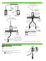
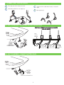
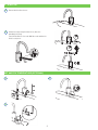
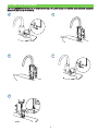
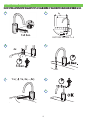
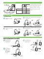
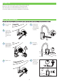
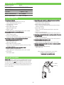
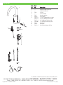
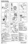
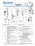
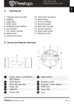
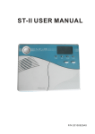
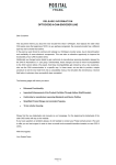
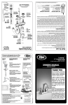
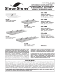
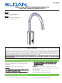
Code No: 0816409
Rev. 1 (07/11)
INSTALLATION INSTRUCTIONS AND USER MANUAL FOR
SLOAN® EAF GOOSENECK SERIES FAUCETS
EAF-700
AC Powered, Sensor Activated Electronic
Gooseneck Hand Washing Faucets
EAF-750
Battery Powered, Sensor Activated Electronic
Gooseneck Hand Washing Faucets
LIMITED WARRANTY
Unless otherwise noted, Sloan Valve Company warrants its product, manufactured and sold for commercial for industrial uses, to be free from defects in material and
workmanship for a period of three (3) years (one (1) year for special finishes, SF faucets, PWT electronics and 30 days for PWT software) from date of first purchase.
During this period, Sloan Valve Compnay will, at its option repair replace, or refund the purchase price of any product which fails to conform with this warranty under
normal use and service. This shall be the sole and exclusive remedy under this warranty. Products must be returned to Sloan Valve Company, at customer’s cost. No
claims will be allowed for labor, transportation or other costs. This warranty extends only to persons or organizations who purchase Sloan Valve Company’s products
directly from Sloan Valve Company for purpose of resale. This warranty does not cover the life of the batteries.
THERE ARE NO WARRANTIES WHICH ExTEND BEYOND THE DESCRIPTION ON THE FACE HEREOF. IN NO EVENT IS SLOAN VALVE COMPANY RESPONSIBLE FOR ANY CONSEqUENTIAL DAMAGES
OF ANY MEASURE WHATSOEVER.
PRIOR TO INSTALLATION
Prior to installing the Sloan Optima EAF-700 Series Faucets,
install the items listed below. Also, refer to rough-in illustrations.
• Lavatory/sink
• Drain Line
• Hot/Cold Water Supply Lines or Tempered Supply
IMPORTANT:
• ALL PLUMBING SHOULD BE INSTALLED IN ACCORDANCE WITH
APPLICABLE CODES AND REGULATIONS.
• FLUSH ALL WATER LINES PRIOR TO MAKING CONNECTIONS.
• KEEP THREAD SEALANT OUT OF YOUR WATERWAY TO PREVENT
COMPONENT PART DAMAGE! DO NOT USE ANY SEALANT ON
COMPRESSION FITTINGS.
Trim Plates
When the EAF Faucet is installed on a sink that has three (3) hole
punchings, a trim plate should be used. Trim Plates must be specified and
ordered separately.
SFP-11 Trim Plate for 4” (102 mm) Centerset Sink
SFP-22 Trim Plate for 8” (203 mm) Centerset Sink
TOOLS REQUIRED FOR INSTALLATION
• 13 mm open end wrench or nut driver for faucet retainer nut
• 5/8” open end wrench for female end of flex hose
FAUCET ROUGH-IN
R
SPOUT
ND
10-1/32”
(147 mm)
MIXING LEVER
(CAN BE SET AND
REMOVED)
3-15/16”
5-11/32”
(100 mm)
(151 mm)
O-RING
2-1/4” (57 mm)
/2” (38 mm)
AX. DECK
HICKNESS
SPOUT
(255 mm)
24°
5-7/8”
0 mm)
HOLE
RED
Model EAF-700/750
1.5 gpm (5.7 Lpm) Max. Flow†
Faucets with Hot/Cold Water Supply
2-9/16”
1-3/16” (30 mm)
MIN. DIA. HOLE
REQUIRED
O-RING
RETAINER
1-1/2” (38 mm)
MAX. DECK
SPOUT
THICKNESS
GASKET
RETAINER
NUT
OLD
PPLY
O-RING
1-1/2” (38 mm)
MAX. DECK
THICKNESS
RETAINER
TEMPERED
SUPPLY
NUT
O-RING
GASKET
RETAINER
MIXING LEVER
If a connection to separate NUT
hot and cold water supplies
is desired, then a Bak-Chek®
13” (330 mm)
13” (330 mm)
tee fitting (not supplied) must
LONG FLEX HOSE be used prior to connecting
LONG FLEX HOSE
HOT
COLD
to the faucet.
SUPPLY † EAF Faucets are furnished withSUPPLY
a 1.5 gpm (3.8 Lpm) spray head).
IMPORTANT: FLUSH DIRT, DEBRIS, AND SEDIMENT FROM SUPPLY LINE(S)
BEFORE CONNECTING FLEx HOSE(S).
B
Remove nut, faucet retainer and gasket.
Install faucet into the center hole in deck or lavatory – 1-3/16”
(30 mm) minimum hole required.
NOTE: If installing the faucet on a three (3) hole sink, a trim plate
should be installed at this time.
1
2
2-1
13” (330 mm)
24°
5-7/8”
LONG FLEX HOSE
HOT
COLD
(147 mm)
1-3/16” (30 mm)
SUPPLY
SUPPLY
MIN. DIA. HOLE
5-11/3
REQUIRED
(151 m
When the EAF faucet is installed on a sink that has three
(3) hole punchings, a trim plate should be used. Trim plate
must be specified and ordered separately:
2-1/4” (57 mm)
ETF-312-A
1-1/2” (38 mm)
Trim Plate for 4” (102 mm) Centerset
Sink
MAX. DECK
ETF-510-A
THICKNESS
Trim Plate for 8” (204 mm) Centerset Sink
1 - INSTALLATION TO DECK
A
1-1/2” (38 mm)
MAX. DECK
THICKNESS
(CAN BE SET AND
REMOVED)
13” (330 mm)
TEMPERED LONG FLEX HOSE
SUPPLY 1-3/16” (30 mm)
MIN. DIA. HOLE
REQUIRED
GASKET
NUT
5
(14
(65 mm)
Model EAF-700/750
1.5 gpm (5.7 Lpm) Max. Flow†
Faucets with
Tempered Water Supply
GASKET
SPOUT
1-3/16” (30 mm)
MIN. DIA. HOLE
REQUIRED
2 - CONNECTION TO WATER SUPPLY
A
Flush supply stops before making connections.
C
B
Tighten the flex hose (with strainer in place) securely to the
supply.
Install strainer and flex hose onto supply stop.
D
Open supply stop(s).
3A - EAF-700 MODELS – PLUG ADAPTER INTO RECEPTACLE
ELECTRICAL CONNECTION FOR UP TO SIx (6) FAUCETS
USING ONE ADAPTER
6 VDC
PLUG-IN
ADAPTER
6”
(152 mm)
CABLE
LENGTH
FROM FAUCET
POWER SPLITTER
ELECTRICAL CABLE
3B - EAF-750 MODELS – CONNECT BATTERY PACK
BATTERY
PACK
Ø 2-13/32”
(61 mm)
LIMIT ONE FAUCET PER BATTERY PACK
3
POWER SPLITTER
ELECTRICAL CABLE
TO ADDITIONAL
FAUCETS
(6 MAx.)
4 - START-UP
A
B
Remove label from faucet sensor.
Activate faucet by pressing the button one (1) time, then
immediately step away.
Faucet will run water for 4 seconds. Wait 10 seconds and then the
faucet is ready to use.
3
3
1x
7
1x
7
1x
7
SET AND FIX TEMPERATURE (OPTIONAL)
A
C
B
4
HOT LIMIT STOP ADJUSTMENT
LIMIT THE MAxIMUM WATER TEMPERATURE. NOTE: THIS DOES NOT TAKE THE PLACE OF AN ASSE 1070 CERTIFIED MIxING DEVICE. BUT IS AN ADDED
MEASURE TO LIMIT DELIVERY OF HOT WATER.
A
D
B
E
C
5
SENSOR RANGE ADJUSTMENT
FACTORY SETTING IS APPROPRIATE FOR THE MAJORITY OF APPLICATIONS AND SHOULD NOT REqUIRE RESETTING UNLESS UNDER ExTREME SITUATIONS.
A
D
2x +
1x5 Sec.
2x
E
4x
5 Sec.
1x(
1x
FACTORY DEFAULT = 6
B
C
8x
7x
1x, 2x,...,5x)
F
G
6
12/24 LINE PURGE FEATURE
1x 24 sec
This feature will operate the faucet every
12 or 24 hours since last use, if not used
to prevent stagnant water conditions.
h
Default purge duration is two minutes.
DEACTIVATE
1x
---
ACTIVATE
2x
12h
3x
24h
Consult factory regarding other timing
options.
I.Q.-CLICK FEATURE
I. CONTINUOUS RUN
A
Continuous run of water for
2 minutes.
B
1 x 2 Sec.
1 x 2 Sec.
1x
1x
Faucet will operate normally after
OR2 minutes or after pressing
i.q.-click button once. OR
1x
1x
OR
OR
1 x 2 Sec.
1 x 2 Sec.
2 min.
2 min.
2 min.
2 min.
II. CLEANING MODE
A
Pause faucet for cleaning for
2 minutes.
B
2x
2x 2x
Faucet will operate normally after 2 minutes or after pressing1
i.q.-click button once.
1x1x
OR
OR
OR
OR
2x
x
1x
min.
2 2min.
min.
22min.
OFF-DELAY (FOLLOW UP1TIME)
x 6 Sec.
1 x 0-5 Sec.
DURATION OF TIME THE WATER RUNS AFTER TARGET
1 x IS REMOVED.
A
Press the button for
1 x 6 Sec.
approximately six (6)
seconds.
1 Release.
x
1 x 6 Sec.
1x
B
C
1 x 0-5 Sec.
1 x 0-5 Sec.
Sensor will flash once
and then the faucet is
ready to operate.
1x
Press again (water
flows) and release
when the desired
time of water flow
(0-5 seconds) is
reached.
7
1x
1x
OPERATION
As the user’s hands enter the beam’s effective range, the beam is reflected
back into the sensor receiver and activates the solenoid valve allowing
water to flow from the faucet. Water will flow until the hands of the user
are removed or until the faucet reaches its automatic time out limit setting.
BATTERY REPLACEMENT
NOTE: REPLACE BATTERY WHEN RED LED INDICATOR FLASHES EACH TIME FAUCET IS IN USE OR WHEN FAUCET STOPS FUNCTIONING.
A
B
E
No need to turn
off water.
Loosen screw
with hex wrench
and remove cap.
Slide cover
forward and lift
off.
Activate faucet
by pressing i.q.
cliq one (1) time,
then immediately
step away.
0V
0V
C
Remove battery.
Replace batteries
with new “CR-P2”
lithium battery.
0V
F
Faucet will
operate for 4
seconds.
G
Wait 10 seconds
and then the
faucet is ready
for operation.
6V
1x
0V
D
6V
Replace cover.
1x
1x
6V
8
6V
1x
6V
TECHNICAL DATA
NOMINAL VOLTAGE
6 VDC
POWER SUPPLY
120 VAC/ 6.75 VDC
WATER PRESSURE
4.3-125 PSI (0.3 - 8.6 bar)
FLOW RATE
1.5 gpm (5.7 Lpm)
WATER FLOW DURATION
0.5-4 seconds
WATER TEMPERATURE
MAx. 176°F/80°C
TROUBLESHOOTING
1. Faucet does not function.
A. Adhesive packaging label affixed over sensor eye.
Remove adhesive label from sensor eye.
B. “Intermittent Off” is activated.
Press button once.
C. Water supply stop(s) closed.
Open water supply stop(s).
D. Battery is “dead”.
Replace battery (refer to Battery Replacement section of guide).
2. Faucet delivers water in an uncontrolled manner.
A. Reflection.
Remove reflective surface.
B. Faucet is not working properly.
Contact Sloan Valve Company Installation Engineering Department.
3. Faucet does not deliver any water when Sensor is activated.
Solenoid Valve produces an audible “CLICK.”
A. Water supply stop(s) closed.
Open water supply stop(s).
B. Water supply stop strainer(s) clogged.
Remove, clean, and reinstall water supply stop strainer(s). Replace
strainer(s), if required.
Solenoid Valve DOES NOT produce an audible “CLICK.”
A. Battery low (battery operated models).
Replace battery (refer to Battery Replacement section of guide).
B. Power failure.
Check power supply.
4. Faucet delivers only a slow flow or dribble when sensor is activated.
A. Water supply stop(s) are partially closed.
Completely open water supply stop(s).
B. Water supply stop strainer(s) clogged.
Remove, clean, and reinstall water supply stop strainer(s). Replace
strainer(s), if required.
C. Spray head is clogged.
Remove, clean, and reinstall spray head. Replace spray head,
if required.
D. Faucet is not working properly.
Contact Sloan Valve Company Installation Engineering Department.
5. Faucet does not stop delivering water or contrinues to drip after user is
no longer detected.
A. Faucet is not working properly.
Contact Sloan Valve Company Installation Engineering Department.
6. LED indicator blinks when faucet is in use.
A. Battery low (battery operated models).
Replace battery (refer to Battery Replacement section of guide).
7. The water temperature is too hot or too cold on a faucet connected to
hot and cold supply lines.
A. Supply stops are not adjusted properly.
Adjust supply stops.
When assistance is required, please contact Sloan’s
Installation Engineering Department at:
1-888-SLOAN-14 (1-888-756-2614)
CARE AND CLEANING
DO NOT USE abrasive or chemical cleaners (including chlorine bleach) to
clean faucets that may dull the luster and attack the chrome or special
decorative finishes. Use ONLY mild soap and water, then wipe dry with
clean cloth or towel. While cleaning the bathroom sink, protect the faucet
from any splattering of cleaner. Acids and cleaning fluids will discolor or
remove chrome plating.
9
PARTS LIST
1
2
3
5
Item
No.
Part
No.
Description
1
2
3
4
5
6
7
8
––
––
––
EAF-2
––
EAF-1
EAF-44
EAF-24-A
EAF-25-A
EAF-17-A
EAF-1008
EAF-9
EAF-48
EAF-11-A
Spout Assembly
Integral Side Mixer Handle Cap
Integral Side Mixer Kit
Solenoid
Sensor Assembly
Mounting Hardware
Power Splitter
11-13/16” (300 mm) Extension Cable
47-1/4” (1200 mm) Extension Cable
126” (3200 mm) Extension Cable
13” (330 mm) Flexible Supply Hose
Filter/Strainer
Battery Box
Plug-in Voltage Adapter, US Plug
9
10
11
12
4
6
8
7
9
10
11
12
The information contained in this document is subject to change without notice.
SLOAN VALVE COMPANY • 10500 SEYMOUR AVENUE • FRANKLIN PARK, IL 60133
Phone: 1-800-9-VALVE-9 (1-800-982-5839) • Fax: 1-800-447-8329 • www.sloanvalve.com
Copyright © 2011 SLOAN VALVE COMPANY
Code No.: 0816409 – Rev. 1 (07/11)