1
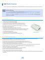
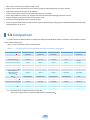
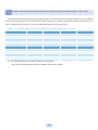
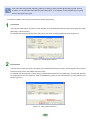
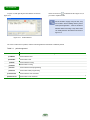
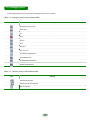
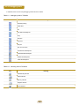
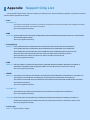
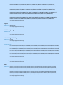
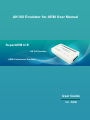
AK100 Emulator for ARM User Manual SuperARM ICE AK100 Emulator ARM Professional Emulator User Guide for ARM Manufacturer and Technical Support Guangzhou Zhiyuan Electronics Co.,Ltd Address: 2 floor 3 building,Huangzhou industrial zone,Chebei road,Tianhe district,Guangzhou city Code Postal: 510660 TEL: (020) 22644372 28872453 (sale) (020) 22644360 28267808 E-mail: [email protected] (technical support) (technical support) FAX: (020) 38601859 Web: www.embedtools.com Sales and Service Networks Guangzhou ZLG MCU Technology Co.,Ltd Address: F4 room 12 floor Guangda Bank building,Tianhe north road No.689,Tianhe district,Guangzhou city Code Postal: 510630 TEL: (020) 38730916 38730917 38730976 38730977 Web: www.zlgmcu.com FAX: (020) 38730925 Guangzhou ZLG Shenzhen ZLG Address:203 room Saige building,Tianhe district Address:D room 4 floor,Shennan road No.2070,Shenzhen city TEL: (020) 87578634 TEL: (0755) 83781768 83781788 83782922 87569917 87578842 FAX: (020) 87578842 FAX: (0755) 83793285 Chengdu ZLG Chongqing ZLG Address: 401 room,One loop road south two section,Chengdu Address:1611 room Saige building,Shiqiao road,Chongqing city TEL: (028) 85439836 TEL: (023) 68796438 85432683 85437446 68796439 FAX: (028) 85437896 FAX: (023) 68796439 Wuhan ZLG Beijing ZLG Address:12128 room,Geyu road No.158,Huangshan district Address:1207 room,Zhichun road No.113,Haidian district TEL: (027) 87168497 TEL: (010) 62536178 87168297 87168397 62536179 82628073 FAX: (027) 87163755 FAX: (010) 82614433 Shanghai ZLG Hangzhou ZLG Address:7E room,Beijing east road No.668,Shanghai city Address:502 room,Tianmushan road No.217,Hangzhou city TEL: (021) 53083452 TEL: (0571) 28139611 53083453 53083496 28139612 28139613 FAX: (021) 53083491 FAX: (0571) 28139621 Nanjing ZLG Xian ZLG Address:2006 room,Zhujiang road No.280,Nanjing city Address:1201 room,Changan north road No.54,Xian city TEL: (025) 83613221 TEL: (029) 87881296 FAX: (025) 83613271 83603005 83603500 FAX: (029) 87880865 83063000 87881295 Table of Contents Chapter 1 Chapter 5 AK100 Introduction Emulation ARM In IAR 1.1 Introduction 5 5.1 Add driver file 31 1.2 Performance 6 5.2 Debugging 33 1.3 Comparison 7 5.2.1 Start debugging 33 5.2.2 Debugging tools 34 5.2.3 Debugging results 35 Chapter 2 Use AK100 Emulator 2.1 Install driver 10 2.2 Hardware connection 11 Chapter 3 Emulation ARM In Keil 3.1 IDE settings 14 3.2 Emulator settings 15 3.2.1 Device&hardware 15 3.2.2 Main options 16 3.3 Chapter 6 Emulation ARM In TKStudio 6.1 IDE settings 37 6.2 Debugging 38 6.2.1 Start debugging 38 6.2.2 Debugging tools 39 6.2.3 Debugging results 40 Chapter 7 Technical Support 3.2.3 TAP config 17 3.2.4 Flash program 18 7.1 Update method 42 3.2.5 21 7.2 Contact us 42 3.2.6 TKScope doctor 23 7.3 Thanks 43 Debugging 23 3.3.1 Start debugging 23 3.3.2 Debugging tools 24 3.3.3 Debugging results 25 Init file Chapter 4 Emulation ARM In ADS 4.1 Add driver file 27 4.2 Debugging 28 4.2.1 Debugging tools 28 4.2.2 Debugging results 29 Appendix Support Chip List Chapter 1 AK100 Introduction 1.1 Introduction 5 1.2 Performance 6 1.3 Comparison 7 1.1 Introduction AK100 is a high-performance ARM emulator, which designed by Guangzhou Zhiyuan Electronics Co.,Ltd. in 2009.It supports a full range of ARM7 / ARM9 / Cortex-M0 / Cortex-M1 / Cortex-M3 / XSCALE etc.AK100 communicates with PC by USB2.0 (High Speed) interface,the speed is very fast. This text introduces the performance and using method of AK100 that emulates ARM core. At present,categories of ARM core that AK100 supported are as follows: ARM7:ARM7TDMI / ARM7TDMI-S / ARM7EJ-S / ARM720T; ARM9:ARM9TDMI / ARM920T / ARM922T / ARM926EJ-S / ARM946E-S / ARM966E-S; Cortex:Cortex-M0 / Cortex-M1 / Cortex-M3; XSCALE:PXA255 / PXA270. AK100 supports all the mainstream IDE,such as TKStudio / Keil / ADS / IAR / RealView / Eclipse / SDT and so on,to ensure consistency of your development platform. At present,IDE environments that AK100 supported are as follows: TKStudio:Zhiyuan company,chinese/english language,multi-core compling/debugging,powerful editor; Keil:Keil company, english language,8051/251/C166/ARM core compling/debugging; ADS: ARM company, english language,full cores of ARM compling/debugging; IAR:IAR company, english language, multi-core compling/debugging; RealView:ARM company, english language,full cores of ARM compling/debugging. TKStudio 4.5 IAR V6/V5/V4 Keil µV4/µV3/µV2 Eclipse 5 ARM ADS 1.2 RVDS 4.0/2.2 1.2 Performance AK100 is a high-performance ARM emulator,it is dedicated to ARM core emulation.Its performance is the same to the TKScope’s. TKScope introduction! TKScope embedded intelligent emulator supports a full range of ARM / DSP / AVR / 8051 / C166 / C251 / C8051F / MX Core etc, supports all the mainstream IDE,such as TKStudio / Keil / ADS / IAR / CCS / RealView / AVRStudio / SDT and so on;meantime, 64-way professional logic analyzer is built-in it, zlgLogic advanced software is fully supported. AK100 emulator hardware index USB2.0 high-speed communication interface. The fastest speed of programming is 600KB/S. Standard windows USB driver supported,used immediately while linking. Standard 20-pin JTAG interface connects to the board,supports hot-swap. PC supplies it with power by USB interface,so power adapter is not necessary. Show working state by display led. Detect all the JTAG signals and the voltage of target board. Adapt voltage to target board automatically,support a wide range of voltage 1.8V~5V. The maximum clock of JTAG is 25MHz,can reach the limit speed of debugging. Can identify speed automatically. Support RTCK clock,adapt clock automatically. Facilitate the detection of hardware failure with TKScope doctor. AK100 emulator AK100 emulator function and feature Support a full range of ARM core,such as ARM7/ARM9/ARM11/Cortex-M0/Cortex-M1/Cortex-M3/XSCALE and so on. Support SWD mode of debugging Cortex-M0/Cortex-M1/Cortex-M3 core. Support all the mainstream IDE,such as TKStudio/Keil/ADS/IAR/RealView/SDT and so on. Support programming/debugging in-chip Flash in-circuit,provide Flash algorithm file of each chip. Provide a graphic interface for programming Flash configuration. Support programming/debugging out-chip Flash in-circuit,provide thousands of Flash algorithm file that are used commonly. Support multiple types of external Flash to programming/debugging,such as NOR/NAND/SPI and so on. Allow users to add their own Flash algorithm file. Provide a separate software for programming Flash to increase productivity. Support setting unlimited breakpoints in RAM while debugging. Support setting unlimited breakpoints in Flash while debugging. The speed of debugging in Flash is as fast as that in RAM,because of synchronous Flash technology,that can quickly refresh Flash breakpoints. 6 Allow users to set/cancel any breakpoint while running. Support users to follow the running tracks of complex program by setting breakpoints of program and data. Rapid single-step,the fastest speed is 180 steps/sec. Ensure to debug target system fast and stable,which frequency is changing. Able to debug ARM core which is in an irregular state because of that special debugging algorithm is built-in. Support debugging multi-devices which connect by daisy-chain. Provide the perfect initialization files to hundreds of chips. Able to set system flexibly before and after reset/running/Flash programming,including register setting/ARM initialization/clock setting /delay/information cue an so on. 1.3 Comparison At present,the famous ARM emulators are Ulink2/J-link.While,TKScope/AK100/AK100Pro are better,they will beat all the emulators by their perfect performances. Table 1.1 is the comparision of famous ARM emulators. Table 1.1 AK100/AK100Pro/TKScope K9/Ulink2/J-link performance comparison Emulator AK100Pro AK100 TKScope K9 Ulink2 J-link supported IDE* TKStudio,Keil,ADS,IA R,RealView TKStudio,Keil,ADS,IA R,RealView TKStudio,Keil,ADS,IA R,RealView Keil Keil,ADS,IAR RAM breakpoint unlimited unlimited unlimited unlimited unlimited Flash breakpoint* unlimited unlimited unlimited 2max not support external Flash set breakpoint while running support support support support support RTCK support support support support support program in-chip Flash support support support support support program out-chip Flash* support support support support support support support support not support not support NOR/NAND/SPI NOR/NAND/SPI NOR/NAND/SPI NOR/NAND/SPI NOR users add Flash algorithm* support support support support not support speed of programming RAM* 1.2MB/S 600 KB/S 650 KB/S 28KB/S 600 KB/S JTAG clock* <=25MHz <=25MHz <=25MHz <=10MHz <=12MHz step(step/sec)* ≈180 ≈150 ≈150 ≈50 ≈100 company zhiyuan zhiyuan zhiyuan Keil Segger graphic interface of programming Flash configuration* supported types of external Flash* ps:①The performances of Ulink2/J-link are from their web. ②The prominent performances of AK100/AK100Pro/TKScope K9 mark with*. 7 The speed of AK100/AK100Pro/TKScope K9/Ulink2/J-link programming Flash is really tested.Table 1.2 is the results. AK100/AK100Pro/TKScope K9/Ulink2/J-link test the chip NXP LPC2138 ,all the states are the same,the size of code is 512KB,the clock of working is 77MHz.The code is programmed into Flash or RAM in turn by all the emulators,then record the time,accuracy is 0.1 sec.Any condition,the clock is RTCK or fixed JTAG 1MHz/2MHz/3MHz in turn,record four times. Table 1.2 AK100/AK100Pro/TKScope K9/Ulink2/J-link programming speed(LPC2138) 512KB Flash JTAG 1MHz JTAG 2MHz JTAG 3MHz RTCK AK100Pro (sec) 14 8 7 6 TKScope K9 (sec) 15 9 7.5 6.5 AK100 (sec) 15 9 7.5 6.5 Ulink2 (sec) 28 28 28 28 J-link (sec) 26 20 fail 27 512KB RAM JTAG 1MHz JTAG 2MHz JTAG 3MHz RTCK AK100Pro (sec) 6.5 3.0 2.8 2.5 TKScope K9 (sec) 6.5 3.5 3 3 AK100 (sec) 8 4.5 3.5 3 Ulink2 (sec) 23 23 23 23 J-link (sec) 7 4 fail 6 ps:①The states of testing are the same,the results are recorded really. ②The code size of programming LPC2138 is 512KB,the system clock is 77MHz. 8 Chapter 2 Use AK100 Emulator 2.1 Install driver 10 2.2 Hardware connection 11 2.1 Install driver Users must install driver before using AK100 emulator,otherwise,it can not work!The driver programme of AK100 is the same to the TKScope’s. Driver must be installed into the Keil RealView MDK directory,if you use it;else arbitrary directory. 1 Double click TKScopeSetup_ARM_en.EXE,the system For example,Keil RealView MDK is installed on C disk, 2 will pop-up dialog box as shown in figure 2.1,then click [Next] to continue. Figure 2.1 install driver 4 after driver installed. Double-click vcredist_x86_en.exe, the system will pop-up dialog box as shown in figure 2.3,then click [Yes] to continue. Figure 2.3 shown in figure 2.2. Figure 2.2 It is recommended that users install vc8 from Microsoft 3 then,driver must be installed in directory C:\Keil,as driver installation path Until now,all the necessary drivers of AK100 are installed.In the installation directory (example is C:\Keil\ \TKScope), you can see driver files for various environments, as shown in figure 2.4. install vc8 Figure 2.4 10 driver files The types of various driver files and their application development environment can be read in the readme file that under the installation directory (example figure 2.4). Table 2.1 lists all the driver files for ARM at present. Table 2.1 driver files list driver file driver type application environment ULP2ARM_TKSCP_DRV_ARM_for_AGDI.dll ARM Keil Uvsion4/Uvsion3/Uvsion2 TKSCP_DRV_ARM_for_IAR_v4.dll ARM IAR V4 TKSCP_DRV_ARM_for_IAR_v5.dll ARM IAR V5 TKSCP_DRV_ARM_for_IAR_v5.dll ARM IAR V6 TKSCP_DRV_for_RDI.dll ARM AXD(ADS),and other RDI agreement 2.2 Hardware connection Users need to connect AK100 emulator with PC and target board before using it. Connect emulator with PC AK100 emulator connects with PC by USB,can be used immediately while linking. After USB linked,the Power led of AK100 is lighting up,Busy led will go out after lighting up one time. Busy led will blink incessantly while communicating. Connect emulator with target board AK100 emulator connects with JTAG of target board by 20Pin cable,supports hot-swap. The system will require users to install driver of new USB equipment while using the first time. 11 Install driver of USB equipment 1 AK100 emulator is used for the first time,the system 2 will pop-up dialog box as shown in figure 2.5. Now,you need to specify location of USB driver. Figure 2.5 option in figure 2.5,then click [Next],the system will pop-up dialog box as shown in figure 2.6. new hardware installation wizard Figure 2.6 In figure 2.6,click [Browse] option,open the dialog box as 3 Select [Install from a list or specific location(Advanced)] shown in figure 2.7,then find the driver files in AK100 installation directory(example is C:\Keil\TKScope\Driver\ 4 select driver box After drive installation finished,the system will pop-up dialog box as shown in figure 2.8,Now,click [Finish] to complete. AK100 Driver\WinXP),then click [OK]. Figure 2.7 designated driver Figure 2.8 12 new hardware installation completed Chapter 3 Emulation ARM In Keil 3.1 IDE settings 14 3.2 Emulator settings 15 3.2.1 Device&hardware 15 3.2.2 Main options 16 3.2.3 TAP config 17 3.2.4 Flash program 18 3.2.5 Init file 21 3.2.6 TKScope doctor 23 3.3 Debugging 23 3.3.1 Start debugging 23 3.3.2 Debugging tools 24 3.3.3 Debugging results 25 3.1 IDE settings 1 2 In Keil RealView MDK,open the project that is compiled ok,as shown in figure 3.1. Click icon in figure 3.1,open the interface of project settings as shown in figure 3.2. Figure 3.2 project settings interface Figure 3.1 MDK interface 3 In figure 3.2,select the hardware emulation,the corresponding driver select [TKScope Debug for ARM].Then,click [Settings] into the interface of AK100 settings,as shown in figure 3.3. Message box Figure 3.3 AK100 settings interface In figure 3.3,click the left side of the various options,the system will pop-up the appropriate settings interface, while the right side of the information prompt box will appear the specific meaning of the various settings. 14 3.2 Emulator settings Users must correctly set the configurations of AK100,otherwise,AK100 will not work normally. 3.2.1 Device&hardware In figure 3.3,click [Device & hardwire] into the interface as shown in figure 3.4. Figure 3.4 device&hardwire interface Users must select chip and emulator correctly in [Device & hardwire] as shown in figure 3.4. 1 2 Users can select chip and emulator directly. Users can input chip in [Device Info & Mask],then system will quickly find the chip automatically. Users can find emulator by [Search].The method is that users only select chip,then click [OK] to return the interface as shown in figure 3.3;now,click [Search], system will check out the emulator automatically as shown in figure 3.5. Figure 3.5 search results 15 3.2.2 Main options 1 In figure 3.3,click [Main options] into the interface as shown in figure 3.6. Cache [cache code]:don't read code from hardware if it be readed. [cache data]:don't read data from hardware if it be readed, except meet a run. 2 Step [use software step]:don't repeat programming Flash Breakpoints. 3 Break [use software break point]:to achieve unlimited breakpoints to debug in RAM. [use flash break point]:to achieve unlimited breakpoints to debug in flash. 4 Figure 3.6 main options interface Endianness Choose endian for the device, big endian or little endian. If the endian of the device is fixed,no endian choice 6 here. Clock mode 5 [Auto speed]:auto select the best JTAG speed. [Adaptive speed]:select max speed based on RTCK Clock if the device has. [Sys clock]:your system clock frequence(MHz). [Fixed speed]:select the speed you want. [JTAG clock]: your JTAG clock frequence(MHz). 16 7 Hardware resset options [Use SRST]:Use SRST. [Use TRST]:Use TRST. [Reset hold]:Reset hold delay time(ms). [Reset restore]:Reset release delay time(ms). Reset hold time Reset release time Start debugging RST Figure 3.7 reset signal Reset release time depond on the reset chip of target board.The time is must longer than the time of reset chip; otherwise,the emulator worked already while the target don’t finish reset,then the emulator will not work! 8 Core reset and halt [Core reset]:no reset,soft reset. [Core halt]:auto,use DBRQ,use break point,use special method. 3.2.3 TAP config In figure 3.3,click [TAP config] into the interface as shown infigure 3.8. [TAP config] is applied to setup the JTAG chian,include numbers of devices,IR length,active device. It's important to setup when there is unkown device in the JTAG chian. Normally, [Automatic Detection] option will be ok. Figure 3.8 TAP config interface 17 [devices list]:list all devices in scan chain,include name,IR length,idcode. [IDCODE]:the idcode of the device,for add,update operations. [name]:the name of the device. [IR length]:the IR length of the JTAG device. [Automatic Detection]:setup scan chian automatically. [Manual Configuration]:setup manually. [Add]:add a new device in the devices list. [Delect]:delect a device in the devices list. [Update]:update the device in the devices list. [Up]:move the selected device upward. [Down]:move the selected device downward. 3.2.4 Flash program In figure 3.3,click [Flash program] into the interface as shown 1 in figure 3.9. Program options [Erase Chip]:erase all Flash onchip before download. [Erase Sectors]:erase the sector that download used. [not Erase]:don't erase the flash. 2 RAM for Algorithm [start]:start address of ram for run flash program algorithm. [size]:the ram size. Figure 3.9 flash program interface 3 Programming Algorithm [start]:Flash Algorithm start re_address. [size]:Flash Algorithm start re_size. Flash programming algorithms can be loaded up to foru,but the address can not overlap. The algorithm can be written by yourself, and loaded here. 4 Flash access [Add]:add a new programming algorithm. [Remove]:remove a programming algorithm selected. 18 Users must select the [program] and [verify] options,if you debug in Flash,and select [Erase Chip] or [Erase Sectors]. In addition, it is recommended users select the [skip match] option, so the repetition of Flash programming can greatly enhance the programming speed. The follows will explain a few commonly used methods of Flash programming. 1 In chip Flash If the chip has Flash,system will load the Flash algorithm file automatically.Now,select [Program] and [Verify],while select [Erace Chip] or [Erace Sectors]. For example, NXP LPC2132 has 64K Flash, debug this chip in Flash, the setting interface as shown in figure 3.10. Figure 3.10 2 flash program interface 1 External Flash If the chip has no Flash,users need to download code to external Flash.Now,users need to add the algorithm file of external Flash,and properly set the start address and size of Flash. For example, NXP LPC2220 has no Flash, debug in external Flash SST39VF160.Click [Add] option, load the Flash algorithm file of SST39VF160.The start address is setted to 0x80000000 according to chip characteristics.The setting interface is as shown in figure 3.11. Figure 3.11 flash program interface 2 19 AK100 emulator supply many Flash algorithm files,they are located in driver installing directory that is TKScope\configuration\… Files are located in different folders according to Flash firms. 3 In chip Flash and external Flash If the chip has Flash,and the board has external Flash,users need to download code to chip Flash snd external Flash in order. The system will load the chip Flash algorithm file automatically, users need to add the algorithm file of external Flash.The method of adding Flash algorithm file is the same.Users can add several Flash algorithm files. Now,users need to set the start address and size of any Flash,the address of Flash can not overlap. For example, NXP LPC2292 has 256K Flash,external Flash are two SST36VF1601,users debug in chip Flash and external Flash.The system will load the Flash algorithm file of LPC2292 automatically,users need to add the Flash algorithm files of SST36VF1601.Then, the start address are setted to 0x80000000 and 0x81000000 according to LPC2292 characteristics.The address of two SST36VF1601 is not overlap, the setting interface is as shown in figure 3.12. Figure 3.12 4 flash program interface 3 RAM debug Users don't need to select [program] option while debugging in RAM, the setting interface is as shown in figure 3.13. Figure 3.13 flash program interface 4 20 3.2.5 Init file In figure 3.3,click [Init file] into the interface as shown in Users can click coin figure 3.14. to add the init file in figure 3.14,if you want to replace the file. AK100 emulator supply many init files, they are located in driver installing directory that is TKScope\configuration\… Files are located in different folders according to chip firms.Users can modify the file in the interface as shown in figure 3.14. Figure 3.14 init file interface Init macro is a file with .ini postfix,is used for executing different commands in different periods. Table 3.1 period supported name meaning preRESET execute before reset postRESET execute after reset preRUN execute before running postRUN execute after running preFlash execute before Flash programming postFlash execute after Flash programming preDownload execute before code download postDownload execute after code download 21 Table 3.2 action supported name meaning Read 32bit read 32bit data in specified address Read 16bit read 16bit data in specified address Read 8bit read 8bit data in specified address Write 32bit write 32bit data in specified address Write 16bit write 16bit data in specified address Write 8bit write 8bit data in specified address SetJtagClock set JTAG mode and frequence (decimal) Delay delay,unit ms (decimal) SetPC set program conter (hex) Message output messages It is supported unlimited times actions in every period,start number is 0. Users can write their own init files according to their own applications.The follows is an example. [postRESET] InitStep0_Action = "Write 32bit" InitStep4_Action = "Message" InitStep0_Comment = "MEMMAP internal flash" InitStep4_Value0 = "Hi!This is a message!" InitStep0_Value0 = 0xE01FC040 InitStep0_Value1 = 0x1 InitStep5_Action = "SetPC" InitStep5_Comment = "Set PC" InitStep1_Action = "SetJtagClock" InitStep1_Comment = "1MHz fixed JTAG " InitStep1_Value0 = "FixedJtagClock" [preRun] InitStep1_Value1 = 10000000 InitStep0_Action = "SetJtagClock" InitStep0_Comment = "Set auto clock" InitStep2_Action = "Read 32bit" InitStep0_Value0 = "AutoJtagClock" InitStep2_Comment = "Read 32bit data" InitStep2_Value0 = 0xE01FC080 InitStep2_Value1 = 0 [postRun] InitStep0_Action = "SetJtagClock" InitStep3_Action = "Delay" InitStep0_Comment = "Set RTCK" InitStep3_Comment = "delay 1000ms" InitStep0_Value0 = "SycJtagClock" InitStep3_Value0 = 1000 22 3.2.6 TKScope doctor In figure 3.3,click [TKScope doctor] into the interface as The results of TKScope doctor must be all right,otherwise, shown in figure 3.15. AK100 emulator will not work normally. The function of TKScope doctor is very powerful,detecting own hardware init, USB communication,hardware reset, and reading ARM core ID 100000 times. Figure 3.15 TKScope doctor 3.3 Debugging AK100 emulator is setted right,users can use it debugging. 3.3.1 Start debugging Users can click [Start/Stop Debug Session] option in [Debug] menu or click coin figure 3.16. Figure 3.16 debugging interface 23 to into the state of debugging,as shown in 3.3.2 Debugging tools In Keil RealView MDK,users can use many debugging tools as shown in follows. Table 3.3 debugging tools in Keil RealView MDK icon meaning Start/Stop Debug Session Reset CPU Go Stop Step In Step Step Out Run To Cursor Insert/Remove Breakpoint Kill All Breakpoints Enable/Disable Breakpoint Disable All Breakpoints Table 3.4 watching tools in Keil RealView MDK icon meaning Disassembly Window Watch and Call Stack Window Memory Window 24 3.3.3 Debugging results After debugging over,users can click [Start/Stop Debug Session] option in [Debug] menu or click coin to exit the state of debugging. If users debug in RAM,the programs written in the chip RAM will lost after power down.Programs will not run in target board if power up again. If users debug in Flash,the programs written in the Flash will save after power down.Programs will run in target board if power up again. If users debug in Flash and encryption,programs will run in target board if power up again,but users can not debug. Unless,users erase global chip by ISP spftware,then can debug again. 25 Chapter 4 Emulation ARM In ADS 4.1 Add driver file 27 4.2 Debugging 28 4.2.1 Debugging tools 28 4.2.2 Debugging results 29 4.1 Add driver file In ADS,open the project that is compiled ok, as shown 1 in figure 4.1.Users can click icon to into the AXD, as shown in figure 4.2. Figure 4.3 Choose Target window The system will pop-up dialog box as shown in figure 4 Figure 4.1 2 ADS interface 4.4,users open the installation directory of AK100 driver(example is C:\Keil\TKScope),then select TKSCP_DRV_for_RDI.dll as shown in figure 4.4. In AXD,users select the [Configure Target] option in [Options] menu,as shown in figure 4.2. Figure 4.4 select driver file 5 The [Choose Target] window will display the currently installed driver options, as shown in figure 4.5. Users select AK100 driver,then click [Configure] to into the interface of AK100 settings, as shown in figure 4.6. Figure 4.2 AXD interface 3 The system will pop-up [Choose Target] window as shown in figure 4.3.Click [Add] to add the driver file of AK100. Figure 4.5 27 driver file installed 6 The interface of AK100 settings is the same in any IDE environment (for example,figure 4.6 in ADS and figure 3.3 in Keil RealView MDK),the method of settings is also the same. Figure 4.6 AK100 settings interface Users must correctly set the configurations of AK100,otherwise,AK100 will not work normally. The method of settings is not described repeatedly in here,users please refer to the 3.2 section<Emulator settings>. 4.2 Debugging In AXD,driver is installed OK and AK100 emulator is setted right,users can use it debugging. 4.2.1 Debugging tools Table 4.1 debugging tools in AXD icon meaning Go Stop Step In Step Step Out Run To Cursor Toggle BreakPoint 28 Table 4.2 watching tools in AXD Icon meaning Processor Registers Processor Watch Context Variable Memory Disassembly Table 4.3 file operation tools in AXD Icon meaning Load Image Reload Current Image 4.2.2 Debugging results After debugging over,users can close AXD interface to exit the state of debugging. If users debug in RAM,the programs written in the chip RAM will lost after power down.Programs will not run in target board if power up again. If users debug in Flash,the programs written in the Flash will save after power down.Programs will run in target board if power up again. If users debug in Flash and encryption,programs will run in target board if power up again,but users can not debug.Unless, users erase global chip by ISP spftware,then can debug again. 29 Chapter 5 Emulation ARM In IAR 5.1 Add driver file 31 5.2 Debugging 33 5.2.1 Start debugging 33 5.2.2 Debugging tools 34 5.2.3 Debugging results 35 5.1 Add driver file In IAR,open the project that is compiled ok.Select the 1 3 project,click the right botton of mouse,then select the [Options],as shown in figure 5.1. Figure 5.1 IAR interface 2 settings is as shown in figure 5.3,all the options don’t need to select. Figure 5.3 Select [Debugger] option,[Setup] window in right side 4 is setted as shown in figure 5.2. [Driver] option is selected [Third-Party Driver] and [Run to main]. Figure 5.2 In figure 5.2,click [Download] option,the interface of Debugger Setup interface Debugger Download interface Select [Third-Party Driver] option,the interface is as shown in figure 5.4. Click icon to add the driver file of AK100. Figure 5.4 Third-Party Driver interface 31 5 The system will pop-up dialog box as shown in figure 7 5.5,users open the installation directory of AK100 driver(example is C:\Keil\TKScope). IAR main menu will display [TKScope] option after driver file installed,as shown in figure 5.7. If you use IAR V4,select the driver file is TKSCP_DRV_ARM_for_IAR_v4.dll; If you use IAR V5,select the driver file is TKSCP_DRV_ARM_for_IAR_v5.dll; If you use IAR V6,select the driver file is TKSCP_DRV_ARM_for_IAR_v6.dll. Figure 5.7 main interface 8 Figure 5.5 6 Users can select [Setup] option in [TKScope] menu to into the interface of AK100 settings,as shown in figure 5.8. select driver file Driver file installed,the [Third-Party Driver] window will display the currently installed driver option,as shown in figure 5.6. Figure 5.8 Figure 5.6 driver file installed 32 select AK100 settings 9 The interface of AK100 settings is the same in any IDE environment (for example,figure 5.9 in IAR and figure 3.3 in Keil RealView MDK),the method of settings is also the same. Figure 5.9 AK100 settings interface Users must correctly set the configurations of AK100,otherwise,AK100 will not work normally. The method of settings is not described repeatedly in here,users please refer to the 3.2 section<Emulator settings>. 5.2 Debugging AK100 emulator is setted right,users can use it debugging. 5.2.1 Start debugging Users can click [Debug] in [Project] menu or click coin to into the state of debugging,as shown in figure 5.10. Figure 5.10 start debugging 33 5.2.2 Debugging tools In IAR,users can use many debugging tools as shown in follows. Table 5.1 debugging tools in IAR icon meaning Make and Debug Toggle Breakpoint Reset Break Step Over Step Into Step Out Next Statement Run to Cursor Go Stop Debugging Users can open windows under [View] menu to watch results in debugging,as shown in figure 5.11. Figure 5.11 open view windows 34 5.2.3 Debugging results After debugging over,users can click coin to exit the state of debugging. If users debug in RAM,the programs written in the chip RAM will lost after power down.Programs will not run in target board if power up again. If users debug in Flash,the programs written in the Flash will save after power down.Programs will run in target board if power up again. If users debug in Flash and encryption,programs will run in target board if power up again,but users can not debug. Unless,users erase global chip by ISP spftware,then can debug again. 35 Chapter 6 Emulation ARM In TKStudio 6.1 IDE settings 37 6.2 Debugging 38 6.2.1 Start debugging 38 6.2.2 Debugging tools 39 6.2.3 Debugging results 40 6.1 IDE settings In TKStudio,open the project that is compiled ok, as 1 shown in figure 6.1.Users can click icon to into the interface of project settings,as shown in figure 6.2. Figure 6.3 4 Hardware Emulation interface The system will pop-up dialog box as shown in figure 6.4,users need to select the type of driver interface. Example,users select RDI,then click [OK]. Figure 6.1 TKStudio interface 2 Open [ARM Debug] option in [Debuger],then select [Hardware Emulation] in the right side window,as shown in figure 6.2. Figure 6.4 driver interface type Users open the installation directory of AK100 driver 5 Figure 6.2 3 (example is C:\Keil\TKScope),then select TKSCP_DRV _for_RDI.dll as shown in figure 6.5. project settings Open [Hardware Emulation] interface,as shown in figure 6.3.Click [Add] to add the driver file of AK100. Figure 6.5 37 select driver file Driver file installed,the [Hardware Emulation] window 6 The interface of AK100 settings is the same in any IDE 7 will display the currently installed driver option,as shown in figure 6.6.Users select AK100 driver,then click [Config] to into the interface of AK100 settings, environment (for example,figure 6.7 in TKStudio and figure 3.3 in Keil RealView MDK),the method of settings is also the same. as shown in figure 6.7. Figure 6.7 AK100 settings interface Figure 6.6 driver file installed Users must correctly set the configurations of AK100,otherwise,AK100 will not work normally. The method of settings is not described repeatedly in here,users please refer to the 3.2 section<Emulator settings>. 6.2 Debugging AK100 emulator is setted right,users can use it debugging. 6.2.1 Start debugging Users can click [Start/Stop Debug] option in [Debug] menu or click coin Figure 6.8 to into the state of debugging,as shown in figure 6.8. debugging interface 38 6.2.2 Debugging tools In TKStudio,users can use many debugging tools as shown in follows. Table 6.1 debugging tools in TKStudio Icon meaning Start/Stop Debug Reset CPU Go Run Without Breakpoint Stop Step into Step over Step out Run To Cursor line Insert/Remove Breakpoint Enable/Disable Breakpoint Disable All Breakpoints Clear All Breakpoints Table 6.2 watching tools in TKStudio Icon meaning Disassembly Window Watch Window Memory Window Register Window SFRS Window 39 6.2.3 Debugging results After debugging over,users can click [Start/Stop Debug Session] option in [Debug] menu or click coin to exit the state of debugging. If users debug in RAM,the programs written in the chip RAM will lost after power down.Programs will not run in target board if power up again. If users debug in Flash,the programs written in the Flash will save after power down.Programs will run in target board if power up again. If users debug in Flash and encryption,programs will run in target board if power up again,but users can not debug. Unless,users erase global chip by ISP spftware,then can debug again. 40 Chapter 7 Technical Support 7.1 Update method 42 7.2 Contact us 42 7.3 Thanks 43 7.1 Update method AK100 emulator will upgrade incessantly,will support the new chips of each companys.The method of AK100 upgrading is updating software.Users download and install the new driver,then can debug the new chips. The driver of AK100 emulator announces in ZLG web http://www.zlgmcu.com,users can download the new driver freely at any moment. 7.2 Contact us Thanks for using AK100 emulator,we will provide the best technical support with you and help you to solve the problems in development for using emulator.We suggest that you contact with us by following methods,so we can solve problems quickly and save your times. 1 2 3 TEL/FAX BBS It is the best method that we communicate by phone, Welcome to BBS of ZLG and we can solve problems quickly.Before you call up, http://www.zlgmcu.com.cn/index.asp,we open the please collate your problems and put the emulator special BBS for emulator.You can write out your next to computer and phone. problems,our engineers will give you answers,and other TEL:020-22644360,28267808, net friends will also give you answers. 4 Email Maintenance You can give us email to describe your problems in If your emulator break down in using,please deliver it to detail and offer demo programs,so we can help you us.We will provide the perfessional maintenance. analyze problems in the round. Company: Guangzhou Zhiyuan Electronics Co.,Ltd. Email: [email protected] . Address:4 floor 3 building,Huangzhou industrial zone, Chebei road,Tianhe district,Guangzhou city. TEL:020-22644245. Users must correctly set the configurations of emulator,otherwise,emulator will not work normally.So the problems of emulator are usually due to the wrong configurations of emulator. If you consider the emulator is breaken down,we suggest that you contact with us before delivery.Our engineers will confirm the emulator is breaken down whether or not. 42 7.3 Thanks AK100 is a high-performance ARM emulator, which designed by Guangzhou Zhiyuan Electronics Co.,Ltd. in 2009.It supports a full range of ARM7 / ARM9 / Cortex-M0 / Cortex-M1 / Cortex-M3 / XSCALE etc.AK100 communicates with PC by USB2.0 (High Speed) interface,the speed is very fast. AK100 can beat all the emulators by its perfect performances. Thanks for using AK100 emulator again.It will give you help and surprise.Believe it and believe ZLG! 43 Appendix Support Chip List AK100 emulator supports many chips and companys,and will support new chips incessantly by upgrading. At present,the chips that AK100 emulator supported list as follows. Actel Cortex-M3 core A2F200M3A,A2F200M3B,A2F200M3C,A2F200M3D,A2F200M3E,A2F200M3F,A2F500M3A,A2F500M3B,A2F500M3C, A2F500M3D,A2F500M3E,A2F500M3F,A2F500M3G other chips supported incessantly AMD Flash chip AM29F160DB,AM29F160DT,AM29F320DB,AM29F320DT,AM29F800BB,AM29F800BT,AM29LV128, AM29LV800BB, AM29LV800BT,AM29LV800DB other chips supported incessantly Analog Device ARM core ADuC7019BCPZ62,ADuC7020BCPZ62,ADuC7021BCPZ62,ADuC7021BCPZ32,ADuC7022BCPZ32, ADuC7022BCPZ32,ADuC7023BCPZ62I,ADuC7024BCPZ62,ADuC7025BCPZ62,AduC7025BCPZ32, ADuC7026BSTZ62,ADuC7027BSTZ62,ADuC7028BBCZ62,ADuC7029BBCZ62,ADUC7030,ADUC7032, ADUC7033,ADUC7034,ADUC7036,ADUC7037,ADUC7038,ADUC7039,ADUC7060,ADUC7061, ADUC7062,ADUC7121,ADUC7122,ADUC7124,ADUC7126,ADUC7128,ADUC7129 other chips supported incessantly ARM ARM core ARM720T,ARM7EJ-S,ARM7TDMI,ARM7TDMI-S,ARM9TDMI,ARM920T,ARM922T,ARM926EJ-S,ARM946E-S, ARM966E-S,ARM968E-S,ARM1136,ARM1156,ARM1176,Cortex-M0,Cortex-M1,Cortex-M3,Cortex-M4 other cores supported incessantly ATMEL ARM core AT91SAM7A1,AT91SAM7A2,AT91SAM7A3,AT91SAM7SE32,AT91SAM7SE256,AT91SAM7SE512, AT91SAM7S16, AT91SAM7S161,AT91SAM7S32,AT91SAM7S321,AT91SAM7S64,AT91SAM7S128, AT91SAM7S256, AT91SAM7S512,AT91SAM7X128,AT91SAM7X256,AT91FR40162S,AT91FR40162SB,AT91M40800,AT91M40807, AT91R40008,AT91R40807 other chips supported incessantly Cortex-M3 core AT91SAM3U4E,AT91SAM3U2E,AT91SAM3U1E,AT91SAM3U4C,AT91SAM3U2C,AT91SAM3U1C other chips supported incessantly Flash chip AT29C1024,AT29LV1024,AT49BV162A,AT49BV162AT,AT49BV320,AT49BV320T,AT49BV321,AT49BV321T, AT49BV1604A,AT49BV1614A,AT49BV6416,AT49LV320,AT49LV320T,AT49LV321,AT49LV321T,AT49LV1614A other chips supported incessantly Cirrus Logic ARM core chips are about to support EnergyMicro Cortex-M3 core Gecko series EFM32G200F16,EFM32G200F32,EFM32G200F64,EFM32G210F128,EFM32G222F128,EFM32G222F32, EFM32G222F64,EFM32G230F128,EFM32G230F32,EFM32G230F64,EFM32G232F128,EFM32G232F32, EFM32G232F64,EFM32G280F128,EFM32G280F32,EFM32G280F64,EFM32G290F128,EFM32G290F32, EFM32G290F64,EFM32G840F128,EFM32G840F32,EFM32G840F64,EFM32G842F128,EFM32G842F32, EFM32G842F64,EFM32G880F128,EFM32G880F32,EFM32G880F64,EFM32G890F128,EFM32G890F32, EFM32G890F64 Giant Gecko series EFM32GG230F1024,EFM32GG230F512,EFM32GG232F1024,EFM32GG232F512,EFM32GG280F1024, EFM32GG280F512,EFM32GG290F1024,EFM32GG290F512,EFM32GG295F1024,EFM32GG295F512, EFM32GG330F1024,EFM32GG330F512,EFM32GG332F1024,EFM32GG332F512,EFM32GG380F1024, EFM32GG380F512,EFM32GG390F1024,EFM32GG390F512,EFM32GG395F1024,EFM32GG395F512, EFM32GG840F1024,EFM32GG840F512,EFM32GG842F1024,EFM32GG842F512,EFM32GG880F1024, EFM32GG880F512,EFM32GG890F1024,EFM32GG890F512,EFM32GG895F1024,EFM32GG895F512, EFM32GG940F1024,EFM32GG940F512,EFM32GG942F1024,EFM32GG942F512,EFM32GG980F1024, EFM32GG980F512,EFM32GG990F1024,EFM32GG990F512,EFM32GG995F1024,EFM32GG995F512 Leopard Gecko series EFM32LG230F128,EFM32LG230F256,EFM32LG230F64,EFM32LG232F128,EFM32LG232F256, EFM32LG232F64,EFM32LG280F128,EFM32LG280F256,EFM32LG280F64,EFM32LG290F128, EFM32LG290F256,EFM32LG290F64,EFM32LG295F128,EFM32LG295F256,EFM32LG295F64, EFM32LG330F128,EFM32LG330F256,EFM32LG330F64,EFM32LG332F128,EFM32LG332F256, EFM32LG332F64,EFM32LG380F128,EFM32LG380F256,EFM32LG380F64,EFM32LG390F128, EFM32LG390F256,EFM32LG390F64,EFM32LG395F128,EFM32LG395F256,EFM32LG395F64, EFM32LG840F128,EFM32LG840F256,EFM32LG840F64,EFM32LG842F128,EFM32LG842F256, EFM32LG842F64,EFM32LG880F128,EFM32LG880F256,EFM32LG880F64,EFM32LG890F128, EFM32LG890F256,EFM32LG890F64,EFM32LG895F128,EFM32LG895F256,EFM32LG895F64, EFM32LG940F128,EFM32LG940F256,EFM32LG940F64,EFM32LG942F128,EFM32LG942F256, EFM32LG942F64,EFM32LG980F128,EFM32LG980F256,EFM32LG980F64,EFM32LG990F128, EFM32LG990F256,EFM32LG990F64,EFM32LG995F128,EFM32LG995F256,EFM32LG995F64 Tiny Gecko series EFM32TG108F16,EFM32TG108F32,EFM32TG108F4,EFM32TG108F8,EFM32TG110F16,EFM32TG110F32, EFM32TG110F4,EFM32TG110F8,EFM32TG210F16,EFM32TG210F32,EFM32TG210F8,EFM32TG222F16, EFM32TG222F32,EFM32TG222F8,EFM32TG230F16,EFM32TG230F32,EFM32TG230F8,EFM32TG232F16, EFM32TG232F32,EFM32TG232F8,EFM32TG822F16,EFM32TG822F32,EFM32TG822F8,EFM32TG840F16, EFM32TG840F32,EFM32TG840F8,EFM32TG842F16,EFM32TG842F32,EFM32TG842F8 other chips supported incessantly Freescale ARM core MAC7101,MAC7106,MAC7111,MAC7112,MAC7116,MAC7121,MAC7122,MAC7126,MAC7131,MAC7136, MAC7141, MAC7142 other chips supported incessantly Fujitsu Cortex-M3 core MB9AF102NA,MB9AF104NA,MB9AF102RA,MB9AF104RA,MB9AF111L,MB9AF112L,MB9AF114L,MB9AF111M, MB9AF112M,MB9AF114M,MB9AF115M,MB9AF116M,MB9AF111N,MB9AF112N,MB9AF114N,MB9AF115N, MB9AF116N,MB9AF131K,MB9AF132K,MB9AF131L,MB9AF132L,MB9AF311L,MB9AF312L,MB9AF314L, MB9AF311M,MB9AF312M,MB9AF314M,MB9AF315M,MB9AF316M,MB9AF311N,MB9AF312N,MB9AF314N, MB9AF315N,MB9AF316N,MB9BF104NA,MB9BF105NA,MB9BF106NA,MB9BF104RA,MB9BF105RA, MB9BF106RA,MB9BF116S,MB9BF117S,MB9BF118S,MB9BF116T,MB9BF117T,MB9BF118T,MB9BF216S, MB9BF217S,MB9BF218S,MB9BF216T,MB9BF217T,MB9BF218T,MB9BF304NA,MB9BF305NA,MB9BF306NA, MB9BF304RA,MB9BF305RA,MB9BF306RA,MB9BF316S,MB9BF317S,MB9BF318S,MB9BF316T,MB9BF317T, MB9BF318T,MB9BF404NA,MB9BF405NA,MB9BF406NA,MB9BF404RA,MB9BF405RA,MB9BF406RA, MB9BF416S,MB9BF417S,MB9BF418S,MB9BF416T,MB9BF417T,MB9BF418T,MB9BF504NA,MB9BF505NA, MB9BF506NA,MB9BF504RA,MB9BF505RA,MB9BF506RA,MB9BF516S,MB9BF517S,MB9BF518S,MB9BF516T, MB9BF517T,MB9BF518T,MB9BF616S,MB9BF617S,MB9BF618S,MB9BF616T,MB9BF617T,MB9BF618T other chips supported incessantly Hynix ARM core HMS30C7202 other chips supported incessantly MARVELL(Intel) XSCALE core PXA255,PXA270 other chips supported incessantly NUVOTON(WinBOND) ARM core NUC501 other chips supported incessantly Cortex-M0 core NUC100LE3AN,NUC100RE3AN,NUC100RD3AN,NUC100VE3AN,NUC100VD3AN,NUC100VD2AN,NUC100LD2AN, NUC100LD1AN,NUC100LC1AN,NUC100RD2AN,NUC100RD1AN,NUC100RC1AN,NUC120LE3AN,NUC120LD3AN, NUC120RE3AN,NUC120RD3AN,NUC120VE3AN,NUC120VD3AN,NUC120VD2AN,NUC120LD2AN,NUC120LD1AN, NUC120LC1AN,NUC120RD2AN,NUC120RD1AN,NUC120RC1AN,NUC130LE3AN,NUC130LD3AN,NUC130LD2AN, NUC130RE3AN,NUC130RD3AN,NUC130RD2AN,NUC130VE3AN,NUC130VD3AN,NUC130VD2AN,NUC140LE3AN, NUC140LD3AN,NUC140LD2AN,NUC140RE3AN,NUC140RD3AN,NUC140RD2AN,NUC140VE3AN,NUC140VD3AN, NUC140VD2AN other chips supported incessantly Flash chip W19B320AB,W19B320AT,W19B320BB,W19B320BT other chips supported incessantly NXP ARM core LPC2101,LPC2102,LPC2103,LPC2104,LPC2105,LPC2106,LPC2109,LPC2114,LPC2119,LPC2124,LPC2129, LPC2194,LPC2131,LPC2132,LPC2134,LPC2136,LPC2138,LPC2141,LPC2142,LPC2144,LPC2146,LPC2148, LPC2157,LPC2158,LPC2194,LPC2210,LPC2212,LPC2214,LPC2220,LPC2290,LPC2292,LPC2294,LPC2364, LPC2365,LPC2366,LPC2367,LPC2368,LPC2377,LPC2378,LPC2387,LPC2388,LPC2458,LPC2460,LPC2468, LPC2470,LPC2478,LPC2880,LPC2888,LPC2917,LPC2919,LPC3130,LPC3131,LPC3141,LPC3143,LPC3152, LPC3154,LPC3180,LPC3220,LPC3230,LPC3240,LPC3250,LH7A400,LH7A404 other chips supported incessantly Cortex-M3 core LPC1751,LPC1752,LPC1754,LPC1756,LPC1758,LPC1764,LPC1765,LPC1766,LPC1768,LPC1311, LPC1313, LPC1342,LPC1343 other chips supported incessantly Cortex-M0 core LPC1111x101,LPC1111x201,LPC1112x101,LPC1112x201,LPC1113x101,LPC1113x201,LPC1114x101,LPC1114x201, LPC11U12x201,LPC11U13x201,LPC11U14x201,LPC1102,LPC1111x102,LPC1111x202,LPC1112x102,LPC1112x202, LPC1113x202,LPC1113x302,LPC1114x202,LPC1114x302,LPC11C12x301,LPC11C14x301,LPC11C22x301, LPC11C24x301,LPC11U12x201,LPC11U12x201,LPC11U13x201,LPC11U14x201,LPC11U14x201,LPC11U14x201, LPC11U23x301,LPC11U24x/301,LPC11U24x401,LPC11U24x401,LPC11U24x301,LPC11U24x301,LPC11U24x401, LPC1224x101,LPC1224x121,LPC1225x301,LPC1225x321,LPC1226x301,LPC1227x301 other chips supported incessantly OKI ARM core chips are about to support Samsung ARM core S3C44B0X,S3C2410A,S3C2416X,S3C2440A,S3C2510A,S3C4510 other chips supported incessantly SST Flash chip SST36VF1601,SST36VF1602,SST36VF3203,SST36VF3204,SST39LF200A,SST39LF400A,SST39LF800A, SST39VF1601,SST39VF1602,SST39VF3201,SST39VF3202,SST39VF6401,SST39VF6402,SST39WF400A, SST39WF800A,SST39WF1601,SST39WF1602 other chips supported incessantly ST ARM core STR710FZ1,STR710FZ2,STR711FR0,STR711FR1,STR711FR2,STR712FR0,STR712FR1,STR712FR2, STR715FR0,STR730FZ1,STR730FZ2,STR731FV0,STR731FV1,STR731FV2,STR735FZ1,STR735FZ2, STR736FV0,STR736FV1,STR736FV2,STR750FV0,STR750FV1,STR750FV2,STR751FR0,STR751FR1, STR751FR2,STR752FR0,STR752FR1,STR752FR2,STR755FR0,STR755FR1,STR755FR2,STR755FV0, STR755FV1,STR755FV2,STR910FM32X6,STR910FW32X6,STR910FAZ32H6,STR911FM42X6,STR911FM44X6, STR912FW42X6,STR912FW44X6,STR912FAZ42H6 other chips supported incessantly Cortex-M3 core STM32F100C4,STM32F100R4,STM32F100C6,STM32F100R6,STM32F100C8,STM32F100R8,STM32F100V8, STM32F100CB,STM32F100RB,STM32F100VB,STM32F100RC,STM32F100VC,STM32F100ZC,STM32F100RD, STM32F100VD,STM32F100ZD,STM32F100RE,STM32F100VE,STM32F100ZE,STM32F101C4,STM32F101R4, STM32F101T4,STM32F101C6,STM32F101R6,STM32F101T6,STM32F101C8,STM32F101R8,STM32F101V8, STM32F101T8,STM32F101RB,STM32F101VB,STM32F101CB,STM32F101RC,STM32F101VC,STM32F101ZC, STM32F101RD,STM32F101VD,STM32F101ZD,STM32F101RE,STM32F101VE,STM32F101ZE,STM32F101RF, STM32F101VF,STM32F101VG,STM32F101ZG,STM32F102C4,STM32F102R4,STM32F102C6,STM32F102R6, STM32F102C8,STM32F102R8,STM32F102CB,STM32F102RB,STM32F103C4,STM32F103R4,STM32F103T4, STM32F103C6,STM32F103R6,STM32F103T6,STM32F103C8,STM32F103R8,STM32F103V8,STM32F103T8, STM32F103RB,STM32F103VB,STM32F103CB,STM32F103TB,STM32F103RC,STM32F103VC,STM32F103ZC, STM32F103RD,STM32F103VD,STM32F103ZD,STM32F103RE,STM32F103VE,STM32F103ZE,STM32F103RF, STM32F103VF,STM32F103ZF,STM32F103RG,STM32F103VG,STM32F103ZG,STM32F105R8,STM32F105V8, STM32F105RB,STM32F105VB,STM32F105RC,STM32F105VC,STM32F107RB,STM32F107VB,STM32F107RC, STM32F107VC,STM32F205RB,STM32F205VB,STM32F205RC,STM32F205VC,STM32F205ZC,STM32F205RE, STM32F205VE,STM32F205ZE,STM32F205RF,STM32F205VF,STM32F205ZF,STM32F205RG,STM32F205VG, STM32F205ZG,STM32F207IC,STM32F207VC,STM32F207ZC,STM32F207IE,STM32F207VE,STM32F207ZE, STM32F207IF,STM32F207VF,STM32F207ZF,STM32F207IG,STM32F207VG,STM32F207ZG,STM32F215RE, STM32F215VE,STM32F215ZE,STM32F215RG,STM32F215VG,STM32F215ZG,STM32F217IE,STM32F217VE, STM32F217ZE,STM32F217IG,STM32F217VG,STM32F217ZG,STM32L151C8,STM32L151R8,STM32L151V8, STM32L151CB,STM32L151RB,STM32L151VB,STM32L152C8,STM32L152R8,STM32L152V8,STM32L152CB, STM32L152RB,STM32L152VB,STM32W108C8,STM32W108CB,STM32W108CC,STM32W108CZ,STM32W108HB other chips supported incessantly TI(Luminary Micro) ARM core TMS470R1A64,TMS470R1A128,TMS470R1A256 other chips supported incessantly Cortex-M3 core LM3S101,LM3S102 ,LM3S300,LM3S301,LM3S308,LM3S310,LM3S315,LM3S316,LM3S317,LM3S328,LM3S600, LM3S601,LM3S608,LM3S610,LM3S611,LM3S612,LM3S613,LM3S615,LM3S617,LM3S618, LM3S628,LM3S800, LM3S801,LM3S808,LM3S811,LM3S812,LM3S815, LM3S817,LM3S818,LM3S828, LM3S1110,LM3S1133,LM3S1138, LM3S1150,LM3S1162,LM3S1165,LM3S1332,LM3S1435,LM3S1439,LM3S1512,LM3S1538,LM3S1601,LM3S1607, LM3S1608,LM3S1620,LM3S1625,LM3S1626,LM3S1627,LM3S1635,LM3S1637,LM3S1751,LM3S1776,LM3S1850, LM3S1911,LM3S1918,LM3S1937,LM3S1958,LM3S1960,LM3S1968,LM3S2016,LM3S2110,LM3S2139,LM3S2276, LM3S2410,LM3S2412,LM3S2432,LM3S2533,LM3S2601,LM3S2608,LM3S2616,LM3S2620,LM3S2637,LM3S2651, LM3S2671,LM3S2678,LM3S2730,LM3S2739,LM3S2776,LM3S2911,LM3S2918,LM3S2939,LM3S2948,LM3S2950, LM3S2965,LM3S3739,LM3S3748,LM3S3749,LM3S3651,LM3S3759,LM3S3768,LM3S5632,LM3S5732,LM3S5737, LM3S5739,LM3S5747,LM3S5749,LM3S5652,LM3S5662,LM3S5752,LM3S5757,LM3S5762,LM3S5767,LM3S5768, LM3S5769,LM3S6100,LM3S6110,LM3S6420,LM3S6422,LM3S6432,LM3S6537,LM3S6610,LM3S6611,LM3S6618, LM3S6633,LM3S6637,LM3S6730,LM3S6753,LM3S6816,LM3S6911,LM3S6916,LM3S6918,LM3S6938,LM3S6950, LM3S6952,LM3S6965,LM3S8530,LM3S8538,LM3S8630,LM3S8730,LM3S8733,LM3S8738,LM3S8930,LM3S8933, LM3S8938,LM3S8962,LM3S8970,LM3S8971,LM3S9790,LM3S9792,LM3S9997,LM3S9B90,LM3S9B92,LM3S9B95, LM3S9B96,LM3S9L97 other chips supported incessantly TOSHIBA Cortex-M3 core TMPM330FDFG,TMPM330FYFG,TMPM330FWFG,TMPM332FWUG,TMPM370FYDFG,TMPM370FYFG, TMPM380FYDFG,TMPM380FYFG other chips supported incessantly