1
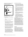
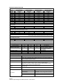
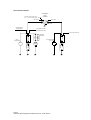
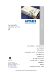
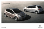
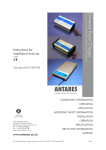
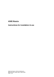
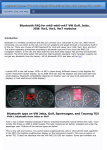
CE MARKING - INFORMATION
UNPACKING
MODE OF OPERATION
PRODUCT SPECIFICATION
INSTALLATION AND USE
APPLICATION NOTES AND TIPS
FM 37786
ISO 9001:2000
Antares (Europe) Limited
Chiltern Hill . Chalfont St Peter
Gerrards Cross . Bucks . SL9 9UQ . UK
Tel: +44 (0) 1753 890888
Fax: +44 (0) 1753 891260email:[email protected]
web site: http://www.antares.co.uk
PRODUCT LISTING
Instructions for
Installation and use
Automatic Split Charge System
PRODUCT LISTING
© 2004
TYPE APPROVAL - INFORMATION
This manual is applicable to the following products:
90311
ASC - 12V/140A (Std Split charge)
This family of products is type approved by the UK
Vehicle Certification Agency.
90313
ASC - 24V/140A (Std Split charge)
Type approval: e11022161
90314
ASC - 12V/200A (Std Split charge)
90315
ASC - 24V/200A (Std Split charge)
Non approved conditions of use
90323
ASC – 12V/140A (Remote Sense)
90324
ASC – 24V/140A (Remote sense)
70096
ASC – 12V/140A (Dual Sense)
70097
ASC – 24V/140A (Dual Sense)
70284
ASC – 12V/160A (Dual Sense)
70196
ASC – 12V/60A (Batt sense disabled)
70085
ASC – 24V/30A (Batt sense disabled)
70182
ASC – 24V/140A (Trailer sense)
This unit may be suitable for use in non-vehicular
applications, but it can only be supplied as a
component in this respect. If the unit is used in this
way, as a component part to build a battery charging
or similar apparatus, then this unit is supplied solely
on the condition that it is the responsibility of the
manufacturer of the apparatus to ensure that the
apparatus complies with the requirements of the
relevant legislation, and apply the CE marking should
it be required. In this case, this user manual does not
apply, and reference should be made to Antares
(Europe) Limited for any information required for
compliance with the legislation.
UNPACKING
Pack contents:
1 Antares Automatic Split Charge System
2 Instructions for installation and use.
3 Insulating boots for studs
Page 1
Automatic Split Charge User Manual, Part No. 13150 Issue 5
MODE OF OPERATION
Standard Version
The MAIN battery terminal is monitored by a
voltage sensing circuit which controls a switch
linking the MAIN and AUX studs. When
charging voltage is detected at the MAIN battery
terminal the switch closes. The switch remains
closed until the battery voltage falls to a level
which indicates that the MAIN battery is being
discharged.
90311
90313
70047
ASC 12V/140A (STD)
ASC 24V/140A (STD)
ASC 12V/160A (STD)
Dual Sense Version
This version should be is used where there is
also likely to be a charging source on the
auxiliary battery such as a battery charger or
second alternator. Charging voltage on either
battery will be detected and will cause the unit
to link both batteries. It is installed in exactly the
same way as the standard unit. Warning:
Cranking the engine whilst a charging source is
present on the auxiliary, may cause high
currents to flow through the unit, which may
cause damage.
70096
70097
70284
90314
90315
ASC 12V/140A (DUAL SENSE)
ASC 24V/140A (DUAL SENSE)
ASC 12V/160A (DUAL SENSE)
ASC 12V/200A (DUAL SENSE)
ASC 24V/200A (DUAL SENSE)
Remote Sense Version
This version should be specified where the split
charge cannot be sited close to the primary
battery. It is installed in exactly the same way
as the standard unit. The additional red sense
wire should be connected directly to the remote
primary battery positive terminal. Note that
connecting this to the main input stud reverts
the unit to the standard auto split charge.
90323
90324
ASC 12V/140A (REMOTE SENSE)
ASC 24V/140A (REMOTE SENSE)
Battery Sense Disabled Version
This version should be used where the auxiliary
battery is commonly fully discharged in
operation. It is installed in exactly the same way
as the standard unit. Note that the battery
sense is a safety feature. It protects the
auxiliary system by preventing closure into a
short circuit on the auxiliary or into a damaged
or dead battery. Please note that regular full
discharge of a lead acid battery is detrimental to
its life. We would strongly recommend that
some form of low voltage protection be applied
to the auxiliary battery.
70196
70085
ASC 12V/60A (BATT SENSE DIS)
ASC 24V/30A (BATT SENSE DIS)
Trailer sense version
This version should be used where the ASC is
to be fitted to a trailer. The unit has voltage
thresholds set to allow for distribution losses.
70182
ASC 24V/140A (TRAILER SENSE)
INSTRUCTIONS FOR INSTALLATION AND
USE
Application
The Automatic Split Charge unit protects the
main starting battery from discharge by auxiliary
loads on vehicles embodying dual battery
systems.
Where three batteries are required two ASC
units may be "cascaded" to prioritised first the
main battery then the auxiliary battery 1 and
then auxiliary battery 2. The units are connected
between the main battery and auxiliary 1 and
between auxiliary 1 to auxiliary 2.
Alternatively two ASC units can be used in
parallel, connected between the auxiliary 1 to
main battery and auxiliary 2 to main battery.
Here the main battery will be protected from
discharge by the auxiliary loads, however both
auxiliary batteries will receive charge equally.
The unit is suitable for under-bonnet mounting,
but must be protected from road spray and
engine fluids, particularly screenwash.
IMPORTANT SAFETY INFORMATION
Please read and observe the installation
instructions, particularly with regard to cable
sizing.
Operation
This unit is fully automatic in operation; no user
intervention is required.
Typical Installation
Connections and indicators
The Automatic Split Charge system is equipped
with two 8mm or 10mm power studs, plus a low
current ground wire, coloured blue. The remote
sense version also has a red wire. In a normal
installation the ‘MAIN’ stud should be routed to
the vehicle engine start battery positive
terminal. This is the battery fed directly from the
main vehicle alternator. The ‘AUX’ stud
connects to the second battery positive
terminal. The cables used should be sized to
carry the maximum current available from the
main or second alternator, whichever is greater.
The blue wire should be connected to the main
battery negative terminal or to the vehicle
chassis (provided the battery is also connected
to chassis). The red remote sense wire (when
used) should connect to the main battery
positive terminal. Insulating boots are
Page 2
Automatic Split Charge User Manual, Part No. 13150 Issue 5
provided, and should be used to cover the stud
terminals on the unit. The green lamp
illuminates when both batteries are linked
together by the split charge unit.
APPLICATION NOTES AND TIPS
•
Except for the 200 amp models, the ASC
will not close if it does not sense a battery
on the auxiliary stud unless battery sense is
disabled. The battery voltage needs to be
3V or above (except battery sense disabled
versions).
•
When connecting battery chargers, connect
to the main stud if you require charging of
both batteries. You do not need multioutput battery chargers. The system will
automatically prioritise the battery
connected to the main stud. For 200 amp
models, the charger may be connected to
either stud; whichever is required to be
prioritised.
•
To optimise the charging of the auxiliary
battery, locate the ASC as close to the
main battery as feasible using large cables
to minimise volt-drop.
•
You will need the “dual sense” version if
you intend to provide charging to the
auxiliary system directly via a second
alternator or a battery charger and want
these sources to charge the main battery.
(Note: All 200 amp models are dual sensed
as standard).
Stud assembly sequence:
Do not remove inner securing nut
Maximum torque 8 N-m
Cable ring terminal
Testing & Commissioning
After completion of the installation you should
check the following:
1.
Power stud nuts are tight, recommend 8Nm
max
2.
Remote sense wire (if used) is connected
correctly
3.
Blue ground wire is connected
4.
With the engine off, the indicator should not
be illuminated (Note: 200 amp models - the
indicator remains on for approximately 20
seconds after activation).
5.
Start the vehicle or apply a battery charging
voltage. The indicator should show that the
batteries are linked. This may take time as
the main battery may be discharged and /or
there may be a load on the primary system.
6.
If linking does not occur then there may be
insufficient voltage on the main stud check
table above or the auxiliary battery is not
present or discharged below 3V.
7.
Stop the vehicle or remove charging
source. The unit should unlink. If there is
no load on the battery the “plate” voltage
can sometimes remain high. If this occurs
apply a load such as headlights and check
that the system unlinks. (Note: 200 amp
models - the system remains linked for
approximately 20 seconds after activation).
Cyclic switching of the unit will occur if the
auxiliary battery is discharged and a load is
placed on the auxiliary system that exceeds the
capability of the charging source
(alternator/battery charger). This is caused by
the unit detecting that the additional current is
being drawn from the start battery and will
disconnect the auxiliary system and loads. The
main battery voltage will recover and allow the
auto split charge to attempt to reconnect
thereby repeating the cycle. This condition will
not cause short term damage to the unit and is
the unit working correctly to protect the main
battery from discharge. However if this situation
persists we would recommend that the power
balance on the vehicle is reviewed. Please call
Antares application engineering for assistance.
WARRANTY
The split charge comes with a full parts and
labour 'return to base warranty, held for two
years from the date of invoice. Please
telephone Antares first to confirm that the
problem lies with the unit and obtain a Returns
Authorisation Reference. Units will normally be
repaired or replaced, and shipped within 5
working days of receipt, subject to availability of
parts. Full details of the warranty provisions are
contained in our 'Terms and Conditions of Sale'.
Page 3
Automatic Split Charge User Manual, Part No. 13150 Issue 5
PRODUCT SPECIFICATION
MAIN stud transfer voltages:
Part
number
90311
90313
90314
90315
70047
70085
70096
70097
70182
70196
70284
Closing voltage,
minimum
12.90
25.60
13.09
26.16
12.90
25.60
12.90
25.60
25.80
12.90
12.90
Closing voltage,
maximum
13.50
26.80
13.63
27.23
13.50
26.80
13.50
26.80
26.90
13.50
13.50
Opening voltage,
maximum
13.10
25.80
12.91
25.79
13.10
25.80
13.10
25.80
24.00
13.10
13.10
Opening voltage,
minimum
12.50
24.70
12.40
24.78
12.50
24.70
12.50
24.50
23.00
12.50
12.50
13.63
27.23
12.91
25.79
12.40
24.78
AUX stud transfer voltages:
200 amp models:
90314
90315
13.09
26.16
AUX stud transfer voltages:
Other models, MAIN stud at nominal voltage, 12 or 24V
70096
70097
70284
13.2
25.5
13.2
13.8
26.6
13.8
Note: for these models, AUX stud thresholds depend on MAIN stud voltage
Overvoltage disconnect:
70047
70284
16.5 volts max
16.5 volts max
Current ratings:
Continuous Current
-current de-rated to
Switching current, make
Switching current, break
140
100
300
70*
160
120
300
70*
200
160
300
70*
Power draw, closed
Power draw, open
Power draw, open
5
24
0
10
24
0
10
90
90
Amps @ 20°C
Amps @ 85°C
Amps 1s max
Amps max *derated on battery
sense disabled to 60A@12V
and 30A @24V
Watts (typical)
milli watts main stud
milli watts aux stud
Environmental Ratings:
Protection
IP66 epoxy coated electronics, aluminium enclosure, detergents must be avoided
Temperature range
-10°C to + 85°C, with current derating as above (Survival –25°C to + 90°C)
0-100% with condensation and occasional water spray, but contact by detergents
must be avoided to prevent corrosion
Humidity
Enclosure
Dimensions
140 amp models: footprint 67mm x 140mm, including flanges.
160 & 200 amp models: footprint 134mm x 140mm, including flanges.
Height 34mm (+ 20mm for studs). 200 amp models: 54mm (+30mm for studs)
Fixings on 127mm centres, 4mm clearance holes.
Weight
Less than 1kg
Indicators
Green LED illuminates when contacts are closed
MAIN BATTERY
Connections
8mm stud, or 10mm stud on 200 amp models
AUX BATTERY
8mm stud, or 10mm stud on 200 amp models
GROUND
1m length blue wire, 1mm2
REMOTE
1m length red wire, 1mm2
Page 4
Automatic Split Charge User Manual, Part No. 13150 Issue 5
APPLICATIONS DIAGRAM
CHARGE INDICATOR LAMP
ON = SPLIT CHARGE RELAY CLOSED
AUTOMATIC
SPLIT
CHARGE
"MAIN" STUD
"AUX" STUD
BLUE WIRE
CHARGER INPUT
(IF REQUIRED)
IGNITION, & OTHER
PRIMARY CIRCUITS
Page 5
Automatic Split Charge User Manual, Part No. 13150 Issue 5
(AUX)
(AUX)
ENG.
START
BATTERY
2nd ALTERNATOR
(IF FITTED)
BATTERY
(STARTER)
ALT.
BATTERY
STARTER
SOLENOID
(STARTER)
MAIN
ALTERNATOR
BATTERY
AUXILIARY CIRCUITS
ALT.
Antares (Europe) Limited
Chiltern Hill
Chalfont St Peter
Gerrards Cross
Buckinghamshire
SL9 9UQ UK
www.antares.co.uk
Tel: +44 (0) 1753 890888
Fax: +44 (0) 1753 891260
❑ PRODUCT RETURNS FORM M
❑ ADVANCE REPLACEMENT RETURNS FORM
Date
(TICK BOX ABOVE TO INDICATE TYPE OF RETURN)
PLEASE USE THIS FORM TO ACCOMPANY RETURNS TO ANTARES (EUROPE) LIMITED. This will enable
us to expedite your repair/return more efficiently. If you have your own return form, please attach it to
this form. After receipt of your return we will either repair or replace the unit if within our warranty. If
outside our warranty, we will provide a written quotation for repair/replacement. Please note that in the
case of a ‘no fault found’ or the repair does not proceed, then a charge of £25 ex VAT and return
carriage (if required) is payable. Goods arriving without suitable paperwork will take longer to process.
Contact
Company Name
Delivery Address (for return)
Part Number
Serial Number
Product Description
Vehicle Type
Registration/your reference
Contact Fax
Contact Tel
Reason for return
(
(
(
(
(
(
(
)
)
)
)
)
)
)
Advance replacement returned for credit against invoice ..… RA ………
Incorrect supply
Please repair under warranty (Invoice date ……/……/……)
Please quote for repair
Please repair – purchase order attached ( )
Not required (note there may be a restocking charge)
Unit for reconditioning (advance replacement RA# ………………)
Description of observed fault and additional relevant information
continued on separate page ( )
Form 040 Issue 8 26.07.04