1
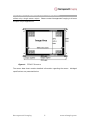
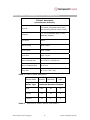
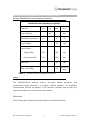
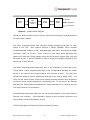
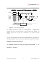
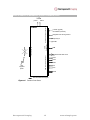
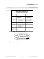
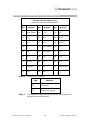
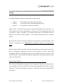
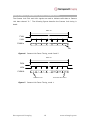
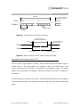
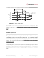
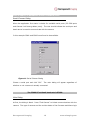
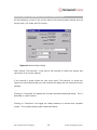
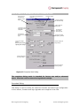
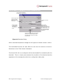
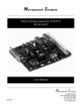
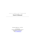
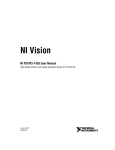
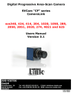
User’s Manual and Reference Guide
DIGITAL CAMERA MODULE: FFM4027D/Multi
June 2004
Narragansett Imaging 51 Industrial Drive North Smithfield, RI 02896
Tel: (401) 762-3800 Fax: (401) 767-4407
www.nimaging.com
USER’S MANUAL & REFERENCE GUIDE: FFM4027D/Multi
Table of Contents
Introduction .................................................................................................. 3
FFM4027 Overview ...................................................................................... 3
Features .................................................................................................... 3
Applications................................................................................................ 4
CCD Image Sensor ...................................................................................... 4
Camera Specifications and Operating Conditions .............................................. 7
Design ....................................................................................................... 7
Electronics............................................................................................... 7
Firmware................................................................................................10
Mechanics ..............................................................................................10
Camera Interfaces ........................................................................................11
Electrical Interfaces ....................................................................................13
Timing.........................................................................................................15
Camera Link Timing....................................................................................15
Integration and Timing Control (ITC) ............................................................17
Windows Application......................................................................................18
Serial Chooser Dialog..................................................................................19
Main Dialog ...............................................................................................19
Download Dialog ........................................................................................21
Narragansett Imaging
2
www.nimaging.com
USER’S MANUAL & REFERENCE GUIDE: FFM4027D/Multi
Introduction
This document provides instructions for the use of the FFM4027D/Multi and its
attendant software, describes its construction, and specifies its capabilities.
Readers are encouraged to consult related documentation for more information.
These include:
•
FFM3020D/Multi Hardware Manual and Programmer’s Guide, Narragansett
Imaging
•
FTF4027C Full Frame CCD Image Sensor Data Sheet, Dalsa Professional
Imaging
FFM4027 Overview
The FFM4027D/Multi is a high-performance 11 Mega-pixel CCD camera.
It offers
high speed and high dynamic range imaging, simple interfacing to and frame
grabbers and peripheral equipment, and provides numerous features intended to
facilitate its use in diverse and demanding applications.
Features
•
•
FTF4027 CCD image sensor:4k x 2.6k resolution,
o
100% fill factor,
o
progressive scan,
o
monochrome or color (standard Bayer pattern),
o
9um x 9um square pixels,
o
35mm compatible format.
25 MHz pixel rate.
Narragansett Imaging
3
www.nimaging.com
USER’S MANUAL & REFERENCE GUIDE: FFM4027D/Multi
•
1.6 Hz frame rate using single sensor output.
•
User adjustable analog gain and offset control.
•
Full 12-bit dynamic range.
•
User programmable digital Look-Up Table (LUT).
•
Defective column substitution.
•
Camera Link frame grabber interface.
•
Flexible operating modes:
•
o
continuous or external trigger,
o
internal or external integration control,
o
vertical binning.
Field upgradeable firmware and programmable logic.
Applications
The FFM4027D/Multi serves imaging applications that require very high resolution
and fast image acquisition. Its ability to resolve objects within high contrast scenes
together with its 35mm image format make this the ideal camera for digital film
scanning, aerial photography, scientific imaging, and medical imaging. Further, the
modular construction of the FFM4027D/Multi makes it suitable for OEM product
platforms that do not require external housing components, while its Camera Link
interface and simple operation ease its integration with the user’s equipment.
CCD Image Sensor
The FFM4027D/Multi employs a Dalsa FTF4027 CCD image sensor.
Either a
monochrome or color (RBG Bayer pattern) version can be installed.
The FTF4027 sensor can operate with one, two, or four outputs. This allows the user
to balance frame rate against complexity, power draw, and required frame grabber
bandwidth. The FFM4027D/Multi is designed to take advantage of the sensor’s multioutput capability.
For example, multiple analog processors and digitizers can be
incorporated and the digital processing features (LUT, column substitution) can be
programmed uniquely for each output. However, the current version of the camera
Narragansett Imaging
4
www.nimaging.com
USER’S MANUAL & REFERENCE GUIDE: FFM4027D/Multi
utilizes only a single sensor output. Please contact Narragansett Imaging to discuss
multiple-output applications.
Figure 1. FTF4027 Structure
The sensor data sheet contains detailed information regarding the sensor. Abridged
specifications are presented below.
Narragansett Imaging
5
www.nimaging.com
USER’S MANUAL & REFERENCE GUIDE: FFM4027D/Multi
FTF4027 Description
(monochrome and color)
Format
Full-frame, progressive scan with
anti-blooming and full sensor reset.
Outputs
1, 2, or 4 (mirrored, split, or four
quadrant readout)
Fill Factor
100%
Active Pixels
4008 x 2672
Total Pixels
4056 x 2684
Pixel Size
9 µm x 9 µm
Active Optical Size
36.072 mm x 24.048 mm
Active Diagonal Size
43.40 mm
Chip Size
38.5 mm x 25.7 mm
Table 1. FTF4027 Sensor Description
Sensor Grade
Defect Type
Pixel
Table 2.
Economy
Industrial
High
Maximum Number of Defects
100
50
25
Cluster
24
12
6
Column
12
1
0
Monochrome Sensor Blemish Specification
Narragansett Imaging
6
www.nimaging.com
USER’S MANUAL & REFERENCE GUIDE: FFM4027D/Multi
Camera Specifications and Operating Conditions
FFM4027D/Multi Operating Conditions
Parameter
Min.
Pixel Frequency
Operating Temperature
Typ.
Max.
Units
25
MHz
10
40
°C
6
28
V DC
Trigger Mode
200
850
mA
Continuous Mode
210
900
mA
Video Gain
0
36
dB
Black Level Offset
0
25
% (of full
scale)
Input Voltage
Input Current
Table 4.
FFM4027D/Multi Operating Conditions
Design
The
FFM4027D/Multi
employs
precise,
low-noise
analog
electronics
contemporary digital elements in a compact, modular package.
and
An embedded
microcontroller controls all aspects of the camera’s operation and provides the
camera’s interface to the Camera Link serial channel.
Electronics
The following figure illustrates the basic design of the FFM4027D/Multi.
Narragansett Imaging
7
www.nimaging.com
USER’S MANUAL & REFERENCE GUIDE: FFM4027D/Multi
USB
Sensor
Board
.
.
Video
Processing
Board
.
.
Timing
Board
.
.
Power
Board
CameraLink
CameraLink
Figure 2. Camera Block Diagram
The Sensor Board includes the CCD sensor, horizontal clock drivers, and adjustments
for sensor bias voltages.
The Video Processing Board has individual analog processing channels for each
output of the CCD.
Each channel employs a Philips TDA9965, which provides
correlated-double-sampling (CDS), adjustable gain and offset, and analog-to-digital
conversion (ADC) at 25 MHz.
Clock circuitry on the Video Board generates the
camera’s 50 MHz and 25 MHz master clocks and the precisely aligned CDS, ADC and
horizontal clocks. A Philips TDA9991 is used to supply the voltages required by the
sensor and its clock drivers.
The Video Processing Board passes one, two, or four channels of 12-bit video to the
Timing Board. Dense programmable logic on the Timing Board manages the overall
timing of the camera and synchronization with external sources.
The logic also
controls the defective column substitution and the in-line look-up tables (LUT). The
LUTs, one per sensor output, allow simple video processing functions such as gamma
correction, sensor output equalization, thresholding, etc. In the case of four channel
operation the Timing Board multiplexes four video channels to two, allowing the use
of a single Camera Link connection.
Processed and multiplexed data from the Timing board passes to the Power Board’s
Camera Link interface.
Synchronization signals to/from external equipment are
sent/received via the Power Board, as well.
The following figure illustrates the video processing functions.
Narragansett Imaging
8
www.nimaging.com
USER’S MANUAL & REFERENCE GUIDE: FFM4027D/Multi
Video Board
Timing Board
25 MHz
Current Configuration is
for single output
operation, so no signal
is present here
Analog video
from sensor
12
Power Board
50 MHz
12
12
TDA9965
LUT A
TDA9965
Column Sub.
Logic
LUT Cntrl
Logic
Camera
Link
TDA9965
LUT B
TDA9965
DVAL,FVAL
CDS Clocks
Vertical Clocks
Sensor Timing and
Voltage Control
External Timing Control
Timing
Figure 3. Video Processing Channels
The camera’s microcontroller resides on the Timing Board.
A serial peripheral
interface (SPI) within the microcontroller is used to program the TDA9965 and
TDA9991 devices, while its serial port is dedicated to the Camera Link serial
interface.
Note that the microcontroller firmware and the programmable logic configuration are
both field upgradeable via the Camera Link serial port.
This facilitates custom
applications and future feature enhancements. The Windows application provided by
Narragansett Imaging includes this facility.
The Power Board includes the Camera Link transmitter and connector, +12 volt
(nominal) input power connections, +5 and +3.3 volt power supplies, and
connections for external I/O.
Narragansett Imaging
9
www.nimaging.com
USER’S MANUAL & REFERENCE GUIDE: FFM4027D/Multi
Firmware
The microcontroller has in-circuit reprogrammable code storage memory.
The
memory can be reprogrammed via the Camera Link serial port. This same memory
is used for storing the configuration of the camera’s programmable logic and is field
reprogrammable as well.
These features facilitate custom applications and future
enhancements.
All programmable settings are accessed via the Camera Link serial interface and all
settings can be queried for their current state.
Both factory-original and user-
defined default settings are stored in the camera in non-volatile memory.
A simple ASCII protocol is used to communicate with the camera via the Camera
Link serial interface.
This is described in the document FFM3020D/Multi Hardware
Manual and Programmer’s Guide. The protocol is compatible with Camera Link serial
port drivers offered by frame grabber manufactures. Narragansett’s FFM/Multi
Windows application currently works with National Instruments and Bitflow frame
grabbers.
Other frame grabbers can be easily adapted.
Further, Narragansett
makes available the application’s C++ source code for those users wanting to
develop their own control software.
The FFM4027D/Multi employs an 8051 8-bit microcontroller with a built-in USB
interface.
While the USB interface is not used for controlling the camera or
transferring images, it is helpful for firmware development. Microcontroller firmware
can be developed using one of many popular C compilers/debuggers available for the
8051 family.
Mechanics
The Video Processing, Timing, and Power Boards attach in a pancake manner using
mezzanine connectors.
Narragansett Imaging
The Video and Sensor Boards connect via two flex cable
10
www.nimaging.com
USER’S MANUAL & REFERENCE GUIDE: FFM4027D/Multi
assemblies and miniature coaxial cables.
The non-rigid connection of the Sensor
board allows mounting schemes that facilitate optical alignment.
All the external electrical connections occupy one edge of the Power Board and each
employs a right-angle connector.
Camera Interfaces
This section describes the connections to the camera.
The figure 4 illustrates the
FFM4027D/Multi’s interfaces.
Narragansett Imaging
11
www.nimaging.com
USER’S MANUAL & REFERENCE GUIDE: FFM4027D/Multi
LEDs
status
+12VDC (typical)
+6/+28VDC (min/max)
Integration and Timing Control
Output Sync.
+5VDC
Image Sensor
USB
Connector
FFM4027
Power and I/O Connector
power
USB
5
Camera Link Connector
Video Data and Clock
User
supplied
optics
FVAL
LVAL
DVAL
CC1
CC2
Serial
Denotes differential signal
Figure 4. Camera Interfaces
Narragansett Imaging
12
www.nimaging.com
USER’S MANUAL & REFERENCE GUIDE: FFM4027D/Multi
Electrical Interfaces
Power and I/O Connector (J2)
Connector type: AMP 749798-1
Pin
Function
Notes
15
Output Sync
(output)
TTL, for external
strobe, etc.
13
+5 V DC (output)
50 mA maximum
1,6,7
+12 V DC (input)
Integration/Timing
Control (input)
11
2,3,4,5,8,9,
10,12,14
Table 5.
TTL
GND
Power and I/O Connector Pin-out
15
11
10
6
5
1
Figure 5. Power and I/O Connector
Narragansett Imaging
13
www.nimaging.com
USER’S MANUAL & REFERENCE GUIDE: FFM4027D/Multi
Camera Link Connector (J1)
Connector Type: 3M 10226-55G3VC
Pin
Symbol
Pin
1
Inner Shield
10
CC2+
19
X3+
2
X0-
11
CC3-
20
SerTC-
3
X1-
12
CC4+
21
SerTFG-
4
X2-
13
Inner Shield
22
CC1+
5
Xclk-
14
Inner Shield
23
CC2-
6
X3-
15
X0+
24
CC3+
7
SerTC+
16
X1+
25
CC4-
8
SerTFG+
17
X2+
26
Inner Shield
9
CC1-
18
Xclk+
Table 6.
Symbol
Symbol
Camera Link Connector
LED
Table 7.
Pin
Function
D3
Camera OK
D4
Readout in progress
LED Indicators (LEDs are internal and are not accessible in
housed camera configuration)
Narragansett Imaging
14
www.nimaging.com
USER’S MANUAL & REFERENCE GUIDE: FFM4027D/Multi
Timing
The FFM4027D/Multi supports three modes of frame timing:
•
Mode 0:
full resolution, externally triggered (ITC);
•
Mode 1:
2x vertical binning, externally triggered (ITC);
•
Mode 2:
full resolution, continuous framing.
Modes 0 and 1 have the frame rate and exposure controlled via the ITC input. In
these cases it is the user’s responsibility to provide an ITC with appropriate high and
low periods.
Mode 1 provides a 2x vertical binning (pairs of horizontal lines are
binned in the sensor’s output register).
ITC timing is described further in a latter
section.
Note that ITC control can also be provided via the Camera Link serial interface. This
feature is described in the FFM3020D/Multi Hardware Manual and Programmer’s
Guide.
Mode 2 has the camera running in an open-loop manner at its maximum frame rate,
with an integration (exposure) period of one horizontal line time.
Note that
immediately before the integration period one horizontal line time is used to reset
the CCD sensor. Also, several line times are required for removing the dummy lines
within the CCD sensor.
Camera Link Timing
The timing of valid data in modes 0 and 2 appear the same to the Camera Link
frame grabber, both have 2672 valid lines each containing 4008 valid pixels. Mode 1
has pairs of lines binned together resulting in 1336 valid lines each containing 4008
valid pixels.
Narragansett Imaging
15
www.nimaging.com
USER’S MANUAL & REFERENCE GUIDE: FFM4027D/Multi
The Camera Link FVAL and LVAL signals are used to indicate valid data on Camera
Link data channel “A.”
The following figures describe the Camera Link timing in
detail.
486.1 ms
FVAL
LVAL
CHAN A
0
1
2
2669
2670
2671
line #
Figure 6. Camera Link Frame Timing, mode 0 and 2.
259.1 ms
FVAL
LVAL
CHAN A
0
1
2
1333
1334
1335
binned lines 2670 & 2671
binned lines 0 & 1
Figure 7. Camera Link Frame Timing, mode 1.
Narragansett Imaging
16
www.nimaging.com
USER’S MANUAL & REFERENCE GUIDE: FFM4027D/Multi
160.32 µs
21.60 µs (modes 0,2)
33.64 µs (mode 1)
LVAL
line n
CHAN A
0
line n+1
1
4006
4007
0
pixel column #
40.00 ns
(25 MHz)
Figure 8. Camera Link Line Timing, all modes.
3.456 ms (mode 2)
(variable in modes 0 and 1)
19.56 µs (modes 0,2)
31.60 µs (mode 1)
2.04 µS
FVAL
LVAL
end of frame
beginning of frame
Figure 9. Start of Frame / End of Frame Timing, all modes.
Integration and Timing Control (ITC)
The ITC input to the FFM4027 is used to control frame rate and integration time in
modes 0 and 1.
The rising edge of ITC initiates a reset of the CCD sensor.
The
sensor reset period (one line time) is followed by the integration period. The falling
edge of ITC terminates the integration period and starts the process of reading out
the sensor.
The following figure illustrates ITC timing. Note the delay between the rising edge of
ITC and the beginning of the integration period during which the sensor reset takes
place.
Narragansett Imaging
17
www.nimaging.com
USER’S MANUAL & REFERENCE GUIDE: FFM4027D/Multi
182 µs (min)
0.1 - 182 µs
182 - 364 µs
28.38 ms (mode 0)
27.87 ms (mode 1)
ITC
(input)
19.56 µs (mode 0)
31.60 µs (mode 1)
EXT. SYNC
(output)
17.68 µs
FVAL
(output)
LVAL
(output)
beginning of
exposure
end of
exposure
Figure 10. ITC Timing, modes 0 and 1.
Note that ITC control can also be provided via the Camera Link serial interface. This
feature is described in the FFM3020D/Multi Hardware Manual and Programmer’s
Guide.
Windows Application
The application is coded in C++ using Microsoft’s Visual Studio. It has two primary
components; a camera driver class and a dialog class.
The driver class provides
access to the PC’s serial port (or Camera Link serial port) and low level control of the
camera. The driver class is described in the FFM3020D/Multi Hardware Manual and
Programmer’s Guide.
The application dialog provides a user interface for manipulating the various camera
parameters. It allows selection of a serial port, provide controls for all the camera’s
parameters, and present a means of reprogramming the microcontroller and Altera
CPLD.
Narragansett Imaging
18
www.nimaging.com
USER’S MANUAL & REFERENCE GUIDE: FFM4027D/Multi
Serial Chooser Dialog
When the application first starts it checks for available serial ports (PC COM ports
and Camera Link frame grabber ports). The user should indicate the serial port and
baud rate to be used to communicate with the camera.
In this example COM1 and COM2 were found to be available.
Figure 11. Serial Chooser Dialog
Choose a serial port and click “OK”.
The main dialog will appear regardless of
whether or not a camera is actually connected.
The FFM4027’s default baud rate is 57600
Main Dialog
At first, the dialog is blank. Press “Find Camera” to initiate communications with the
camera. The type of camera and the revision dates of the firmware and Altera logic
Narragansett Imaging
19
www.nimaging.com
USER’S MANUAL & REFERENCE GUIDE: FFM4027D/Multi
will be displayed, as well as the current state of the camera (basic settings such as
timing mode, LUT mode, and ITC source).
Figure 12. Minimal Main Dialog
After clicking “Find Camera” it may take a few seconds to locate the camera and
retrieve all of its current settings.
If the camera is power-cycled the user must press “Find Camera” to locate the
camera on the selected serial port and initialize the dialog with the camera’s current
settings.
Clicking on “Download” will display the firmware and Altera download dialog. This is
described in a latter section.
Clicking on “More/Less” will toggle the dialog between its minimal and complete
modes. The complete dialog mode is described below.
Narragansett Imaging
20
www.nimaging.com
USER’S MANUAL & REFERENCE GUIDE: FFM4027D/Multi
Click here to find
the camera and
retrieve its current
settings
The revisions of the firmware and
Altera logic
The type of camera
Click here to display
the download dialog
Click to toggle the
dialog mode
This pull-down menu
selects the Look-Up
Table Mode
This drop-down
menu selects
the timing mode
This selects the
source of the ITC
signal
Check this to enable
test pattern generation
Various CCD voltage
settings
Exercise caution when
adjusting these settings
Click here to apply the
voltage settings
Various analog video
processing settings
Click here to apply the
processing settings
Figure 13. Complete Main Dialog
The complete dialog mode is intended for factory use and/or advanced
users. Exercise caution when altering default settings.
Download Dialog
This dialog is used to modify the camera’s firmware and Altera logic configuration.
In this manner, firmware and logic upgrades can be applied in the field.
Narragansett Imaging
21
www.nimaging.com
USER’S MANUAL & REFERENCE GUIDE: FFM4027D/Multi
The progress bar will illustrate
the progression of the download
Enter the full path to an
appropriate firmware
file here, or use the
Browse button
Click this to search for
a file
Click to start the
downloading of the
selected firmware file. The
camera will store the file in
non-volatile memory. The
new firmware takes effect
the next time the camera
is turned on
Enter the full path
to an appropriate
Altera file here, or
use the Browse
button
Click to start the downloading of the selected
Altera file. The camera will store the file in
non-volatile memory and then re-configure
the Altera CPLD
Figure 14.Download Dialog
After a download completes a message box will appear to indicate success or failure.
The downloaded firmware will take effect the next time the camera is turned on.
Remember to click “Find Camera” afterwards.
The Altera CPLD will be re-configured with the downloaded file immedaitely after the
download. There is a slight pause between the completion of the download and the
appearance of the message box while the re-configuration takes place.
Narragansett Imaging
22
www.nimaging.com