1
FIPIO / FIPWAY Presentation
A
FIPIO Fieldbus
B
FIPWAY Cell network
C
Setup
D
Appendices
E
Index
F
G
___________________________________________________________________________
1
___________________________________________________________________________
2
A
FIPIO / FIPWAY Presentation
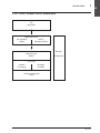
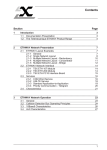
Contents
Section
Page
1 Introduction
1/1
1.1
Documentation Presentation
1/1
1.2
AEG Schneider Automation's FIPIO and FIPWAY Product Line
1.2-1 About the FIP Standard
1.2-2 The FIPIO Fieldbus
1.2-3 FIPWAY Cell Network (series 7 only)
1.2-4 FIPIO / FIPWAY in a FIP Architecture
1/2
1/2
1/3
1/4
1/5
2 Network Topology
2/1
2.1
General
2/1
2.2
Number of discrete TBX (IP65) supported by the drop cable and
TSX FP CFxxx 24VDC power cable
2/2
Types of Connection
2.3-1 Extension
2.3-2 Drop Connection (TSX FP CCxxx drop cable)
2.3-3 Drop Connection (TSX FP CA/CRxxx drop cable)
2.3-4 Combined Connection (extension and drop)
2.3-5 Network Architecture using a Repeater
2.3-6 Architecture with Several Repeaters
2/3
2/3
2/4
2/5
2/6
2/7
2/8
2.3
___________________________________________________________________________
A/1
E
A
FIPIO / FIPWAY Presentation
Section
Contents
Page
E
___________________________________________________________________________
A/2
Introduction
Section 11
A
1 Introduction
____________________________________________________________________________
1.1
Documentation Presentation
This documentation is designed for users implementing a FIPIO fieldbus or a FIPWAY
network. The complete documentation set is structured as follows :
This Reference Manual covering the FIPIO fieldbus and FIPWAY network :
• Operating principles,
• Network installation and testing principles,
• Operation, adjustment and diagnostic possibilities,
• Technical characteristics,
• Terminology including a glossary of terms.
Specialized User's Manuals are available for each device or family of devices that can
be connected to a FIPIO fieldbus or a FIPWAY network. The main points covered by
these manuals include :
• Device description,
• FIPIO fieldbus or FIPWAY network implementation or connection of each device,
• FIPIO fieldbus or FIPWAY network performance,
• Remote diagnostic functions via the network.
This document refers to the manuals required for the complete implementation of
the application. A list of these manuals is provided in the Appendix, part E section 3.
___________________________________________________________________________
A1/1
H
A
___________________________________________________________________________
1.2
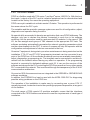
AEG Schneider Automation's FIPIO and FIPWAY Product Line
AEG Schneider Automation has developed two types of network architectures for
decentralizing peripherals, intelligent devices and services for long distance data
exchange. These architectures are as follows :
• The FIPIO fieldbus for sensors, preactuators and terminals for use with the TSX series
7 and APRIL® series 1000 PLCs,
• The FIPWAY economic single cell network.
The FIPIO fieldbus and the FIPWAY network are fully compatible with the FIP standard.
1.2-1 About the FIP Standard
FIP is a set of UTE standards that has been tailored to "real time" communication
requirements. This type of communication is needed for the implementation of reflex
automation systems.
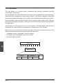
This standard is based on a three-layer communication system together with the
network management function. It complies with the special requirements of fieldbuses
and cell networks.
FIP is based on the principle of data broadcasting. Data exchange takes place as follows :
• A call is sent by the bus controller (called the bus arbiter) to all stations and is
addressed to a producer subscriber and all consumers concerned,
• A response is broadcast by this producer subscriber to all stations and can be used
by all consumer subscribers.
FIP accepts two types of application service :
• A distributed database (cyclic variables) which is exchanged periodically between
the devices connected to the network and does not require application programs. This
information is available to all consumers at the same time, thus providing data
coherence and facilitating synchronization between devices,
• A message handling system which, on request, sends messages in point-to-point
mode or in broadcast mode. This is very useful for configuration, adjustment,
diagnostics and maintenance of intelligent sensors and preactuators as well as for
operating and operator dialog functions.
These services are managed by a broadcast bus with a bus arbiter running on a
150-Ohm shielded, twisted pair.
___________________________________________________________________________
A1/2
Introduction
1
A
____________________________________________________________________________
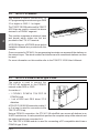
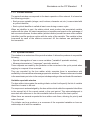
1.2-2 The FIPIO Fieldbus
FIPIO is a fieldbus used with TSX series 7 and April® series 1000 PLCs. With this bus,
the inputs / outputs of the PLC and its industrial peripheral can be decentralized and
located on the factory floor near the operating equipment.
FIPIO uses cyclic variables to refresh remote I/O status. This operation is performed at
the same rate as the PLC cycle.
The variables and the aperiodic message system are used for all configuration, adjust,
diagnostics and operator dialog functions.
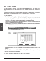
No special skills are needed to develop an application that uses FIPIO fieldbuses. The
designer only has to declare the devices connected to each bus in his software
workshop, like the procedure used for rack-mounted I/O modules. In the case of TBX
I/O, he then assigns each group of TBX channels to the appropriate PLC task. The
software workshop automatically generates the network operating parameters which
are then downloaded into the PLC. A series of screens will help the operator with the
configuration and adjustment of devices connected to the bus.
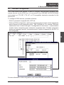
On series 7 equipment, during start-up or when maintenance is being carried out on the
installation, FTX 417 and FTX 507 programming terminals can be connected to any
point of the FIPIO bus. All the software workshop services are available immediately :
adjust, diagnostics, programming etc. The terminals can be connected to and disconnected from the fieldbus without having any effect on operation. If the programming
terminal is connected to dedicated address point 63, it can use the services of the
software workshops for the PLC controlling the FIPIO bus as well as for any other remote
PLC connected to the network. This is achieved through the transparency of the X-WAY
communication architecture.
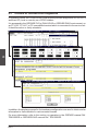
On a series 1000, the same services are integrated in the ORPHEE or ORPHEE-DIAG
software workshop.
In addition, the SYSDIAG tool can be used with the APRIL 5000 PLC for diagnosing
possible wiring problems on the FIPIO bus.
The operation of the installation is made easy by connecting one or more CCX 17
operator terminals, located as close to the operating equipment as possible, at any point
on the fieldbus.
The wide range of TBX remote I/O modules available, means that the interfaces
connected to the FIPIO fieldbus are tailored to meet the requirements of each type of
installation.
___________________________________________________________________________
A1/3
H
A
___________________________________________________________________________
1.2-3 FIPWAY Cell Network (series 7 only)
FIPWAY is the low-cost cell network that complies with the FIP standard and is built into
X-WAY communication architectures.
FIPWAY provides simple and efficient coordination between all the TSX series 7 PLCs,
from the TSX 17 micro-PLC through to advanced high performance processors such as
the TSX 107 and PMX 107. When connected to FIPWAY, FTX programming terminals
and CCX control and supervision systems make it easier to implement and use the
network.
FIPWAY starts up automatically as soon as the devices have been switched on because
of its pre-defined operating mode and the use of a floating bus arbiter. It does not have
to be configured first.
FIPWAY supports all X-WAY services :
• Distributed database : common words (COM) exchanged cyclically among all the
stations without the need for application programs and used at each point as local
variables,
• UNI-TE industrial message handling system for equal level communication between
devices. It is used for control, adjustment, diagnostics and program transfer functions,
• Application-to-application communication between all the devices connected to the
network via standard text function blocks or high priority blocks such as telegrams,
• Multiple network transparency through the X-WAY addressing system which allows
a terminal connected to a PLC at any point of an installation to access any device on
the network as if it were physically connected to it.
Since the programming interfaces remain unchanged, a TELWAY installation can run
FIPWAY without modifying the application programs if an extension is mounted.
As FIPWAY is fully integrated into the X-WAY environment, initially separate cell
networks can be connected later in a workshop by a larger network such as MAPWAY
or ETHWAY without modifying the application programs.
FIPWAY also supports all the X-WAY diagnostics and network management tools :
• For simple installations, SYSDIAG software does a basic quick diagnostic of the
network and connected devices,
• Larger installations implementing a considerable number of devices or several
networks will be configured and documented using PL7-NET software. They will be
monitored in the operating and maintenance phases by NETDIAG software.
___________________________________________________________________________
A1/4
Introduction
1
A
____________________________________________________________________________
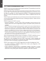
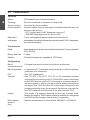
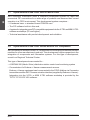
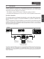
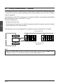
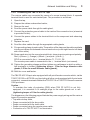
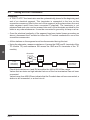
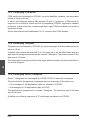
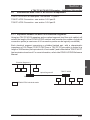
1.2-4 FIPIO / FIPWAY in a FIP Architecture
FIP
Application
∇
∇
Application Layer
FIP Variables
(MPS)
UNI-TE
Message System
∇
∇
Network
Network Layer
Management
XWAY
Link Layer
Variable
Exchanges
Message
Transfers
Physical Layer
Shielded twisted pair
1 Mb/s
___________________________________________________________________________
A1/5
H
A
___________________________________________________________________________
___________________________________________________________________________
A1/6
Network Topology
Section 22
A
2 Network Topology
____________________________________________________________________________
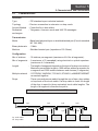
2.1
General
In order to create a FIPIO or FIPWAY architecture which will allow the different devices
to be connected, AEG Schneider Automation can provide the following :
• TSX FP CAxxx trunk cable, available in lengths of 100, 200 or 500 meters,
• TSX FP CRxxx trunk cable, available in lengths of 100, 200 or 500 meters,
• TBX FP CFxxx remote power cable, available in lengths of 100, 200 or 500 meters,
for sealtight TBX modules,
• TSX FP CCxxx drop cable, available in lengths of 100, 200 or 500 meters for sealtight
TBX modules,
• TSX FP CE 030 cord for connecting the terminals,
• TSX LES 65 or TSX LES 75 connector for connecting the TSX series 7, model 40
PLCs,
• TSX FP ACC2 connector for extension or drop connection of the TSX 17 micro-PLCs,
• TSX BLP 01 connector for connecting the TBX remote I/O interfaces (IP20),
• TBX BLP 10 connector for connecting the sealtight TBX remote I/O interfaces (IP65),
• TBX BAS 10 connector for supplying sealtight TBX output modules,
• TSX FP ACC4 tap,
• TBX FP ACC10 tap (IP65),
• TSX FP ACC7 line terminator.
TSX FP CA xxx and TSX FP CC xxx cables can only be used for applications inside
buildings, in standard conditions.
TSX FP CR xxx and TSX FP CF xxx cables are used to set up installations out of doors
or in locations where they may be subject to harsh environmental conditions (chemical,
climatic or mechanical). For further details, see the table in part D, section 3.1, Installing
the cables.
Devices can be connected to a segment as follows:
• By extension with each device being connected to the previous one by the trunk cable
or by the remote power cable (IP65)
• By means of a drop line with each device being drop-connected to the trunk cable via
a TSX FP ACC4 or TBX FP ACC10 tap using either the TSX FP CCxxx drop cable,
the TSX FP CA/CRxxx trunk cable,
• Using a combination of the above which comprises devices connected by extension
and by drop cable.
___________________________________________________________________________
A2/1
H
A
___________________________________________________________________________
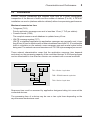
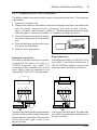
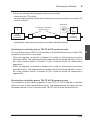
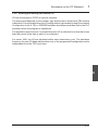
A FIPIO or FIPWAY network consists of one or more segments connected together
by repeaters.
The maximum length of a bus segment is 1000 meters and the maximum number
of stations per segment is 32 (plus any repeaters).
To connect more devices or for lengths greater than 1000 meters, TSX FP ACC6
electrical repeaters or TSX FP ACC8 optical repeaters must be used. The repeater
is connected to each segment by extension or using a drop cable.
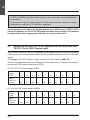
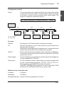
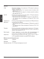
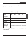
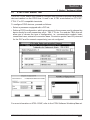
2.2
Number of discrete TBX (IP65) supported by the drop cable and
TSX FP CFxxx 24VDC power cable
The number of discrete TBX (IP65) depends on the length of the line in meters, the gauge
of the electrical conductors which make up the line cable and the precision of the power
supply.
The gauge used for the power supply conductors in this cable is AWG 18.
The various parameters are summarized in the two tables below. They are only valid for
the discrete TBX product references (IP65).
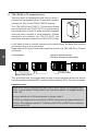
a) For a 24 V DC power supply at 5%
Number
of TBX
Length
of the line
in meters
1
2
3
4
5
6
7
8
9
10
318
157
103
76
60
49
44
38
31
27
b) For a 24 V DC power supply at 10%
Number
of TBX
1
2
3
4
5
6
7
8
9
10
Length
of the line
in meters
222
109
71
52
40
33
27
23
20
18
___________________________________________________________________________
A2/2
2
Network Topology
A
____________________________________________________________________________
2.3
Types of Connection
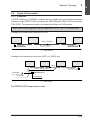
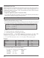
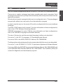
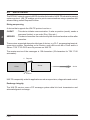
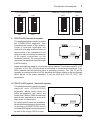
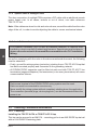
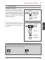
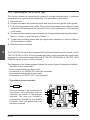
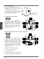
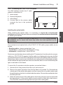
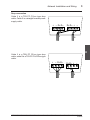
2.3-1 Extension
A FIPIO fieldbus or a FIPWAY network can be installed by direct station-to-station
extension using TSX FP CA/CFxxx cables for TBX (IP20) and TSX FP CRxxx cables for
TBX (IP65). The maximum length of a segment will then be 1000 meters.
Both ends of each segment must be fitted with a TSX FP ACC7 line terminator.
Example of an extension connection (IP20)
FIPIO / FIPWAY
Terminator
Terminator
Trunk cable
L ≤ 1000 meters
Example of an extension connection (IP65), on FIPIO only
FIPIO
TSX FP CFxxx cable
Terminator
Trunk cable
Terminator
TBX FP ACC10
Power supply
L ≤ 1000 meters
The TBX FP ACC10 tap must be used.
___________________________________________________________________________
A2/3
H
A
___________________________________________________________________________
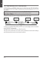
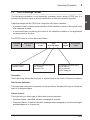
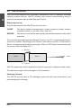
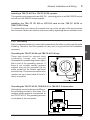
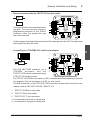
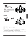
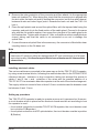
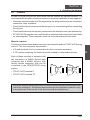
2.3-2 Drop Connection (TSX FP CCxxx drop cable)
A FIPIO fieldbus or a FIPWAY network can be installed by using TSX FP CA/CRxxx
trunk cables and TSX FP ACC4 taps. The stations are connected using drop TSX FP CCxx
drop cables.
Each segment must be fitted at both ends with a TSX FP ACC7 line terminator. The
maximum length of the segment is given by the following relation :
Lp + 3∑Ld ≤ 1000 m.
Example of a drop connection using the TSX FP CCxxx drop cable
Drop cable
FIPIO / FIPWAY
Terminator
Trunk cable
Ld
Terminator
Lp
In order to use sealtight TBXs (IP65) on FIPIO only, a power supply must be connected
to the TBX BLP 10 connectors.
The tap can be a TSX FP ACC4 or a TBX FP ACC10.
This type of drop connection can only be used for installations located inside buildings
and operating under normal environmental conditions.
___________________________________________________________________________
A2/4
2
Network Topology
A
____________________________________________________________________________
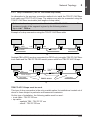
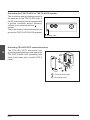
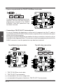
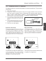
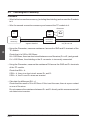
2.3-3 Drop Connection (TSX FP CA/CRxxx drop cable)
An alternative to the previous connection method is to install the TSX FP CA/CRxxx
trunk cable and TSX FP ACC4 taps. The stations can also be connected using the
TSX FP CA/CRxxx trunk cable (two lengths of drop cable).
Both ends of each segment must be fitted with a TSX FP ACC7 terminator. The
maximum length of the segment is given by the following relation :
Lp + ∑Ldi ≤ 1000 m.
Example of a drop connection using the TSX FP CA/CRxxx cable
Drop
cable
Ld1
Ld2
Trunk cable
Terminator
Terminator
Lp
Sealtight TBXs (IP65) are drop connected (on FIPIO only) using the TSX FP CA/CRxxx
trunk cable and the TBX FP CB100 remote power cable from TBX FP ACC10 taps.
Tap
Ld1
TSX FP CFxxx
cable
Ld2
Trunk cable
Power supply
Terminator
Terminator
TBX FP ACC10
Lp
TBX FP ACC10 taps must be used.
This type of drop connection is the only possible option for installations located out of
doors or those subject to particular environmental constraints.
On this type of installation, the following cables must be used :
• trunk cable : TSX FP CR xxx
• tap cable :
- sealtight TBX : TSX FP CF xxx
- others : TSX FP CR xxx
___________________________________________________________________________
A2/5
H
A
___________________________________________________________________________
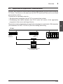
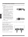
2.3-4 Combined Connection (extension and drop)
The three connection modes that have already been described can be combined on the
same installation. A combination of these types of connection can be used, for example,
to connect the devices in an electrical control cabinet to the network with one type of
cable etc.
Both ends of each segment must be fitted with a TSX FP ACC7 terminator. The
maximum length of the segment is given by the following relation :
Lp + ∑Ldi + 3∑Ldj ≤ 1000 m.
Example of a combined connection (IP20)
Terminator
Ldj
Ldi
Terminator
FIPIO / FIPWAY
Cabinet
Lp
Example (on FIPIO only) of a combined connection for sealtight TBXs (IP65)
TSX FP CFXXX cable
Power supply
TSX FP CFXXX cable
Trunk cable
Terminator
Trunk cable
Power supply
Terminator
Power supply
Lp
TSX FP ACC4 or
TBX FP ACC10
TBX FP ACC10
___________________________________________________________________________
A2/6
2
Network Topology
A
____________________________________________________________________________
2.3-5 Network Architecture using a Repeater
The use of a repeater makes it possible to increase the range of the network and/or to
increase the number of stations connected. Connection can also be made by extension,
drop cable or a by combining the possibilities.
Both ends of each segment must be fitted with a TSX FP ACC7 terminator. The
maximum length of each segment is 1000 meters (including drop cables). The
length of the trunk depends on the type of drop cable used (see sections 2.2-2 and
2.2-3).
Example of architecture
Terminator
Segment A
Repeater
Terminator
Segment B
Cabinet
Terminator
Further information relating to architectures using several repeaters can be found in
Appendix 4.1, part E.
___________________________________________________________________________
A2/7
H
A
___________________________________________________________________________
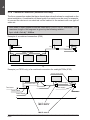
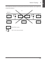
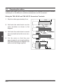
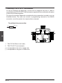
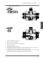
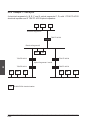
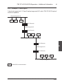
2.3-6 Architecture with Several Repeaters
It is also possible to cascade a maximum of four repeaters per segment in linear or tree
type architectures to increase the range of the network and/or to increase the number
of stations connected from 32 to a maximum of 64 (for all segments).
Segment 1
Segment 2
Segment 3
Segment 4
Optical
segment
Segment 7
Segment 5
Segment 6
FIPIO/FIPWAY station,
TSX FP ACC6 electrical repeater.
TSX FP ACC8 optical repeater.
___________________________________________________________________________
A2/8
Network Topology
2
A
____________________________________________________________________________
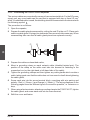
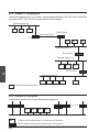
In an architecture that uses several repeaters (electrical and optical), only one path must
connect two stations.
NO
Segment 1
Segment 2
FIPIO/FIPWAY station,
TSX FP ACC6 electrical repeater
___________________________________________________________________________
A2/9
H
A
___________________________________________________________________________
___________________________________________________________________________
A2/10
A
FIPIO Fieldbus
Contents
B
Section
Page
1 Examples of FIPIO Architectures
1/1
1.1
General
1/1
1.2
Examples
1.2-1 Single Station Architecture
1.2-2 Multiple Station Architecture (Series 7 only)
1/2
1/2
1/3
2 Operating Principles
2/1
2.1
General
2/1
2.2
Characteristics
2/2
2.3
FIPIO Exchange Format
2/5
3 Connectable Devices
3/1
3.1
Processors
3.1-1 TSX and PMX Processors
3.1-2 APRIL 5000 Processors
3/1
3/1
3/2
3.2
TBX Remote I/O
3/3
3.3
TSX FPC 10 Module
3/4
3.4
TSX FPC 20 Module
3/5
3.5
TSX FPG 10 Module (series 7 only)
3/6
3.6
PCMCIA type III Cards
3/7
3.6-1 Module for FTX 417-40 Notebook or PC-compatible
3/7
3.6-2 Module for CCX 17 Operator Panel
3/7
3.6-3 Module for ATV 16 Variable Speed Drive
3/7
___________________________________________________________________________
B/1
FIPIO Fieldbus
Contents
B
Section
Page
3.7
Open Access of the FIPIO via a PCMCIA Card
3/8
3.8
Open Access of the FIPIO via the Built-in FIP Component
3/8
4 Services
4/1
4.1
Remote I/O service
4/1
4.2
UNI-TE Service
4/2
5 How to Connect a Device
5/1
5.1
First Start-Up of the Application
5/1
5.2
Adding a Device to an Existing Application
5/1
___________________________________________________________________________
B/2
Examples of FIPIO Architectures
Section 11
1 Examples of FIPIO Architectures
____________________________________________________________________________
1.1
General
Note :
In this document, the term segment means the part of the network between two repeaters or
bridges, the term network means all the segments with the same network address and the term
multiple network means an architecture comprising several interconnected networks.
The FIPIO fieldbus is used mainly for level 0 applications (controlling sensors and
actuators). With this bus, all or part of the automation control system can be located near
the production site (I/O modules, variable speed drives, identification systems, PCcompatible workshop terminals and operation and control system).
These applications are carried out by the set of devices that can be connected to the
FIPIO fieldbus :
•
•
•
•
•
•
•
•
•
•
•
•
TSX 7 modular PLCs and PMX 7 model 40 PLCs,
APRIL® Series 1000 PLCs,
TBX remote I/O modules (discrete and analog),
FTX 507 programming terminal,
FTX 417 programming terminal,
CCX 77 supervision and control systems,
PC terminal,
TSX 17 micro-PLC,
CCX 17 control panel,
ALTIVAR variable speed drives,
SEPAM 2000 distribution and monitoring system,
concentrators for Endress + Hauser measurement sensors.
FIPIO supports all the communication services required by automation personnel with
guaranteed I/O refresh time, network transparency and the UNI-TE message handling
system services :
• The dedicated exchanges on the FIPIO bus are exchanges of input channel acquisition
status variables and output channel commands. These exchanges are performed
cyclically without any intervention from the application program.
• Other data can also be exchanged on the FIPIO fieldbus such as remote device
configuration variables and UNI-TE messages (these services allow the bus arbiter
to send parameters to other devices).
The FIPIO fieldbus can be used in several ways :
• In a simple environment (single station), with Series 7 and Series 1000 PLCs,
• In a more complex environment (multiple station) where several FIPIO segments can
be connected in the workshop by a higher level local network such as ETHWAY (for
Series 7 only).
The various architecture possibilities are shown on the following pages.
___________________________________________________________________________
B1/1
B
___________________________________________________________________________
1.2
Examples
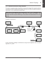
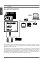
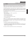
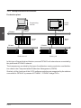
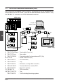
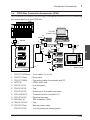
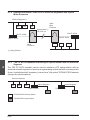
1.2-1 Single Station Architecture
Automation of a Production Line
B
FTX 507
(series 7
access only)
TSX 7
TBX
FIPIO
TBX
TBX
ATV
TBX
Cabinet
TSX 17
Sealtight TBXs
Delocalizing I/O means that the constituent parts of the automation system no longer
have to be installed in the PLC control cabinet and can be located near the operating
equipment on the factory floor
Decentralization of industrial operations favors the manufacture of modular machines
or ones which can be easily dismantled. This means that the best use can be made of
the preprocessing and diagnostics functions offered by intelligent sensors and
preactuators. Control and diagnostics systems (for Series 7 PLC only) can therefore be
set up in the heart of the installation where they are really useful.
___________________________________________________________________________
B1/2
Examples of FIPIO Architectures
1
____________________________________________________________________________
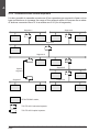
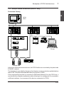
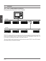
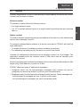
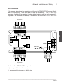
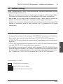
1.2-2 Multiple Station Architecture (Series 7 only)
Production Factory
B
CAPM
station
ETHWAY
CCX 57
TSX 7
FIPIO
TSX 7
TSX 7
TBX
ATV
Cabinet
TBX
FTX 507
TSX 17
Sealtight TBX
In this type of hierarchical architecture, the FIPIO fieldbus is connected by the plant-wide
ETHWAY network.
The transparency provided by this type of architecture carries production and distribution
data to the Computed-assisted Manufacturing System (CAM).
If the programming terminal is connected to dedicated address 63 on the FIPIO bus, it
can access the complete architecture without having to be configured (if connected to
a different address, it can access all the devices connected to FIPIO).
___________________________________________________________________________
B1/3
___________________________________________________________________________
B
___________________________________________________________________________
B1/4
Operating Principles
Section 22
2 Operating Principles
____________________________________________________________________________
2.1
General
A device on the FIPIO fieldbus is identified by its connection point.
The connection point number is the physical address of the device on the bus and takes
a value from 0 to 63.
Address 0 is reserved exclusively for the bus controller PLC.
Address 63 is allocated to the programming terminal. This dedicated address allows
this terminal to access the complete network architecture without having to be
configured first.
All the other addresses can be used by devices that can be connected to FIPIO, but
they must first be configured with programming software (for more information, see
section 5 or 6, Part D).
Bus arbiter
On a FIPIO bus at a given moment, a unique station authorizes data exchange : this is
the active bus arbiter which controls access to the medium.
The function of the bus arbiter is simple. It scrolls the list of messages to be sent and then
decides when the aperiodic exchanges of variables and messages requested will take
place.
The list of cyclic exchanges and the windows assigned for aperiodic traffic form a
macro-cycle. The continuous scanning of this macro-cycle is performed by the active
bus arbiter.
On a FIPIO bus, the macro-cycle is linked to the data exchange requirements of the
application program. This cycle will :
• Scan the status variables and the device command variables, taking into account the
need to update the PLC tasks,
• Assign a window for aperiodic exchange of variables for configuration, control and
diagnostics of remote devices (this window allows exchanges of five 128-byte
variables per second),
• Assign a window for aperiodic exchanges of messages which will be shared among
all the devices using the message system service (this window allows exchanges of
twenty 128-byte messages per second; this data-rate is 50 messages per second for
32-byte messages).
___________________________________________________________________________
B2/1
B
___________________________________________________________________________
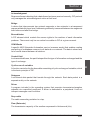
2.2
Characteristics
Structure
B
Nature
: FIP-standard open industrial fieldbus.
Topology
: Devices connected in extension or drop mode.
Access method
: Controlled by the bus arbiter.
Communication
: Communication is by the exchange of variables which the user can
access in the form of :
- PL7-3 object and X-WAY datagram for series 7,
- ORPHEE language words for series 1000.
Dedicated
exchanges
: Cyclic exchanges of status variables and remote I/O
exchanges commands (parameter variables and X-WAY datagrams
are also exchanged).
Transmission
Mode
: Base band physical layer on shielded twisted pair (French standard
NF C46 604).
Binary data-rate
: 1 Mb/s.
Medium
: Shielded twisted pair (impedance 150 Ohms).
Configuration
Nbr of
: 64 logical connection points for the whole architecture.
connection points
Nbr of segments : A maximum of 5 (cascaded) using electrical or optical repeaters
(maximum of 4 cascaded).
PLC
: One PLC at address 0.
Terminal
: One FTX 507, CCX 57/77, FTX 417 or PC-compatible terminal
connected to connection point 63. (Several PCs can be connected
to the FIPIO bus but only the PC connected to connection point 63
will have access to all the console functions without having to be
configured first. Once the other PCs have been configured in the
software workshop, they can access all the devices connected to
the FIPIO network up to the level of the bus controller PLC).
Length
: The length of a segment depends on the type of drops used.
Maximum length is 1000 meters without a repeater for a segment
and 5000 meters between end devices (5 segments).
Multi stations
(series 7
only)
: Network transparency is ensured with MAPWAY or ETHWAY.
___________________________________________________________________________
B2/2
Operating Principles
2
____________________________________________________________________________
Configuration (cont'd)
Drops
: These connections are made through the use of taps, drop cables
or loop-back of the trunk cable. If a drop cable is used, the length
of the drop is equal to three equivalent trunk cable lengths. The
length of a segment is therefore equal to :
L = sum of the Lpx + 3 x sum of the Ldx ≤ 1000 m
Lp1
Lp2
Ld1
Ld2
Lp3
Lp4
Lp6
Lp5
Ld3
Lp : trunk cable
Ld : drop cable
Services
Remote
I/O
: Exchanges of I/O channel status variables and output
channel commands in cyclic mode without any intervention from
the application program.
Remote device management (configuration etc.) in aperiodic mode
without any intervention from the application program.
UNI-TE
: Point-to-point request service with confirm, maximum of 128 bytes.
This service can be used by all the stations connected to FIPIO that
support this service.
Data integrity
: Control characters on each frame and message acknowledgment
(French standard NF C46 603).
Supervision
: The PLCs and their inputs / outputs (local or remote) are diagnosed
by one of the following terminals : FTX 507, CCX 7 FTX 417 or
PC-compatible, with SYSDIAG software for series 7.
ORPHEE, ORPHEE-DIAG software, as well as the ANALYZER
function in the SYSDIAG (DOS) tool for series 1000.
Maximum size of the data sent
Variables
: 128 bytes.
Messages
: 128 bytes.
Message data-rate : twenty 128-byte messages per second.
___________________________________________________________________________
B2/3
B
___________________________________________________________________________
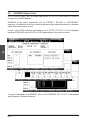
Task Network Cycle Time
B
Network cycle time corresponds to the time between two scans of the same module on
the bus. There are two cases. The application is either a single task application or a
multiple task operation (on series 7 only). The calculation for series 1000 is the same
as for the series 7 single task.
• Single task application (series 7 and series 1000)
For a single task application (guideline), the value of the network cycle time (Nct) in
milliseconds is obtained using the following formula :
Tcr = 1 + 0.5 x Number of TBX connection points in the application (*)
• Multiple task application (series 7 only)
For a multiple task application TBXs are configured in each of the tasks. The value of
the network cycle time of each of the tasks in milliseconds is obtained as follows :
Tcr_fast
= 1 +0.5 x Equivalent number of TBX connection points (*)
Tcr_mast = Tcr_fast / K
Tcr_aux
= Tcr_fast / K'
where :
K = Fast task cycle time / mast task cycle time,
K' = Fast task cycle time / auxiliary task cycle time,
Equivalent nbr of TBX
= Nbr of TBX configured in the fast task + (K x Nbr of TBX
configured in the mast task) + (K' x Nbr of TBX configured in the auxiliary task)
(*) for 1 and 5 TBX, the formula is : Nct = 1.5 + 0.5 number of TBX connection points
Example :
Cycle Time
number of TBX
K, K'
fast
10 ms
2
mast
40 ms
81/4
aux
120 ms
41/12
The equivalent number of connection points is :
2 + (1/4 x 8) + (1/12 x 4) = 4.33 rounded off to 5
Tcr_fast =
1 + (0.5 x 5) =
3.5 ms
Tcr_mast =
3.5 : 1/4 =
14 ms
Tcr_aux =
3.5 : 1/12 =
42 ms
___________________________________________________________________________
B2/4
2
Operating Principles
____________________________________________________________________________
2.3
FIPIO Exchange Format
The following information is not absolutely necessary when using a FIPIO bus. It is
provided for familiar users as a brief explanation of how the network operates.
B
A data exchange on the FIPIO bus comprises two frame transfers :
• A question frame containing the identifier of the variable to send or the source entity
of a message to send,
• A response frame containing the value of the identified variable or the application
message sent on the bus.
The FIPIO frame is broken down as follows :
Preamble
8 bits
Start Frame
6 bits
If question frame :
identifier value
Frame Control
1 byte
Data
0 to 262 bytes
If variable response frame :
I/O variables,
presence, etc.
FCS
2 bytes
End Frame
7 bits
If message response frame :
target address
source address
XWAY datagram
Preamble :
This 8-bit string allows the receivers to synchronize to the clock of the source station.
Start frame delimiter :
This start frame delimiter comprises six bits and allows the date link layer to locate the
start of its assigned data.
Frame control :
This byte tells you what type of frame has been exchanged :
• Question frame : identified variable, message or request,
• Response frame : identified variable, message acknowledged or not acknowledged,
acknowledgment or request etc.
___________________________________________________________________________
B2/5
___________________________________________________________________________
Data :
This field contains :
• The identifier value (two bytes) for a question frame,
B
• The value of the application variable (2 to 128 bytes) for an identified variable
response frame,
• A source address (three bytes), a target address (three bytes) and an X-WAY
datagram (128 bytes) for a message response frame,
• A string of identifiers for a request response frame (system service).
FCS (frame check sequence) :
These two bytes are used to check that the data exchange is performed correctly. The
control code is calculated by the source station and then sent after the data. The
receiving station recalculates the code and compares it with that received from the
source. If the two do not match, the message is refused by the target station.
End frame delimiter :
The end frame delimiter comprises seven bits and allows the data link layer to locate the
end of its assigned data.
___________________________________________________________________________
B2/6
Connectable Devices
Section 33
3 Connectable Devices
____________________________________________________________________________
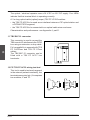
3.1
Processors
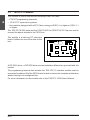
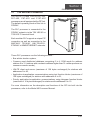
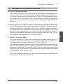
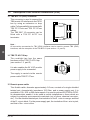
3.1-1 TSX and PMX Processors
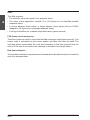
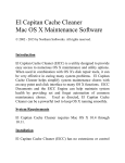
The TSX P47-415, TSX/PMX P47-455,
P67-455, P87-455 and P107-455 PLC
processors are all equipped with a FIP link.
PMX 47
B
455
RUN
!
The default operating mode of this link is
FIPWAY, meaning that the PLC must be
configured with XTEL-CONF in order for it
to be able to run in FIPIO mode.
CPU
MEM
I/O
FIP
For more information on this configuration,
refer to section 5, part D.
The PLC processor is connected to the FIPIO bus via the TSX LES 65 or TSX LES 75
terminal blocks.
When operating in FIPIO mode, these PLC processors support the following services :
• Bus arbiter election system,
• UNI-TE client and server (maximum of 128 bytes exchanged) for stations with
addresses 0 to 63,
• Application-to-application communication using text function blocks (maximum of 128
bytes exchanged) for stations with addresses 0 to 63.
For more information on the description and functions of the FIP link built into the
processors refer to the Model 40 Processor Manual.
___________________________________________________________________________
B3/1
___________________________________________________________________________
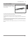
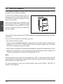
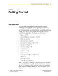
3.1-2 APRIL 5000 Processors
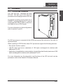
The CPU5030 and CPU5130 PLC
processors are all equipped with a FIPIO
link as standard.
B
The PLC processor is connected to the
FIPIO bus using the KIT5130 cord.
For more information on the description
and functions of the FIPIO link built into the
processors refer to the APRIL 5000 PLC
Manual Ref. TEM30000E.
___________________________________________________________________________
B3/2
3
Connectable Devices
____________________________________________________________________________
3.2
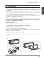
TBX Remote I/O
AEG Schneider Automation offers two types of TBX remote I/O interfaces :
• TBX monobloc low-cost modules made of one element. They comprise 16 inputs or
16 outputs.
• TBX discrete and dialog modular interface modules composed by the user by
associating one communication module and a connection base. This assembly can
be extended by adding a second connection base or extension module.
They are connected to the FIPIO fieldbus by a TBX BLP 01 SUB-D 9-point connector,
by means of an extension or drop cable.
• TBX sealtight (IP65) made of one element. They comprise 8 inputs or outputs.
They are connected to the FIPIO fieldbus by a TBX BLP 10 SUB-D 15-point connector,
by means of an extension or drop cable.
These remote I/O will :
• Reduce the cabling needed for the sensors and actuators,
• Do away with the mechanical stress inherent in cableways,
• Reduce connection design and test time,
• Provide more machine or installation availability,
• Provide open-ended installations that can be tailored to requirements through the
number and type of modules used,
• Allow a more rational operation of the PLCs,
For more information on these modules (characteristics, implementation etc.) refer to
the TBX Remote I/O Module Manual.
Monobloc TBX
Modular TBX
Sealtight TBX
___________________________________________________________________________
B3/3
B
___________________________________________________________________________
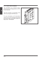
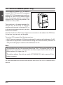
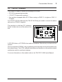
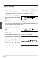
3.3
TSX FPC 10 Module
This module is used to connect the following to the FIPIO bus :
• FTX 507 programming terminals,
B
• CCX 57/77 supervision systems,
• Any machine equipped with a PC AT bus running on DOS 3.1 or higher or OS/2 ≥1.1
or higher.
The TSX FP CE 030 cable and the TSX FP ACC4 or TBX FP ACC10 tap are used to
connect the above devices to the FIPIO bus.
This module is a half-size PC extension
board. It slides into one of the slots on the
bus.
A FIP OS/2 driver, a FIP DOS driver and an Installation Manual are provided with this
module.
The programming terminal that includes the TSX FPC 10 interface module must be
connected to address 63 of the FIPIO bus to be able to access the complete architecture
without having to be configured first.
For more information on this module refer to the TSX FPC 10/20 User's Manual.
___________________________________________________________________________
B3/4
Connectable Devices
3
____________________________________________________________________________
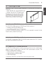
3.4
TSX FPC 20 Module
This module is used to connect the FTX
417-20 programming terminal running on
DOS 3.3 or higher or on OS/2 1.1 or higher
to the FIPIO bus.
B
The TSX FP CE 030 cable and the TSX FP ACC4 or TBX FP ACC10 tap are used to
connect the above devices to the FIPIO bus.
This module slides into the slot provided in the FTX 417-20 terminal.
A FIP OS/2 driver, a FIP DOS driver and an Installation Manual are provided with this
module.
The programming terminal that includes the TSX FPC 10 interface module must be
connected to address 63 of the FIPIO bus to be able to access the complete architecture
without having to be configured first.
For more information on this interface module refer to the TSX FPC 10/20 User's
Manual.
___________________________________________________________________________
B3/5
___________________________________________________________________________
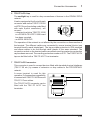
3.5
B
TSX FPG 10 Module (series 7 only)
This module in version V1.1 is used to
connect TSX 17-20 micro PLCs equipped
with the PL7-2 V5 language micro-software
cartridge. A TSX FP ACC2 SUB-D 9-point
male connector is used to connect this
module to the FIPIO bus by means of an
extension or drop cable.
This module is in the same standard format (52 mm) as the TSX 17 extension
modules and connects to the base PLC or
to the previous extension block by a cable
built into the module.
The TSX 17-20 micro-PLCs only support one connection to be made to the FIPIO bus.
On the bus, they can only act as agent.
The micro-PLCs support the following services :
• UNI-TE server (maximum of 32 bytes exchanged) for stations with addresses 0 to 62,
• Application-to-application communications using text function blocks (maximum of
32 bytes exchanged) for stations with addresses 0 to 62.
Note :
The simultaneous use of the services offered by a TSX 17-20 module (UNI-TE and
application-to-application communication services) implies that the module has a
station address no higher than 15.
The station address 0 must be a model 40 TSX/PMX PLC with a version 5.2 or
higher processor.
For more information on the use of this module, refer to the TSX FPG 10 Module User's
Manual.
___________________________________________________________________________
B3/6
Connectable Devices
3
____________________________________________________________________________
3.6
PCMCIA type III Cards
The PCMCIA type III cards are used as standard for connecting various devices to the
FIPIO bus :
• FIPIO TSX FPP 10 (*) agent PCMCIA card,
B
• FIPWAY TSX FPP 20 (*) PCMCIA card.
Depending on the devices, cables or DOS
and OS/2 drivers on diskette are used with
these cards. They are all connected to the
TSX FP ACC4 or TBX FP ACC10 taps.
3.6-1 Module for FTX 417-40 Notebook or PC-compatible
The TSX FPP K 200M module for PCMCIA type III slot consists of :
• 1 FIPWAY TSX FPP 20 PCMCIA card,
• 1 set of DOS and OS/2 driver 3"1/2 diskettes.
A TSX FP CG010/030 connection cable (1 or 3 m) is required to connect it to the
TSX FP ACC4 or TBX FP ACC10 tap.
3.6-2 Module for CCX 17 Operator Panel
The TSX FPP 10 card with a TSX FP CG010/030 cable connect the CCX 17 panel to
the TSX FP ACC4/TBX FP ACC10 tap.
3.6-3 Module for ATV 16 Variable Speed Drive
The TSX FPV 16 V5M module is used to connect asynchronous motor variable speed
drives via ATV 16 fitted with a VW3-A16 303 communication module. The
TSX FPV 16V5M module consists of :
• 1 FIPIO TSX FPP 10 agent PCMCIA card,
• 1 TSX FP CG010 connection cable,
• 1 TSX FP ACC4 tap.
(*) respectively TSX FPP 01 and TSX FPP 02 until the first quarter of 1995.
___________________________________________________________________________
B3/7
___________________________________________________________________________
3.7
B
Open Access of the FIPIO via a PCMCIA Card
AEG Schneider Automation offers a complete development system for rapid and
economical FIP connections for a wide range of products and ensures their correct
operation in a FIPIO environment. This development system comprises :
• A hardware base : a standard format PCMCIA card
• The FIP software built into this card,
• A system for integrating new FIP-compatible equipment into the X-TEL and MINI X-TEL
software workshops (V5 and higher),
• Technical assistance with product development and validation.
3.8
Open Access of the FIPIO via the Built-in FIP Component
AEG Schneider Automation offers FIP components for developing connection interface
modules for other manufacturers' products. This development requires expertise in the
integration of components and information systems. For this type of development,
consult our Regional Technical Center.
This type of development was created for :
• A SEPAM 200 (Merlin Gérin) distribution station control and monitoring system
• Concentrators for Endress + Hauser measurement sensors.
Endress + Hauser equipment can be connected to the FIPIO fieldbus via Commutec
transmitters and the ZA 674 communication interface (supplied by Endress + Hauser).
Integration into the X-TEL or MINI X-TEL software workshop is provided by the
TXT LF FP ZA 674 V52 software.
___________________________________________________________________________
B3/8
Services
Section 44
4 Services
____________________________________________________________________________
4.1
Remote I/O service
The FIPIO fieldbus supports the remote I/O service. This is the FIPIO dedicated service.
This service is used to exchange input status variables and output commands. Such
exchanges are performed cyclically and automatically without any intervention from the
application program.
Remote devices can be managed via this service (configuration etc.). These exchanges
are aperiodic without any intervention from the application program.
In order to use this service, the remote I/O must be configured with the correct software
workshop :
The XTEL-CONF station tool for series 7 (for more information on these configurations,
refer to the X-TEL Software Workshop Manual).
ORPHEE environment for series 1000 (for more information on these configurations,
refer to the ORPHEE Language and Software Manual).
The use of this service and the associated language interface are described :
For series 7 in the PL7-3 Languages, V5 Operating Modes Manual.
For series 1000 in the APRIL 5000 PLC Manual, Ref.TEM30000E.
The diagnostics and maintenance functions associated with this service are described :
For series 7 in the SYSDIAG, PL7-2/PL7-3 Application Adjustment Software Manual.
For series 1000 in the ORPHEE Language and Software Manual, Ref. TEM10000E, and
in the ORPHEE-DIAG Software Manual, Ref. TEM10800E. The SYSDIAG (DOS) tool
is used for diagnostic and maintenance purposes.
___________________________________________________________________________
B4/1
B
___________________________________________________________________________
4.2
B
UNI-TE Service
The FIPIO bus supports AEG Schneider Automation's UNI-TE industrial message
handling system protocol. UNI-TE enables point-to-point communication using a
question and answer dialog called Request/Confirm.
Dialog sequencing
A device that supports the UNI-TE protocol can be a :
CLIENT
: This device initiates communication. It asks a question (reads), sends a
command (writes) or an order (Run, Stop etc.).
SERVER
: This device executes the order sent by the client and sends a confirm after
execution.
The services supported depend on the type of device, e.g. PLC, programming terminal,
supervision system. Depending on its function, each device can be a Client and/or a
Server. A programming terminal is generally a Client on FIPIO and communicates with
the server of the bus arbiter PLC.
1
Request
Client
Server
2
Action
E
3
Confirm
UNI-TE is especially suited to applications such as supervision, diagnostics and control.
The maximum length of the messages is 128 characters.
Exchange integrity
The UNI-TE services uses a FIP message system data link level transmission and
acknowledgment exchange.
___________________________________________________________________________
B4/2
How to Connect a Section
Device
55
5 How to Connect a Device
____________________________________________________________________________
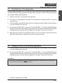
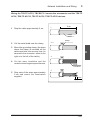
5.1
First Start-Up of the Application
This procedure applies to a FIPIO fieldbus which has been wired using the procedure
which ensures bus matching and continuity (refer to section 4, part D). It is used to detect
any multiple address declarations.
1 Switch off the PLC and all the FIPIO devices,
2 For series 7, code address 0 on the PLC terminal block, connect the PLC to the bus
and power up,
3 Code the address on the first device to be connected (read the label) and then power
it up and connect it to the bus,
4 Check that the DEF LED (*) goes out. If the RUN, DEF (*), I/O and COM LEDs flash
simultaneously after two seconds, then switch off the device and check the address
coding because a device with this address is already connected to the bus,
5 Repeat points 3 and 4 for each device which is to be connected. Leave the devices
that have already been connected continuously powered up.
5.2
Adding a Device to an Existing Application
1 Code the address on the first device to be connected (read the label) and then power
it up and connect it to the bus,
2 Check that the DEF LED (*) goes out. If the RUN, DEF(*), I/O and COM LEDs flash
simultaneously after two seconds, then switch off the device and check the address
coding because a device with this address is already connected to the bus.
Important
TBXs must be powered up after the address has been coded since the new address
is only taken into account after power up.
(*) ERR for sealtight TBX (IP65).
___________________________________________________________________________
B5/1
B
___________________________________________________________________________
B
___________________________________________________________________________
B5/2
A
FIPWAY Cell Network
Section
Contents
Page
1 Examples of FIPWAY Architectures
1/1
1.1
General
1/1
1.2
Examples
1.2-1 TSX 17 Single Network Architecture
1.2-2 Single Network Architecture
1.2-3 Multiple Network Architecture
1/2
1/2
1/3
1/4
2 Operating Principle
2/1
2.1
General
2/1
2.2
FIPWAY Exchange Format
2/3
3 Connectable Devices
3/1
3.1
TSX and PMX Processors
3/1
3.2
TSX FPG 10 Module
3/2
3.3
TSX FPC 10 Module
3/3
3.4
TSX FPC 20 Module
3/4
3.5
TSX FPP K 200M PCMCIA type III card
3/4
___________________________________________________________________________
C/1
C
FIPWAY Cell Network
Section
Contents
Page
4 Services
4/1
4.1
COM Service
4/1
4.2
UNI-TE Service
4/2
4.3
Application-to-Application Communication
4/3
4.4
Priority Communication : Telegram
4/4
C
5 Characteristics and Performance
5/1
5.1
Characteristics
5/1
5.2
Performance
5/3
6 How to Connect a Device
6/1
6.1
First Start-Up of the Application
6/1
6.2
Adding a Device to an Existing Application
6/1
___________________________________________________________________________
C/2
Section 1
1 Examples of FIPWAY Architectures
____________________________________________________________________________
1.1
General
Note :
In this document, the term segment means the part of the network between two repeaters or
bridges, the term network means all the segments with the same network address and the term
multiple network means an architecture comprising several interconnected networks.
The FIPWAY cell network is used mainly for level 1 applications such as coordinating
all TSX and MPX PLCs, control and supervision systems and workshop terminals;
FIPWAY can be used in setting up distributed automation control systems even if they
are composed solely of TSX 17 micro-PLCs.
These applications are carried out by the set of devices that can be connected to the
FIPWAY network :
• TSX 7 modular PLCs and PMX 7 model 40 PLCs,
• TSX 17 micro-PLCs,
• FTX 507 programming terminal,
• FTX 417 programming terminal,
• CCX 57/77 supervision and control system,
• PC-compatible terminal.
FIPWAY runs immediately without requiring configuration and supports all the
communications services required by automation personnel with guaranteed refresh
time, of the distributed database, network transparency and the UNI-TE message
system services.
The FIPWAY cell network can be used in several ways :
• In a simple environment (single network) with one segment,
• In a hierarchical environment (multiple network) where several segments can be
connected in the workshop by a higher level local network such as MAPWAY,
ETHWAY or MMS / ETHERNET.
The various architecture possibilities are shown on the following pages.
___________________________________________________________________________
C1/1
C
___________________________________________________________________________
1.2
Examples
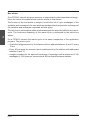
1.2-1 TSX 17 Single Network Architecture
Pumping System Automation Control System
C
CCX 77
FIPWAY
TSX 17
TSX 17
TSX 17
TSX 17
TSX 17
TSX 17
TSX 17
FIPWAY
TSX 17
FIPWAY is designed for the low-cost automation of a geographically spread out site. The
maximum permissible length is 5000 meters with the use of repeaters. All the TSX 17s
in this type of architecture are part of the same network.
The type of cable used (twisted pair) and the exclusive use of TSX 17 micro-PLCs make
this a particularly economical solution.
___________________________________________________________________________
C1/2
Examples of FIPWAY Architectures
1
____________________________________________________________________________
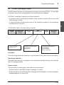
1.2-2 Single Network Architecture
Finished Product Packing Cell
Workshop
terminal
FIPWAY
Control system,
shipping check
FTX 417
CCX 77
C
TSX 17
TSX 47
Conveyor feed
control
TSX 17
TSX 17
Palletizing,
storage
TSX 17
TSX 17
TSX 17
TSX 17
Banding cell
TSX 17
Packing cell
FIPWAY ensures the synchronization functions related to the handling of finished
products at a reduced cost.
It enables simple machines such as banding machines or packing machines controlled
by TSX 17 micro-PLCs to be connected.
The cell is controlled by a supervision system that is connected directly to the network.
Information concerning shipping, statistics etc. are periodically sent to the control
system.
___________________________________________________________________________
C1/3
___________________________________________________________________________
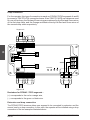
1.2-3 Multiple Network Architecture
Production plant
Programming
terminal
CAPM
station
FTX 507
ETHWAY
CCX 77
C
Bridge
PLC
Bridge
PLC
FIPWAY
FIPWAY
TSX 17
Production cell
TSX 17
TSX 17
TSX 17
Packing cell
In this type of hierarchical architecture, several FIPWAY cell networks are connected by
the plant-wide ETHWAY network.
The transparency provided by this type of architecture carries production and distribution data to the Computed-aided Production Management (CAPM).
Similarly, all the functions of the X-TEL software workshop are supported by the stations
connected to FIPWAY by means of ETHWAY / FIPWAY bridge PLCs.
___________________________________________________________________________
C1/4
Operating Principle
Section 22
2 Operating Principle
____________________________________________________________________________
2.1
General
A device connected to FIPWAY is identified by a unique address formed by the network
number and the station number.
Network number
The network number takes the following values :
• 0 in single network layers,
• 1 to 127 in multiple network layers or in single network layers that may be connected
later on.
Station number
The station number represents the physical address of the device on the network and
takes a value between 0 and 63.
The network address/station address of a device connected to FIPWAY will build link
layer addresses :
• To enable the device to address produced variables (broadcast),
• For addressing variables sent by the device or sent to the device.
Variable link addressing is performed via an identifier coded on a 16-bit integer. The
application variables sent are common words (COM) which use the variable cyclic
transfer link service.
Each link message sent contains the address of the source entity and the address of the
target entity. Each address is coded on 24 bits.
FIPWAY offers two types of application messages :
• Telegrams which use the acknowledged messages cyclic transfer link service,
(telegrams are always equivalent to point-to-point communication),
• Datagrams which use the aperiodic message transfer service. These messages are :
- acknowledged if messages are sent in point-to-point mode,
- not acknowledged if messages are sent in broadcast mode.
___________________________________________________________________________
C2/1
C
___________________________________________________________________________
Bus arbiter
On a FIPWAY network at a given moment, a unique station authorizes data exchange :
this is the active bus arbiter which controls access to that device.
The function of the bus arbiter is simple. It scrolls the list of cyclic exchanges of the
variables and messages to be sent and then decides when the aperiodic exchanges of
the variables and messages requested will take place.
The list of cyclic exchanges and the windows assigned for aperiodic traffic form a macrocycle. The continuous scanning of this macro-cycle is performed by the active bus
arbiter.
C
On a FIPWAY network the macro-cycle is the same irrespective of the application
program. The macro-cycle :
• Scans the telegrams sent by the stations with an address between 0 and 15 every
10 ms,
• Every 40 ms scans the common word variables sent by the stations with addresses
between 0 and 31,
• Assigns a window for the aperiodic exchange of messages with a maximum of 210
messages of 128 bytes per second which will be shared between stations.
___________________________________________________________________________
C2/2
Operating Principle
2
____________________________________________________________________________
2.2
FIPWAY Exchange Format
The following information is not absolutely necessary when using FIPWAY. It is provided
for familiar users as a brief explanation of how the network operates.
A FIPWAY exchange comprises two frame transfers :
• A question frame containing the identifier of the variable to send or the source entity
of a message to send,
• A response frame containing the value of the identified variable or the application
message sent on the bus.
C
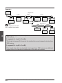
The FIPWAY frame is broken down as follows :
Preamble
8 bits
Start Frame
Delimiter
Frame control
1 byte
Data
0 to 262 bytes
6 bits
If question frame :
identifier value
FCS
2 bytes
End Frame
Delimiter
7 bits
if variable response frame :
I/O, presence,
variables etc
If message response frame :
target address
source address
series 7 datagram
Preamble :
This 8-bit string allows the receivers to synchronize to the clock of the source station.
Start frame delimiter :
This start frame delimiter comprises six bits and allows the date link layer to locate the
start of its assigned data.
Frame control :
This byte tells you what type of frame has been exchanged :
• Question frame : identified variable, message or request,
• Response frame : identified variable, message acknowledged or not acknowledged,
acknowledgment or request etc.
___________________________________________________________________________
C2/3
___________________________________________________________________________
Data :
This field contains :
• The identifier value (two bytes) for a question frame,
• The value of the application variable (2 to 128 bytes) for an identified variable
response frame,
• A source address (three bytes), a target address (three bytes) and a series 7 datagram
(128 bytes) for a message response frame,
• A string of identifiers for a request response frame (system service).
C
FCS (frame check sequence) :
These two bytes are used to check that the data exchange is performed correctly. The
control code is calculated by the source station and sent after the data. The receiving
station recalculates the code and compares it with that received from the source. If the
two do not match the message is refused by the target station.
End frame delimiter :
The end frame delimiter comprises seven bits and allows the data link layer to locate the
end of its assigned data.
___________________________________________________________________________
C2/4
Connectable Devices
Section 33
3 Connectable Devices
____________________________________________________________________________
3.1
TSX and PMX Processors
The TSX P47-415 and TSX/PMX P47-455,
P67-455, P87-455 and P107-455
processors are all equipped with a FIP link.
The default operating mode of this link is
FIPWAY.
PMX 47
455
RUN
!
CPU
The PLC processor is connected to the
FIPWAY network via the TSX LES 65 or
TSX LES 75 terminal block.
MEM
I/O
FIP
Each modular PLC supports a unique FIP
connection as well as connection to the
MAPWAY, TELWAY, UNI-TELWAY,
ETHWAY or MMS/ETHERNET networks.
C
These PLC processors run the following services :
• Bus arbiter election system,
• Common word distributed database comprising 0 to 4 COM words for address
stations 0 to 31 (stations with a network address higher than 31 neither produce nor
consume common words),
• UNI-TE client and server (maximum of 128 bytes exchanged) for stations with
addresses 0 to 63,
• Application-to-application communications using text function blocks (maximum of
128 bytes exchanged) for stations with addresses 0 to 63,
• Priority application-to-application communications using telegram function blocks
(maximum of 16 bytes exchanged) for stations with addresses 0 to 15.
For more information on the description and functions of the FIP link built into the
processors, refer to the Model 40 Processor Manual.
___________________________________________________________________________
C3/1
H
___________________________________________________________________________
3.2
TSX FPG 10 Module
This module is used to connect TSX 17-20 micro-PLCs equipped with the PL7-2 V5
language micro-software cartridge.
A TSX FP ACC SUB-D 9-point male connector is used to connect this module to
the FIPWAY network by means of an extension or drop line.
C
This module is the same standard format
(52 mm) as the TSX 17 extension modules
and connects to the base PLC or to the
previous extension block by a cable built
into the module.
The micro-PLCs only support one FIPWAY network connection as well as a UNI-TELWAY
connection.
The micro-PLCs support the following services :
• Bus arbiter election system,
E
• Common word distributed database comprising O to 4 COM words for stations with
addresses 0 to 15 (TSX 17 stations with a network address higher than 15 neither
produce nor consume common words),
• UNI-TE server (maximum of 32 bytes exchanged) for stations with addresses 0 to 62,
• Application-to-application communications using text function blocks (maximum of
32 bytes exchanged) for stations with addresses 0 to 62.
Note :
The simultaneous use of the services offered by a TSX 17-20 module (COM, UNI-TE
and application-to-application communication services) implies that the module has a
station address no higher than 15.
For more information on the use of this module, refer to the FIPWAY TSX FPG 10
Module User's Manual.
___________________________________________________________________________
C3/2
Connectable Devices
3
____________________________________________________________________________
3.3
TSX FPC 10 Module
This module is used to connect the following to FIPWAY :
• FTX 507 programming terminals,
• CCX 57/77 supervision systems,
• Any machine equipped with a PC AT bus running on DOS 3.1 or higher or OS/2 1.1
or higher.
The TSX FP CE 030 cable and the TSX FP ACC4 tap are used to connect the above
devices to a FIPWAY segment.
This module is a half-size PC extension
board. It slides into one of the slots on the
bus.
C
A FIP OS/2 driver, a FIP DOS driver and an Installation Manual are provided with this
module.
Once connected to FIPWAY, the programming terminals can access all the stations on
the network layer. The X-TEL software workshop can therefore run the whole network
architecture and its constituent stations.
For more information on this module refer to the TSX FPC 10/20 User's Manual.
___________________________________________________________________________
C3/3
H
___________________________________________________________________________
3.4
TSX FPC 20 Module
This module is used to connect the FTX
417 programming terminal running on DOS
3.3 or higher or OS/2 1.1 or higher.
The TSX FP CE 030 cable and the TSX FP
ACC4 tap are used to connect the above
devices to a FIPWAY segment.
C
This module comprises an element (case
and board) which slides into the slot
provided in the FTX 417 terminal.
A FIP OS/2 driver, a FIP DOS driver and an
Installation Manual are provided with this
module.
Once connected to FIPWAY, the programming terminals can access all the stations on
the network layer. The whole network architecture and its constituent stations can then
be used.
For more information on this module refer to the TSX FPC 10/20 User's Manual.
E
3.5
TSX FPP K 200M PCMCIA type III card
The module is used to connect the
FTX 417-40 notebook to the FIPWAY
network under DOS or OS/2.
It consists of :
• 1 FIPWAY PCMCIA TSX FPP 20
PCMCIA card,
• 1 set of DOS and OS/2 driver 3"1/2
diskettes.
A TSX FP CG 010/030 connection cable (1
or 3 m long) is used for connection to the
TSX FP ACC4 tap.
Using a FIPWAY connection, the FTX 417-40 notebook can access all stations in an
X-WAY architecture. It is also possible to perform the complete setup of the network and
the stations which are connected to it.
The TSX FPP K 200M module is used for connecting a PC-compatible which has a
PCMCIA type III slot.
___________________________________________________________________________
C3/4
Services
Section 44
4 Services
____________________________________________________________________________
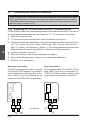
4.1
COM Service
FIPWAY supports the TSX series 7 COM (common) word service. The complete set of
COM words forms a database that is distributed among some or all of the devices
connected to the same segment of the network :
• The database comprises 256 words of 16 bits (four words per station),
• Only stations with addresses 0 to 31 (0 to 15 TSX 17-20 PLCs) handle common words,
Principle of operation
The common words are exchanged automatically in cyclic mode without intervention
from the application program. The complete database on a network is updated every
40 ms.
Use of the distributed COM word database is recommended for the periodical sending
of status variables without adding extra application program workload. To send data on
brief events, application-to-application communication with a confirm is recommended
as transmission is guaranteed.
C
FIPWAY
TSX 17
Station 0
TSX 17
Station 1
TSX 7
Station 31 max.
Write :
to COM field
in the station
Read :
available to all
connected stations
Common memory field
(128 16-bit words)
The PLCs using the COM word service must enable their COM word activity when being
configured. For more information on configuration refer to the PL7-3, V5 Operating
Modes Manual for model 40 PLCs and to PL7-3 V5/X-TEL Operating Modes Manual for
TSX 17-20 PLCs.
___________________________________________________________________________
C4/1
H
___________________________________________________________________________
4.2
UNI-TE Service
The FIPWAY network supports AEG Schneider Automation's UNI-TE industrial message
system protocol. UNI-TE enables point-to-point communications using a question and
answer dialog called Request/Confirm.
Dialog sequencing
A device that supports the UNI-TE protocol can be a :
C
CLIENT
: This device initiates communication. It asks a question (reads), sends a
command (writes) or an order (Run, Stop etc.).
SERVER
: This device executes the order sent by the client and sends a confirm after
execution.
The services supported depend on the type of device, e.g. PLC, programming terminal,
supervision system. Depending on its function, each device can be a Client and/or a
Server. TSX 17-20 PLCs are only servers on UNI-TE.
The maximum size of the messages is 128 characters (32 characters for TSX 17-20
automates).
1
Request
\
Server
Client
2
Action
3 Confirm
UNI-TE is especially suited to applications such as supervision, diagnostics and control.
Exchange integrity
The UNI-TE service uses a FIP message system data link level transmission and
acknowledgment exchange.
___________________________________________________________________________
C4/2
Services
4
____________________________________________________________________________
4.3
Application-to-Application Communication
FIPWAY also supports communication between applications in point-to-point mode by
TXT block. This service is the same as the UNI-TE Unsolicited Data service and does
not provide a confirm.
This service is especially suited to :
• Sending alarm messages from a PLC to a supervision system,
• Exchanging data tables between two PLCs under the control of the application
programs in the source and target device,
The maximum size of application-to-application messages is restricted to 128 characters
(32 characters for PSX 17-20 PLCs) for both reading and writing.
C
FIPWAY
TSX 17
Station 0
TSX 17
Station 1
TSX 7
Station 63 max.
Table of internal words Wi
or constants CWi
___________________________________________________________________________
C4/3
H
___________________________________________________________________________
4.4
Priority Communication : Telegram
The telegram service is a special type of application-to-application message designed
to transmit occasional urgent and high priority data between two PLCs on the same
network segment.
A telegram from the PLC processor to its network module is processed immediately
without waiting for the end of the PLC cycle.
It can be received by :
• Scanning the fast task,
C
• Sending an interrupt (as soon as the message reaches the target network module)
and processing in the interrupt task.
The maximum size of messages sent using this service is restricted to 16 bytes.
IT Task Read TLG
E
T
TSX 7
\
S
TSX 7
IT Task Fast or Mast
write TLG
Note
Only TSX and PMX 47-455, 67-455, 87-455 and 107-455 PLCs support the
telegram service. It is restricted to stations with addresses 0 to 15.
___________________________________________________________________________
C4/4
Characteristics and Performance
Section 55
5 Characteristics and Performance
____________________________________________________________________________
5.1
Characteristics
Structure
Type
: FIP-standard open industrial network.
Topology
: Devices connection in extension or drop mode.
Access Method
: Controlled by a bus arbiter.
Dedicated
exchanges
: Telegrams, common words and UNI-TE messages.
Transmission
Mode
: Base band physical layer on shielded twisted pair (French standard
NF C46 604).
Binary data-rate
: 1 Mb/s.
Medium
: Shielded twisted pair (impedance 150 Ohms).
C
Configuration
Nbr of stations
: 32 stations per segment (maximum of 64 for all segments).
Nbr of segments : A maximum of 5 (cascaded) using electrical or optical repeaters.
(maximum of 4 cascaded).
Length
: The length of a segment depends on the type of its drop connections.
Maximum permissible length is 1000 meters without a repeater for
a segment and 5000 meters between end devices (5 segments).
Multiple network : 127 FIPWAY, MAPWAY, TELWAY, ETHWAY, or MMS/ETHERNET
connected together.
Drops
: These connections are made through the use of taps, drop cables
or loop-back of the trunk cable. If a drop cable is used, the length
of the drop is equal to three equivalent trunk cable lengths. The
length of a segment is therefore equal to :
L = sum of Lpx + 3 x sum of Ldx ≤ 1000 m
Lp1
Ld1
Lp2
Lp3
Ld2
Lp4
Lp6
Lp5
Ld3
Lp : trunk cable
Ld : drop cable
___________________________________________________________________________
C5/1
H
___________________________________________________________________________
Services
COM
: Distributed database of a maximum of 128 words (4 words per
station). It comprises :
• Model 40 PLCs using 0 to 4 common words for stations with
addresses 0 to 31,
• TSX 17-20 micro-PLCs using 0 or 4 common words for stations
with addresses 0 to 15.
UNI-TE
: Point-to-point request service with confirm, 128 bytes maximum
and can be used by all the stations.
• The maximum size of messages is 128 bytes for model 40 PLCs,
• The maximum size of messages is 32 bytes for TSX 17-20
micro-PLCs.
Application-toapplication
: Point-to-point message service of a maximum of 128 bytes that can
be used by all the stations.
• The maximum size of these messages is 128 bytes for model 40
PLCs,
• The maximum size of these messages is 32 bytes for TSX 17-20
micro-PLCs.
Telegram
: Point-to-point priority message system (maximum of 16 bytes).
Only model 45 PLCs support this service. Access is restricted to
stations with addresses 0 to 15.
Data integrity
: Control characters on each frame with acknowledgment of
point-to-point messages using French standard NF C46 603.
Supervision
: Network status accessible via FTX 507, CCX 57, CCX 77, FTX 417
or PC-compatible terminals running NETDIAG software.
C
E
Maximum size of information sent
Variables
: 128 bytes.
Messages
: 128 bytes.
Message data-rate: 210 128-byte messages per second.
___________________________________________________________________________
C5/2
Characteristics and Performance
5
____________________________________________________________________________
5.2
Performance
FIPWAY ensures guaranteed and constant cycle time for a given configuration,
irrespective of the amount of traffic and the number of stations (2 to 64). A FIPWAY
installation can evolve (stations added or deleted) without compromising performance.
Maximum transmission time
• Telegrams (TLG)
Priority application messages are sent in less than 10 ms (1 TLG per station).
• Common words (COM)
The complete common word database is updated every 40 ms.
• UNI-TE message system (TXT)
UNI-TE or standard application-to-application messages are generally sent in less
than 80 ms (40 ms for stations with a network address lower than 32). If considerable
traffic is circulation on the network, some messages can wait several cycles before
being sent. The network can send a maximum of 210 128-byte messages per second.
C
These network characteristics mean that the application response time depends
exclusively on the processing capacity of the connected devices. A 50 Kword program
can be downloaded in less than two minutes on a network with a normal workload.
Confirm
Event
TC1 TC1
TC1 TC1
TC1 = Device 1 cycle time
TCR
TCR
TCR = FIPWAY network cycle time
TC2 TC2
TC2 = Device 2 cycle time
Action
Response time must be assessed by application designers taking into account the
connected devices.
The processing time of a device may be one or two cycle times depending on the
asynchronous mechanisms used.
___________________________________________________________________________
C5/3
H
___________________________________________________________________________
C
E
___________________________________________________________________________
C5/4
Hoe to Connect a Section
Device
66
6 How to Connect a Device
____________________________________________________________________________
6.1
First Start-Up of the Application
This procedure applies to a FIPWAY network which has been wired using the procedure
guaranteeing bus matching and continuity (refer to section 4, part D).
1
Switch off all the FIPWAY devices,
2
Code the address of a device and then connect it to the network and power it up,
3
Code the address on the next device and then connect it to the network and power
it up,
4
Check that the DEF LED goes out. If the RUN LED flashes continuously, switch off
the device and check the address coding because a device with this address is
already connected to the bus,
5
6.2
Repeat points 3 and 4 for each device which is to be connected. Leave the devices
that have already been connected continuously powered up.
Adding a Device to an Existing Application
1
Code the address on the device to be connected and then connect it to the network
and power it up,
2
Check that the DEF LED goes out. If this LEDs flashes continuously, switch off the
device and check the address coding because a device with this address is already
connected to the bus.
___________________________________________________________________________
C6/1
C
___________________________________________________________________________
C
___________________________________________________________________________
C6/2
Connection Accessories
Section
Contents
Page
1 Connection Accessories
1/1
1.1
FIPWAY Network Connection Accessories
1/1
1.2
FIPIO Bus Connection Accessories (IP20)
1/2
1.3
Description of the Different Accessories
1/3
1.4
FIPIO Bus Connection Accessories (IP65)
1/9
1.5
Description of the Different Accessories (IP65)
D
2 Network Design
2.1
Principles
2.1-1 Determining the Number of Electrical Segments
2.1-2 Maximum Number of Devices
2.1-3 Line Terminators
3 Network Installation and Wiring
1/10
2/1
2/1
2/1
2/3
2/3
3/1
3.1
Installing the Cables
3.1-1 Cable usage criteria
3.1-2 Special case of sealtight TBXs
3.1-3 Installation rules
3/1
3/1
3/2
3/2
3.2
Installing Connection Accessories
3.2-1 Fastening
3.2-2 Grounding
3/2
3/2
3/3
3.3
Wiring the Bus
3/5
3.4
Preparing the cables
3/6
___________________________________________________________________________
D/1
Connection Accessories
Section
3.5
D
Contents
Connecting the Different Accessories
3.5-1 Connecting TSX LES 65 & TSX LES 75 Connection Boxes
3.5-2 Connecting TSX FP ACC2 Connectors
3.5-3 Connecting the TSX FP ACC4 Taps
3.5-4 Connecting the TBX FP ACC10 Taps
3.5-5 Connecting the TSX FP ACC6 Repeater
3.5-6 Connecting the TSX FP ACC8 Repeater
3.5-7 Connecting TBX BLP 01 Connectors
3.5-8 Connecting TBX BLP 10 Connectors
4 Checking the Network
Page
3/8
3/8
3/9
3/10
3/13
3/18
3/21
3/23
3/24
4/1
4.1
General
4/1
4.2
Checking Bus Continuity
4/2
4.3
Testing for Line Terminators
4/4
5 Series 7 Software Utilities
5/1
5.1
XTEL-CONF Station Tool
5/1
5.2
SYSDIAG Station Tool
5/2
5.3
NETDIAG Software
5/3
5.4
PL7-NET Software
5/4
6 Series 1000 Software Utilities
6/1
6.1
ORPHEE Configuration
6/1
6.2
ORPHEE or ORPHEE-DIAG Diagnostics
6/2
6.3 SYSDIAG Station Tool (DOS)
6/3
___________________________________________________________________________
D/2
Connection Accessories
Section 11
1 Connection Accessories
____________________________________________________________________________
1.1
FIPWAY Network Connection Accessories
AEG Schneider Automation offers a range of accessories for connecting the various
devices to the FIPWAY networks.
8
2
3
8
CCX 57
TSX 7
3
TSX 7
2
I/O Extension
6
6
1
FTX 507
1
1
7
5
D
9
TSX 17-20
5
1
7
7
FTX 417
TSX 17-20
TSX 17-20
6
E
3
7
7
6
5
TSX 17-20
TSX 17-20
5
1
TSX FP CA/CRxxx : Trunk cable,
2
TSX FP CCxxx
: Drop cable,
3
TSX FP CE030
: Connector cable for terminals and PC,
5
TSX FP ACC7
: Line terminator,
6
TSX FP ACC4
: Tap,
7
TSX FP ACC2
: Extension or drop cable connector,
8
TSX LES 65/75
: Terminal block for modular PLC,
9
TSX FP ACC6
: Electrical repeater,
TSX FP ACC9
: Tool for testing the wiring system.
___________________________________________________________________________
D1/1
H
___________________________________________________________________________
1.2
FIPIO Bus Connection Accessories (IP20)
AEG Schneider Automation offers a range of accessories (IP20) for connecting the
various devices to the FIPIO bus. These are the same as those used for FIPWAY. Only
the TBX BLP 01 connector is a FIPIO dedicated connector.
APRIL® 5000
FTX 507
(series 7 only)
11
8
5
2
TSX 7
TBX
3
5
D
TBX
6 or 12
2
9
5
1
7
3
TBX
11
TBX
TBX
11
TBX
CCX 57
(series 7 only)
1
Cabinet
5
TBX
1 TSX FP CA/CRxxx : Trunk cable (1a or 1b),
2 TSX FP CCxxx
: Drop cable,
3 TSX FP CE030
: Connector cable for terminals and PC (3a),
or KIT5130
: APRIL 5000 cord (3b),
5 TSX FP ACC7
: Line terminator,
6 TSX FP ACC4
: Tap,
7 TSX FP ACC2
: Extension or drop cable connector,
8 TSX LES 65/75
: Terminal block for modular PLC,
9 TSX FP ACC6
: Electrical repeater,
11 TBX BLP 01
: TBX connector,
14 TBX FP ACC10
: Tap,
TSX FP ACC9
: Tool for testing the wiring system.
___________________________________________________________________________
D1/2
Connection Accessories
1
____________________________________________________________________________
1.3
Description of the Different Accessories
1a TSX FP CA xxx trunk cable
This 8-mm diameter 150 Ohm cable comprises a shielded single twisted pair. It is
available in 100-, 200- or 500-meter spools with outer insulation made of black PVC.
It is used to connect the various devices to the FIPWAY/FIPIO network either directly
or by using TSX FP ACC4 taps. The D+ wire insulation is red and D- insulation is
green. The characteristics of the trunk cable are provided in the Appendix, part E,
section 1.4.1.
1b TSX FP CR xxx trunk cable for harsh environments for sealtight TBX modules
This 150 Ohm flexible cable, approximately 9.3 mm in diameter, comprises a single
shielded twisted pair. It is available in 100-, 200- or 500-meter spools. It is used to
connect devices to the FIPWAY/FIPIO network either directly or using TSX FP ACC4
taps. Its characteristics enable it to be used in mobile installations or subject to
particular environmental constraints (out of doors, chemical corrosion, etc.). The D+
wire insulation is orange and the D- insulation is black.
2
D
TSX FP CC xxx drop cable
This 8-mm diameter 150 Ohm cable comprises two shielded twisted pairs. It is
available in 100-, 200- or 500-meter spools with outer insulation made of black PVC.
It is used for drop connections made from a TSX FP ACC4 tap.
The trunk cable length to take into account for network calculations is three times the
physical length of the drop cable. The "electric" length of a drop connection is three
times its physical length. The insulation of the D+ wires is red and orange and that
of the D- wires is green and black. The characteristics of the drop cable are provided
in the Appendix, part E, section 1.4.3.
E
TSX FP CR trunk cable, diameter 8.5 mm, is a shielded twisted pair. Its characteristics
are identical to those of the TSX FP CF.
___________________________________________________________________________
D1/3
H
___________________________________________________________________________
3a TSX FP CE 030 cord
This cord comprises 3-meter long shielded multiple pair cable with a connector fitted
to each end : a 15-point connector for connection to the terminal and a 9-point
connector for connection to the network. It is used to connect FTX 507, FTX 417,
CCX 7 and PC-compatible terminals to the FIPWAY/FIPIO network. The terminal
must be fitted with a TSX FPC 10 network interface module (for FTX 507, CCX 7 or
PCs equipped with an ISA bus) or a TSX FPC 20 module (for FTX 417).
A TSX FP ACC4 or TBX FP ACC10
tap must be used for connection to the
bus.
TSX FP CE 030
3b KIT5130 cord
This cord is electrically identical to the TSX FP CE 030 cord above, and only differs
in the shape of the 9-point connector. It is right-angled, making it possible to close
the door of the APRIL 5000 processor module.
D
A TSX FP ACC4 or TBX FP ACC10
tap must be used for connection to the
bus.
5
KIT5130
TSX FP ACC7 line terminator
This line terminator is used for matching FIPWAY/FIPIO segments.
A line terminator must therefore be
placed at both ends of each bus
segment. It is unpolarized and can be
connected to all TSX LES 65 or 75,
TSX
FP
ACC2/ACC4/ACC6,
TBX BLP 01
or
TBX BLP 10
connection accessories in place of the
second segment of the trunk cable.
___________________________________________________________________________
D1/4
Connection Accessories
1
____________________________________________________________________________
6
TSX FP ACC4 tap
• • ••
•••
••••• •
It is also equipped with a 9-point female
connector and via the TSX FP CE 030
or KIT5130 cord (excluding cords fitted
with male 9-point connectors), will
connect :
- a terminal in which a TSX FPC 10/20
or a PCMCIA TSX FPP 10/20 board
has been mounted,
- an APRIL 5000 PLC.
••
The sealtight tap is used for drop connections of devices to the FIPWAY/FIPIO
network.
•••• • • • •
The operation of the network is not affected by the connection or disconnection of
the terminal. The different cables are connected by screw terminal blocks (one
terminal block for each twisted pair). The tap provides protection to IP54 standard
and allows cables to be fed through cable glands of the same standard. The
connection socket on the terminal can be accessed once the quarter-turn protection
cap has been removed. The resulting protection number is IP 21. The TSX FP ACC4
tap can be fitted with a TSX FP ACC7 line terminator.
7
D
TSX FP ACC2 connector
This connector is used to connect devices fitted with standard physical interfaces
(TSX 17-20 etc.) by means of extension or drop cables to the FIPIO/FIPWAY
network.
E
A screw terminal is used for this
operation. Full connection compatibility
is ensured with TSX FP CA/CRxxx and
TSX FP CCxxx cables.
The TSX FP ACC2 connector can be
fitted with the TSX FP ACC7 line
terminator.
___________________________________________________________________________
D1/5
H
___________________________________________________________________________
8
TSX LES 65 or 75 connection box
This box which is connected to the front of series 7
processors is equipped with a FIP port and is used to
connect the PLC to the FIPWAY/FIPIO network.
The TSX LES 65 and TSX FP 75 connection boxes
can be fitted with the TSX FP ACC7 line terminator if
the configuration of the PLC at the end of the segment
does not have a remote or local extension. If these
extensions are installed, the TSX FP ACC7 line
terminator must be mounted in the TSX FP ACC4 tap.
In the case of local or remote extensions via optical fibers, the base rack must be
connected using a drop connection.
Depending on the type of extension used, the choice of a TSX LES 65 or 75 tap is
as follows :
Local extension
D
TSX LES 65
Optical or electrical remote
extension (example of optical fiber)
TSX LES 75
FIPWAY/FIPIO
FIPWAY/FIPIO
This connection box is equipped with two sets of micro-switches which are used to
code the network address (NET) and the station address (STA). See the next page.
Important note :
Each micro-switch is assigned a binary order. Micro-switch 8 is assigned binary
order 1, micro-switch 7 binary order 2, etc. and micro-switch 1 is assigned binary
order 128.
A micro-switch set to ON corresponds to binary order 0.
If a PLC is configured for connection to FIPIO, it must have a unique address on
the bus. This address must be 0. To do this, all the STA and NET micro-switches
must be set to ON.
___________________________________________________________________________
D1/6
1
Connection Accessories
____________________________________________________________________________
FIPIO example
Network 10 and Station 15 example
SW1
ON
ON
SW2
1 2 3 4 5 6 7 8
STA
1 2 3 4 5 6 7 8
NET
1 2 3 4 5 6 7 8
ON
ON
SW2
9
STA
1 2 3 4 5 6 7 8
NET
SW1
TSX FP ACC6 electrical repeater
This sealtight module is used to connect
two FIPWAY/FIPIO segments, thus
increasing the length of the network.
Linear or tree-type topologies are
obtained in this way and the number of
devices able to be connected to the
network is also increased (a maximum
of 64 logical connections on the
complete network). By using several
repeaters, the maximum network length
is 5000 meters.
D
Screw terminals are used to connect the various cables. This module uses 24 V DC
(150 mA) or 48 V DC (75 mA) which is connected to a special terminal block. Four
LEDs indicate that this terminal block is operating correctly. The TSX FP ACC6
repeater provides protection to IP65 standard and allows cables to be fed through
cable glands of the same standard. It can be fitted with TSX FP ACC7 line
terminators.
E
10 TSX FP ACC8 optical / electrical repeater
This sealtight module is used to connect
electrical cells (FIPWAY/FIPIO
segments), whose earth cannot be
made equipotential, and which are
further than 1000 m / 3000 m maximum
apart and/or separated by areas with
high levels of interference.
By using optical /electrical repeaters,
as with electrical repeaters, the number
of devices on FIPWAY/FIPIO can be
increased (64 logical connections max.)
as well as the length (5000 m max.).
___________________________________________________________________________
D1/7
H
___________________________________________________________________________
The optical / electrical repeater uses a 24 V DC or 48 V DC supply. Four LEDs
indicate that this terminal block is operating correctly.
A 2 m long optical cable (optical jumper) TSX FP JF 020 enables :
• the TSX FP ACC8 to be used as an interface between a FIP optical station and
a FIPWAY/FIPIO segment,
• the TSX FP ACC8 to be connected to an optical cable mixer enclosure.
Characteristics and performance : see Appendix 4, part E.
11 TBX BLP 01 connector
D
This connector is used to connect the
TBX remote I/O interfaces to the FIPIO
bus using an extension or drop cable.
Full compatibility is ensured with TSX
FP CA/CRxxx and TSX FP CCxxx
cables.
The TBX BLP 01 connector can be
fitted with a TSX FP ACC7 line
terminator.
12 FIP TSX FP ACC9 wiring test tool
This tool is used to test each segment
in the network (network continuity, line
terminators mounted, etc.). It comprises
two modules, Z and TP.
Z
GND
D—
D +
TP
___________________________________________________________________________
D1/8
1
Connection Accessories
____________________________________________________________________________
1.4
FIPIO Bus Connection Accessories (IP65)
AEG Schneider Automation offers a range of sealtight accessories (IP65) for connecting
the various devices to the FIPIO bus.
TSX 7
FTX 507
(series 7 only)
11
Power.
APRIL® 5000
4
6 or 12
5
2
TBX (IP65)
3
1
5
6 or 12
2
TBX (IP20)
9
5
1
7
3
D
Power
TBX (IP65)
TBX (IP20)
13
12
TBX (IP65)
CCX 57
(series 7 only)
1
TBX (IP20)
5
Cabinet
11
1
TSX FP CA/CRxxx : Trunk cable, (1a or 1b),
2
TSX FP CCxxx
: Drop cable,
3
TSX FP CE030
: Connection cable for terminals and PC,
4
KIT5130
: APRIL 5000 cord,
5
TSX FP ACC7
: Line terminator,
6
TSX FP ACC4
: Tap,
7
TSX FP ACC2
: Extension or drop cable connector,
8
TSX LES 65/75
: Terminal block for modular PLC,
9
TSX FP ACC6
: Electrical repeater,
13 TBX BLP 10
: TBX connector (IP65),
14 TBX FP ACC10
: Tap,
15 TSX FP CFxxx
: Remote power cable
TSX FP ACC9
E
: Tool for testing the wiring system.
___________________________________________________________________________
D1/9
H
___________________________________________________________________________
1.5
Description of the Different Accessories (IP65)
13 TBX BLP 10 (IP65) connector
This connector is used to connect the
TBX remote I/O interfaces to the FIPIO
bus by using an extension or drop
cable. Full compatibility is ensured with
TSX FP CFxxx and TSX FP CCxxx
cables.
The TBX BLP 10 connector can be
fitted with a TSX FP ACC7 line
terminator.
Note :
All connection accessories for TBX (IP20) interfaces can be used to connect TBX (IP65)
interfaces, with the exception of the TBX BLP 01 (see section 1.3, part D).
D
14 TBX FP ACC10 tap
This sealtight tap has the same
functions as the TSX FP ACC4 tap
(see section 1.3, part D).
• • ••
•••
••••• •
The supply is carried via the remote
power cable TBX FP CFxxx.
••
It is also enables the 24 V DC module
power supply to be connected.
•••• • • • •
15 Remote power cable
This flexible cable, diameter approximately 9.5 mm, consists of a single shielded
twisted pair, characteristic impedance 150 Ohm, and a power supply pair. It is
available in 100-, 200- or 500-meter spools. It is used to connect IP65 TBX to FIPIO.
Its characteristics enable it to be used in mobile installations or those which are
subject to particular environmental constraints (out of doors, chemical corrosion,
etc.). For the shielded twisted pair, the insulation of the D + wire is orange, and that
of the D - wire is black. For the power supply pair, the insulation of the + wire is pink,
and that of the - wire is blue.
___________________________________________________________________________
D1/10
Network Section
Design
22
2 Network Design
____________________________________________________________________________
2.1
Principles
A network can evolve, e.g. lengthening the trunk cable, connecting additional
devices or taps. Precise network calculations and a complete network design file will
be invaluable when planning any future changes to the network. This file will also
be useful when performing maintenance.
Three rules must be observed when designing the wiring for a FIPWAY/FIPIO network :
• Determine the number of electrical segments comprising the network,
• Check that the right number of devices are connected to the network,
• Determine the number of line terminators.
2.1-1 Determining the Number of Electrical Segments
D
When designing a FIPWAY/FIPIO network, the following rule applies :
The maximum length of an electrical segment including the taps is 1000 meters of
equivalent "trunk cable".
The network designer must take into account the type of connections used (extension
or drop connections using drop cable or trunk cable etc.) The drop connections carried
out using TSX FP CE030 or KIT5130 cables (for connecting programming terminals,
etc.) are not to be allowed for when calculating the length of FIPWAY/FIPIO segments.
E
• When TSX FP CCxxx drop cables are used (drop cable with two twisted pairs) the
length of trunk cable equivalent to the drops is three times the length of the drop
connections. For example, if the sum total of the drop connections is 150 meters, the
maximum length of trunk cable will be 550 meters (550 = 1000 - 3*150).
• When TSX FP CA/CRxxx trunk cables are used (a single twisted pair), the device on
the drop connection must be connected to the TSX FP ACC4 or TBX FP ACC10
connection box by two cables, one for each direction (see part A, section 2.2-3). The
length of trunk cable equivalent to the drop connections is therefore twice the length
of these drops. If, for example, the sum total of the drop connections is 150 meters,
the maximum length of trunk cable will be 700 meters (700 = 1000 - 2*150).
___________________________________________________________________________
D2/1
H
___________________________________________________________________________
Example :
LpA1
Segment A
LpA3
LpA2
LdA1
LdA2
LpA4
LpA5
LdA3
LpA6
Repeater
Tap
Lpxi : length of trunk cable
Ldxj : length of drop cable
D
Segment B
LpB1
LpB2
LdB1
LdB2
The length of segment A, shown by the relation below must always be shorter than
1000 meters :
L segment A = ∑LpAi + 3∑LdAj
The length of segment B, shown by the relation below must always be shorter than
1000 meters :
L segment B = ∑LpBi + 3∑LdBj
If the length of a cable is calculated to be longer than 1000 meters, an additional
segment must be created and connected via an electrical repeater.
___________________________________________________________________________
D2/2
2
Network Design
____________________________________________________________________________
2.1-2 Maximum Number of Devices
Rules :
A maximum of 32 devices and four repeaters can be connected to the same
segment.
The TSX FP ACC4 and TBX FP ACC10 taps are not considered as devices.
A programming terminal or a supervision system connected via a TSX FP CE 030
cable to a TSX FP ACC4 or TBX FP ACC10 tap is considered as a device.
If more than 32 devices are to be connected, one or more additional segments must be
created so that the above-mentioned rule can be applied.
2.1-3 Line Terminators
For matching purposes an electrical segment must be fitted with a TSX FP ACC7
line terminator at both ends.
D
Line terminators are sold in lots of two. A lot is required for each electrical segment.
Each line terminator can be connected to any wiring element :
TSX LES 65 or 75, TSX FP ACC2/ACC4/ACC6, TBX FP ACC10, TBX BLP 01/10.
E
Section 3.5, part D gives a description of each of these elements for fitting the
TSX FP ACC7 line terminators.
___________________________________________________________________________
D2/3
H
___________________________________________________________________________
D
___________________________________________________________________________
D2/4
Network Installation andSection
Wiring
33
3 Network Installation and Wiring
____________________________________________________________________________
3.1
Installing the Cables
Different cables must be used for internal and external applications.
The following table gives the cable references and shows which cables should be used
for which environmental conditions.
3.1-1 Cable usage criteria (Except sealtight TBXs)
The table below shows standard and severe operating conditions.
Application
Inside building
Outside building
Operating
conditions
Trunk
cable
Standard, without
special precautions
fixed installation
TSX FP CAxxx TSX FP CCxxx TSX FP CRxxx TSX FP CRxxx
Drop
cable
Trunk
cable
Drop
cable
D
Resistance to hydrocarbons,
industrial oils,
TSX FP CRxxx TSX FP CRxxx TSX FP CRxxx TSX FP CRxxx
detergents
Resistance to
solder splashes
Up to 100% humidity with
significant variations
in temperature
-10°C < θ°C < 70°C
TSX FP CRxxx TSX FP CRxxx TSX FP CRxxx TSX FP CRxxx
E
TSX FP CRxxx TSX FP CRxxx TSX FP CRxxx TSX FP CRxxx
Mobile installations
TSX FP CRxxx TSX FP CRxxx TSX FP CRxxx TSX FP CRxxx
Other specific
conditions
Ask your Regional Sales Office
See Sections : A 2.3-2 and A 2.3-3 for tap connections using TSX FPCCxxx and
TSX FPCRxxx cables.
___________________________________________________________________________
D3/1
H
___________________________________________________________________________
3.1-2 Special case of sealtight TBXs
The drop connection of sealtight TBXs requires a FIP cable with an additional remote
power supply pair. In all cases, indoors or out of doors, use cable reference
TSX FP CF xxx.
Note : If the cables are stored in rolls and not on drums, unravel the cable from the outer
edge of the roll, in order to avoid subjecting the cable to severe mechanical stress.
3.1-3 Installation rules
It is however necessary, as it is with all industrial networks, to observe strict
installation rules to ensure full network performance. Special care must be taken to
observe the rules set out in the manual Recommendations for PLC Installation
Wiring.
D
As well as complying with the rules in the above-mentioned document, the following
must be observed :
• Firstly, ground the wiring system (protection), starting from a TSX FP ACC4 tap that
has been mounted properly and connected to the grounding network.
• All FIPWAY/FIPIO segments must be fitted at each end with TSX FP ACC7 line
terminators (segment adapters). No terminators (or too many terminators) will cause
communication failures.
Each screw terminal of the FIPWAY/FIPIO wiring system must be used.
Each one must be connected to one wire only.
Never modify the wiring system without completely shutting down the application.
The connectors (terminal plugs, device plugs etc.) can be disconnected when the
power is on.
3.2
Installing Connection Accessories
3.2-1 Fastening
Installing the TSX FP ACC4 or TBX FP ACC10 tap
This tap can be secured to an AM1 PA... mounting grid or to an AM1 DE/DP top hat rail
with an LA9 D09976 fastening plate.
___________________________________________________________________________
D3/2
Network Installation and Wiring
3
____________________________________________________________________________
Installing a TSX FP ACC6 or TSX FP ACC8 repeater
The repeater can be secured to an AM1 PA... mounting grid or to an AM1 DE/DP top hat
rail with an LA9 D09976 fastening plate.
Installing the TSX FP CE 030 or KIT5130 cord on the TSX FP ACC4 or
TBX FP ACC10 tap
To connect this cord, remove the quarter-turn cap on the top part of the tap to access
the connector. Make sure that the cord is secured by tightening the two knurled knobs.
3.2-2 Grounding
Each connection accessory is electrically connected to the other ones through the cable
shielding. Therefore, the first operation to carry out is to ground the first installation
accessory.
D
Grounding the TSX FP ACC4 and TBX FP ACC10 taps
These taps should be secured using
conducting screws and fan-type
lockwashers to a conducting metal support
that is part of the grounding network. If
there is not enough contact (painted
support) they can be grounded via the
screw located at the bottom right-hand
side of the tap. This screw also secures the
quarter-turn cap. A short cable (2.5 mm2 or
more) is required.
•••
••••• •
• • ••
••
E
•••• • • • •
Grounding cable
Grounding the TSX FP ACC2, TBX BLP 01 or TBX BLP 10 connectors
Although the connector boxes are different,
the grounding principle is the same. The
example shown opposite corresponds to
the TSX FP ACC2. The grounding screw is
on the back of the connectors.
Grounding cable
___________________________________________________________________________
D3/3
H
___________________________________________________________________________
Grounding the TSX FP ACC6 or TSX FP ACC8 repeater
The connection and grounding principle is
the same as for the TSX FP ACC4 tap. If
the DC power supply cord is equipped with
a ground connector and/or shielding,
connect to the terminal with the
symbol.
The power supply cable shielding will not
ground the TSX FP ACC6/ACC8 repeater.
Grounding cable
Grounding TSX LES 65/75 connection boxes
D
The TSX LES 65/75 connection box
grounding braid must be connected to the
TSX RAC 20/20W11/25 grounding strip
(fixed to the lower part of model 40 PLC
racks).
1
2
1
Terminal block strap
2
Grounding braid
___________________________________________________________________________
D3/4
Network Installation and Wiring
3
____________________________________________________________________________
3.3
Wiring the Bus
Connection principles
Devices can be connected to FIPWAY/
FIPIO in two ways : extension and drop.
Trunk cable
(single pair)
The electrical physical layer of the FIP
standard does not support "pure electrical
drops". All FIPWAY/FIPIO devices are
connected electrically to the closest
shielded twisted pair.
9-pt F SUB-D
connector
9-pt M SUB-D
connector
Device
If the installation requires a drop, it is
obtained by looping back the electrical
pair. This results in a "topological" drop of
this cable.
Tap
Trunk cable
(single pair)
D
Drop cable
(2 pairs)
E
9-pt F SUB-D
connector
9-pt M SUB-D
connector
Device
For each connection accessory, each wire is connected to a special screw terminal.
Irrespective of the type of connection used (extension or drop), never screw two
FIPWAY/FIPIO wires to the same terminal.
Right
Wrong
___________________________________________________________________________
D3/5
H
___________________________________________________________________________
3.4
Preparing the cables
Prepare each cable (trunk or drop) as illustrated in the diagrams so that the shielded
twisted pairs in the different connection accessories can be connected :
Wiring the TSX LES 65 and TSX LES 75 Connection Terminals
1
Strip the cable approximately 8 cm,
8 cm
1
2
Fold back the metal braid over the
outer insulation as shown in the
diagram,
2
3
Fold back the metal braid a second
time over itself and cut the inner insulation,
3
4
Cut the wires so that they are
approximately 4 cm in length and then
strip each of the wires to expose 5 mm
and mount the fittings supplied.
metal
braid
metal
braid
D
inner
insulation
inner
insulation
2 cm
4 cm
4
5 mm
___________________________________________________________________________
D3/6
3
Network Installation and Wiring
____________________________________________________________________________
Wiring the TSX FP ACC2, TBX BLP 01 connection accessories and the TSX FP
ACC4, TBX FP ACC10, TSX FP ACC6, TSX FP ACC8 devices.
1 Strip the cable approximately 5 cm,
1
5 cm
metal
braid
clamp
2 Cut the metal braid near the clamp,
3 Mount the grounding clamp, (the place
where the clamp is mounted on the
cable must take into account how it is
secured to the connector, either to the
right or to the left of the cable),
2-3
D
4
4 Cut the inner insulation and the
neutral-colored rings to expose the wire,
inner
insulation
E
5
5 Strip each of the wires approximately
5 cm and mount the terminators
supplied.
5 mm
___________________________________________________________________________
D3/7
H
___________________________________________________________________________
3.5
Connecting the Different Accessories
When installing the FIPWAY/FIPIO electrical segments, the connection of each
wiring system accessory must be checked before connecting the next one. Section
4 describes the test procedure to be performed. Make sure the grounding rules are
applied (refer to section 3.2-2).
3.5-1 Connecting the TSX LES 65 and TSX LES 75 Connection Boxes
FIPWAY/FIPIO cables are connected by means of a screw terminal block. The links to
the extensions are connected through connector JF. The procedure is as follows :
Open the connection box,
2
To access the screw terminal block, slide the board out of the box,
3
Prepare the cables as described on the previous pages and then screw each wire
into the screw terminal block, observing wire pairing and polarity :
Red (+) / Green (-) and Orange (+) / Black (-). The wiring diagrams below show the
different types of connection possible i.e. extension or drop connection,
4
Put the board back in the box,
5
Place the cable(s) under the grounding bar and tighten,
6
Remove the blanking caps on the cover to expose the cableways,
7
Refit the cover and tighten.
Extension connection
Drop connection
If the PLC is placed at the start or the end
of a FIPWAY/FIPIO segment, only cable 1
is connected to the connection box. In this
case, cable 2 must be replaced by an
unpolarized TSX FP ACC7 line terminator.
In the diagram cable 1 is a TSX FP CCxxx
drop cable. If the drop is achieved by 2
TSX FP CA/CRxxx cables, connect in the
same way as for extension connection.
JF
SW1
STA
SW1
STA
JF
D
1
1
+ -
2
1
+ - JA
+ -
2
+ - JA
Grounding bar
1
2
1
___________________________________________________________________________
D3/8
Network Installation and Wiring
3
____________________________________________________________________________
3.5-2 Connecting TSX FP ACC2 Connectors
The different cables are connected by means of a screw terminal block. The procedure
is as follows :
1 Open the connection box,
2 Prepare the cables as described on the previous pages and then screw each wire
into the screw terminal block, observing wire pairing and polarity :
Red (+) / Green (-) and Orange (+) / Black (-). The wiring diagrams below show the
different types of connection possible, i.e. extension or drop connection,
3 Secure the grounding clamp(s) into the
connector, taking care not to pinch the
wire,
Grounding clamp
4 Remove the blanking caps on the cover
to expose the cableways,
5 Refit the cover and tighten.
Extension connection
Drop connection
If the device equipped with the connector
is placed at the start or the end of a
FIPWAY segment, only cable 1 is
connected to the connection box. In this
case, cable 2 must be replaced by an
unpolarized TSX FP ACC7 line terminator.
In this diagram cable 1 is a TSX FP CCxxx
drop cable. If the drop is achieved by 2
TSX FP CA/CRxxx cables, connect in the
same way as for extension connection.
1
2
E
1
+ - + -
D
2
+ - + -
2
1
1
The securing of the grounding clamp means In this type of configuration, the cable can
that the incoming cable feeders cannot be arrive either from the right or the left or from
placed opposite each other. They must be the top or bottom.
on the same side (right or left) or one
above the other.
___________________________________________________________________________
D3/9
H
___________________________________________________________________________
3.5-3 Connecting the TSX FP ACC4 Taps
The various cables are connected by means of a screw terminal block. A separate
terminal block is used for each twisted pair. The procedure is as follows :
1 Open the tap,
2 Prepare the cables as explained earlier and feed them through the cable glands,
3 Fit a grounding clamp to each cable. The position of the clamp on the cable must take
into account its fastening in the connection box (on the right-hand or left-hand side
of the cable),
4 Screw each wire into the screw terminal block. Comply with wire pairing and polarity :
Red (+) / Green (-) and Orange (+) / Black (-),
5 Tighten the grounding clamps and then tighten any cableways in which a cable or
line terminator is located,
6 Refit the cover and fasten.
D
The TSX FP ACC4 tap is also equipped with a 9-point female connector which, via the
TSX FP CE 030 or KIT5130 cord (excluding all other cords equipped with 9-point male
connectors), connects terminals fitted with a TSX FPC 10/20 board, a TSX FPP 10/20
PCMCIA card or a series 1000 processor.
The diagrams on the following pages illustrate the various types of connection possible :
-
Tap without drop connection,
Drops connected using a drop cable,
Connection to a TSX/PMX PLC with line terminator,
Drops connected using the trunk cable,
Connection of a TSX FP ACC7 line terminator.
• Tap without drop connection
1
ACC4
1
If a tap is waiting to be connected (no
drop wired), the trunk cable must be
connected as shown in the diagram
opposite. The user can connect a
programming terminal to the SUB-D
connector, once the quarter-turn cap
has been removed.
+–
+–
T1
1
D1
–+
T2
1
D2
–+
___________________________________________________________________________
D3/10
Network Installation and Wiring
3
____________________________________________________________________________
• Drops connected with the TSX FP CCxxx drop cable
1
1
ACC4
+–
2
+–
1
T1
T2
2
D1
D2
1
TBX
The drops must be connected as shown
opposite. The user can also connect a
programming terminal to the SUB-D
connector, once the quarter-turn cap
has been removed.
–+
–+
In the example, the drop cable comes out of the cable gland on the left. The right-hand
cable gland can also be used.
• Connecting to a TSX/PMX PLC with line terminator
+–
ACC7
2
D
+–
2
T1
T2
5
D1
D2
ACC4
5
1
The TSX LES 75/65 connector (on a
TSX/PMX processor) and the
TSX FP ACC4 tap are connected using
a TSX FP CCxxx drop cable.
E
–+
1
–+
The TSX FP CA/CRxxx trunk cable (on D2) corresponds to the beginning or the end
of a segment, the line terminator is at D1 (or vice versa).
The 2nd connection on the TSX LES 75/65 connector is reserved for the link to the
adapter module TSX LES 120/LFS 120/LFS 121.
1
TSX FP CA/CRxxx trunk cable,
2
TSX FP CCxxx drop cable,
5
TSX FP ACC 7 line terminator.
(+) corresponds to the red or orange wire,
(-) corresponds to the green or black wire,
___________________________________________________________________________
D3/11
H
___________________________________________________________________________
• Drops connected with the TSX FP CA/CRxxx trunk cable
1
ACC4
1
+–
1
1
TBX
TBX
TBX
The drops must be connected as shown
opposite. The user can also connect a
programming terminal to the SUB-D
connector, once the quarter-turn cap
has been removed.
T1
T2
1
D1
D2
1
1
1
+–
–+
–+
• Connecting a TSX FP ACC7 line terminator
If a tap is located at the beginning or at the end of a segment only the T1 cable is
connected and a TSX FP ACC7 line terminator (unpolarized) is connected in the place
of the second cable segment.
The type of connection depends on whether the drop connection is wired or not as
illustrated in the diagrams below. The user can connect a programming terminal to the
SUB-D connector, once the quarter-turn cap has been removed.
D
Tap without drop connection
1
Tap with drop connection
ACC7
5
+–
ACC4
5
1
+–
T1
1
ACC7
1
ACC4
TBX
1
TBX
TBX
T2
+–
1
+–
T1
T2
5
D1
D2
5
–+
D1
–+
D2
1
1
–+
1
TSX FP CA/CRxxx trunk cable,
5
TSX FP ACC7 line terminator,
–+
(+) corresponds to the red or orange wire,
(-) corresponds to the green or black wire. TSX FP ACC7 line terminator.
___________________________________________________________________________
D3/12
Network Installation and Wiring
3
____________________________________________________________________________
3.5-4 Connecting the TBX FP ACC10 Taps
The various cables are connected by means of a screw terminal block. A separate
terminal block is used for each twisted pair. The procedure is as follows :
1 Open the tap,
2 Prepare the cables as described earlier,
3 Remove the card,
4 Feed the power cable through the cable gland,
5 Connect the protective ground cable to the inside of the connection box (a terminal
is provided for this),
6 Connect the power cables to the terminal block on the component side observing
polarities,
7 Replace the card,
8 Feed the other cables through the appropriate cable glands,
9 Fit a grounding clamp to each cable. The position of the clamp on the cable must take
into account where it is fastened in the connection box (on the right-hand or left-hand
side of the cable),
D
10 Screw each wire into the screw terminal block, observing wire pairing and polarity :
Red (+)/Green (-), Orange (+)/Black (-) and pink (+)/blue (-).
FIPIO is connected to the +,- terminal blocks T1, T2, D1, D2
The remote power cable is connected to the +, - terminal block (not named).
11 Tighten the grounding clamps and then tighten any cableways in which a cable or
line terminator is located, (tightening torque : 3 Nm for large diameter cable
glands, 2.5 Nm for small diameter cable glands),
E
12 Refit the cover and fasten.
The TBX FP ACC10 tap is also equipped with a 9-point female connector which, via the
TSX FP CE 030 or KIT5130 cord (excluding all other cords equipped with 9-point male
connector), connects terminals fitted with a TSX FPC 10 or TSX FPC 20 board or a series
1000 processor.
Caution :
To maintain the index of protection (IP65) when TBX FP ACC10 is not fully
equipped, it is essential to fit sealtight plugs to the cable glands not in use
(tightening torque of 1 Nm for cable glands).
The diagrams on the following pages illustrate the power supply wiring and the various
types of connection possible :
• Tap without drop cable,
• Drops connected with the drop cable,
• Drops connected with the trunk cable,
• Drops connected using the remote power cable,
• Connection of a TSX FP ACC7 line terminator.
___________________________________________________________________________
D3/13
H
___________________________________________________________________________
• Power supply wiring
The power supply terminal block of the
connection box is located on the
component side of the board.
The remaining terminal blocks used for
other types of connections are located
on the other side of the board.
Power supply
terminal block
• Tap without drop connection
1 ACC10 1
If a tap is waiting to be connected (no
drop wired), the trunk cable must be
connected as shown in the diagram
opposite. The user can connect a
programming terminal to the SUB-D
connector, once the quarter-turn cap
has been removed.
D
+–
1
+–
1
T1 T2
D2
D1
–+–+ –+
• Drops connected with the TSX FP CCxxx drop cable
1
ACC10
2
Power
1
4
+–
TBX
The drops must be connected as shown
opposite. The user can also connect a
programming terminal to the SUB-D
connector, once the quarter-turn cap
has been removed. In the example, the
drop cable comes out of the cable gland
on the left. The right-hand cable gland
can also be used.
1
TSX FP CA/CRxxx trunk cable,
2
TSX FP CCxxx drop cable,
4
Power supply cable,
+–
1
T1 T2
2
D1
1
D2
–+–+ –+
(+) corresponds to the red or orange wire,
(-) corresponds to the green or black wire.
___________________________________________________________________________
D3/14
Network Installation and Wiring
3
____________________________________________________________________________
• Drops connected with the TSX FP CA/CRxxx trunk cable
Power 4
1
4
1
ACC10
1
3
3
3
+–
TBX
TBX
+–
TBX
The drops must be connected as shown
opposite. The user can also connect a
programming terminal to the SUB-D
connector, once the quarter-turn cap
has been removed.
1
T1 T2
3
D1
1
D2
1
–+–+ –+
• Extension
Power
1
D
4
ACC10
ACC10
3
3
.....
4
1
1
+–
TBX
TBX
1
+–
T1 T2
E
D2
3
D1
–+–+ –+
1
TSX FP CA/CRxxx trunk cable,
3
TBX FP CCxxx or TSX FP CF for IP 65 tap and power supply cable,
4
Power supply cable,
(+) corresponds to the red or orange wire of the FIPIO network for T1,T2,D1,D2 and
to the pink wire for power supply to the remote power cable,
(-) corresponds to the green or black wire of the FIPIO network for T1,T2,D1,D2 and
to the blue wire for power supply to the remote power cable.
___________________________________________________________________________
D3/15
H
___________________________________________________________________________
• Connecting a TSX FP ACC7 line terminator
If a tap is located at the beginning or at the end of a segment only the T1 cable is
connected and a TSX FP ACC7 line terminator (unpolarized) is connected in the place
of the second cable segment.
The type of connection depends on whether the drop connection is wired or not, as
illustrated below. The user can connect a programming terminal to the SUB-D
connector, once the quarter-turn cap has been removed.
Tap without drop connection
1
ACC7
ACC10
5
+–
1
+–
5
T1 T2
D
D1
D2
–+–+ –+
1
TSX FP CA/CRxxx trunk cable,
5
TSX FP ACC7 line terminator,
(+) corresponds to the red or orange wire,
(-) corresponds to the green or black wire.
___________________________________________________________________________
D3/16
Network Installation and Wiring
3
____________________________________________________________________________
Tap with drop connection
Power 4
4
ACC7
1
5
ACC10
1
3
3
3
+–
+–
TBX
TBX
TBX
1
T1 T2
3
D1
5
D2
1
–+–+ –+
D
ACC7
1
5
ACC10
2
Power
4
+–
+–
TBX
1
5
T1 T2
E
D2
2
D1
–+–+ –+
1
TSX FP CA/CRxxx trunk cable,
2
TSX FP CCxxx drop cable,
3
TBX FP CFxxx drop and power supply cable,
4
Power supply cable,
5
TSX FP ACC7 line terminator,
(+) corresponds to the red or orange wire of the FIPIO network for T,T2,D1,D2 and
to the pink wire for power supply to the remote power cable,
(-) corresponds to the green or black wire of the FIPIO network for T1,T2,D1,D2 and
to the blue wire for power supply to the remote power cable.
___________________________________________________________________________
D3/17
H
___________________________________________________________________________
3.5-5 Connecting the TSX FP ACC6 Repeater
The various cables are connected by means of a screw terminal block. For the DC power
supply unit, any round cable can be used that is equipped with two or three 2.5 mm2
wires. If a shielded cable is used, the shielding should be connected to the terminal with
the following symbol
The procedure is as follows :
1
Open the repeater,
2
Prepare the cable glands concerned by cutting the seal 2 in the nut 1. Place each
cable in a cable gland. If using a line terminator then proceed in the same way. When
reassembling take care that all cable gland pieces are replaced correctly,
1
2
D
3
Prepare the cables as described earlier,
4
Mount a grounding clamp on each network cable (shielded twisted pair). The
position of the clamp on the cable must take into account its fastening in the
connection box (on the right-hand or left-hand side of the cable),
5
Tighten the grounding clamps and then tighten any cable glands which contain a
cable, taking great care that the cable does not turn round on itself when tightening
the cable gland,
6
Screw each wire into the screw terminal block, complying with wire pairing and
polarity : Red (+) / Green (-) and Orange (+) / Black (-). The wiring diagrams on the
following pages show the different types of connection possible, i.e. extension or
drop,
7
When using a line terminator, attach a grounding clamp to the TSX FP ACC7, tighten
the cable gland, and screw each wire into its screw terminal,
8
Refit the cover and fasten.
___________________________________________________________________________
D3/18
Network Installation and Wiring
3
____________________________________________________________________________
Drop connection
If the repeater is located at the beginning or at the end of FIPWAY/FIPIO segment A, only
cable 1 is connected. In this case cable 2 must be replaced by a TSX FP ACC7 line
terminator. Similarly, if the repeater is located at the beginning or at the end of segment B,
only cable 3 is connected and cable 4 is replaced by an unpolarized TSX FP ACC7 line
terminator.
Segment A
D
+
–
+
–
+
2
1
–
3
–
24/48V
+
4
+
–
RUN DEF
E
Segment B
Reminders for FIPWAY / FIPIO segments :
(+) corresponds to the red or orange wire,
(-) corresponds to the green or black wire.
___________________________________________________________________________
D3/19
H
___________________________________________________________________________
Drop connection
For the repeater, this type of connection is made on FIPWAY/FIPIO segments A and B
by means of TSX FP ACC4 connection boxes. If two TSX FP CA/CR xxx cables are used
for one of the drops, the Red and Green wires are replaced by the Red and Green wires
of the first drop cable, and the Orange and Black wires by the Red and Green wires of
the second drop cable respectively.
Segment A
+
D
–
+
–
+
2
1
–
1
–
24/48V
+
2
+
–
RUN DEF
Segment B
Reminders for FIPWAY / FIPIO segments :
(+) corresponds to the red or orange wire,
(-) corresponds to the green or black wire.
Extension and drop connection
The FIPWAY/FIPIO structure allows one segment to be connected by extension and the
second one by a drop connection. In this case, the repeater will be installed using a drop
connection in the two examples illustrated above.
___________________________________________________________________________
D3/20
Network Installation and Wiring
3
____________________________________________________________________________
3.5-6 Connecting the TSX FP ACC8 Repeater
The IP65 sealtight module has 5 cable
glands for connection of :
1 power supply,
2 electrical segments,
3 optical fibers,
4 a screw fitted to the exterior which
connects the box to the protective
ground.
3
4
2
1
Installing the optical cable
When installing the optical cable, it is necessary to respect the environmental
conditions specified by the manufacturer and respect the mechanical stress thresholds
for bending and traction.
It is advisable to measure the optical attenuation of the cables before and after
installation and to check that these stay within the limits specified by the
manufacturer.
D
The mechanical and optical limits of the TSX FP JF 020 cable (jumper cable) are as
follows :
• Bending radius : always greater than 5 cm,
• Tensile force : always below 100 Newtons (10 kg),
• Attenuation : always below 1 dB at 850 nm.
E
Great care must be taken when installing the ST connectors (from the optical or jumper
cable) on a TSX FP ACC8 repeater, that the cable is not damaged in any way and that
no dust particles are found on the cable which could reduce the quality of the connection.
Both jumper cable connectors are identified by a coupling sleeve (one light and one dark)
which enables the appropriate base unit to be selected, which in turn is identified by the
light or dark label on the board.
To mount the 2 connectors onto the repeater, proceed as follows :
1 Unscrew the 4 fixing screws from the cover and remove it.
2 Remove the plastic protection from the first base unit (marked Tx). Dismantle the
outside part of the metal cable gland, and then remove the cut metallic washer and
the split plastic seal which is located inside the washer. Remove the small plastic disk
from the split seal.
3 Attach the external part of the cable gland, which has just been removed (start with
the tapered part), to the optical cable connector which is fitted with a dark sleeve.
Then feed this connector through the fixed part of the cable gland.
___________________________________________________________________________
D3/21
H
___________________________________________________________________________
4 Remove the outer protection of the connector and then attach it to the appropriate
base unit (marked Tx). When doing this, check that the connector pin is aligned with
the slot under the base unit and by holding the connector (not the coupling sleeve)
between thumb and index finger push it towards the base unit and turn it 90 ° to
lock it.
5 Place the split plastic seal around the optical fibre, with the tapered side facing the
repeater, and push it into the fixed section of the cable gland. Proceed in the same
way with the cut metallic washer, then screw the outer part of the cable gland onto
the fixed section. Tighten with a torque of 3 Nm, so that the module is sealtight when
closed, taking care that the value is not exceeded so as not to damage the
optical fiber.
6 Connect the second optical fibre in the same way : the connector is fitted with a clear
coupling sleeve on the Rx base unit.
Note
D
The optical cable connecting 2 repeaters can be all in one piece, or made up of a
maximum of 5 sections, which are equipped with ST type connectors (or of at least
equivalent quality). It is therefore possible to have a maximum of 4 intermediate
connections.
Installing electrical cables
The various cables are connected in the same way as for the TSX FP ACC6 repeater,
by using screw terminal blocks, following the method described in the FIPWAY/FIPIO
reference manual : extension or drop connection, taking into account the access to
cables 1 and 2, the + and - polarities of the wires and the possible addition of a
TSX FP ACC7 line terminator when the repeater is at the end of the electrical segment.
The supply cable can consist of two or three 2.5 mm2 conductors and its diameter must
be between 8 and 13 mm.
Setting-up procedure
The TSX FP ACC8 repeater is ready to operate as soon as it is powered up. However,
a circuit-breaker which is placed on the electronic board must be set according to how
the repeater is used :
• for an optical connection to another TSX FP ACC8 repeater, the circuit breaker must
be in position R (Repeater),
• for an optical connection to a FIP optical station, the circuit breaker must be in position
S (Station).
___________________________________________________________________________
D3/22
Network Installation and Wiring
3
____________________________________________________________________________
3.5-7 Connecting TBX BLP 01 Connectors
The various cables are connected by means of a screw terminal block. The procedure
is as follows :
1 Open the connector,
2 Prepare the cables as described on the previous pages and then screw each wire
into the screw terminal block, observing wire pairing and polarity :
Red (+) / Green (-) and Orange (+) / Black (-). The wiring diagrams below show the
different types of connection possible, i.e. extension or drop connection,
3 Secure the grounding clamp(s) into the
connector, taking care not to pinch the
wires,
grounding bar
4 Remove the blanking caps on the cover
to expose the cable feed-throughs,
5 Refit the cover and tighten.
D
Extension connection
Drop connection
If the device is placed at the start or the end
of a FIPWAY/FIPIO segment, only cable 1
is connected to the connection box. In this
case, cable 2 must be replaced by an
unpolarized TSX FP ACC7 line terminator.
In the diagram cable 1 is a TSX FP CCxxx
drop cable. If the drop is achieved by 2
TSX FP CA/CRxxx cables, connect in the
same way as for extension connection.
1
E
2
1
+ - + -
1
2
+ - + -
2
The direction from which the cables arrive
is of no importance. They can be installed
opposite each other (as shown in the
example) or on the same side etc.
1
The direction from which the cable arrives
is equally of no importance.
___________________________________________________________________________
D3/23
H
___________________________________________________________________________
3.5-8 Connecting TBX BLP 10 Connectors
The various cables are connected by means of a screw terminal block. The procedure
is as follows :
D
1
Open the connector, remove the board
and feed the cables through the cable
glands,
2
Prepare the cables as shown opposite
and then screw each wire into the
screw terminal block, observing wire
pairing and polarity :
Red (D+) / Green (D-) or Orange (D+)/
Black (D-) and Pink (+) / Blue (-).
3
Set the address using the switches.
4
Preform the conductors to ease
installation of the board.
Remove the cable glands and locate
the board in its correct position.
5
Place the screen covers on the metal
rings (the aluminium foil cover is cut as
short as possible) and retighten the
cable glands (tightening torque of
3 Nm).
6
Secure the board.
1234567890
1234567890
1234567890
1234567890
1234567890
1.5
cm
123456
123
123456
123
123
123
123
123
123
123456
123
123456
123
4 cm
0.5
cm
Protective shield
Metallic ring
The wiring diagrams below illustrate the various types of connection possible :
extension or drop connection.
Extension connection
Cable 1 or 2 is a TSX FP CA/CRxxx drop
connection and power supply cable.
If the device fitted with a connector is at the
beginning or at the end of the FIPWAY
segment only cable 1 is connected to the
connection box. In this case, cable 2 must
be replaced by a TSX FP ACC7 line
terminator (unpolarized), which is
connected to D + and D -.
The insertion direction is not important.
+ - D+D-
1
D+D- + -
2
___________________________________________________________________________
D3/24
Network Installation and Wiring
3
____________________________________________________________________________
Drop connection
Cable 1 is a TSX FP CCxxx type drop
cable. Cable 2 is a straight forward power
supply cable.
+ - D+D-
1
D+D- + -
2
D
Cable 1 is a TBX FP CFxxx type drop
cable, cable 2 is a TSX FP CA/CRxxx type
cable.
+ - D+D-
D+D- + -
E
1
2
___________________________________________________________________________
D3/25
H
___________________________________________________________________________
D
___________________________________________________________________________
D3/26
Checking the Network
Section 44
4 Checking the Network
____________________________________________________________________________
4.1
General
In order to avoid wiring errors and ensure that the network will operate correctly, it is
recommended that certain checks be carried out during the installation of each segment :
• Check the electrical continuity of the segment as the wiring accessories are connected :
connectors, taps, repeaters,
• Check that the line terminators are fitted properly i.e. bus matching before connecting
the devices,
• Check that the devices are properly connected to the bus before they are powered up.
• If TSX FP ACC6 repeaters are used, the above checks must be carried out individually
on each segment. These repeaters must not be powered during these tests.
Material required
The test procedures described below require an ohmmeter and the TSX FP ACC9 wiring
test tool. This tool comprises two modules :
• A Z module which is to be connected to the first connection accessory,
• A TP module containing the three test points needed for take measurements.
D
Each of these modules is equipped with
two connectors (a SUB-D 9-point male
connector and a SUB-D 26-point high
density female connector) that can be
connected to the FIPWAY/FIPIO wiring
system.
E
• TSX FP ACC9 marked Z
Z
GND
D—
D +
TP
• TSX FP ACC9 marked TP
Any faults detected during these tests must be remedied before proceeding with the
rest of the installation. The checks required during each installation phase are only
to be performed if the results of the previous tests are satisfactory.
___________________________________________________________________________
D4/1
H
___________________________________________________________________________
4.2
Checking Bus Continuity
Procedure :
• Wire the first connection accessory (including the shielding) and connect the Z module
to it.
• Wire the second connection accessory and connect the TP module to it.
Ohmmeter
Z
TP
First
connection
accessory
Second
connection
accessory
First FIPWAY/FIPIO
segment installed
Second segment connected
only at one end
• Using the Ohmmeter, measure resistance rl across the GND and D- terminals of the
TP module.
D
Check that rI is 500 to 600 Ohms.
If rI < 500 Ohms, there is a short circuit between one of the wires (D+ or D-) and ground.
If rI > 600 Ohms, the shielding or the D- connector is incorrectly connected.
• Using the Ohmmeter, measure the resistance RH across the GND and D+ terminals
of the TP module.
Check that RH > rI.
If RH = rI, there is a short circuit across D+ and DIf RH < rI, the D+ and D- wires are inverted
• Calculate the difference RH - rI.
Check that this result is 30 to 60 Ohms. If this is not the case, there is a poor contact
on one of the wires.
Do not measure the resistance between D+ and D- directly as this measurement will
not detect wire inversion.
___________________________________________________________________________
D4/2
Checking the Network
4
____________________________________________________________________________
• If there are several cable segments still to be connected,
- disconnect the TP module,
- wire the cable segment and the next connection accessory and then connect the TP
module to them,
Ohmmeter
Z
Connected accessories
already tested
First
connection
accessories
TP
n th
connection
accessory
- repeat each measurement using the procedure described above.
Checking bus continuity when a TSX FP ACC6 repeater is used
The connection of each TSX FP ACC6 repeater is checked before its cover is fitted. This
operation is carried out in two steps :
D
• When the segment connected to channel A is wired, by following the procedure
described earlier. The measurements are taken with the ohmmeter directly on one of
the screw terminal blocks of channel A (the Z module should be connected to
segment A),
• When the segment connected to channel B is wired, by following the procedure
described earlier. The measurements are taken with the ohmmeter directly on one of
the screw terminal blocks of channel B (the Z module should be connected to
segment B).
E
Checking bus continuity when a TSX FP ACC8 repeater is used
The connection to the electric segment of each TSX FP ACC8 repeater is checked
before its cover is fitted as described above. The measurements are taken with the
ohmmeter directly on one of the two small TBX FP ACC8 screw terminal blocks.
___________________________________________________________________________
D4/3
H
___________________________________________________________________________
4.3
Testing for Line Terminators
Procedure :
• A TSX FP ACC7 line terminator must be systematically placed at the beginning and
end of an electrical segment. This terminator is connected to the bus via the
connection accessory fitted to the end of the segment (at the place where the next
cable segment would have been connected if planned). The terminator is not
polarized and each wire can be screwed into each of the terminals provided for the
cable in any order whatsoever. It must be connected to ground by a clamp or a bar.
• Once the electrical continuity of the segment has been tested (same procedure as
above), disconnect the Z module but leave the TP module connected to one of the
connection accessories.
• All the stations on the segment must be disconnected during this test.
• Using the ohmmeter, measure resistance rI (across the GND and D- terminals of the
TP module TP) and resistance RH across the GND and D+ terminals of the TP
module).
D
Ohmmeter
TP
First
connection
accessory
Last
connection
accessory
Check that resistances rI and RH are within the 450 to 650 KOhm range.
Values that are twice as high indicate that one of the line terminators has not been
connected.
Values lower than 450 KOhms indicate that the Z module has not been connected, a
station is still connected, or a short circuit.
___________________________________________________________________________
D4/4
Series 7 Software Section
Utilities
55
5 Series 7 Software Utilities
____________________________________________________________________________
5.1
XTEL-CONF Station Tool
The XTEL-CONF station tool is used to configure rack-mounted equipment and remote
devices installed on the FIPIO bus. It runs in an X-TEL environment on FTX 507,
FTX 417 or PC-compatible terminals.
To configure FIPIO devices, proceed as follows :
• Select a processor equipped with a FIP link,
• Define a FIPIO configuration, which gives access to the screens used to choose the
device family for each connection point : TBX, FTX etc. For modular TBXs this will
allow you to choose the type of configuration, i.e.; communication module, basic
connection base, extension connection base. Connection points 0 and 63 (reserved
for the PLC and the console respectively) are not configured.
D
E
For more information on XTEL-CONF, refer to the XTEL Software Workshop Manual.
___________________________________________________________________________
D5/1
H
___________________________________________________________________________
5.2
SYSDIAG Station Tool
The SYSDIAG station tool provides diagnostics for the PLCs and their I/O (local or
remote) on a FIPIO fieldbus.
SYSDIAG is the basic diagnostics tool for FIPWAY, TELWAY or UNI-TELWAY
networks. It identifies the active or faulty stations and provides information on network
traffic and transmission errors.
It runs in the X-TEL software workshop on an FTX 507, FTX 417 or PC-compatible
terminal (SYSDIAG runs on DOS or OS/2 depending on the version used).
D
For more information on SYSDIAG, refer to the SYSDIAG, PL7-2 / PL7-3 Adjustment
and Diagnostic Software Manual.
___________________________________________________________________________
D5/2
Series 7 Software Utilities
5
____________________________________________________________________________
5.3
NETDIAG Software
The NETDIAG program provides network diagnostics for the FIPWAY, MAPWAY,
ETHWAY and TELWAY networks. It runs in the X-TEL software workshop environment
on a programming terminal directly connected to FIPWAY through a dedicated module
(TSX FPG10 or TSX FPG20). The main functions of NETDIAG are :
DIAGNOSTICS function
• Complete network architecture diagnostics,
• Network segment diagnostics,
• Station diagnostics,
• Network module diagnostics.
TRACE function
This function stores and displays application messages travelling on the network
depending on :
• The source address,
D
• The target address,
• Function start/stop conditions,
ANALYZER function
This functions helps the user during network installation. Through detailed information
display, physical problems can be detected quickly, depending on the start/stop
conditions of the function.
E
PERFORMANCE function
This function provides the user with information for analyzing network performance :
• Network load factor,
• Application rate per station,
• Response time on a communication path.
Using this information, the user can determine the impact of inserting and deleting a
station from the network. A simple traffic analysis will detect user and application
program errors (programming errors, operation sequencing errors etc.).
For further information, refer to the NETDIAG User's Manual.
___________________________________________________________________________
D5/3
H
___________________________________________________________________________
5.4
PL7-NET Software
PL7-NET is used to describe, check the coherence and document TSX series 7 PLC
automation systems. PL7-NET runs in the X-TEL software workshop on FTX507s, FTX
417s etc.
This program is absolutely necessary when describing multiple network architectures
and is highly recommended when setting up single network architectures.
PL7-NET enables :
• Complete description of the multiple network architecture :
- network selection (FIPWAY, TELWAY, MAPWAY, ETHWAY, MMS/ETHERNET,
etc.) and entry of the name and number assigned to each segment,
- selection of stations on a segment and station address assignment,
- interconnection of segments by selecting bridge PLC stations (a bridge ensures the
routing of messages between segments),
- assignment for each bridge of its network modules to the different network segments
(except FIPWAY which is in the processor).
D
This data is used by PL7-NET to generate the routing tables for each bridge on the
network,
• Transfer of files generated by PL7-NET to bridge PLCs (with a compare function),
• Network architecture documentation.
For further information, refer to the PL7-NET User's Manual.
___________________________________________________________________________
D5/4
Series 1000 Software Section
Utilities
66
6 Series 1000 Software Utilities
____________________________________________________________________________
6.1
ORPHEE Configuration
The CONFIGURATION module is used to configure rack-mounted equipment and
remote devices via the FIPIO bus. It is accessed in the ORPHEE APPLICATION(S)
environment on FTX 507, FTX 417 or PC-compatible terminals connected to the
service link.
To configure FIPIO devices, proceed as follows :
• Select a processor equipped with a FIP link,
• Define a FIPIO configuration, which gives access to the screens used to choose the
device family for each connection point : TBX, SEPAM etc. For modular TBXs this
enables the user to select the type of configuration for the device : communication
module, basic connection base, extension connection base. Possible connection
points are between 0 and 62, (connection point 0, which is reserved for the PLC, is
not configured).
D
E
For more information on the configuration, refer to the ORPHEE manual Ref. TEM10000E.
___________________________________________________________________________
D6/1
H
___________________________________________________________________________
6.2
ORPHEE or ORPHEE-DIAG Diagnostics
In operating mode, the CONFIGURATION module provides diagnostics for the PLCs
and their I/O (local or remote) on a FIPIO fieldbus.
It is accessed in the ORPHEE PLC(s) DIALOGUE or ORPHEE-DIAG environment, on
an FTX 507, FTX 417 or PC-compatible terminal which is connected to the service link.
It identifies active or faulty elements.
D
In addition, the display screens for the hardware configuration are used to obtain similar
information to that available for rack-mounted boards.
For more information, refer to the section on operation in the ORPHEE manual Ref.
TEM10000E or ORPHEE-DIAG manual Ref. TEM10800E.
___________________________________________________________________________
D6/2
Series 1000 Software Utilities
6
____________________________________________________________________________
6.3
SYSDIAG Station Tool (DOS)
The SYSDIAG (DOS) tool available on series 7, has a function which can be used on
the APRIL 5000 PLC.
This function provides diagnostics for any possible wiring problems on the FIPIO
fieldbus. For additional information, refer to the section on diagnostics in the SYSDIAG,
Adjustment Software manual.
D
E
___________________________________________________________________________
D6/3
H
___________________________________________________________________________
D
___________________________________________________________________________
D6/4
Appendices
Section
Contents
Page
1 Reminders on the FIP Standard
1/1
1.1
Operating Principles
1.1-1 General
1.1-2 Bus Arbitrator
1.1-3 Periodic Window
1.1-4 Aperiodic Window
1.1-5 Synchronization Window
1.1-6 Network Management
1/1
1/1
1/2
1/3
1/3
1/4
1/4
1.2
Communication Access
1.2-1 Electing the Bus Arbitrator
1.2-2 Detecting the Presence of a Station
1.2-3 Exchanging COM Words
1.2-4 Exchanging Telegrams
1.2-5 Exchanging Series 7 Datagrams
1.2-6 Reading and Writing the Remote I/O
1/5
1/5
1/5
1/6
1/6
1/6
1/7
1.3
Selected Parameters
1.3-1 FIPWAY Parameters
1.3-2 FIPIO Parameters
1.3-3 TSX FP ACC8 Optical Repeater Parameters
1/8
1/8
1/8
1/8
1.4
Cable Characteristics
1.4-1 TSX FP CA xxx Trunk Cable
1.4-2 TSX FP CR xxx Flexible Trunk Cable
1.4-3 TSX FP CF xxx Flexible Remote Power Cable
1.4-4 TSX FP CC xxx Drop Cable
1/9
1/9
1/9
1/10
1/10
2 Glossary
2/1
3 List of Reference Documents
3/1
___________________________________________________________________________
E/1
E
Appendices
Contents
Section
Page
4 TSX FP ACC6/ACC8 Repeaters - Additional Information
4.1
E
Architecture with TSX FP ACC6/ACC8 Repeaters
4.1-1 Repeaters between FIPWAY/FIPIO Electrical Segments
4.1-2 Repeaters Between FIPWAY/FIPIO Electrical Segments
with Optical Mixer Enclosure
4.1-3 TSX FP ACC8 Repeaters Interfacing an Optical Station
with an Electrical Segment
4/1
4/1
4/1
4/2
4/2
4.2
Network Topology
4.2-1 Topology Guidelines
4.2-2 Example 1 : star layout
4.2-3 Example 2 : linear layout
4.2-4 Example 3 : mixed layout
4.2-5 Example 4 : star layout
4/3
4/3
4/4
4/5
4/6
4/6
4.3
Using the Indicators on TSX FP ACC8 Repeaters
4/7
4.4
Characteristics and Performance Levels
4/8
___________________________________________________________________________
E/2
Reminders on the FIP Standard
Section 11
1 Reminders on the FIP Standard
____________________________________________________________________________
1.1
Operating Principles
1.1-1 General
FIP and the OSI model
FIP standards have been raised against the ISO model of the ISO. This model comprises
seven layers, three of which are required for FIP. These are :
7 - application layer,
2 - data link layer,
1 - physical layer.
In addition, the FIP standard includes a complete description of network management.
The user can only access the upper interface of the communication entity (the user
interface of the application layer) through "request, indicate, confirm" exchanges
corresponding to communication services.
Operating principle
FIP is based on the sending of information. Data exchange is based on the following :
• the network controller called the bus arbiter sends a call to all stations. This call is for
a producer subscriber and any interested consumers,
• the producer subscriber sends a reply to all stations which can be used by all the
consumer subscribers.
All FIP functions use this type of exchange.
E
___________________________________________________________________________
E1/1
H
___________________________________________________________________________
1.1-2 Bus Arbiter
The bus arbiter is a function which broadcasts the different identifiers cyclically
according to a preset list.
In an application, all of the variables do not have to be updated at the same frequency.
This list must be organized in such a way to allow, if required, a variable to be called
several times within the same cycle in which all the variables are called (macro-cycle).
Some identifiers can be called several times during the same macro-cycle. This will
increase the sampling frequency, taking into account the time restrictions imposed by
the application.
The duration of the macro-cycle is set and known. The application can therefore
determine the exact instant the consumers will have access to a variable.
Each macro-cycle is divided into basic periods of the same duration and structure.
These periods are themselves divided into time windows :
• "Variables" and/or "messages" periodic window,
• "Variables" and "messages" aperiodic window,
• Synchronization window.
Macro-cycle
E
Basic cycle
Periodic
Variables Messages
Aperiodic
Variables Messages
Synchro
___________________________________________________________________________
E1/2
Reminders on the FIP Standard
1
____________________________________________________________________________
1.1-3 Periodic Window
The periodic window corresponds to the basic operation of the network. It is based on
the following principle :
• Each process variable (integer, real, boolean, character set, etc.) is associated with
a cyclical identifier,
• Each cyclical identifier is called at least once during a macro-cycle.
When an identifier is sent, the station which must produce the associated variable
replies with its value. All basic transactions or transfers are based on the exchange of
two successive frames : the bus arbiter (arbiter initiative) sends the name of the variable
(identifier) and the producer replies with the value of the variable. The variable is then
consumed by each of the stations concerned. All the stations can participate in
the transaction.
1.1-4 Aperiodic Window
This window is an extension of the periodic window. It allows the producer to request the
following :
• Special interrogation of one or more variables ("variables" aperiodic window),
• Message transmission ("messages" aperiodic window).
These requests are made by the producer or the consumer in the cyclic period when
replying to a request it has received.
E
They are recorded by the bus arbiter which executes them in accordance with
availability in the variable and message aperiodic windows. These windows are located
in the same basic period or in the next periods depending on the workload of the network.
Variables aperiodic window
The bus arbiter interrogates the waiting initiator so that it will specify the list of variable
identifiers it wants to be sent.
The response is acknowledged by the bus arbiter which adds the requested identifiers
to the normal list of the current period or the next period. This acknowledgment is
executed with reference to the time available before the end of the basic period.
When there are several requests the bus arbiter sorts them, allowing for priority and
order of arrival.
The initiator can be a producer or a consumer of the requested variables or have no
relationship at all with the variables.
___________________________________________________________________________
E1/3
H
___________________________________________________________________________
Aperiodic "Messages" Window
The bus arbiter hands over" to the waiting initiator in the selected time window. The
initiator sends its message preceded by the target address and the source address.
Once the transaction has been completed, it sends an "end-of-transaction" message to
the bus arbiter so the latter can process the next initiator (if the new request is compatible
with the width of the time window).
The following types of message are possible :
• Messages with/without acknowledgment (ACK),
• Negative acknowledgment messages (NACK) in broadcast mode.
The protocol sets the characteristics of a message envelope and proposes a structure
and language that will enable the target to understand the message without requiring
any type of initiation.
1.1-5 Synchronization Window
It ensures a constant duration of the basic periods by filling in the dead times (packing)).
E
1.1-6 Network Management
The above information is for a network operating in a steady state. FIP handles the
different phases for achieving this state, i.e :
• Configuration : inserts variables, identifiers, parameters into the system etc.
• Implementation : performance tests, detects adding and deletion of subscribers,
modifies global communication parameters, identifies subscribers etc.,
• Detects and processes faults (traffic monitoring etc.).
All the corresponding functions are divided among the communication entities of the
network subscribers, including the bus arbiter.
___________________________________________________________________________
E1/4
Reminders on the FIP Standard
1
____________________________________________________________________________
1.2
Communication Access
1.2-1 Electing the Bus Arbiter
FIP cannot operate without an active bus arbiter on the network. Depending on the type
of network (FIPWAY or FIPIO), the bus arbiter is elected differently.
FIPWAY network (series 7 PLCs only)
All stations connected to FIPWAY are a potential bus arbiter. When powered up, each
potential bus arbiter triggers the election of the active bus arbiter.
The election procedure is based on the lapse of a time-out, the initial value of which
depends on the physical address of the station and the priority of this station to act as
bus arbiter. The count-down of this time-out is started as soon as inactivity is detected
on the network. The station which reaches zero first takes control of the network and
becomes the active bus arbiter.
If power up is simultaneous, the following station is elected active bus arbiter :
• Firstly, the high priority station (model 40 PLCs, followed by TSX 17-20s and PC
terminals),
• Secondly, the station with the lowest physical address within a group of stations
having the same priority,
• Starting up a model 40 PLC on the network comprising only TSX-17 micro-PLCs will
retrigger the election of the bus arbiter.
FIPIO bus
E
On a FIPIO fieldbus, the bus arbiter is always the PLC whose address is 0.
1.2-2 Detecting the Presence of a Station
All stations that are part of the network respond cyclically when the presence variable
they produce is scanned. The presence of the station on the network is indicated in
this way.
As soon as it is elected, the bus arbiter checks the presence of all the 64 stations that
can be connected, and sends the host application the list of stations responding or not
responding to their presence variable.
A station that has been recently connected to an operating network with a physical
address that is identical to a connected station cannot join the network or the bus.
___________________________________________________________________________
E1/5
H
___________________________________________________________________________
1.2-3 Exchanging COM Words
COM words are exchanged on FIPWAY as cyclic identified variables, the associated
period of which is 40 ms.
A station with physical address NN (between 0 and 31) produces 4 COM words in
response to an identifier frame and the corresponding FIPWAY application variable
comprises a data code byte, a data length byte, eight COM word bytes and a status
transmission byte.
All the other stations with addresses 0 to 31 consume this COM variable.
1.2-4 Exchanging Telegrams
Telegrams are exchanged on FIPWAY as cyclic messages, the associated period of
which is 10 ms.
A station with physical address NN (0 to 15) responds to an identifier frame and any
application message transmitted will be a series 7 datagram. The maximum size of the
data area is 16 bytes.
The target station recognizes itself in the target address coded over three bytes before
the actual telegram.
E
1.2-5 Exchanging Series 7 Datagrams
Series 7 datagrams are exchanged on FIPWAY/FIPIO as aperiodic messages.
The pass-band of the aperiodic messages which is shared by all the stations is :
• 210 messages of 128 application bytes per second for FIPWAY
• 20 messages of 128 application bytes for FIPIO.
The application message sent is a series 7 datagram. The maximum size of the data
area is 16 bytes.
A station can initiate a maximum of 37 exchanges per second on FIPWAY.
___________________________________________________________________________
E1/6
Reminders on the FIP Standard
1
____________________________________________________________________________
1.2-6 Reading and Writing the Remote I/O
I/O are exchanged on FIPIO as cyclical variables.
The scan period depends on the number, type and the task in which each TBX module
is declared. It is calculated when the I/O configuration is generated (using Environment
Configuration in the X-TEL or ORPHEE software workshops) and then sent to the PLC
processor when the program is transferred.
The algorithm used for series 7 ensures that each I/O is refreshed in a time that is less
than the period of the task in which it is configured.
For series 1000, the I/O are tabulated within each elementary cycle. The tabulation
frequency for each I/O depends therefore only on the programmed configuration and is
independent from the CPU cycle time.
E
___________________________________________________________________________
E1/7
H
___________________________________________________________________________
1.3
Selected Parameters
1.3-1 FIPWAY Parameters
Physical layer
• CH conformance class,
• S2 speed,
• No remote power supply,
• Grounding : equipotential grounding network.
1.3-2 FIPIO Parameters
Physical layer
• CH conformance class,
• S2 speed,
• No remote power supply,
• Grounding : equipotential grounding network.
E
1.3-3 TSX FP ACC8 Optical Repeater Parameters
Physical layer
• cs_62,5+ conformance class,
• S2 speed,
• No remote power supply,
• Grounding : equipotential grounding network.
___________________________________________________________________________
E1/8
Reminders on the FIP Standard
1
____________________________________________________________________________
1.4
Cable Characteristics
1.4-1 TSX FP CA xxx Trunk Cable
Main Characteristics
•
•
•
•
•
•
•
•
•
•
•
•
•
•
Diameter = 7.8 mm ± 0.2 mm with two 22-gauge wires,
Diameter on metal braid = 6.4 mm ± 0.2 mm,
Composed of one twisted pair matched to 140 Ω < Zc < 155 Ω,
Attenuation at 1 MHz ≤ 12 dB/Km,
Linear resistance at 20°C ≤ 52 Ω/Km (static),
Metal braid and inner insulation shielding,
Minimum bending radius = 75 mm,
Can be used in the factory for voltages less than 36 V,
Storage temperature : -25°C to + 70°C,
Operating temperature = +5°C to + 60°C,
Flame tests to UL VW-1 standard,
Applicable test standards : IEC 189-1 and IEC 885-1,
Complies to French standard NFC 46-604,
Use inside a static installation. Usage criteria see section 3.1-1.
1.4-2 TSX FP CR xxx Flexible Trunk Cable
Main Characteristics
•
•
•
•
•
•
•
•
•
•
•
•
•
•
•
•
•
Diameter = 8.6 mm max, with two AWG 24 gauge wires,
One twisted pair matched to : 150 Ω ± 15% (3 to 20 MHz),
Dynamic bending radius : 65 mm,
Metal braid and inner insulation shielding,
Storage temperature : -40°C to + 70°C,
Operating temperature = -5°C to + 70°C,
Vertical flame test,
Non propagation of flames,
Applicable test standards : IEC 885-1,
Complies with standard NFC 46-604,
Resistance to oils,
Resistance to hydrocarbons,
Resistance to sparks from welding,
Resistance to ultraviolet light,
Resistance to saline atmospheres,
Resistance to relative humidity of 100%,
Usage criteria see section 3.1-1
E
___________________________________________________________________________
E1/9
H
___________________________________________________________________________
1.4-3 TSX FP CF xxx Flexible Remote Power Cable
Main characteristics
E
• Diameter = 9.5 mm ± 0.3 using two AWG 22 gauge conductors (FIPIO), and two AWG
18 gauge conductors (power supply),
• Composed of one twisted pair matched to 140 Ω < Zc < 155 Ω,
• Attenuation at 1 MHz ≤ 12 dB/Km,
• Linear resistance at 20°C ≤ 52 Ω/Km (static),
• Metal braid and inner insulation shielding,
• Minimum bending radius :
static = 10 times the diameter,
dynamic = 20 times the diameter.
• Can be used in the factory for voltages less than 36 V
• Storage temperature: -25°C to + 70°C,
• Operating temperature: -10°C to + 70°C,
• Flame test : standard UL VW-1,
• Non propagation of flames : NFC 32-70 - C2,
• Applicable test standards: IEC 885-1,
• Conforming to standards NFC 46-604,
• Resistance to oils,
• Resistance to hydrocarbons,
• Resistance to sparks from welding, NFC 32-510,
• Resistance to ultra-violet light,
• Resistance to saline atmospheres,
• Resistance to relative humidity of 100%,
• Usage criteria: see section 3.1-1.
1.4-4 TSX FP CC xxx Drop Cables
Main Characteristics
•
•
•
•
•
•
•
•
•
•
•
•
•
•
Diameter = 7.8 mm ± 0.2 mm with four 26-gauge wires,
Diameter on metal braid = 6.4 mm ± 0.2 mm,
Composed of two twisted pairs matched to 140 Ω < Zc < 155 Ω,
Attenuation at 1 MHz ≤ 17 dB/Km,
Linear resistance at 20°C ≤ 135 Ω/Km (static),
Metal braid and inner insulation shielding,
Minimum bending radius = 75 mm,
Can be used in the factory for voltages less than 36 V,
Storage temperature : -25°C to + 70°C,
Operating temperature = +5°C to + 60°C,
Flame tests to UL VW-1 standard,
Applicable test standards : IEC 189-1 and IEC 885-1,
Complies to French standard NFC 46-604,
Use inside a static installation. Usage criteria see section 3.1-1.
___________________________________________________________________________
E1/10
Glossary
Section 22
2 Glossary
____________________________________________________________________________
Acknowledgment
Response frame indicating that a data frame has been received correctly. FIP protocol
only manages the acknowledgment notion at link level.
Bridge
A device that interconnects two network segments or two networks in a transparent
manner at data link layer level. Addressing continuity is ensured between two segments
both before and after the bridge.
Bus arbitrator
A FIP element which controls the access rights to the medium of each information
producer. There must only be one active bus arbiter in FIP at a given moment.
COM Words
A specific AEG Schneider Automation service (common words) that enables reading
and writing of a database common to all stations on a network. The data is stored as a
list of words shared between all stations.
Control field
In a transmitted frame, the part that specifies the type of information exchanged and the
type of exchange.
Cyclic scan of variables
A function carried out by the bus arbiter consisting of cyclic exchange of variables, which
is the basic principle of FIP.
E
Datagram
A structured data packet that transits through the network. Each data packet is a
separate entity on the network.
Driver
A program included in the operating system that executes transmission/reception
requests via a specified peripheral. A driver is dedicated to a peripheral. It will not
interpret messages read or written.
Drop cable
The cable connecting a station to a tap.
Flow (Data-rate)
The transmission capacity of the medium expressed in bits/second (b/s).
___________________________________________________________________________
E2/1
H
___________________________________________________________________________
Frame
A group of bytes sent over the network containing data or control information.
Gateway
A station that interconnects two types of any network together. It acts as an interface at
application layer level. A gateway performs address and/or protocol conversions
enabling communication between devices on different networks.
Identified consumed variable
Local notion for a FIP entity. It indicates that the variable corresponds to an identifier on
which the entity will receive a data item.
Identified produced variable
Local notion for a FIP entity. It indicates that the variable corresponds to an identifier from
which the entity will transmit a data item.
Identified variable
FIP variable with an associated identifier.
Identifier
A 16-bit word associated with a variable for the unique characterization of this variable
in a FIP system.
E
Identifier frame
Data sent by the bus arbiter to assign the medium to each information producer.
ISO
International Standards Organization.
Layer
A layer is a set of services that perform a function as defined by the ISO in their ISO model
for distributed systems. A layer provides an access interface and uses the interface
provided by the layer below it.
•
•
•
•
Layer 1:
Layer 2:
Layer 3:
Layer 4:
Physical,
Data Link Layer,
Network,
Transport,
• Layer 5:
• Layer 6:
• Layer 7:
Session,
Presentation,
Application,
Line terminator
A component that is connected to the extreme ends of a segment to ensure that a
matching impedance is maintained.
___________________________________________________________________________
E2/2
Glossary
2
____________________________________________________________________________
Management information base
A set of data to be managed in a network. Some of the information contained in this base
concern a particular layer but the exchange protocol and format are always at
application layer level.
Medium
Usually refers to the complete wiring system : cables, connectors, taps, etc..
Multiple network
A network architecture comprising several segments connected by bridges (series 7
PLCs only).
Protocol
A set of rules required to ensure that various elements, often remote, can establish and
maintain data exchanges.
Response frame
Data sent by the information producer as a response to an identifier frame. This data is
sent to all consumers.
Scan table
A table containing all the identifiers. Scanning these variables constitutes the FIP
macro-cycle.
E
Series 7
A specific AEG Schneider Automation application service that receives and transmits
datagrams on the network (text function blocks, UNI-TE requests, programming
requests, debugging, adjustments etc.).
Slot time
The maximum time that a station that has finished sending must wait to detect
transmission by the next station.
Station (Device)
A device connected to a segment. A station can exchange data with other stations. It has
a unique address on the entire network.
Tap
A device for connecting one or more stations to the network via the trunk cable.
Triggered scan of messages
A function carried out by the bus arbiter enabling aperiodic message transfers.
___________________________________________________________________________
E2/3
H
___________________________________________________________________________
Triggered scan of variables
A function carried out by the bus arbiter enabling aperiodic variable transfers.
Trunk cable
The cable that connects the stations together in extension mode.
UNI-TE
The AEG Schneider Automation proprietary message handling service that provides a
single communication interface for all AEG Schneider Automation components and
those from other vendors that support UNI-TE. It comprises a list of standard requests
based on a Client/Server concept providing the following services :
• Access to variables,
• Control of operating modes,
• Network and device management,
• Up/downloading of files and programs.
E
___________________________________________________________________________
E2/4
List of Reference Documents
Section 33
3 List of Reference Documents
____________________________________________________________________________
The implementation of a FIPWAY or FIPIO application may require a knowledge of the
following manuals :
• Wiring Guide Manual, TSX DG GND E for rules and installation precautions for wiring
a network.
Series 7 :
• Model 40 Processor Manual, TSX DM PR 40E for FIP functions built into the
processor,
• TBX Remote Input / Output Module Manual, TSX DM TBX T V52E for installing TBXs
with series 7 PLCs,
• TSX FPC 10/20 FIP Network Module Manual, TSX DM FPC 10M for installing :
- the FIP module on FTX 507 and CCX 7 programming terminals and on PC terminals,
- the FIP module on FTX 417-20 programming terminals,
• PL7-3 Languages - V5 Operating Modes Manual, TSX DM PL7 3 V52E, for configuring common words (COM) on model 40 PLCs,
• PL7-2 Languages - V5/ X-TEL Operating Modes Manual, TSX DM PL7 2 V5E, for
configuring common words (COM) on TSX 17-20 micro-PLCs,
• PL7-NET Software Manual, TXT DM PL7-NET V5E, for implementing automation
system layouts,
• X-TEL Software Workshop Manual, TXT DM V5F XTEL V52E for information on the
use of the XREL-CONF tool (configuration of rack-mounted equipment),
• SYSDIAG Adjustment and Diagnostic Software Manual for PL7-2 / PL7-3 Applications, TXT DM SYS V5E for diagnostics of PLCs and their inputs / outputs,
• NETDIAG Network Diagnostics Program Manual, TXT DM NTD V5E for network
diagnostics,
• FIPWAY, TSX FPG 10 Module Manual, TSX DM FPG 10 V5E for installing the
FIPWAY module on TSX 17-20 micro-PLCs,
Series 1000 (FIPIO only) :
• APRIL 5000 PLC Manual, TEM30000E for FIP functions built into the processor,
• TBX Remote I/O Module Manual, TEM30400E for installing TBXs with series 1000
PLCs,
• ORPHEE V6.1 Software Workshop Manual, TEM10000E for configuration, operation
and diagnostics of the APRIL 5000 PLC,
• ORPHEE-DIAG V2.1 Software Manual, TEM10800E for operation and diagnostics on
the APRIL 5000 PLC,
• SYSDIAG, Adjustment and Diagnostic Software Manual, TXT DM SYS V5E for
diagnostics of PLCs and their I/O.
___________________________________________________________________________
E3/1
E
___________________________________________________________________________
E
___________________________________________________________________________
E3/2
TSX FP ACC6/ACC8 Repeaters - Additional Information
Section 44
4 TSX FP ACC6/ACC8 Repeaters - Additional Information
____________________________________________________________________________
4.1
Architecture with TSX FP ACC6/ACC8 Repeaters
TSX FP ACC6/ACC8 Description : see section 1.3 part D.
TSX FP ACC6 Connection : see section 3.5-5 part D.
TSX FP ACC8 Connection : see section 3.5-6 part D.
4.1-1 Repeaters between FIPWAY/FIPIO Electrical Segments
Using two TSX FP ACC8 repeaters and an optical segment (two fiber optic cables) will
extend the length of the FIPWAY/FIPIO network and increase the number of physical
connection points (a maximum of 64 connection points can be logically controlled).
Each electrical segment comprising a shielded twisted pair, with a characteristic
impedance of 150 Ohms (TSX FP CA/CFxxx or TSX FP CCxxx cable) is limited to a
length of 1000 meters (the equivalent of a "trunk cable") and is fitted with a TSX FP ACC7
line terminator at each end. For more information, refer to the FIPWAY/FIPIO Reference
Manual.
Electrical Segment A
St1
St2
E
Stn
TSX FP ACC8
Optical Segment B
TSX FP ACC8
St1
St1
St2
Stm
FIPWAY/FIPIO electrical station
Electrical Segment C
___________________________________________________________________________
E4/1
___________________________________________________________________________
4.1-2 Repeaters Between FIPWAY/FIPIO Electrical Segments with Optical
Mixer Enclosure
Electrical Segment A
St1
St2
Cable
Mixer
Enclosure
Stx
Optical Cable (*)
62.5/125 µm
TSX FP ACC8
TSX FP JF020
TSX FP JF020
TSX FP ACC8
Cable
Mixer
Enclosure
St1
St2
Sty
Electrical Segment B
(*) Using 2 fibers
4.1-3 TSX FP ACC8 Repeaters Interfacing an Optical Station with an Electrical
Segment
E
The TSX FP ACC8 repeater can be used to interface a FIP optical station with an
electrical network segment or to set-up a regenerating optical star with n access points
(from n "optical/electrical" repeaters), or even for a "fully optical" FIPWAY/FIPIO network
(using only optical stations).
Electrical Segment
St1
St2
Optical Segment
Stn
TSX FP ACC8
TSX FP ACC8
Stn+1
Stn
FIPWAY/FIPIO electrical station
Stn
FIPWAY/FIPIO optical station
Optical Segment
Stn+2
___________________________________________________________________________
E4/2
TSX FP ACC6/ACC8 Repeaters - Additional Information
4
____________________________________________________________________________
4.2
Network Topology
Using "optical/electrical" and/or "electrical/electrical" repeaters enables the following
network topoogies to be set up :
• linear, to increase the total network length (up to a maximum of 5 kilometers) and/or
the number of connection points (up to a maximum of 64 logical connections),
• tree or star, to cover large areas (measured in tens of acres) and to increase the
number of connection points (up to a maximum of 64 logical connections),
• mixed, for a compromise between the total network length and the area covered. The
number of connection points is also increased (up to a maximum of 64 logical
connections).
4.2-1 Topology Guidelines
• A segment is restricted to 32 stations, a FIPIO/FIPWAY architecture to 64 stations,
• Each station pair must not cross more than 4 TSX FP ACC6/ACC8 repeaters,
• A TSX FP ACC8 optical/electrical repeater can be located at any point on an electrical
segment,
• TSX FP ACC8 optical/electrical repeaters can co-exist in the same network architecture with TSX FP ACC6 electrical/electrical repeaters,
• It is possible to connect up to 32 stations and 4 repeaters (TSX FP ACC6/ACC8) per
electrical segment. However, the number of repeaters can be increased to a total of
32, as long as the number of stations on the segment is reduced by the same amount.
E.g., 28 stations, 4 TSX FP ACC6 repeaters and 4 TSX FP ACC8 repeaters.
Key to examples 1, 2, 3 and 4 :
Stn
FIPWAY/FIPIO electrical station
TSX FP ACC6 electrical repeater
TSX FP ACC8 optical/electrical repeater
___________________________________________________________________________
E4/3
E
___________________________________________________________________________
4.2-2 Example 1 : star layout
4 electrical segments A, B, E, F and 2 optical segments C, D, with 1 TSX FP ACC6
electrical repeater and 5 TSX FP ACC8 optical repeaters.
St1
St2
Stx
Electrical Segment A
TSX FP ACC6
Electrical Segment B
St1
St2
TSX FP ACC8
TSX FP ACC8
Optical Segments C and D
TSX FP ACC8
E
St1
St2
Sty
Electrical Segment E
TSX FP ACC8
St1
St2
Stz
Electrical Segment F
Stn FIPWAY/FIPIO electrical station
___________________________________________________________________________
E4/4
TSX FP ACC6/ACC8 Repeaters - Additional Information
4
____________________________________________________________________________
4.2-3 Example 2 : linear layout
3 electrical segments A, C, E and 2 optical segments B, D, with 4 TSX FP ACC8 optical/
electrical repeaters.
Electrical Segment A
St1
St2
Stx
TSX FP ACC8
Optical Segment B
TSX FP ACC8
St1
St2
Sty
Optical Segment C
TSX FP ACC8
E
Optical Segment D
TSX FP ACC8
St1
St2
Stz
Electrical Segment E
Stx FIPWAY/FIPIO electrical station
___________________________________________________________________________
E4/5
___________________________________________________________________________
4.2-4 Example 3 : mixed layout
4 electrical segments A, C, D, E and 1 optical segment B with 2 TSX FP ACC6 electrical
repeaters and 2 TSX FP ACC8 optical/electrical repeaters.
Electrical Segment A
St1
St2
Stx
TSX FP ACC8
Optical Segment B
TSX FP ACC8
St1
St2
Sty
Electrical Segment C
TSX FP ACC6
Electrical Segment D
St1
St2
Stn
TSX FP ACC6
E
Electrical Segment E
St1
Stx
St2
St3
St4
Stm
FIPWAY/FIPIO electrical station
4.2-5 Example 4 : star layout
1 electrical segment with n optical/electrical repeaters.
••••••••••
St1
St2
St3
St4
Central Electrical Segment
Stx
FIPWAY/FIPIO electrical station (4 stations for 32 repeaters)
TSX FP ACC8 optical/electrical repeater (up to 32 repeaters)
___________________________________________________________________________
E4/6
TSX FP ACC6/ACC8 Repeaters - Additional Information
4
____________________________________________________________________________
4.3
Using the Indicators on TSX FP ACC8 Repeaters
➚
➚
RUN LED: this indicator lights as soon as the repeater is powered-up.
➚
➚
or LEDs: when activity is detected on one (and only one) of the two (optical or
electrical segments) connected to the repeater, it will start to send the re-generated data
from the active segment to the second segment. The LED corresponding to the
transmission direction (electrical to optical or optical to electrical) will then light until the
segment which was initially active becomes inactive (or until an error is detected).
Generally, data exchanges are performed alternately in both directions, giving the
impression that the two and LEDs are always lit .
When using a link to a FIP optical station and if the activity is detected as originating from
this station, the data is also sent back to the sender station.
If the two segments become active simultaneously, the repeater remains in reception
mode only, until one of the two segments ceases to be active.
DEF LED: this indicator lights during normal operation to indicate an error caused by :
• The repeater itself,
• An external failure, generally a "talkative" device (one that sends a frame longer than
that which is allowed by the FIP standard).
To determine the cause of the error, power-down or disconnect all other devices from
the FIPWAY/FIPIO network. If the DEF LED remains lit, the repeater is faulty and must
be returned for repair. Otherwise, return the various devices to service one by one,
starting with the repeaters and thus locate the device which caused the error (the device
found to be too "talkative").
___________________________________________________________________________
E4/7
E
___________________________________________________________________________
4.4
Characteristics and Performance Levels
FIPWAY/FIPIO Network
Maximum number of repeaters per electrical segment
(on condition that there are no more than 4 stations on the segment)
32
Maximum number of stations controlled logically
64
Maximum number of repeaters in cascade
4
Repeaters in cascade
(optical + electrical)
Transit time for
the 4 repeaters
Maximum network
length (1)
4+0
2+2
9 µs
9 µs
5 km
5 km
(1) length of the electrical and optical cables between the 2 stations farthest apart.
Silicon Fiber Multimode Optical Segment
Binary data rate
1 Mb/s
Typical and maximum transit time for an optical/electrical repeater
2 µs / 2.3 µs
Characteristics of each data link according to the type of optical fiber used :
E
Type of fiber
(2 fibers per data link)
Guaranteed
dynamic range
Length allowed for
1 segment (2)
Maximum number of
sections per segment
62.5/125 fiber
50/125 fiber
100/140 fiber
18 dB
12.5 dB
5.5 to 21 dB
0 to 3 km
0 to 2.5 km
1 to 3 km
5
5
5
4 dB/km
3 dB/km
5 dB/km
(2) while retaining an initial margin of 3 dB and assuming a loss of 3 dB for the connections.
TSX FP ACC8 Optical / Electrical Repeater
Electrical signals (peak-to-peak levels)
• reception
min. 0.7 V
• transmission
min. 5.5 V
• conductor/ground electrical isolation (50 Hz, 1 min)
max. 9 V
max. 9 V
1500 V rms
distortion < 20 ns
Optical power levels (peak) at 850 nm, measured on a 62.5/125 µm fiber
• reception
min. -30 dBm max. -10 dBm
• transmission
min. -12 dBm max. -10 dBm distortion < 20 ns
extinction ratio > 13 dB
Power supply
• voltage (DC)
min. 19 V
max. 60 V
• current in normal operation
under 48 V : 80 mA
• primary/ground electrical isolation (50 Hz, 1 min)
1500 V rms
under 19 V : 210 mA
Protection against EMI (to IEC 801.3)
Protection against ESD (to IEC 801.2)
RF rejection
level 3 (10 V/m)
level 4
EN55022 class A
Protection level
IP65
Operating temperature
min. 0 °C
max. 70 °C
External dimensions (in mm)
L 254 x H 100 x D 78
Approximate weight (in kg)
1.5
___________________________________________________________________________
E4/8
Index
Presentation
1
FIPWAY Network / FIPIO Bus Index
Index
C
Cables
Cable Characteristics
Cable usage
Installing Cables
Preparation
Checking the Network
Checking Bus Continuity
General
Testing for Line Terminators
COM Service
Communication
Application-to-Application
Priority : Telegram
Communication Access
FIPIO Bus
FIPWAY Network
Connection
Power supply wiring
TBX BLP 01
TBX BLP 10
TBX FP ACC10
TSX FP ACC2
TSX FP ACC4
TSX FP ACC6
TSX FP ACC7
TSX FP ACC8
TSX FP CA/CFxxx
D3/12,
TSX FP CCxxx
D3/11,
TSX LES 65 / 75
TSX/PMX with line terminator
With drop connection
Without drop connection
E1/9
D3/1
D3/1
D3/6
D4/1
D4/2
D4/1
D4/4
C4/1
C4/3
C4/4
E1/5
E1/5
E1/5
D3/8
D3/14
D3/23
D3/24
D3/13
D3/9
D3/10
D3/18
D3/12
D3/21
D3/15
D3/14
D3/8
D3/11
D3/8
D3/8
F
FIP Standard A1/2,
Aperiodic Window
Bus Arbiter
Network Management
Periodic Window
Principles
Synchronization Window
FIPIO
Architecture
Characteristics
Configuration
Exchange format
General
Network cycle time
FIPIO Bus Connection Accessories
FIPIO Connectable Devices
APRIL 5000 Processors
PCMCIA Cards
TBX Remote I/O
TSX and PMX Processors
TSX FPC 10 Module
TSX FPC 20 Module
TSX FPG 10 Module
FIPIO Fieldbus
FIPWAY
Architecture
Characteristics
General
C1/1,
Performance
Services
FIPWAY Cell Network
FIPWAY Connectable Devices
PCMCIA Card
TSX FPC 10 Module
TSX FPC 20 Module
TSX FPG 10 Module
FIPWAY Exchange Format
B1/1
B1/2
B2/2
B2/3
B2/5
B1/1
B2/4
D1/2
B3/1
B3/2
B3/7
B3/3
B3/1
B3/4
B3/5
B3/6
A1/3
C1/1
C1/3
C5/1
C2/1
C5/3
C5/2
A1/4
C3/4
C3/3
C3/4
C3/2
C2/3
G
Glossary
Grounding
E2/1
D3/3
I
E1/1
E1/3
E1/2
E1/4
E1/3
E1/1
E1/4
Installation rules
D3/2
K
KIT5130 cord
D1/4
L
List of Reference Documents
E3/1
___________________________________________________________________________
F/1
F
N
NETDIAG Software
Network Design
Line Terminators
Number of Devices
Number of Electrical Segments
Principles
D5/3
D2/1
D2/3
D2/3
D2/1
D2/1
O
ORPHEE Configuration
ORPHEE-DIAG
D6/1
D6/2
P
Parameters
FIPIO
FIPWAY
Optical Repeater
PCMCIA Card
TSX FP CE 030
TSX FP CF xxx
TSX FPC 10
TSX FPC 20
TSX FPG 10
TSX LES 65 / 75
Types of Connection
Combined Connection
Drop Connection
Extension
Using a Repeater
U
UNI-TE Service
E1/8
E1/8
E1/8
E1/8
C3/4
D1/4
D1/3, D1/10
C3/3
C3/4
C3/2
D1/6
A2/3
A2/6
A2/4
A2/3
A2/7
C4/2
W
Wiring the Bus
D3/5
R
E
Repeaters
Additional information
Optical Repeater
Using a Repeater
E4/1
E1/8
A2/7
S
Services
UNI-TE
SYSDIAG (DOS)
F
B4/1
B4/2
D6/3
T
TBX BLP 01
TBX BLP 10
TBX FP ACC10
TSX and PMX Processors
TSX FP ACC2
TSX FP ACC4
TSX FP ACC6
TSX FP ACC7
TSX FP ACC8
TSX FP ACC9
TSX FP CA xxx
TSX FP CC
D1/8
D1/10
D1/10
C3/1
D1/5
D1/5
D1/7
D1/4
D1/7
D1/8
D1/3
D1/3
___________________________________________________________________________
F/2