1
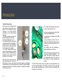
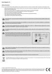
Hitch Climbers’ Guide to
the Canopy
Guidance for the use of the certified Hitch Climber System
Table of Contents
Table of Contents
Introduction
3
Disclaimers
4
HC Pulley Nomenclature and Standards
5
OP Hitch Cord Nomenclature and Standards
6
Ultra O Karabiner Nomenclature and Standards
7
Braided Safety Blue and Tachyon Nomenclature and Standards
8
Friction, Cord Selection and the Hitch
9
Less Sit Back, Easier Self-Tailing
10
Why certify the system?
11
Suitable and sufficient measures
12
Single Anchor Set Up, Some Features
14
Misconfigurations
15
Tolerance of Anchor Diameter/ 3F’s – Forks Falling and Fairlead
16
Double anchor Configurations
17
Managing Slack
18
Floating Prusik
19
Managing Slack
20
Rescue and hauling functions
21
Add-in Prusiks
22
The “Lift Off” Add-In Prusik
23
Comments Regarding Pick-Off Rescue
24
Equipment Hauling
25
Additional Applications
26
Contact Details
27
Introduction
The Hitch Climber Story
Some years ago, Treemagineers did
some testing on the strength of configured work positioning systems
commonly in use. Three situations
concerned us, all of which involved
karabiners:
• the width of loading on the main attachment karabiner, and the way
the load was distributed ¼-¼-½ ;
• the negative effect that a close and/
or large anchor had on the location of
cords within the main attachment
karabiner and the consequent reduction of strength of the karabiner
• the on/off loading pattern experienced during ascending by the hitch
karabiner when two attachment karabiners were used, with the increased
probability of cross loading.
With these three main issues and
many other objectives in mind, we set
about trying to come up with a solution. At first we made a few prototypes
ourselves which we took to manufacturers for comment. Following a lengthy
development period and an interesting diversity of subsequent prototypes,
we finally have a result.
Introduction
The certified Hitch Climber System has a
number components at its’ core:
•a rather sexy looking pulley called ‘Hitch
Climber’ from DMM in Wales;
•a symmetrical oval karabiner from DMM
called Ultra O;
•a high performance friction hitch cord
named ‘Ocean Polyester’ made in two diameters by Austrian manufacturer Teufelberger; and
•two climbing lines from Teufelberger Braided Safety Blue and Tachyon
These are stand alone products and each
carry their individual certification.
Together, they make a cracking combo for
tree climbers that prefer to use a knot as
their adjuster in running (doubled) rope
systems.
The Hitch Climbers Guide to the Canopy offers some thoughts about how to
use these products together. This ‘Guide’ is meant to help you formulate
your own safe working practices. It should be viewed in combination with
the system user instructions.
This is where things start to get official!
The Hitch Climbers Guide is not a User Manual. Manufacturers have no
obligation to offer more than the product information that comes with each
component. End users, however, know the limitations of most
User Instructions. We wanted to do a bit more to help communicate our visions of how this system could work, to help you understand why some of
the new features are there, and how these products may combine to help
work positioning in the complex structures that are trees.
Now the difficult bit.
As soon as we offer information, out of the darkness jumps the spectre of
liability. We hope that you will accept what you find in these pages in the
spirit in which it is offered, not as definitive instruction nor as a substitute for
training, but perhaps as an extra tool or two that could be added to your
mental tool box. The usual analysis, cross checking, discussion and peer
review should be applied to any new data you find here. We want to meet
as many of you folk as possible in person and in pleasant circumstances,
not in court or in hospital.
Please apply logic to what you do at height, the consequences of a mistake
or bad choice can be very harsh on individuals and families. Chose your anchor points wisely, make sure all the components in your work positioning
systems are compatible and suited to the work to be carried out, and ensure
that every component is configured correctly. If you are not sure about
something, before you do it, ask someone who is truly competent for their
input. The inherent risks associated with work at height are without doubt
Disclaimers
there, but that doesn’t mean you can’t enjoy safe work positioning with a
Hitch Climber System.
Manage the risks and enjoy!
Only some of the possible techniques are shown in this guide. Nevertheless
they cover simple and more complex work positioning techniques, rescue
and hauling applications, plus additional ways that the pulley can be used in
lightweight rigging.
If you have any difficulty in understanding the information presented, please
make contact with us.
Warning!
Work at height is a high risk activity.
It is your responsibility to manage those risks.
Before using these products you must:
• Inspect all components for defects;
• Read and understand all relevant user instructions;
• Understand the scope of application of the product and its’ limitations;
• Recognise, register and manage the risks involved; and
• Gain instruction from competent personnel.
Risk of serious injury or death.
4
The Hitch Climber Pulley
Standards: EN795(b):1996, EN12278:1998, NFPA 1983 (06Ed)Class L
Nomenclature
Loading diagram
Attachment holes
30 kN
30 kN
30 kN
Fairlead flare
30 kN
30 kN
Bushing
Pulley sheave
HC Pulley Nomenclature and Standards
15 kN
15 kN
5
Ocean Polyester Friction
Hitch Cord
Standards: EN566:2006, EN795(b):1996
Cord Type
Standards
Minimum Breaking Strength
(All tests on 12mm pins)
Polyester/ Aramid Mantle
Single
Mantle Intact
Product information
Protection sleeve
Doubled
Mantle Com6 coil Prusik on
pletely Sev- Braided Safety Blue
ered
and Tachyon
Ocean Polyester
8mm eye to eye
sling
EN795(b):1996
20kN
10kN
Ocean Polyester
10mm eye to
eye sling
EN566:2006
EN795(b):1996
28kN
14kN
Minimum Grab
Strength
15kN/3mins
Mantle Intact
23kN
15kN/3mins
33kN
6 coil Prusik on New
England Braided
Safety Blue and
Tachyon
4kN/3 minutes
4kN/3 minutes
Stitching
Aramid fibres (yellow)
Polyester fibres (red)
OP Hitch Cord Nomenclature and Standards
6
Ultra O Karabiner
Standards: EN362:2004, EN12275:1998, EN795(b):1996
Nose
Opening
Hinge
Nose slot
Locking mechanism
Barrel
Major axis loading
Body
Hinge
Minor axis loading
Spine
Gate
Locking mechanism
Body
Gate open loading
Product marking
Individual serial number
Ultra O Karabiner Nomenclature and Standards
7
Braided Safety Blue &
Tachyon
Standards: EN1891 Type A
Nomenclature
Tachyon
EN1891A Information
Braided Safety Blue
11.2
Rope Diameter mm
12.7
2.2
Elongation %
3.2
58.2
Cover mass %
83.6
41.8
Core mass %
16.4
86.4
Mass per unit length (g/m)
107.6
26.7
Static strength without
termination (kN)
Braided Safety Blue (stopper knot must be present at least 500mm from the end of the rope)
26
Polyester
Sheath material
Polyester/ MFP
Nylon with Polypropylene core
Core materials
Nylon
EN 1891 Type A
Standards
EN 1891 Type A
Eye termination
Product information label
Whipping
16 strand polyester mantle
Tachyon (stopper knot must be present at least 500mm from the end of the rope)
Strength with Figure 8 knot (kN)
Strength with spliced
termination (kN)
≤6
FF 0.3 impact force (kN)
≤6
Eye
termination
Safety Blue and Tachyon Nomenclature and Standards
24 strand polyester mantle
Product information label
Whipping
8
Friction, Cord Selection and the Hitch, or ....why you
should use a Hitch Climber System!
Running a climbing line over a branch splits the friction in a climbing system between the anchor
hitches e.g. Distel or V.T. The coils at the top of those hitches is where the friction is
point and the friction hitch. If you use a friction saver, you will have noticed how much quicker
concentrated. The pattern of braid(s) below decides how the friction is presented to the climbing
the cord of your friction hitch is now wearing. With more friction now concentrated at the hitch,
line. There are many configurations for each friction hitch but, as ever when trying new tools,
much more heat is generated there. The situation becomes more extreme with smaller diameter
stay low until you are truly competent with the system before advancing to greater heights. Take
climbing lines combined with small diameter
the time to match the hitch cord to the
hitch cord. Simply, the friction stays the
climbing line and make sure the hitch grips
same, but the surface area that copes with
reliably. Be particularly careful when using
the heat generated is smaller. This is
both a new hitch cord and new climbing line.
especially true if you climb somewhat
Try to use at least one ‘run in’ rope element.
‘sporty’ and are using a ‘pulley saver’.
Hence Ocean Polyester. The mantle
performance is delivered via a mix of heat
resistant Aramid and grippy Polyester. The
core is 100% trusty Polyester.
Ocean Polyester is available in spool lengths
and as stitched ‘eye to eye’ slings. The
slings meet EN standards having an MBS of
≥20kN. The result is the first knot based
system where every component is certified,
Hitch Climber works with most friction
whether it be the rope and its splice, a
hitches, but ultimately it’s up to you, the end
karabiner or pulley, cord and its terminations.
user, to configure the system so that it works
reliably. Single leg hitches (e.g. Blake,
Helical, etc ) will obviously require a stronger
cord than closed, double leg systems in
order to achieve the same strength. To really
benefit from Hitch Climber, use a hitch with
low ‘base friction’ such as the braided
Friction, Cord Selection and the Hitch, or ....why you should use a Hitch Climber System!
A good overview of arborists knots, including
friction hitches is:
Lingens, D. (2006) Tree Climbers’ Knotbook.
Schlauverlag, Stockelsdorf, Germany. ISBN
3-9810417-1-2. Available online at
www.freeworker.de
9
Less Sit Back, Easier Self-Tailing
‘Sit back’ is the backward/downward movement
(base friction), efficiency of the pulley sheave, the degree to which the system bends the
experienced by the climber between advancing an
climbing line and the weight of free hanging rope directly below the climber. Hitch climber
adjuster back to the point where the climbers
systems tend to leave the rope relatively straight and the rolling resistance of the sheave is low,
weight is held by that adjuster. For mechanical
hence self tailing occurs sooner.
adjusters, the measurement can be as small as a
few mm. For friction hitches the measurement is
normally in cm.
There is less “sit back” with a Hitch Climber
system. The hitch is pushed by the top of the
pulley. The hitch cord terminations are held at the
Why Certify the System?
The Hitch Climber System came about because Treemagineers wanted to coordinate, and
demonstrate, some of the amazing abilities of doubled (running) rope systems with friction
hitches. That original objective remains. Legislation and logic sit alongside that original passion
as motivators for certification.
base of the pulley. The distance between the top
Increasingly, national health and safety organizations, insurance companies, contract specifiers,
and bottom of the pulley is the minimum reduction
employers and end users demand some sort of verification that the tools being used are
in “sit back”. It is also possible to use shorter cord
appropriate for the task. Commonly, in Europe at least, EN standards are seen as the
lengths, so “sit back” is further reduced. Less “sit
back” = energy saved, so it’s worth experimenting
benchmark, and the presence of a CE mark is a legal requirement when selling Personal
Protective Equipment within the European Union.
with your hitch to see how you can reduce “sit
back”, whilst maintaining a reliable grab function.
Once you’ve achieved Nirvana, all you have to do
is remember the set up and order the same
lengths slings next time!
Key requirements of the EN standards are that:
• components are compatible with their neighbours;
• each component is configured correctly;
• equipment is strong enough for the job it is specified to do;
‘Self tailing’ is influenced by many things e.g. the
friction between hitch and rope when not loaded
Less Sit Back, Easier Self-Tailing
• ergonomic considerations are taken into account; and
• suitable and sufficient information is available to the end user to enable correct and safe use.
10
Why Certify the System?
There is no EN standard that directly applies to doubled (running) rope systems for connection
Strength Tests
to the ventral attachment point of a work positioning sit harness for industrial purposes. For
Minimum Static system strength – 23kN for 3 minutes;
that reason, certifying both components and complete systems is less straight forward than for
Minimum Dynamic system strength – 2500mm impact load with 100kg test mass; and
some other techniques.
Minimum Dynamic system strength – 600mm impact load with 280kg test mass.
Each individual component of the Hitch Climber System has
been certified to at least one EN standard and therefore
carries a CE mark. The system as a whole has been
certified to a ‘Manufacturer Standard’ developed by
Teufelberger working in close association with both
Treemagineers and DMM. Independent verification of
performance has been overseen by the Notifying Body TÜV,
Vienna. Hitch Climber Systems also carry the CE mark, as
a demonstration of their abilities. The key performance
criteria of the Manufacturer Standard can be summarized as
below:
Function Tests
Grab function test 1 – 4kN five times after advancing the friction hitch (single rope);
Grab function test 2 – 4kN for 3 minutes (single rope);
Controlled descent with a 150kg mass; and
Controlled descent with a 280kg mass.
Why Certify the System?
11
Suitable and sufficient measures
In addition to certification tests, Treemagineers carried out further test series that more closely
mimic the conditions experienced by the friction hitch cord under working use. One series
assessed the strength of Ocean Polyester 10mm eye to eye slings after a number of different
‘low load/high cycle’ regimes.
The results can be seen in the tables below:
Fixed load (0.6kN) over a range of cycles
Number of Cycles
Retained strength after low load cycles
10 000
>22kN
20 000
>22kN
40 000
>22kN
60 000
>22kN
80 000
>22kN
100 000
>22kN
Fixed number of cycles (40 000) with a range of loads
Load (kN)
Suitable and Sufficient Measures
Retained strength after low load cycles
0.9
>22kN
1.2
>22kN
1.5
>22kN
1.8
>22kN
2.1
>22kN
2.4
>22kN
2.4 (180 000 cycles)
>22kN
12
Suitable and sufficient measures
It is widely believed that rope-on-rope abrasion is a problem. This can be true when component
The rope-on-rope tests help demonstrate that:
compatibility and correct configuration have not been assured. Equally, poor end user habits
• When correctly specified, friction hitch cord can be both reliable and long lasting when used
can lead to accelerated wear e.g. cordage glazing may result from excessively fast descents.
Treemagineers tested Ocean Polyester friction hitch cord in different ‘simulated descents’. For
each ‘descent’, 20m of rope was passed through a friction hitch (six coil Prusik) as a 50kg mass
was lowered on a single line. (This is approximately equivalent to a 10m descent with 100kg
mass attached to doubled system).
Three rope speeds were used, equivalent to 1m/s (fast descent), 2m/s (full speed descent) and
3m/s (out of control) descents on a doubled rope system. Between each ‘descent’, the Prusik
was taken apart and assessed for abrasion damage. The test was stopped when the Polyester
as a rope adjuster;
• Increased speed of descent has a clear detrimental effect on the lifespan of friction hitch
cordage;
• Lifespan may be equal to, or better than, that of metal wear parts in mechanical adjusters;
and
• Rope-on-rope is not necessarily a problem.
By sharing Treemagineers test results in combination with outlining the certification process, we
hope to have established that suitable and sufficient care has been taken to ensure that both
of the mantle had been sufficiently abraided that the ‘tactile gradual control’ of the friction hitch
the components and the system are appropriate for the tasks intended. Does this mean the
had been altered to that of an ‘on/off switch’. At this point, the number of descents was noted
system is perfect? Of course not! Does this mean the user can delegate all responsibility to the
and the length of rope passing through the friction hitch was calculated. It is important to note
that the mantle had not been ruptured. The Aramid component remained, therefore the cord
system? Again, obviously not! The contribution to safety and efficiency that we feel has been
made by certifying the Hitch Climber System, is to eliminate some of the variables that can lead
retained considerable strength and its’ tolerance to heat. The function of the friction hitch had
to accidents and to provide a flexible platform which can be used as a base for many work
however altered, to the point where a climber might want to exchange it, but solely because of
positioning possibilities. If all components are well suited to the task(s) they perform and to
its handling characteristics. The results are included in the table below:
functioning with each other, the user can concentrate on their part of the safety equation more
Speed of Descent
Length of Rope through the Friction Hitch Prior to loss of “tactility” (m)
karabiners, the wear and tear on components and ensuring good quality work positioning
1m/s
≥1000 (test stopped due to time constraints)
2m/s
≥220
they be in an office (e.g. health and safety staff, contract specifiers, Responsible Persons) or on
3m/s
≥40
site (e.g. Competent Persons, tree climber, designated rescuer).
Suitable and Sufficient Measures
easily e.g. monitoring the grab function of the friction hitch, the closing and locking of
before performing a task, etc.
With a Hitch Climber System, all personnel can be confident about its’ specification, whether
13
Work Positioning Techniques
Climbing line – Standing side
Climbing line – Running side
Single Anchor Set Up, Some Features
Eye to eye friction hitch sling
The stitched terminations on OP slings make the whole system more compact, and the rope
Friction hitch upper coils
termination is now relocated to a second karabiner. The compactness allows us to use a
different shape karabiner for main attachment. An oval karabiner here has the advantage that it
can accept wider loads at both ends, so it can be rotated if desired. The load from the splice is
transferred through the rigging plate of the pulley to a central position on the Oval karabiner
where the loading pattern is now ¼-½-¼, which plays to its strengths. Oval karabiners loaded
like this often break above their rated MBS. When the climbing line is in tension, both
Constriction band
karabiners tend to be pulled into vertical alignment. When ascending, slack may form in the
Friction hitch lower braids
Eye termination
rope below the point where you grip, but the loading on the hardware is maintained. Visual
inspection of the system is also clear and simple.
Note:
Upper oval karabiner
Stitched eye
Measures should be taken to ensure that karabiners remain loaded along the main axis at all
times, this is especially difficult during inconsistent loading patterns. Reliable methods may
include fasts or compression fittings (e.g. Sherrilltree’s Blue Band-Its), tight spliced or stitched
terminations.
Hitch Climber pulley
Low profile terminations should be used at the standing part of the climbing line. Conflict
between the friction hitch and climbing line end knots may cause the friction hitch to perform
Constriction band
inconsistently.
Lower oval karabiner
Single Anchor Set Up, Some Features
14
Misconfiguration
Misconfigurations
Knotted termination interfering with
correct hitch function
Misconfigurations
Cross loading of karabiner due to
non-captive eye of termination
Stopper knot tied behind an attachment
hole
Directly tied into an attachment hole
15
Work Positioning Techniques
Tolerance of Anchor Diameter
3F’s - Fork Falling and Fairlead
The upper karabiner holding the
A pulley directly under the friction hitch tends to
termination is able to swing in its’
ensure that the rope is always fed to the
attachment hole. Anchor points of all
underside of the friction hitch in a similar way,
sizes can be accommodated
thus normalizing hitch function. Rope fed at an
without having to reconfigure
angle to the cheek plates of the pulley will tend to
equipment or accept a
be guided onto the running sheave via the side
compromised system. This includes
flairs and cheek plate angles.
‘climbing in a triangle’ where the
rope is routed over two anchor
points, often some distance apart.
Extended circular cheek plates tend to ensure
that the rope continues to run on the sheave
even when the rope is being fed from a slight
angle. When a climber descends in the canopy,
the running rope is often bent over a branch or
through a branch fork. The rope is thus bent
upwards as the climber descends.
There is no way to avoid friction building up on
the branch, but the Hitch Climber pulley (without
a “becket”) helps to ensure that only minimal
running resistance is added by the pulley
Tolerance of Anchor Diameter/ 3F’s – Forks Falling and Fairlead
16
Double anchor Configurations
Two Anchors, One Hitch, One Rope – the “V” rig
reassuring technique to adopt in bad weather. For
A great technique to have in the tool box. With low running resistance pulleys at both anchors
example, returning from a branch walk on a snow
and at the top of the hitch climber, the load placed on both anchors tends to be equalised. This
covered limb may be considerably more graceful
technique may be applied in trees that have been topped (e.g. where the climber feels uneasy
than the alternative of fearful skating!
about anchoring on a single point) and in trees with spreading crowns. Traversing from one side
Notes:
to the other (and back) may be easier. It also gives more confidence when working in the wet.
These are not basic techniques. Training may be
Branch walking (in and out) seems to be easier. This
system can also be very useful when cable bracing
e.g. traversing from one point to another and then
back to the original location to complete a ring
brace.
Double Anchor Configurations
should be practiced at
low level. Many repetitions may be necessary. When
the climber is competent in the individual technique
he/she may advance to a working position. Direct
Two Anchors, Two Hitches, Two Ropes –
supervision by other climbing staff, who are
double crotching
competent with the Hitch Climber system, may
Climbing with both ends of a climbing line (or with
continue to be necessary.
two ropes) is preferred by many, but that can lead
Friction at the hitch may be less than normal levels.
to lots of clutter at the front of the harness. In this
The hitch may need to be modified to perform reliably. To help ensure anchor forces are
configuration, the second climbing system is
equalised, anchor points must be at the same height.
mounted in the spare hole of the lower Hitch
Adopting a swivel unit at the harness attachment point is recommended for these techniques.
Climber pulley. There is only one karabiner attached
It’s all too easy for torsion to build up in all that hardware concentrated in such a small area –
directly to the harness.
Two anchors, one hitch
essential or advisable. New or unfamiliar techniques
Two anchors, two hitches
not good! It is important to avoid placing large lateral loads on the anchor points. Lateral loads
Traversing and precise work positioning can be
increase as rope angle approaches horizontal.
made easier using this system. Again, this can be a
Anchor points in trees are often poorly adapted to lateral loads.
17
Managing Slack
Slack can be bad for your health! It has a habit of accumulating without you realising, normally
at those times when the consequences of a fall would be most serious. However, with a bit of
good house keeping and a few well chosen techniques,
slack can be tidied away!
All feet on rope!
Using foot ascenders, your upper
body can be given a break from time
to time, and those powerful muscles
in your legs can take over.
Slack Tending Pulley
Foot ascenders and slack tending
Hitch Climber is a cracking slack tending pulley! It’s
pulleys belong together like coffee
right there underneath the friction hitch, held tightly in
and cake.
position between the two connection karabiners.
The sheave’s large tread diameter, the fairlead flairs, the
proximity of the pulley to the friction hitch and the lack
of sloppiness means that Hitch Climber is pretty
efficient at this job.
Simply pull the climbing line underneath the pulley and
slack is removed.
All Hands on Rope!
This may not be sexy, new or cool, but it is effective.
Reach up with one hand above the hitch on the running
part of the line, place the other just below the Hitch
Climber.
Climbing with a foot ascender
Now pull down with both hands at the same time (and
maybe give a little hip thrust too). True enough,
progression is slow, but it is steady, confidence
inspiring and slack free!
Avoiding slack in the climbing system
Managing Slack
18
Managing Slack
Floating Prusik
Other advantages are that one connector is removed from the system, thus making the climbing
This technique is perhaps best suited to bigger spreading
system simpler. The configured strength of the Floating Prusik system as shown is very high.
trees, whose form dictates that short periods of work in the
Notes:
periphery of the crown are repeatedly followed by a long
Pay attention to ensure that the friction hitch is always within easy reach and that the friction
inward limbwalk and an ascent, before traversing to the
periphery again. But this loop system is so quick to
configure, it could be used in any tree.
The big advantage is that the friction hitch can be positioned
at ‘ascent/inward limbwalk’ or ‘positioning’. The transition
from one mode to another takes only seconds. When
hitch grabs reliably.
In our image to the left, we have used a Wild Country Ropeman 1 to hold the loop in position.
We have used this ascender because it is compact, light, relatively cheap, plus it allows rope to
move in both directions without snagging. There are other mechanical devices that fulfill these
criteria. A compact Prusik is another cheap and equally functional alternative (see below).
‘ascending’,
the friction
hitch is floated
a suitable
distance away
from the climber and ‘anchored’, so that long
pulls can be made with both arms. Slack, that is
so often a feature of systems where the hitch is
close to the climber, is therefore almost
eliminated. For ‘positioning’, the friction hitch is
rolled as close as possible to the climber and
anchored again, with the objective of enabling
precise hitch control in all work positions.
Floating Prusik
19
Managing Slack
For systems that use mechanical adjusters to anchor the loop, there is a tendency for the loop
saver enables a mechanical advantage system that not only makes ascending easier, it also
system to ‘roll’ when inward branch walking whilst taking in slack i.e. the friction hitch moves
eliminates slack. Two birds, one stone, or in this case, a beautifully crafted collection of high
away from the climber. If a bit of weight is kept in the harness/climbing line, ‘roll’ can be
grade components!
eliminated. Equally, if you have a hand free, you could hold the bite of rope at the sliding D to
stop rotation. This issue does not occur when a compact Prusik loop is employed to anchor
The ‘Descending Branch’ MA
A few uncomfortable inward steps, bit of
the loop.
The length of the eye termination should be dimensioned so that when in ‘positioning’ mode, a
‘bite’ can be formed in both legs of the eye.
The splice itself should not be bent to form
the bite.
a wobble, take out the slack in a hurry!
Returning from a descending branch at
the extremities of a broad canopy can be
a tricky operation, and contain a few
anxious moments, especially in slippery
Mechanical Advantage Returns
If you were looking for an excuse to buy a
locking DMM Revolver, these techniques
justify the retail therapy!
conditions! If you place that Revolver on
a suitably strong and well placed branch
during the outward limb walk, you have a
mechanical advantage system that helps
the return in more than one way:
The ‘Conifer Dismantle’ MA
Climb up, establish an anchor point,
descend to the lowest braches, start cutting
on the slow journey back up. It often makes
sense to follow this sequence when
dismantling conifers (or other trees
• there are two legs of rope to lean
against, so balancing is easier;
• slack is eliminated;
• progress is faster;
• and less effort is required.
exhibiting strong apical
dominance).
Slack can be a feature of those
short ascents between work
stations on the way back up to the
anchor. However, a pulley (read
Revolver) placed near the friction
The ‘Conifer dismantle’ MA
Managing Slack
DMM’s “Revolver” Karabiner
The ‘Descending Branch’ MA
20
Rescue and hauling functions
Lifting the casualty
‘Pick-off’ rescue
In Hitch Climber systems, there is a pre-installed 3:1,
In a Pick Off rescue, the mass of the casualty and any
braked, mechanical advantage hauling system on the
extra material required for the rescue (such as a
climber at all times - a passive safety feature. This is
stretcher/litter) is entirely supported by the rescuers
relevant where the casualty may be located vertically
work positioning system. The load applied to the
above a hazard or poor landing zone e.g. electrical
friction hitch of the rescuer is significantly increased.
power lines, water or road. By hauling on the running
There may be difficulty in operating the hitch, leading to
part of the climbing line, the casualty may be raised
a tiring and/or jerky descent.
higher in the canopy above obstacles, then lowered
Friction levels can be reduced at the hitch and
following a different route to a more suitable landing
relocated elsewhere to ‘normalise’ the performance of
zone.
the hitch. An adjustable mid-line attachment can be
Note:
added above the spliced termination using a compact
Rescue should only
Prusik loop. Varying levels of friction can be added by
routing the running part of the climbing line through a
be attempted using
Basic connection to injured climber
karabiner or by connecting friction devices to the
the casualty’s
Rigging a 6:1 hauling system
climbing line if
karabiner e.g. a belay plate. If the climbing line is long
enough, friction can be created by a ground worker
inspection shows the whole system (including anchor point)
tending the tail of the rope until both rescuer and casualty are on the ground.
to be fit for use following the incident. Ensure that the rope is
long enough to complete the descent. Rescuer and/or
Notes:
groundworker should provide a backup brake on the hauling
Forces placed on anchor points and throughout the work positioning systems are often
line.
considerably higher in a Pick-off rescue than in normal work, especially if the descent is jerky.
These forces should be taken into account before attempting to simulate a Pick-off rescue and
Pre-installed 3:1 hauling system
Rescue and Hauling Functions
21
in crisis situations. A change to a
discussed, a few more examples are shown here.
stronger anchor point may be
The ‘Stay Connected’ Add-In
necessary, and different hardware
When setting up a Triangle or ‘V’ Rig, it is common to use a second system (such as an
and textiles may be required in the
rescue system. Many other
combinations of equipment may be
used to add friction in this
scenario. It is the users
responsibility to ensure that the
equipment chosen suits the
requirements of the situation.
Adding friction for a pick-off rescue
adjustable lanyard) to attach to a stem whilst the main climbing system is disconnected and
reconfigured. Using an Add-In Prusik, the main climbing system may continue its safety
function throughout the reconfiguration, in addition to the use of a second attachment:
Image 1) Install a Prusik on the standing side of the Hitch Climber System and connect it to
the upper hole of the pulley (ensure the grab function of the Prusik is reliable);
Image 2) By alternately adjusting both friction hitches, create slack in the section of climbing
line between the add-in Prusik and the Hitch Climber pulley. When sufficient slack has been
created, tie a mid line knot (e.g. Alpine Butterfly) as a stopper knot below the Prusik. Check
When adding friction after the
that the middle karabiner is now unloaded before disconnecting the spliced termination of the
friction hitch, the additional
climbing line;
components and changes in
Image 3) Use the free end of rope to establish a second anchor, this may be a natural crotch
component orientation can lead to
or a friction saver. Reconnect the spliced termination to the middle hole of the Hitch Climber
difficulties in ensuring normal control and function of the friction hitch. Take extra care to ensure
that:
• descent is controlled;
• some friction is maintained in the top coils of the friction hitch;
• friction is balanced between the friction hitch and the added
friction device;
• the friction hitch is free to return to its grab position; and
• predictable manipulation of the hitch is possible.
Add-In Prusik
We’ve had problems finding where to put this section! Add-In
Prusiks can be added during rescue or work positioning
operations, single anchor or double. Rather than have a crisis
about it, we decided to add on an Add-In section! Add-In
Prusiks can take many forms, some have already been
Image 1
Add-In Prusiks
Image 2
Image 3
Image 4
22
Add-in Prusiks
pulley using a karabiner. Remove the midline knot from below the Add-in Prusik, and
attachment on the Casualty’s harness.
alternately adjust both friction hitches to remove all slack from the system; and
The Rescuer may now ascend a short distance from the Casualty and tension the Pick-off
Image 4) after a newly configured Triangle system is proof tested, it may be possible to
system. When the Rescuer descends, the Casualty may now be lifted (depending on the
redirect the climbing line further, thus involving more of the structural canopy of a tree(s). If the
relative masses of the two climbers. The Rescuer can aid the lift by pulling on the standing
Add-In Prusik is passed through the redirect fork each time, it may not be necessary to
part of the line below the Add-In, which is connected to the Casualty. In this way lighter
remove it from the climbing line before the next redirect. The Add-In Prusik can remain
Rescuers may lift heavier Casualties. The counterbalance effect is most efficient when friction
connected to the spare hole on the Hitch Climber so that it doesn’t swing around doing
is low at the Rescuers anchor point.
damage (e.g. broken teeth or
glasses!)
The ‘Lift Off’ Add-In
During a ‘Pick-Off’ rescue it
is sometimes necessary or
desirable to lift the casualty.
Whilst this can be easily
achieved using mechanical
advantage systems, a simple
counterbalance can be set
up using a Hitch Climber
system plus an Add-In
Prusik.
When the Rescuer has
reached the Casualty, an
Add-In Prusik is securely
placed above the spliced
termination on the standing
part of the climbing line. The
spliced termination is then
connected to a suitable
Descent to injured Climber
The “Lift Off” Add-In Prusik
Termination of climbing line attached to injured
climber. Rescuer descends on add-in prusik
Descent on main friction hitch, added friction
necessary
23
Add-In Prusik
Comments regarding Pick-Off rescues are also relevant here. Please cross reference with that
section including the Notes.
Note: The Add-In Prusik must be tied, dressed, set and tested before disconnecting the
standing tail of the climbing line. Place a mid-line knot (e.g. Alpine Butterfly) below the Add-In
Prusik before disconnecting the spliced termination.
If the Add-In is retained on the climbing line, ensure it does not negatively affect the reliable grab
of the main friction hitch.
Ensure that each anchor point is strong enough (with ample safety reserves) to cope with the
range of planned and unplanned loading scenarios that could occur during its use.
Very important:
Practice and become competent at ground level prior to using new techniques at height;
Whenever connecting and disconnecting at height, take considerable care to ensure that at
least one connection to a structural anchor point is maintained at all times; and
If you have any questions, please make contact before adopting a new work practice!
Comments Regarding Pick-Off Rescue
24
Equipment Hauling
Hauling equipment up to the canopy of a tree can be tiring work. With a Hitch Climber system,
the climber can pull a bite of rope from between the hitch and pulley then lower it to the ground
Additional Applications (in brief)
worker. Tools (e.g. chain saw, pole saw, rigging equipment) or other supplies (e.g. bracing
equipment, lunch or water!) can be attached in the loop and then be pulled up to the climber
(using mechanical advantage).
Hitch Climber pulleys are available in a range of specifications (e.g. with bushings and bearings),
all with aluminium sheaves. A range of cheekplate and sheave colours help to differentiate
specifications and function e.g. PPE or lightweight rigging.
The ground worker pulls on the tail of the rope, the
loop shortens and the tools go up to meet the
climber.
Karabiners incorporating a pulley e.g. DMM Revolver
Locksafe increase the efficiency of the system when
used to hang the load. It’s never been so easy (for
the climber) to get that Stihl MS660 in to the tree!
Hitch Climber Pulley with low-friction bearing
Equipment Hauling
25
Additional Applications
Single pulley speedline
Mechanical Advantage Systems
Simple speedline installation for lightweight loads. Load suspended centrally. Haul back and pull
Mechanical advantage systems are normally constructed using
lines to either side. Hitch Climber is certified as an anchor for Horizontal Life Line systems.
multi sheave pulleys. Because Hitch Climber can be hung
eccentrically, braked MA systems can now be built with single
sheave pulleys.
Multiple pulley speedlines
Chain of Hitch Climbers spreads the load along a greater length of rope. The benefits are less
bending of rope at any one point, plus multiple attachments to the load. Haul back and pull lines
at ends of chain.
Rigging a mechanical advantage system
with Hitch Climber pulleys
... yet another use for your Hitch Climber pulleys!
Additional Applications
26
This Guide has illustrated some examples of appropriate uses of the Hitch Climber system.
We’d love to hear what you think!
If you have suggestions for further techniques please take the time to put them in writing, with
copious illustrations, as much explanation as possible and contact details including a telephone
number. Our contact details follow below.
The plan is to expand the Hitch Climbers Guide with your help and experience, for all to share.
Teufelberger Ges.m.b.H.
Vogelweiderstrasse 50
A-4600 Wels
Austria
www.teufelberger.com
DMM International Ltd
Y Glyn
Llanberis
LL55 4EL
Wales – GB
www.dmmwales.com
Treemagineers Ltd
Dall Store
Rannoch Station
PH17 2QH
Scotland – GB
www.treemagineers.com
Contact Details
27
Images courtesy of: Tim Bridge, Chris Cowell, DMM International, Knut Foppe, Pascal Künzler, Florian Nidecker, Giovanni Ugo. All line drawings M. Bridge. © by Treemagineers/ M. Bridge 2009