1
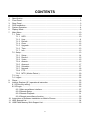
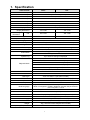
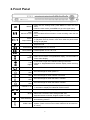
16CH H.264 Digital Video Recorder User’s Manual STANDALONE DVR SYSTEM 2011 MAY V1.2 WARNING Do not expose the DVR under the sunlight, heat or wet environment while installation. As it could decrease the performance of DVR and damage the machine. Do not touch the power plug or case with wet hands as this could result electric shock. Do not forcedly bend or put heavy object on power cable as this could result in injury to personal or equipment. Do not operate with damaged power cord or loose electrical outlet as this could result in electric shock or accident. Please use individual power instead of share electrical outlets with other electrical equipment as this could result in damage or accident. Do not attempt to service this DVR by yourself as it may expose you to dangerous voltage or other hazards. Please refer all service to the qualified servicing distributor. Do not open the covers or insert any object into DVR. CAUTION Do not place the machine on an uneven surface or it would decrease the DVR efficiency or malfunction. Avoid any shock or bumping of the DVR while recording. Improper handling could damage the system. CAUTION Make sure the voltage selector switch (100V/240V) is set to appropriate setting before plug in! ii CONTENTS 1. 2. 3. 4. 5. 6. 7. Specification ................................................................................................................. 1 Front Panel ................................................................................................................... 2 Rear Panel ................................................................................................................... 3 DVR Installation ............................................................................................................ 3 System Operation ......................................................................................................... 4 Display Mode................................................................................................................ 6 Main Menu.................................................................................................................. 10 7.1 Tools .................................................................................................................... 10 7.1.1 HDD ......................................................................................................... 10 7.1.2 User ......................................................................................................... 11 7.1.3 Default...................................................................................................... 12 7.1.4 Clear ........................................................................................................ 12 7.1.5 Upgrade ................................................................................................... 12 7.1.6 Time ......................................................................................................... 13 7.1.7 Info ........................................................................................................... 13 7.2 Setup ................................................................................................................... 13 7.2.1 Setup........................................................................................................ 14 7.2.2 Record ..................................................................................................... 15 7.2.3 Video ........................................................................................................ 15 7.2.4 Alarmin ..................................................................................................... 16 7.2.5 Alarmout................................................................................................... 17 7.2.6 Schedule .................................................................................................. 17 7.2.7 Network .................................................................................................... 18 7.2.8 PTZ .......................................................................................................... 19 7.2.9 MTD ( Motion Detect ) .............................................................................. 20 7.3 Log ...................................................................................................................... 22 7.4 Logout ................................................................................................................. 22 8. Player ......................................................................................................................... 22 9. Internet Explorer (IE ) operational instruction ............................................................. 25 9.1 IE Security setting: ................................................................................................ 25 9.2 IE Login ................................................................................................................ 26 9.2.1 Main surveillance interface ......................................................................... 27 9.2.2 Remote Setup............................................................................................. 28 9.2.3 Remote Playback ....................................................................................... 31 9.2.4 Remote surveillance function...................................................................... 32 10. Instructions of Software Installation on Mobile Phones .............................................. 33 11. HDD Support List ....................................................................................................... 34 12. USB Flash Memory Stick Support List ........................................................................ 35 iii 1. Specification Video Format PAL Video Input 16 CH Input / BNC Audio Input 4 x RCA (CH4 Two-way Audio) Video Output 1 CH Output / BNC Audio Output 1 CH Output / RCA XGA Output 800x600、1024x768、1280x1024 Alarm Input 4CH Alarm In Alarm Output Buzzer,2 x Relay Out (N.O、N.C) Display Mode Full Screen, 4/9/13/16 CH Split Screen, Auto Switch Display Resolution Recording Resolution NTSC CIF Recording Frame Compression Algorithm 720 x 480 720 x 576 360 x 240 360 x 288 Max. 480 FPS Operating System Pentaplex Embedded Linux Record / Playback / Network / Mobile Phone / Back up Recording Mode Schedule Recording Manual, Schedule, Event Full Recording, Motion, Alarm, Manual Recording Status Indicator Event Mode System Log Max. 400 FPS H.264 Power, Network, HDD1, HDD2 Alarm Trigger, Motion Trigger, Video Loss Recording Duration: 1~60 sec. Up to 2000 recording list displayed Normal Speed: x1 Fast Forward: x2 / x4 / x8 / x16 multiple speed Playback Mode Slow Forward: 1/2、1/4、1/8 multiple speed Fast Rewind: x2 / x4 / x8 / x16 multiple speed Frame by Frame Playback: Forward Search Function: Time / Event Network Protocol TCP/IP / PPPoE / DHCP / SMTP / DDNS Inter-communication HDD Type PTZ Control Yes SATA 3.5”HDD x 2 (No HDD Included) Communication Protocol (PELCO P, PELCO D, MIKAMI) (RS-485) Backup Device Firmware Update Multi-Language Control Mode Network Control Network Function USB 2.0 Flash Memory Stick Host USB、LAN / WAN English/ Traditional Chinese / Germany /Russian/ French / Spanish / Italian / Portuguese / Turkish/ Japanese / Korean/ Simple Chinese / Czech Republic / Poland Front Panel / Remote Control / USB Mouse / Internet IE Browser / Multiwindow(CMS) Remote Control Live Display / Playback / PTZ Control / System Setup IR Extension YES (Optional) Power Supply DC 12V / 4A(AC100V~240V 50/60HZ) Unit Dimension 430mm (W) x 314mm (D) x 53mm (H) Weight 3kg ( HDD and Power Adapter Not Included) Operating Temperature 0℃ ~ 46℃ 1 2. Front Panel MENU Stop Manual Record Pause Step Forward Play Fast Rewind Rewind speed: x2 / x4 / x8 /x16 Fast Forward Forward speed: x2 / x4 / x8 / x16 Slow Forward Slow forward speed: 1/2、1/4、1/8 Up Down To move up or down of the selection setting in the menu. Under the live mode of Single/Quad/9 display, use the button to control video display. Left Right To move left or right of the selection setting in the menu. Change to Single/Quad/9/13/16 division display under the living mode. Enter Press the Enter button to confirm the setup or go into sub-menu. Power Indicator LED Network Indicator LED HDD 1 Indicator LED HDD 2 Indicator LED 0(+10)-9 Under the live viewing mode, press MENU to enter the main menu. Under the menu mode, press MENU to go to the upper menu. To stop the operation or go to the upper menu under the playback mode. Press the Manual Record button to start recording under the live mode. To pause the playback under the playback mode. To playback frame by frame in each time under the pause mode during the playback. Under the live viewing mode, press the Play button to enter the playback mode. The LED will light on when power on. The LED will light on when network connected. The LED will light on when the HDD 1 is written. The LED will light on when the HDD 2 is written. Channel 1~16 Under the live viewing mode or playback mode, press channel 1~16 button to display the individual channel screen. 9 / 16 CH Split 9 / 16 channel split screen display. Quad Auto Switching USB2.0 Slot Quad screen display. Select start / end time, when setting the MD area. Keyboard switch to number, English Capital or symbol. Under the live viewing mode, press the button to start/stop the auto switching function. For USB 2.0 Flash Memory Stick to Backup and Firmware Update. (There are a front and a back USB that can be used one at a time.) 2 3. Rear Panel 1 2 3 4 5 6 7 8 9 10 11 USB Mouse Port VIDEO IN VIDEO OUT AUDIO OUT AUDIO IN ALARM DC12V XGA LAN RS-485 HOOK 1.0 USB Mouse 1~16 CH Video Input (BNC) Video Output (BNC) Audio Output (RCA) 1~4 CH Audio Input ( CH.4 is for external input ) Includes 4 DI AND 2 DO (Default N.O.) Power Input LCD Monitor Output RJ45 Network Connection RS-485 Connection, For Speed Dome Use Cable Hook Alarm I/O Instruction Instruction Pin 1. CH 1 SENSOR INPUT Pin 2. CH 2 SENSOR INPUT Pin 3. CH 3 SENSOR INPUT Pin 4. CH 4 SENSOR INPUT Pin 5. Ground Pin 6. 1ST RELAY : COM Pin 7. 1ST RELAY : N.O ( Default ) Pin 8. 2ND RELAY : COM Pin 9. 2ND RELAY : N.O ( Default ) 4. DVR Installation Connect the camera video output to the DVR video input port with BNC connectors. The camera install coaxial cable is suggested RG-59 or above. DVR Network installation Please connect DVR to HUB or router by using RJ-45 network cable and make sure the DVR network indicator LED is on. (Please refer to 7.2.7 Network for further network setting information of using static IP, PPPoE or DHCP. ) Alarm Installation Please refer to 3. Rear Panel for external alarm I/O installation. (Please refer to 7.2.4 Alarm in & 7.2.5 Alarm out.) Speed Dome Installation 3 This product can be installed protocol (Pelco D, Pelco P, MIKAMI, LILIN, Samsung) Power Installation Please use the provided power cable and adaptor to connect the DVR (AC100V~AC240V). Please refer to 3. Rear Panel for connecting position. The DVR system will enter into live viewing mode when power is connected. Please refer to 6. Display Mode for more information. 5. System Operation There are 3 kinds of DVR control method: front panel, remote control and USB mouse. Please refer to 2. Front panel. Mouse Operation Right click the mouse button under the live viewing mode for enter into Quick Menu. Left click the mouse button under the main menu to go to menu selection. Left click the mouse button under the select menu to go to the sub-select menu. Right click the mouse button under menu selection to EXIT. Use the mouse or Virtual Keyboard to change the setting Remote control operation Please refer to 2. Front panel and the reference table of the button as below. Stop Lock Record Play Step/Pause Fast Rewind Slow Forward Fast Forward Remote ID Setup PTZ IRIS Zoom in/out PTZ Setup Remote ID Setup Mute Auto Switch Up Selection Left Selection Search Information Enter Right Selection MENU Down Selection Cancel 13 Disivion Display 16 Disivion Display 9 Disivion Display Quad Display Number 1-9, Channel 1-16(Switchable) 4 Virtual Keyboard Operation The text input of the virtual keyboard is as below: ※To key in data, press “Quad” button to switch to number, English Capital or symbol by using front panel or remote control. Front Panel & Remote Menu Operation Control Operation Select character from virtual Mouse Operation [Up/Down/Left/Right] [Move Cursor] Key in the select character [Enter] [Left Click] Exit the virtual keyboard [MENU] [Right Click] keyboard Key Description of Virtual Keyboard Num Capital letter shift 123 Number abc lowercase letter shift , Symbol Main Menu Operation Setup Operation Front Panel & Remote Control USB Mouse Select Item [Up/Down/Left/Right] [Move Cursor] Enter Select Item [Enter] [Left Click] Exit Main Menu [MENU & ESC] [Right Click] 5 6. Display Mode There are 3 kinds of screen display mode: Live, Auto Switching and PTZ. Live Viewing Mode The DVR will go to the live viewing mode after boot up. There are 5 different status icons: 1. :Record 2. :Motion Triggered 3. :Alarm Triggered 4. :Schedule Record 5. :Manual Record Setup Operation CH. 1~16 SINGLE DISPLAY 4/9/13/16 channel Split Display Quick Menu Playback Mode Start/Stop the Manual Record Start/Stop the Auto Switching Start/Stop the PTZ Auto Tracking Start/Stop Mute Front Panel & Remote Control [ Channel 0(+10)~9 and 1~16] Left click upon selected channel [4/9/13/16 Split] Left click upon UI Menu [MENU] [Right Click] Left click upon Recording data of UI Menu to operate Left click upon Manual Recording of UI Menu to select option [Play / Search] [record] and select option in Manual Recording of UI Menu [Auto Switching] USB Mouse Set Up in UI Menu Set Up in UI Menu Set Up in UI Menu [Mute] Set Up in UI Menu 6 Quick Menu Setup Operation Front Panel & Remote Control USB Mouse Select Item [up / down、right / left] [Moving Cursor] Enter the Select Item [enter] [Left Click] Exit [MENU / ESC] [Right Click] PTZ Please set the speed dome properly before control PTZ. Please refer to 7.2.8 PTZ for setup. Setup Operation Front Panel & Remote Control USB Mouse Select Item [up / down、right / left] [Moving Cursor] Enter Select Item [enter] [Left Click] Select PTZ Channel [up / down] [Left Click] Zoom +,- ZOOM + - Focus, +- Focus + - Iris, +- IRIS Adjust Movement Speed + - Fast、Normal、Slow PTZ Upward PTZ Downward PTZ Left PTZ Right Start/Stop Auto Tracking Exit [MENU] [Right Click] Auto Switching Auto switch starts from orderly CH1 to CH16, or split display orderly (exclude 13 and 16 split display). Manual Recording Enable manual: here shows selected camera’s status, setup and signal: Setup Operation Front Panel & Remote Control USB Mouse Select Item [right / left] [Moving Cursor] Enter Select Item [up / down] and [enter] [Left Click] Exit [MENU] or [ESC] [Right Click] 7 Signal Instruction :Not in recording. 1. 2. :In recording. 3. :Not in recording yet in internet surveillance. 4. :In recording and internet surveillance simultaneously. Recording Data option : playback and back-up a. b. c. d. e. Select channel (Selected item would be shown as light blue). Select recording mode: manual, alarm, motion and schedule. Enter Start and End time to search or playback. Select “search “and recording list be shown. Select from the list with mouse or remote controller to playback. f. Mouse right click to select (Multi-selection be available) from list for backup, for remote controller, with “INFO” to select or remove select (press Enter will playback the selected item directly), “Select all” to back-up all. g. Backup device:Select the backup path to device. 8 h. Select backup file type: ifv or avi. Ifv: Needs to be played by Player. Avi: Available to be played by other media player. Playback operation a. Afer set up a~c, press Playback to start the video like below picture; or continue d~f to select file to backup or playback. b. Instruction of Playback: Setup Operation Front Panel & Remote Control Fast Rewind [Fast Rewind] [Left Click] Fast Forward [Fast Forward] [Left Click] Step Forward [Step Forward] [Left Click] Step/Pause [Step/Pause] Play 1x [Play] [Left Click] Stop [Stop] [Left Click] Mute ON/OFF 1~16 Single Channel Display [CH. 1~16] 9 USB Mouse [Left Click] / / [Left Click] [Left Click] to select cannel; Another [Left Click] back 7. Main Menu Setup Operation Front Panel & Remote Control USB Mouse Select Item [up / down、right / left] [Moving Cursor] Enter Select Item [enter] [Left Click] Exit Main Menu [MENU / ESC] [Right Click] 7.1 Tools 7.1.1 HDD Formatted HDD and display HDD’s information 10 7.1.2 User Add or Edit User’ s password and permissions: includes monitor, play-back, management, remote access, recording and ETC… (Login with default user name: admin and no password needed as higest authority to do all settings. Admin could change the password and create other user accounts.) 1. Edit user name and password Select the user to Modify ※ Default account (user name):admin ; No password needed Please contact the manufacturer or distributor for password if it is forgotten. The password is valid for only 1 hour to the relative DVR. 11 7.1.3 Default Setup every parameter back to default value. 7.1.4 Clear Clear Alarm is for stopping the current alert action. As MD, alarm input or video loss to trigger the alarm output, Clear Alarm can stop the link actions to relative setting. (EX: buzzer, alarm output, recording or PTZ) 7.1.5 Upgrade Pop-up window as below when “upgrade” selected: Setup path for firmware to process. (Notice: STOP recording while up-grade) ※Do not turn off the power during updating process, to avoid faulty updating. 12 7.1.6 Time Setup system date, time and display mode, as fig. below: 1.Setup system date. 2.Setup system time. 3.Select display format. 7.1.7 Info Display system information and firmware version. 1. Device Name:Can be set on System tool ->System Setting. 2. Model:H.264 16CH DVR SP1. 3. Version:Shows the current DVR firmware version and date. 7.2 Setup Main Menu of Setup includes: setup, record, video, Alarmin, Alarmout, Schedule, Network, PTZ and MTD (Motion Detect). 13 7.2.1 Setup a. Setup DVR ID (000-255): Can be operated with different ID. The setting of remote control should be changed to correspond to different ID. Otherwise the remote control cannot function to the DVR. For example: The ID of DVR and remote control is set to 255. If the DVR ID’s changed to 123, then the remote control should be set up as below procedures: (1) Press “DVR” button on remote control. (2) Key in the number “1”, “2”, “3” in sequence then press ENTER. b. Setup DVR Name. c. Setup if overwrite or not. d. Lock Time:Auto log-out after staying idle for certain time. (Action will be like LOCK) e. Auto Switch. f. VGA: Supports resolution: 800x600, 1024x768 and 1280x1024. g. Transparency for menu display. h. Language: supports multi-language. i. Show Status: on/off Show Status: (alarm, manual, motion, schedule and etc…) j. Channel Switch: Select single channel to do auto switch. k. Video conserve term: unit-“day”. l. Keypad tone: Front Panel keypad and remote controller tone On or OFF. 14 7.2.2 Record a. Channel: Separately setup parameters of each camera b. Stream: Dual-mode stream for Option: Main stream is for recording terminal and Sub-stream as the alternative for internet surveillance. c. Stream: Audio recording; please disable when no audio to save system d. CBR/VBR: CBR (Constant bitrate) and VBR (Variable bitrate). e. Max Bitrate: setup the limitation of image transmission. f. Frame Rate: setup recording frame. g. Quality: Setup recording Quality (6 as the best). ★ VBR files vary the amount of output data per time segment. It allows a higher bitrate (and therefore more storage space) to be allocated to the more complex segments of media files while less space is allocated to less complex segments. CBR file fixed the amount of output data per time segment. Notice: Each camera could be setup individuality and check all camera setup be highly necessary; and “copy“ setup to rest camera intrusted as fig. below: 7.2.3 Video Setup parameter a. Select camera b. Setup camera name c. Setup the camera name if displayed or not and its position d. Setup the time if displayed or not and its position e. Setup the brightness, contrast, hue and saturation 15 f. Setup blind area and recording ※ The DVR can be set up for different channel individually, user should be careful when setting up individually. (To avoid only one channel be set up). 7.2.4 Alarmin There are four alarm in to setup: a. Input: Select camera b. Detect: Select if enable the alarm c. Select the type of alarm input d. Duration: setup the time of alarm output e. And relative setup for alarm output as follows: 1. Duration : setup the time of alarm output 2. PTZ: setup the movement of PTZ (SPEED DOME) when triggered. 3. Recording CH: Setup certain cameras to recording when triggered. 4. Alarmout: enable alarmout when triggered. 16 7.2.5 Alarmout There are two alarmout to setup as NC or NO: Also setup Email sending address in this window. 7.2.6 Schedule Except manual recording, all must be setup in Schedule, or the relative setup would be faild, and its setup as follows: a. Channel : Setup camera b. Week : select the date for each week and all for everyday c. Time # : select recording interval d. Select recording type; Schedule, Motion detect and Alarm which goes after recording interval selecting e. Time axis means: Schedule (in Red ), Motion detect (in Green)and Alarm(in Yellow ) ※ The DVR can be set up for different channel individually, user should be careful when setting up individually. (To avoid only one channel be set up). 17 7.2.7 Network Set the connection method: a. LAN:Static IP or DHCP 1. DHCP: IP auto-dispatched when selected. 2. Static IP: IP Address, default gateway, net mask, DNS be required when selected. 3. Port 1: Value of Control port. Default:8670 Port 2: Mobile port and HTTP port. Mobile port default: 101, HTTP port default: 80. ※ The mobile software (TMEye) is supported starting from the versionV3.0.14. (port 2) For the mobile port setting, please follow DVR network port 2. Try to download the latest mobile software. If need to use the old version mobile software, please plus “1” on the mobile setting. (Ex: If the DVR port 2 setting is: 101, then the old version mobile software should set to 102.) b. PPPoE: for ADSL user to setup 1. 2. 3. Select: enable. Enter User Name and Password offered from ISP. This page will show the IP address when linked successfully. 18 c. DDNS Setup: Required to register Dynamic Domain Name Service at first 1. Select enable and DDNS provider. 2. Enter User Name and Password. 3. Enter registered DDNS provider’s Domain Name. 7.2.8 PTZ a. PTZ: PTZ setup needs to match Speed Dome’s parameter: Baud Rate, Protocal land ID. b. Supports Default spot, cruiser and tracking setup. 19 7.2.9 MTD ( Motion Detect ) Supports three mods for motion detect: A. Motion detect: Enable / disable motion detect and related setup a. Select MTD. (Please set the detect type on the Top-Right of the page) b. Select Camera. (It can be set up for different channel individually, user should be careful when setting up individually. To avoid only one channel be set up.) c. Setup sensitivity: Lowest, low, Middle, High, Hightest and Disable. d. Setup detect area: offer multi area as 22*15 units (transparency means not selected; and Red Area selected). It can be set up by mouse. Click the block or click and drag to the area you would like to detect. Click or click and drag again to remove it. The instruction of using front panel button or remote control to select the area as below: 1. Move UP DOWN LEFT RIGHT to the position of selected area and press Quad to select. 2. It could continue to move UP DOWN LEFT RIGHT to enlarge the area and press Quad to select. 3. If want to select multi areas, please repeat the step 2. 4. Press “MENU” to remove the selected motion detection area. e. Relative setup as follows, when triggered: 1. Duration: setup the time of alarm output. Unit: Second. 2. Rec. CH: setup recording channel when triggered. 3. Buzzer: Enable / disable buzzer. 4. Alarmout: Enable / disable alarm-out when triggered. 5. Send Mail: Enable / disable SMTP when triggered (refer to 7.2.6 Schedule for setup). ※ The DVR can be set up for different channel individually, user should be careful when setting up individually. (To avoid only one channel be set up.) B. Vloss: Enable / disable Video loss detect and related setup. a. Select type to Vloss. (Select Video Loss in the detect mode) b. Select Camera. (It can be set up for different channel individually, user should be careful when setting up individually. To avoid only 20 one channel be set up.) c. Relative setup as follows, when triggered: 1. Duration: setup the time of alarm output. Unit: Second. 2. Buzzer: Enable / disable buzzer. 3. Alarmout:Enable / disable alarm-out when triggered. 4. Send Mail:Enable / disable SMTP when triggered (refer to 7.2.6 Schedule for setup ) C. Blind: Enable / disable Blind detect and related setup a. Select type to Blind. (Select Blind in the detect mode) b. Select Camera. (It can be set up for different channel individually, user should be careful when setting up individually. To avoid only one channel be set up.) c. Relative setup as follows, when triggered: 1. Duration: setup the time of alarm output. Unit: Second. 2. Buzzer: Enable / disable buzzer. 3. Alarmout: Enable / disable alarm-out when triggered. 4. Send Mail: Enable / disable SMTP when triggered (refer to 7.2.6 Schedule for setup). 21 7.3 Log Log is record of every setup and modification, up to 4000 lists. Operation: a. Select event type: alarm, local event, remote event, video abnormal and all. b. Setup time segment and then “search “. 7.4 Logout Options for Logout and Restart. 8. Player Recording backup file formatted is .ifv, and need to be played by Player, which will be: A.In the CD attached, B.With the backup file to USB device, C. Directly download via IE from DVR. To install Player after un-zip the file, its steps as follows: 22 Step 1: Click ”NEXT” Step 2: Select the Install Location and then “Install”. Step3: Installing. Step 4: Click “Finish” to complete install. Shows the icon as right as the PLAYER after finish install Executive the Player or backup file directly, it would be shown as follows: Functional instruction is as follows: a. b. c. d. “ “ “ “ ”: Open file. ”: play / pause file. ”: stop file. ”: slow play at 1/2, 1/4 and 1/8 speed. e. “ ”: Quick play at X2, X4 adn X8 speed. f. “ g. “ ”: backward play to 10% of file time. ”: foreward play to 10% of file time. ”: play frame by frame. ”: Directly snap shot images, as saving path will be required. h. “ i. “ 23 2. Video cut instruction: a. Select “Control” on the tool bar and then select “Video Cut” as Picture 1. b. Move the mouse to the time zone which requested as start point of time and right click to select “Add cut point” as picture 2. Then add another “Add cut point” on the time zone which requested as end point of time. Therefore, the video between those two “Add cut points” will be the one requested. To save the file, please right click and select “Backup shear Video” as picture 3. The saving path will be as picture 4. Picture 1 Picture 2 Picture 3 Picture 4 24 9. Internet Explorer (IE ) operational instruction 9.1 IE Security setting: There two method to solve when internet interface be loaded improperly: Method 1: 1. To IE 6.0 and 7.0, for example, select “ Tools” and then “ Internet Option “ as follows: 2. Select“Security”above and then ” reliable Website” , change to “ low security “ after set “ default” and then apply , and select “ site “ after all : 25 3. Type http://122.117.84.239 in the pop-up next, as the fig below, and remove the hook from the block marked,and click “yes” that everything be all set; The same way for WINDOW 7. Method 2: Select “Tools” and then “Internet Option “and then “Custom level” of security Change “download un-regestered ActiveX “option to enable. 9.2 IE Login Enter DVR’s IP address and log-in window will pop-up as fig. below, and then select Language and enter user name and password, that access will be after interface be loaded successfully. 26 9.2.1 Main surveillance interface It’s shown as below: Monitor, PTZ, Split display ( single, quad, 9 , 16 split ) , Stream ( main stream,/ sub-stream ), Camera switch on/ off, Start VOIP, config, playback and log out and etc.. Key-icon Instruction: 1. 2. logout Split monitor:display live images 27 3. 4. 5. 6. 7. 8. 9. PTZ option: a. movement control. b. Iris: Adjust PTZ iris. c. Focus: Adjust PTZ focus. d. Zoom in / out for PTZ. Split monitor: option for single, quad, 9 and 16 split Stream: refer to 7.2.2 Record, sub-stream is for weak internet condition Camera condition: pick up camera to on / off , means Camera on, means Camera off; Red marked means selected channel, and switch on/off by double click, and all camera position be arrange-able. Start VOIP: Enable/ Disable audio communication. Config: Setup DVR relative parameter. Playback: Playback/ download recording data from time segment, motion detection, alarm and manual. 9.2.2 Remote Setup Setup / modify parameter in “ Config “: a. Sever Parameter: Setup / modify DVR Name, Over-write, lock time, Auto-switch, VGA, transparency, State Display, IP Address, DDNS and etc… 28 b. Channel Parameter: Setup / modify Camera Name, Display Mode, Time mode, recording frame, Quality、Bit-type and that of Sub-stream, PTZ and etc… c. Alarm Parameter: Setup / Modify Alarm input/ output. 29 d. User Info Parameter: Setup / modify user permission. e. Other:Manual recording, System time, clear alarm, event, Log list, reboot, update, restore, client record and snapshot file saving directory. 30 9.2.3 Remote Playback Playback / download recording data from time segment, motion detection, alarm, manual and operation: a. Select camera. b. Setup the time segment and then“Search”( or click“Time Playback”to playback directly ). c. Selected list could be played by double click or“file playback”. d. And download the file to local terminal by “file download”. e. Refer to 8 . Player for operation. f. Can also click the position as below picture for full screen playback or click it again to turn back to normal. 31 9.2.4 Remote surveillance function Right click upon certain channel in main display and the quick manu would be shown as below: a. OpenAudio: CH. 1-3 could be recording with audio synchronously ( CH. 4 is for audio inter-communication ), click directly to enable remote monitor; and disable one channel’s audio is needed before enable another channel. b. Snapshot: live snapshot to .bmp or JPG file. c. Record: remotely recording selected channel. d. PTZ option: setup PTZ’s default spot, cruiser, tracking and etc…. e. OSD option: setup OSD of the camera name and time display. f. MD param: setup motion detect area (available for mouse select directly). g. PIC adjust: setup selected channel’s brightness, contrast, hue, and saturation. h. Envelop: setup area and blind function. 32 10. Instructions of Software Installation on Mobile Phones Mobile device application software can be remotely connected DVR, monitor real-time images display. Mobile device must install the application software beforehand. Supported operating systems are Symbian, Windows Mobile, APPLE iPhone, Google Android and Blackberry. ※ The mobile software (TMEye) can be supported starting from the versionV3.0.14. (port 2) For the mobile port setting, please follow DVR network port 2. Try to downlaod the latest mobile software. If needed to use the old verion mobile software, please plus “1” for the mobile setting. (Ex: If the DVR port 2 setting is: 101, then the old version mobile software should set to 102.) ※ Please see the Mobile viewer instruction for setting up the cell phone software. 33 11. HDD Support List All in the list below has been tested and be recommended for functional ensuring. Brand Model Number Capacity ST3250310CS 250G ST3320410SV 320G ST3500418AS 500G ST3500312CS 500G ST3750528AS 750G ST31000424CS 1T ST31500541AS 1.5T ST32000542AS 2T HCT721025SLA380 250G HCT721032SLA380 320G HCP725050GLA380 500G HCT721010SLA360 1T HDHCT721010LAS360 1T WD3200AVVS 320G WD3200AAKS 320G SEAGATE HITACHI WD5000AVVS 500G WD5000AAKX 500G WD10EURS 1T WD10EVDS 1T WD10EVVS 1T WD15EARS 1.5T WD20EARS 2T WD2001FASS 2T WD 34 12. USB Flash Memory Stick Support List All in the list below has been tested and be recommended for functional ensuring. Brand Model Number Capacity Jetflash V20 4G Jetflash V20 8G Jetflash V30 16G Jetflash V20 32G PD1 1G PD1 4G PD1 8G C801 16G C801 32G Microvault 8G Microvault 16G Cruzer Micro 4G Cruzer Micro 8G Cruzer Micro 16G DTIG2 4G DTIG2 8G DTIG2 16G Transcend Adata SONY SanDisk Kingston 35