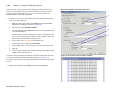
1
ModelSim
®
Advanced Verification and Debugging
Designer
Tutorial
Version 6.0a
Published: October 12, 2004
T-2
This document is for information and instruction purposes. Mentor Graphics reserves the right to make changes in
specifications and other information contained in this publication without prior notice, and the reader should, in all cases,
consult Mentor Graphics to determine whether any changes have been made.
The terms and conditions governing the sale and licensing of Mentor Graphics products are set forth in written agreements
between Mentor Graphics and its customers. No representation or other affirmation of fact contained in this publication
shall be deemed to be a warranty or give rise to any liability of Mentor Graphics whatsoever.
MENTOR GRAPHICS MAKES NO WARRANTY OF ANY KIND WITH REGARD TO THIS MATERIAL
INCLUDING, BUT NOT LIMITED TO, THE IMPLIED WARRANTIES OR MERCHANTABILITY AND FITNESS
FOR A PARTICULAR PURPOSE.
MENTOR GRAPHICS SHALL NOT BE LIABLE FOR ANY INCIDENTAL, INDIRECT, SPECIAL, OR
CONSEQUENTIAL DAMAGES WHATSOEVER (INCLUDING BUT NOT LIMITED TO LOST PROFITS) ARISING
OUT OF OR RELATED TO THIS PUBLICATION OR THE INFORMATION CONTAINED IN IT, EVEN IF MENTOR
GRAPHICS CORPORATION HAS BEEN ADVISED OF THE POSSIBILITY OF SUCH DAMAGES.
RESTRICTED RIGHTS LEGEND 03/97
U.S. Government Restricted Rights. The SOFTWARE and documentation have been developed entirely at private expense
and are commercial computer software provided with restricted rights. Use, duplication or disclosure by the U.S.
Government or a U.S. Government subcontractor is subject to the restrictions set forth in the license agreement provided
with the software pursuant to DFARS 227.7202-3(a) or as set forth in subparagraph (c)(1) and (2) of the Commercial
Computer Software - Restricted Rights clause at FAR 52.227-19, as applicable.
ModelSim Designer Tutorial
T-3
Table of Contents
Introduction . . . . . . . . . . . . . . . . . . . . . . . . . . . . . . . . . . . . . . . . . . . . . . .T-5
Lesson 1 - ModelSim Designer overview . . . . . . . . . . . . . . . . . . . . . . . . .T-9
Lesson 2 - Working with ModelSim Designer . . . . . . . . . . . . . . . . . . . .T-19
Lesson 3 - Creating block diagrams . . . . . . . . . . . . . . . . . . . . . . . . . . . .T-37
Lesson 4 - Creating state diagrams . . . . . . . . . . . . . . . . . . . . . . . . . . . .T-53
Lesson 5 - Viewing simulations in the Wave window . . . . . . . . . . . . . . .T-71
Lesson 6 - Viewing and initializing memories . . . . . . . . . . . . . . . . . . . .T-81
Lesson 7 - Simulating with Code Coverage . . . . . . . . . . . . . . . . . . . . . .T-95
Index . . . . . . . . . . . . . . . . . . . . . . . . . . . . . . . . . . . . . . . . . . . . . . . . . . T-115
ModelSim Designer Tutorial
T-4
ModelSim Designer Tutorial
T-5
Introduction
Topics
The following topics are covered in this chapter:
Assumptions .
.
.
.
.
.
.
.
.
.
.
.
.
.
.
.
.
.
.
.
.
.
.
.
.
T-6
Before you begin . .
Example designs .
.
.
.
.
.
.
.
.
.
.
.
.
.
.
.
.
.
.
.
.
.
.
.
.
.
.
.
.
.
.
.
.
.
.
.
.
.
.
.
.
.
.
.
.
T-8
T-8
ModelSim Designer Tutorial
T-6
Introduction
Assumptions
We assume that you are familiar with the use of your operating system.
We also assume that you have a working knowledge of VHDL and/or Verilog. Although ModelSim is an excellent tool to use
while learning HDL concepts and practices, this document is not written to support that goal.
ModelSim Designer Tutorial
Where to find our documentation
T-7
Where to find our documentation
ModelSim documentation is available from our website at www.model.com/support or in the following formats and locations:
Document
Format
How to get it
ModelSim Installation &
Licensing Guide
paper
shipped with ModelSim
PDF
select Help > Documentation; also available from the Support
page of our web site: www.model.com
ModelSim Quick Guide
(command and feature
quick-reference)
paper
shipped with ModelSim
PDF
select Help > Documentation, also available from the Support
page of our web site: www.model.com
ModelSim Tutorial
PDF, HTML
select Help > Documentation; also available from the Support
page of our web site: www.model.com
ModelSim User’s Manual
PDF, HTML
select Help > Documentation
ModelSim Command
Reference
PDF, HTML
select Help > Documentation
ModelSim GUI & Editor
Reference
PDF, HTML
select Help > Documentation
Command Help
ASCII
type help
Error message help
ASCII
type verror
Tcl Man Pages (Tcl
manual)
HTML
select Help > Tcl Man Pages, or find contents.htm in
\modeltech\docs\tcl_help_html
Technotes
HTML
select Technotes dropdown on www.model.com/support
[command name]
<msgNum>
at the prompt in the Transcript pane
at the Transcript or shell prompt
ModelSim Designer Tutorial
T-8
Introduction
Before you begin
Preparation for some of the lessons leaves certain details up to you. You will decide the best way to create directories, copy files,
and execute programs within your operating system. (When you are operating the simulator within ModelSim’s GUI, the interface
is consistent for all platforms.)
Example designs
ModelSim comes with Verilog and VHDL versions of the designs used in these lessons. This allows you to do the tutorial
regardless of which license type you have. Though we have tried to minimize the differences between the Verilog and VHDL
versions, we could not do so in all cases. In cases where the designs differ (e.g., line numbers or syntax), you will find languagespecific instructions. Follow the instructions that are appropriate for the language that you are using.
ModelSim Designer Tutorial
T-9
Lesson 1 - ModelSim Designer overview
Topics
The following topics are covered in this chapter:
Introduction .
.
.
.
.
.
.
.
.
.
.
.
.
.
.
.
.
.
.
.
.
.
.
.
. T-10
Basic ModelSim Designer flow .
.
.
.
.
.
.
.
.
.
.
.
.
.
.
.
.
.
.
. T-11
Set vendor tools and default language
.
.
.
.
.
.
.
.
.
.
.
.
.
.
.
.
.
. T-12
Create the design . .
Create a project .
Create design units
Create a testbench
.
.
.
.
.
.
.
.
.
.
.
.
.
.
.
.
.
.
.
.
.
.
.
.
.
.
.
.
.
.
.
.
.
.
.
.
.
.
.
.
.
.
.
.
.
.
.
.
.
.
.
.
.
.
.
.
.
.
.
.
.
.
.
.
.
.
.
.
.
.
.
.
.
.
.
.
.
.
.
.
.
.
.
.
.
.
.
.
Simulate the design .
.
.
.
.
.
.
.
.
.
.
.
.
.
.
.
.
.
.
.
.
.
. T-14
Synthesize the design.
.
.
.
.
.
.
.
.
.
.
.
.
.
.
.
.
.
.
.
.
.
. T-15
Place and route the design
.
.
.
.
.
.
.
.
.
.
.
.
.
.
.
.
.
.
.
.
. T-16
Run post place and route simulation .
.
.
.
.
.
.
.
.
.
.
.
.
.
.
.
.
.
. T-17
T-13
T-13
T-13
T-13
ModelSim Designer Tutorial
T-10
Lesson 1 - ModelSim Designer overview
Introduction
ModelSim Designer is a design creation, simulation, and debugging tool for VHDL, Verilog, and mixed-language designs.
This lesson provides a brief overview of the ModelSim Designer environment and the basic Designer flow.
Related reading
ModelSim User’s Manual, Chapter 2 - Getting started with ModelSim Designer
ModelSim Designer Tutorial
(UM-1)
Basic ModelSim Designer flow
T-11
Basic ModelSim Designer flow
The following diagram shows the six basic steps for working with ModelSim Designer.
Set vendor tools and default
language
Create the design
Simulate the design
Synthesize the design
Place and route the
design
Run post place and
route simulation
ModelSim Designer Tutorial
T-12
Lesson 1 - ModelSim Designer overview
Set vendor tools and default language
The first time you start ModelSim Designer, it prompts you to set an FPGA Vendor, Synthesis tool, and default language. It also
scans your system to see if it can find existing vendor tools. If it finds any, it sets the FPGA Vendor and Synthesis tool to match.
Once you click OK, ModelSim compiles the specified vendor libraries. You can compile additional libraries later on by selecting
Tools > FPGA Library Compiler. ModelSim Designer gives you the option of setting different target vendor technologies on a
per design unit basis.
ModelSim Designer Tutorial
Create the design
T-13
Create the design
ModelSim Designer includes graphical and textual editors to facilitate design creation. These editors include:
• Block diagram editor
• State machine editor
• Text editor
• Waveform editor for stimulus creation
Creating a design includes three main steps:
1
Create a project
2
Create design units
3
Create a testbench
Create a project
Projects serve as containers for all the design files and information associated with your design. Projects may include design data,
user data such as project documentation, downstream data for external tools, and compiler and simulation configuration
information.
Create design units
You can use any of the editors to begin building your design or you can import design elements from external libraries.
Create a testbench
You’ll often want to create a testbench to exercise your design. You can write a testbench from scratch using the Source window
or you can create a graphical testbench by using the waveform editor.
ModelSim Designer Tutorial
T-14
Lesson 1 - ModelSim Designer overview
Simulate the design
When you have created all the design units and a testbench, you compile the design and then load the top-level into the simulator.
You can drive the simulation from the Main window or directly from the block diagram or state machine editors.
If you get the results you expect, your next step is typically to synthesize the design. If you don’t get the results you expect, you
can use ModelSim’s suite of debugging tools to troubleshoot and correct the design.
ModelSim Designer Tutorial
Synthesize the design
T-15
Synthesize the design
ModelSim Designer interfaces smoothly with a variety of downstream synthesis tools. ModelSim compiled the necessary vendor
libraries when you first invoked the tool, so in many cases you can just select the top-level of the design, click the synthesis
button...
...configure the synthesis tool...
...and then click OK to invoke the synthesis tool in batch mode.
ModelSim Designer Tutorial
T-16
Lesson 1 - ModelSim Designer overview
Place and route the design
Place and route works similarly to synthesis in ModelSim Designer. Select the top-level of the design, click the Place and Route
icon...
...adjust settings if necessary...
...and then click OK to run place and route.
The post place and route netlist and the SDF file are both linked into the project automatically.
ModelSim Designer Tutorial
Run post place and route simulation
T-17
Run post place and route simulation
With the place and route finished, you can run a gate-level simulation with timing. All of the required files are in place in the
project so just click the simulate icon to load the design. Again, you can use ModelSim’s debugging tools to investigate any
problems.
ModelSim Designer Tutorial
T-18
Lesson 1 - ModelSim Designer overview
ModelSim Designer Tutorial
T-19
Lesson 2 - Working with ModelSim Designer
Topics
The following topics are covered in this lesson:
Introduction . . .
Related reading .
.
.
.
.
.
.
.
.
.
.
.
.
.
.
.
.
.
.
.
.
.
.
.
.
.
.
.
.
.
.
.
.
.
.
.
.
.
.
.
.
.
.
. T-20
. T-20
Starting up Designer .
.
.
.
.
.
.
.
.
.
.
.
.
.
.
.
.
.
.
.
.
.
. T-21
Navigating the ModelSim interface .
.
.
.
.
.
.
.
.
.
.
.
.
.
.
.
.
.
. T-23
Managing designs with the Design tab .
.
.
.
.
.
.
.
.
.
.
.
.
.
.
.
.
. T-27
Simulating the design
.
.
.
.
.
.
.
.
.
.
.
.
.
.
.
.
.
.
. T-30
Creating projects and importing files
.
.
.
.
.
.
.
.
.
.
.
.
.
.
.
.
.
. T-33
Lesson wrap-up .
.
.
.
.
.
.
.
.
.
.
.
.
.
.
.
.
.
. T-35
.
.
.
.
.
.
.
.
ModelSim Designer Tutorial
T-20
Lesson 2 - Working with ModelSim Designer
Introduction
In this lesson we will introduce you to the primary components of the ModelSim
Designer interface. You will do the following:
•
Open an existing project and browse the design in the Workspace Design
tab
•
Open existing block diagrams, state machines, and HDL text files from
the Design tab
•
Load a design with the Start Simulation dialog
•
Add waves to the wave window and run the design
In later lessons you will practice using some of the individual tools such as the
block diagram editor and Dataflow window.
Related reading
ModelSim User’s Manual, Chapter 3 - Projects and design management
ModelSim Designer Tutorial
(UM-23)
Starting up Designer
Starting up Designer
1
T-21
Figure 1: The Tool Set Up dialog
Start ModelSim Designer.
a
Use the ModelSim Designer icon in Windows.
If you see a Welcome window appear, click Close.
2
Specify your vendor tools and default language.
The first time you invoke ModelSim Designer, you are prompted to identify
your vendor tools and which libraries you want to compile (Figure 1).
a
Select your FPGA vendor.
b
Select your Synthesis tool.
c
Select the language.
d
Select the libraries you want to compile. Use your mouse and the <Ctrl>
or <Shift> keys to select from the listed libraries.
2a
2b
2c
At this point ModelSim Designer compiles the selected vendor libraries.
This may take some time.
ModelSim Designer Tutorial
T-22
Lesson 2 - Working with ModelSim Designer
By default ModelSim displays a Welcome dialog upon invocation that is
similar to the one shown in Figure 2.
3
Figure 2: The Welcome dialog
Click Close.
ModelSim Designer requires that you have a project open. Consequently, it will
always open a project upon start-up. The first time you invoke the tool, it will open
the example uart project that ships with the product. In subsequent invocations, it
will re-open whichever project was open when you last exited the tool.
Assuming that you are invoking the tool for the first time or that you have never
opened another project, you should see the uart project in the Design tab (Figure
3). If you don’t see this project, open it by clicking in the Design tab and selecting
File > Open. The project is located at <install_dir>/examples/<language>/
uart.hdp where <language> is VHDL or Verilog (the examples in this section use
the VHDL version).
3
Figure 3: The uart project
ModelSim Designer Tutorial
Navigating the ModelSim interface
Navigating the ModelSim interface
T-23
Figure 4: The ModelSim Designer Main window
The window you are now looking at is called the ModelSim Main window. It is
composed of a number of "panes" and sub-windows that display various types of
information about your design, simulation, or debugging session. You can also
access other tools from the Main window that display in stand-alone windows
(e.g., block diagram editor, Dataflow window, List window).
The following table describes some of the key parts of the Main window.
Window/pane
Description
Workspace
This pane comprises multiple tabs that contain various
sorts of information about the current project or
design. Once a design is loaded, additional tabs will
appear. See "Workspace" (GR-21) in the ModelSim
GUI & Editor Reference for more information.
Transcript
The Transcript pane provides a command-line
interface and serves as an activity log including status
and error messages. See "Transcript" (GR-22) in the
ModelSim GUI & Editor Reference for more
information.
MDI frame
Workspace
Transcript
MDI frame
The Multiple Document Interface (MDI) frame holds
windows for which there can be multiple instances.
These include Source editor windows, Wave
windows, and Memory content windows. See
"Multiple document interface (MDI) frame" (GR-23) in
the ModelSim GUI & Editor Reference for more
information.
ModelSim Designer Tutorial
T-24
Lesson 2 - Working with ModelSim Designer
Here are a few important points to keep in mind about the ModelSim interface:
• Windows/panes can be resized, moved, zoomed, undocked, etc. and the changes
are persistent
Figure 5: Pane control icons
Zoom
Undock
Close
You have a number of options for re-sizing, re-positioning, undocking/
redocking, and generally modifying the physical characteristics of windows
and panes. When you exit ModelSim, the current layout is saved so that it
appears the same the next time you invoke the tool. See "Main window" (GR20) in the ModelSim GUI & Editor Reference for more information.
• Menus are context sensitive
The menu items that are available and how certain menu items behave depend
on which pane or window is active. For example, if the Design tab in the
Workspace is active, and you choose Edit from the menu bar, the Clear
command is disabled. However, if you click in the Transcript pane and
choose Edit, the Clear command is enabled. The active pane is denoted by a
blue title bar.
Let us try a few things.
1
Zoom and undock panes.
a
Click the zoom icon on the Workspace (Figure 5).
The pane fills the entirety of the Main window (Figure 6).
b
Click the unzoom icon the Workspace.
c
Click the undock icon on the Transcript.
The Transcript becomes a stand-alone window.
d
Click the dock icon on the Transcript.
e
Click the close button on the Workspace.
f
Select View > Workspace to re-open the Workspace.
ModelSim Designer Tutorial
Figure 6: Zoomed Workspace pane
Unzoom
Navigating the ModelSim interface
2
Move and resize panes.
a
Hover your mouse pointer on top of the Transcript title bar so it becomes
a four-headed arrow.
b
Click and drag the Transcript up and to the right until you see a gray
outline on the right-hand side of the MDI frame.
T-25
Figure 7: Panes rearranged in the Main window
When you let go of the mouse button, the Transcript is moved and the
MDI frame and Workspace panes shift to the left (Figure 7).
c
Select Window > Initial Layout.
The layout returns to its original setting.
Important: Moving panes can get confusing, and you may not always
obtain the results you expect. The general rule is as follows: any pane
can be split vertically or horizontally, multiple times. The best plan is
to play around a bit, watch the gray outlines, and see what happens
when you drop panes in various places.
You won’t have to do this very often. Once you have a layout you like,
it will be saved when you exit ModelSim.
Selecting Window > Initial Layout is the easiest way to rectify an
undesired layout.
d
Hover your mouse pointer on the border between two panes so it
becomes a double-headed arrow.
e
Click-and-drag left and right or up and down to resize the pane.
f
Select Window > Initial Layout.
ModelSim Designer Tutorial
T-26
3
Lesson 2 - Working with ModelSim Designer
View stand-alone windows.
a
Select View > Debug Windows > List.
The List window displays results from a simulation run in tabular format.
See "List window" (GR-113) in the ModelSim GUI & Editor Reference for
more information.
b
Select View > Debug Windows > Dataflow.
The Dataflow window allows you to explore the physical connectivity of
your design. See "Dataflow window" (GR-98) in the ModelSim GUI &
Editor Reference for more information.
Note: Many of the options listed under Debug Windows display only
when a simulation is loaded.
c
4
Close the List and Dataflow windows.
Observe context sensitivity of menu commands.
a
Click anywhere in the Design tab of the Workspace.
b
Select the Edit menu and notice that the Clear command is disabled.
c
Click in the Transcript and select Edit > Clear.
This command applies to the Transcript pane but not the Workspace
pane.
d
Click back in the Design tab of the Workspace and select File > Open.
Notice that the Open dialog filters to show project files.
e
Now click in the MDI frame and select File > Open.
Notice that the Open dialog filters to show HDL file types instead.
ModelSim Designer Tutorial
Managing designs with the Design tab
Managing designs with the Design tab
T-27
Figure 8: Different views of uart_top
The Design tab serves as the central access point for all objects in your design.
This includes design units and their different views (graphical, textual),
supporting design data (SDF files, etc.), and other related files (e.g.,
documentation, scripts, etc.).
The Design tab is organized hierarchically. When you expand items, you see
different views of the design unit.
1b
The icons in the Design tab communicate a variety of information. For more
details see "Design tab icon descriptions" (UM-33) in the ModelSim User’s Manual.
1
Open different views.
a
Expand the uart_top component so you can see all of the views (Figure
8).
b
Double-click uart_top/struct.bd to open a block diagram view (Figure 9).
c
From the block diagram editor, select File > Close Window.
Figure 9: A block diagram view of uart_top
ModelSim Designer Tutorial
T-28
Lesson 2 - Working with ModelSim Designer
d
Double-click uart_top/symbol.sb to open a symbol and interface view
(Figure 10).
e
Click the Interface tab.
f
Select File > Close Window.
Figure 10: A symbol view of uart_top
If ModelSim prompts you to save changes, click No.
g
Double-click uart_top_struct.vhd (or uart_top_struct.v if you are using
the Verilog version of the design) to open the HDL generated from the
block diagram (Figure 11). The file opens in a Source editor in the MDI
frame of the Main window.
1e
Figure 11: An HDL view of uart_top
ModelSim Designer Tutorial
Managing designs with the Design tab
2
Figure 12: Side Data for the UART design
View Side Data pane.
a
T-29
Right-click in the Design tab and select Show Side Data (Figure 12).
Increase the size of the Workspace if necessary.
The Side Data pane includes three categories of information:
Side Data category
Description
Design Data
non-HDL files that are required for the
design (e.g., substitute synthesized design
unit, SDF files, etc.)
User Data
any design-related files that you want to
collect in one spot (e.g., scripts, design
documentation, etc.)
Downstream Data
files that are required for specific
downstream tools
ModelSim Designer Tutorial
T-30
Lesson 2 - Working with ModelSim Designer
Simulating the design
To simulate the sample UART design, we will load the top level which is uart_tb.
1
Load the design.
a
Right-click uart_tb and select Flow > Simulate (Figure 13).
ModelSim automatically compiles any source files that haven’t already
been compiled or that have changed since the last simulation. Once all
files are compiled, ModelSim opens the Start Simulation dialog.
The Start Simulation dialog already has the correct design unit specified.
The dialog appears in case there are other settings you need to modify to
run the simulation. See "Start Simulation dialog" (GR-58) in the
ModelSim GUI & Editor Reference for more details on this dialog.
b
Click OK.
ModelSim Designer Tutorial
Figure 13: Simulating the top level of the design
Simulating the design
2
Add items to a Wave window.
a
T-31
Figure 14: Adding objects from the current region to a Wave window
In the Sim tab of the Workspace, right-click uart_tb and select Add >
Add to Wave (Figure 14).
This adds objects from the current region to a Wave window that is
displayed in the Main window MDI frame (Figure 15).
Figure 15: A Wave window in the MDI frame
ModelSim Designer Tutorial
T-32
3
Lesson 2 - Working with ModelSim Designer
Run the simulation
a
Click in the Transcript pane.
b
Type run 1000 and press enter.
Waves draw in the Wave window (Figure 16).
You will explore additional features of the Wave window in a later
lesson.
4
Quit the simulation.
a
Select Simulate > End Simulation. Click Yes.
ModelSim Designer Tutorial
Figure 16: Waveforms in the Wave window
Creating projects and importing files
Creating projects and importing files
T-33
Figure 17: Creating a new project
In this exercise you will create a new project and then import some existing HDL
files.
1
Create the new project.
a
Select File > New > Project.
b
Enter the following in the New Project dialog (Figure 17):
c
•
Type example for the Project Name.
•
Enter any suitable path.
•
Type work for the Default Library.
Click OK.
The Design tab in the Workspace shows the new project and library.
Figure 18: HDL Import Wizard
2
Import example files.
a
Select File > Import > HDL.
This starts the HDL Import Wizard.
b
Make sure Specify HDL files is selected in the first dialog and click
Next.
c
Click the Browse button and navigate to <install_dir>/examples>
(Figure 18).
VHDL: Select counter.vhd and tcounter.vhd and click Add.
Verilog: Select counter.v and tcounter.v and click Add.
d
Click Next.
e
Select work under the Libraries list and click Next.
f
Click Finish.
ModelSim Designer Tutorial
T-34
Lesson 2 - Working with ModelSim Designer
A counter and its testbench appear in the Design tab (Figure 19).
ModelSim Designer Tutorial
Figure 19: Counter and testbench imported into the project
Lesson wrap-up
T-35
Lesson wrap-up
This concludes this lesson. At this point you are ready to explore the design editor
and debugging tools that comprise ModelSim Designer.
Design editor lessons
Lesson 3 - Creating block diagrams
Lesson 4 - Creating state diagrams
Debugging tool lessons
Lesson 5 - Viewing simulations in the Wave window
Lesson 6 - Viewing and initializing memories
Lesson 7 - Simulating with Code Coverage
ModelSim Designer Tutorial
T-36
Lesson 2 - Working with ModelSim Designer
ModelSim Designer Tutorial
T-37
Lesson 3 - Creating block diagrams
Topics
The following topics are covered in this lesson:
Introduction . . .
Related reading .
.
.
.
.
.
.
.
.
.
.
.
.
.
.
.
.
.
.
.
.
.
.
.
.
.
.
.
.
.
.
.
.
.
.
.
.
.
.
.
.
.
.
. T-38
. T-38
Creating a new project
.
.
.
.
.
.
.
.
.
.
.
.
.
.
.
.
.
.
.
.
.
. T-39
Creating a new block diagram . . . .
Adding blocks . . . . . . .
Adding ports and signals . . . .
Adding a bundle and a global connector
Saving the block diagram . . . .
.
.
.
.
.
.
.
.
.
.
.
.
.
.
.
.
.
.
.
.
.
.
.
.
.
.
.
.
.
.
.
.
.
.
.
.
.
.
.
.
.
.
.
.
.
.
.
.
.
.
.
.
.
.
.
.
.
.
.
.
.
.
.
.
.
.
.
.
.
.
.
.
.
.
.
.
.
.
.
.
Editing block and signal names .
T-40
T-41
T-42
T-43
T-44
.
.
.
.
.
.
.
.
.
.
.
.
.
.
.
.
.
.
. T-45
Adding an embedded HDL text view
.
.
.
.
.
.
.
.
.
.
.
.
.
.
.
.
.
. T-48
Adding a panel
.
.
.
.
.
.
.
.
.
.
.
.
.
.
.
.
.
.
.
.
.
.
.
. T-50
Lesson wrap-up .
.
.
.
.
.
.
.
.
.
.
.
.
.
.
.
.
.
.
.
.
.
.
. T-51
ModelSim Designer Tutorial
T-38
Lesson 3 - Creating block diagrams
Introduction
In this lesson you will create part of a simple timer using block diagrams,
embedded text views, and state machines.
Related reading
ModelSim Graphical Interface and Editor Reference – Chapter 2 - Introduction
to graphical editors and Chapter 4 - Block diagram editor.
ModelSim Designer Tutorial
Figure 20: A completed block diagram
Creating a new project
Creating a new project
T-39
Figure 21: Creating the GraphTutor project
For this lesson you will create a new project.
1
Start ModelSim if necessary.
a
Use the ModelSim icon in Windows.
If the Welcome to ModelSim dialog appears, click Close.
2
Create a new project.
a
Select File > New > Project.
b
In the New Project dialog, type GraphTutor for the Project Name and
Default Library (Figure 21).
c
Click OK.
The Design tab in the Workspace pane show the new project and library
(Figure 22).
Figure 22: The new project and library in the Workspace pane
ModelSim Designer Tutorial
T-40
Lesson 3 - Creating block diagrams
Creating a new block diagram
1
Figure 23: The File Creation Wizard
Use the File Creation wizard to create a new block diagram.
a
In the Workspace under the GraphTutor library, double-click the New
icon.
1c
This opens the File Creation Wizard (Figure 23).
b
Select the appropriate language if necessary.
c
Double-click Block Diagram under Graphical Views.
This opens a new block diagram editor window (Figure 24).
d
Click the View All button
to view the entire diagram.
The block diagram is a blank sheet except for a background grid, a
package list (with the standard IEEE libraries std_logic_1164 and
std_logic_arith) and empty text fields with labels for Declarations, Ports
and Diagram Signals.
The diagram also shows page boundaries for the default printer and a
copy of the default title block.
1b
Figure 24: A new block diagram
1d
2
Edit the title block.
A title block is automatically added to all new diagrams if the Add Title
Blocks in new diagrams option is set in your diagram preferences.
The title block incorporates internal variables which automatically enter the
current project name, your login name, and the current date. Internal variables
are also used to enter the logical pathname for the design. This path is initially
shown as <TBD>/<TBD>/<TBD> but the internal variables are converted to
show the library, design unit and view name when you save the diagram.
a
Click twice on <company name> in the title block to display a popup edit
box and replace the default text by the name of your company.
b
Click twice on <enter diagram title here> and enter a title such as "Top
Level Timer Block Diagram".
c
Click twice on <enter comments here> and enter "Created by <your
name> on <date>".
d
With the title block selected, select File > Save Title Block and click Yes
to confirm.
ModelSim Designer Tutorial
Creating a new block diagram
Adding blocks
1
T-41
Figure 25: Two blocks added to the diagram
Use the
button (or select Add > Block) to add two blocks on the diagram
(Figure 25).
Notice that the blocks are added with the default library <library>, the
default name <block> and unique instance names (U_0 and U_1).
Note: The Add Block command normally auto-repeats until you select
another command or terminate the repeating command by using the
right mouse button or <Esc> key. However, you can change the
behavior of the toolbar buttons by setting the Activate once only
preference in the General tab of the Main Settings dialog box.
You can also use the <Ctrl> key with any toolbar button to toggle the
repeat mode. For example, when Remain active is set, <Ctrl> + the Add
Block button adds a single block.
2
Use the
button to add two embedded blocks on your block diagram
(Figure 26).
Figure 26: Two embedded blocks added to the diagram
Notice that the embedded blocks are added with unique default names (eb1
and eb2) and numbers (1 and 2).
The view describing a block must be saved as a uniquely named design unit
in a library directory. However, the view describing an embedded block is
saved as part of the parent block diagram and does not impose hierarchy when
HDL is generated for your design. The name of an embedded block must be
unique on the diagram and is used as a label in the generated HDL.
The blocks (U_0 and U_1) will be used to define a child state machine and
block diagram views. The embedded blocks (eb1 and eb2) will be defined by
concurrent assignment statements on the top level block diagram.
ModelSim Designer Tutorial
T-42
Lesson 3 - Creating block diagrams
Adding ports and signals
You can use the buttons shown at the right to add signal and bus nets on a block
diagram (Figure 27).
Signals or buses can be added between any existing connectable items on the
diagram or left unconnected by double-clicking to terminate the net with an open
net connector. However, you can use the pulldown on the buttons to change the
default setting and terminate with a default port or ripper. Notice that the toolbar
button changes to show the current setting.
When the
or
button is selected, a port is automatically added at an
unconnected source or destination end point. When the
button is selected,
a ripper is used if the end point is over an existing bus or bundle.
1
Add several ports and signals.
a
Choose Signal with Port and use the
button to connect three
signals originating from the block on the left (instance U_0 in the picture)
to the block on the right (instance U_1) and one signal returning from
U_1 to U_0.
The signals are added with unique names (sig0, sig1, sig2 and sig3) and
the default type std_logic. Notice how the full declarations for these
diagram signals are automatically added to the list of Declarations on the
diagram.
Note: Allow one or more grid lines between each port or signal.
You can resize objects by selecting a block or embedded block and
dragging one of its resize handles. If necessary, you can drag text
elements such as the signal name using the left mouse button.
b
Add a signal from block U_0 to the embedded block eb2 and another
signal from a point on sig2 terminating on the embedded block eb2.
c
Add a signal from the embedded block eb2 terminating in space on the
right side of your diagram. Notice that an output port is added when you
double-click at the end of the last signal and its declaration is added to
the list of ports on the diagram.
d
Choose Bus with Port and use the
button to add a bus from a
source on the left side of your diagram with its destination on the upper
ModelSim Designer Tutorial
Figure 27: Toolbar buttons for adding signals and ports
Add a signal
Add a signal with a port
Add a bus
Add a bus with a port
Add a bus with a ripper
Creating a new block diagram
embedded block eb1. A default input port is automatically created at the
beginning of the bus.
e
Add another bus starting from this bus and terminating on instance U_0.
Notice how both bus segments have the same default name dbus0. The
full declaration showing the default bus type and bounds
std_logic_vector(15 DOWNTO 0) is added to the list of ports.
f
Add a bus (dbus1) from eb1 to U_1. This internal diagram signal is
shown with the default bounds (15:0) shown (in abbreviated format) on
the net.
g
Then add two buses (dbus2 and dbus3) from U_1 terminated with default
output ports on the right of the diagram.
T-43
Figure 28: The block diagram with ports and signals
Your diagram should look similar to the one shown in Figure 28.
Adding a bundle and a global connector
1
Figure 29: A bundle and a global connector
Add the bundle.
a
Use the
button to add three signals on the left side of your
diagram. Notice that a default input port is created at the source of each
signal but a dangling net connector is drawn when you double-click at the
end of each signal.
b
Select the three signals (by dragging a selection box around them with
the mouse) and use the
button to connect a bundle containing
these signals to block instance U_0 as shown in Figure 29.
Notice that the bundle has the default name bundle0 and the three selected
signals are automatically included in the bundle with their names listed under
the bundle name.
2
Add the global connector.
a
Use the
bundle.
button to add a global connector on your diagram below the
b
Use the
button to add a signal between the global connector and
a default input port. This will be a clock signal which is implicitly
connected to every block on the diagram.
ModelSim Designer Tutorial
T-44
Lesson 3 - Creating block diagrams
Saving the block diagram
Figure 30: Saving the block diagram
Notice the asterisk (*) character in the header of the block diagram editor window.
This indicates that the diagram has been edited since it was last saved.
1
Save the diagram.
a
Click the
button.
The Save As dialog box allows you to choose from the currently mapped
libraries and specify the design unit and design unit view names (Figure
30).
b
Select GraphTutor under Library.
c
Type Timer for the Design Unit name.
d
Click OK.
The view name and file extension when you save graphical diagrams defaults
as follows:
struct.bd
block diagram
fsm.sm
state diagram
symbol.sb
symbol
If you omit the suffix, it is added automatically.
The default leaf names can be changed by setting preferences. However, you
should not change the extension (.bd, .sm, .sb) or the design data file will not
be recognized and cannot be reopened.
2
View the saved design unit.
a
Switch to the Main window and view the Design tab of the Workspace.
b
Expand the Timer component.
The Timer component has two views–the block diagram view and a
symbol view (Figure 31). Symbol views are created automatically when
you save a block diagram.
ModelSim Designer Tutorial
Figure 31: The Timer component and views in the Design tab
Editing block and signal names
Editing block and signal names
T-45
Figure 32: Editing block and symbol names directly on the diagram
You now have a completed top-level block diagram for the Timer design.
However, the blocks and signals have default names.
1
Edit block names directly on the diagram.
a
Click on the text <block> in the lower block on the left (instance U_0 in
the picture) and notice the small handles which indicate that the text
object is selected. Click again and notice that the text is now highlighted
and can be directly overwritten.
If you click again, the cursor changes to an I-beam which allows you to
move the cursor in the text and edit individual characters. Enter the new
name Control and click outside the text to complete the edit.
b
2
Repeat this procedure to change the name of block instance U_1 to
Counter, embedded block eb1 to DtoB, and embedded block eb2 to OR1
(Figure 32).
Figure 33: The Object Properties dialog
Edit signal names via a dialog.
Direct text editing can also be used to edit the signal and bus names.
Alternatively, you can use a dialog box that allows you to edit the properties
for a selected object. By default, edits to signal and bus nets are applied only
to the connected nets but you can choose to apply the changes to the entire
diagram or to propagate changes to all occurrences of the net in the hierarchy
of the design.
a
Select Diagram > Signals > Scope for Changes > Entire Net in
Diagram.
b
Select Edit > Object Properties.
Notice that the port declarations are listed at the top of the dialog box and
the other internal diagram signals at the bottom (Figure 33). Input ports
are listed before the output ports, otherwise the declarations are listed in
alphanumeric order.
You can choose one or more existing declarations in the dialog box and
enter new values for any of the declaration fields. For example, click
dbus1, dbus2 and dbus3 while holding the <Ctrl> key, then enter a new
index constraint with bounds 3 DOWNTO 0 (3:0 for Vector Bounds in
Verilog) to update all three buses while all other fields remain AS_IS.
ModelSim Designer Tutorial
T-46
c
Lesson 3 - Creating block diagrams
Click Apply to accept the changes.
Notice that all occurrences on the diagram are updated including the
declarations list, signals, buses, and bundle contents and that the lists of
port and signal declarations are sorted alphanumerically when the
changes are applied to the diagram.
d
Use the dialog box to update the port and signal declarations as shown in
the following tables. For Verilog designs, use a type of wire for all ports
and signals:
Ports:
Old Name
New Name
Type
Constraint
Bounds
dbus0
sig6
sig7
sig8
sig9
dbus2
dbus3
sig5
d
start
stop
reset
clk
low
high
alarm
std_logic_vector
std_logic
std_logic
std_logic
std_logic
std_logic_vector
std_logic_vector
std_logic
index
(none)
(none)
(none)
(none)
index
index
(none)
9 DOWNTO 0
(none)
(none)
(none)
(none)
3 DOWNTO 0
3 DOWNTO 0
(none)
Old Name
New Name
Type
Constraint
Bounds
dbus1
sig0
sig1
sig2
sig3
sig4
dat_in
clear
load
hold
zero
beep
std_logic_vector
std_logic
std_logic
std_logic
std_logic
std_logic
index
(none)
(none)
(none)
(none)
(none)
3 DOWNTO 0
(none)
(none)
(none)
(none)
(none)
Diagram Signals:
All occurrences of each signal name (including the bundle contents)
should be automatically updated on the diagram when you confirm the
dialog box. If any nets are not updated, check that you have set the scope
for changes to Entire Net in Diagram as described on the previous page.
ModelSim Designer Tutorial
Editing block and signal names
e
Select the bundle name and use direct text editing or the Bundles tab of
the Object Properties dialog box to change the bundle name to
control_bundle.
T-47
Figure 34: Block diagram with updated names
Your block diagram should look similar to the one shown in Figure 34.
3
Save the diagram.
a
Click the
button.
You have previously saved the diagram so you are not prompted for
library and design unit names. However, you have changed the signal
names connected to input and output ports and the diagram will be
inconsistent with the symbol that was automatically created by the
previous save. You are prompted whether to update the symbol.
b
Click Yes to confirm the save.
You are prompted whether to update instances of the component where
used. For this tutorial, the Timer is a newly created component and is not
used elsewhere.
c
Click No.
ModelSim Designer Tutorial
T-48
Lesson 3 - Creating block diagrams
Adding an embedded HDL text view
Figure 35: The Create Embedded View dialog
In this section you will enter HDL code to define the functionality of the OR1
block on the diagram.
1
Open a new view for the OR1 block.
a
Right-click the OR1 block and select Open > New View (Figure 35).
b
Leave the type of view set to Text and then click OK.
An embedded HDL text view containing default text is displayed on the
block diagram adjacent to the embedded block.
2
Modify the HDL code.
a
Select the text, re-display the Object Properties dialog box if necessary
(using the
button), and choose the Text tab.
b
Check Resize to fit text.
c
Modify the VHDL code so it reads as follows (Figure 36):
-- OR1 2
alarm <= hold OR beep;
If you are working in Verilog, the code will look like this:
// OR1 2
assign alarm = hold | beep;
d
Click OK.
The modified HDL text is checked for syntax errors and applied to the
diagram.
ModelSim Designer Tutorial
Figure 36: Adding VHDL code in the Object Properties dialog
Adding an embedded HDL text view
3
Modify the block shape.
T-49
Figure 37: The modified OR block
The functional blocks on the diagram are shown by default as simple
rectangular shapes. However, it is sometimes useful to use logic notation
when a block has a specific logical function. For example, in this block
diagram, the OR1 embedded block represents a logical OR function.
a
Right-click the OR1 block and select Shape > Autoshapes.
b
Select Or in the dialog and click OK.
c
Right-click the OR1 block and select Object Properties.
d
On the Embedded Blocks tab, uncheck Show Ports when connected to
hide the port arrow heads.
e
Click OK.
The OR1 embedded block should now look similar to the one shown in
Figure 37.
ModelSim Designer Tutorial
T-50
Lesson 3 - Creating block diagrams
Adding a panel
A panel can be useful to outline areas of a diagram. For example, you can use a
panel to outline a view used for simulation or animation.
1
Click the
button
2
Click and drag a panel that encloses the graphical objects on your diagram.
The panel is added with the default name Panel0.
3
Click the
button to save your work.
Your block diagram should look similar to the one shown in Figure 38.
ModelSim Designer Tutorial
Figure 38: The updated block diagram
Lesson wrap-up
T-51
Lesson wrap-up
This concludes this lesson. In the next lesson, you will create a state diagram to
define the Control block.
ModelSim Designer Tutorial
T-52
Lesson 3 - Creating block diagrams
ModelSim Designer Tutorial
T-53
Lesson 4 - Creating state diagrams
Topics
The following topics are covered in this lesson:
Introduction . . .
Related reading .
.
.
.
.
.
.
.
.
.
.
.
.
.
.
.
.
.
.
.
.
.
.
.
.
.
.
.
.
.
.
.
.
.
.
.
.
.
.
. T-54
. T-54
Creating a state machine . . .
Adding states and transitions
.
.
.
.
.
.
.
.
.
.
.
.
.
.
.
.
.
.
.
.
.
.
.
.
.
.
.
.
.
.
.
.
.
.
.
.
. T-55
. T-56
Editing the states and transitions .
Editing the transitions . .
.
.
.
.
.
.
.
.
.
.
.
.
.
.
.
.
.
.
.
.
.
.
.
.
.
.
.
.
.
.
.
.
.
.
.
.
. T-58
. T-60
Creating a hierarchical state machine
.
.
.
.
.
.
.
.
.
.
.
.
.
.
.
.
.
. T-62
Editing state machine properties .
.
.
.
.
.
.
.
.
.
.
.
.
.
.
.
.
.
.
. T-66
Simulate the control block
.
.
.
.
.
.
.
.
.
.
.
.
.
.
.
.
.
.
.
.
. T-69
Lesson wrap-up .
.
.
.
.
.
.
.
.
.
.
.
.
.
.
.
.
.
.
.
.
. T-70
.
.
.
.
.
.
ModelSim Designer Tutorial
T-54
Lesson 4 - Creating state diagrams
Introduction
In this lesson you will create a graphical state machine to describe the Control
block in the block diagram you created in the last lesson. You must complete
Chapter Lesson 3 - Creating block diagrams to proceed with this lesson.
Related reading
ModelSim Graphical Interface and Editor Reference – Chapter 2 - Introduction
to graphical editors, Chapter 7 - State machines, and Chapter 8 - State diagram
editor
ModelSim Designer Tutorial
Creating a state machine
Creating a state machine
T-55
Figure 39: The Open Down Create New View dialog
If you just finished the previous lesson, you should already have the block diagram
open. If not, open the GraphTutor project if necessary and open the Timer block
diagram by double-clicking it in the Design tab of the Workspace.
1
Use the Open Down wizard to create a new state diagram.
a
Right-click the Control block and select Open As > New View.
This opens the Open Down Create New View wizard (Figure 39).
b
Select State Diagram and click Next.
The library and design unit fields are dimmed because they are copied
automatically from the library and design unit of the parent diagram. The
view name defaults to fsm.sm for a state machine (Figure 40).
c
Click Finish.
A new state diagram GraphTutor/Control/fsm [csm] is created as a child view
of the Control block.
Figure 40: Second page of the wizard
Note that a default state machine name csm is appended to the design unit and
view names in the diagram title. Do not change this name.
ModelSim Designer Tutorial
T-56
Lesson 4 - Creating state diagrams
The state diagram is a blank sheet with page boundaries set for the default printer
(Figure 41).
Figure 41: The blank child state diagram
If you are working with VHDL, the diagram includes text objects for the default
VHDL package list and labels for global actions, concurrent statements,
architecture declarations, signals status, process declarations and state register
statements.
If you are working with Verilog, the diagram includes text objects for the default
compiler directives list and labels for global actions, concurrent statements,
module declarations, signals status and state register statements.
Adding states and transitions
1
Click the
button and add five states on your state diagram. The states are
added with default names s0, s1, s2, s3 and s4.
Notice that the first state you add is assumed to be the start state and is drawn
in green with a double outline. The other states are drawn in cyan with a single
outline.
2
Click the
42.
button to add transitions between the states as shown in Figure
The transitions are added with default conditions which will be edited later in
this tutorial.
Notice that when you add more than one transition leaving a state, the
transition priority is indicated by a priority number associated with the
transition arc. The priorities are initially assigned in the order that you add the
transitions but can be re-assigned later if necessary.
If you add a transition in the wrong direction, you can easily change its
direction by selecting Diagram > Reverse Direction.
Note that a popup description (known as an object tip) is displayed when the
arrow or hand cursor is stationary over an object. In particular, when the
cursor is over a transition, the source state and the destination state are named
even if the states are outside the current window.
ModelSim Designer Tutorial
Figure 42: New states and transitions
Creating a state machine
3
Click the
button to save the state diagram.
4
Switch to the Design tab in the Workspace.
T-57
Figure 43: The Design tab showing the Control block and state machine view
The Design tab was updated to display the Control design unit.
The Control design unit is shown as a block in the Design tab because its
interface is defined by the connections on its parent block diagram. The Timer
design unit is shown as a component because it has no parent block diagram
and its interface is defined by a symbol.
If you expand the Control design unit, you will see that it contains a State
Diagram view (Figure 43).
ModelSim Designer Tutorial
T-58
Lesson 4 - Creating state diagrams
Editing the states and transitions
1
Edit the state names and actions.
a
Switch back to the State Diagram.
b
Select the start state (s0 in Figure 42 on page page T-56) and click the
button to display the States tab of the State Machine Object
Properties dialog box (Figure 44).
The States tab allows you to enter a name and actions text for one or more
selected states on a state diagram. You can also change the visibility of
state actions and change the state to a start state or a hierarchical state
(when a single state is selected).
ModelSim Designer Tutorial
Figure 44: The Object Properties dialog for states
Editing the states and transitions
2
Edit the remaining state names and actions.
Use the dialog and the table of state names and actions at the right to edit the
states on the diagram.
State names and actions for VHDL
Old Name
New Name
Style
Actions
The Expression Builder dialog box is automatically displayed when you start
to enter the actions. The expression builder can be used to choose from lists
of the available port or local signal names, operators, and example values.
s0
flush
IF
hold<='1';
clear<='1';
beep<='0';
The Expression Builder dialog box can be explicitly displayed at any time by
selecting Edit > Expression Builder.
s1
count
IF
(no actions)
The syntax for state actions is automatically checked and any errors reported
on entry. VHDL and Verilog statements must be terminated by a semicolon
(;) character. Line breaks and spaces can be used for clarity and will be
preserved on the diagram.
s2
getkey
IF
hold<='1';
s3
load_t
IF
hold<='1';
s4
load_u
IF
hold<='1';
load<='1';
You can also edit the state name or actions by direct text editing on the
diagram or copy a state and paste its state actions into another state by
choosing Paste Special > Paste State Actions from the popup menu.
T-59
State names and actions for Verilog
Old Name
New Name
Style
Actions
s0
flush
IF
hold = 1;
clear = 1;
load = 0;
s1
count
IF
(no actions)
s2
getkey
IF
hold = 1;
clear = 0;
load = 0;
s3
load_t
IF
hold = 1;
clear = 0;
load = 0;
s4
load_u
IF
hold = 1;
clear = 0;
load = 1;
ModelSim Designer Tutorial
T-60
Lesson 4 - Creating state diagrams
Editing the transitions
1
2
Edit the flush state transitions.
a
Select the two transitions entering the state flush by dragging the cursor
across them.
b
Click the
button to display the Transitions tab of the State Machine
Object Properties dialog box.
c
Replace the default condition by the new condition stop='1' (stop in
Verilog) and click Apply to add this condition to both of the selected
transitions.
Edit the rest of the transitions.
Use the tables at the right to edit the remaining transitions. Use the table that
matches the language you are using.
Note: The NOUGHTS text string is the name of a constant which will
be declared as a state machine property later in this tutorial.
3
Click the
button to save the state diagram.
ModelSim Designer Tutorial
Transitions for VHDL
Origin
Destination
Priority
Condition
count
flush
1
stop='1'
getkey
flush
3
stop='1'
getkey
count
1
start='1'
getkey
load_u
2
d/=NOUGHTS
flush
load_u
1
d/=NOUGHTS
load_u
load_t
1
(none)
load_t
getkey
1
d/=NOUGHTS
Transitions for Verilog
Origin
Destination
Priority
Condition
count
flush
1
stop
getkey
flush
3
stop
getkey
count
1
start
getkey
load_u
2
d!=NOUGHTS
flush
load_u
1
d!=NOUGHTS
load_u
load_t
1
(none)
load_t
getkey
1
d!=NOUGHTS
Editing the states and transitions
T-61
Your state machine should now look similar to the one shown below.
ModelSim Designer Tutorial
T-62
Lesson 4 - Creating state diagrams
Creating a hierarchical state machine
Figure 45: The new child state diagram
In this exercise we will create a child state machine that defines the functionality
of the count state.
1
Create the child state diagram.
a
Select the count state and select Diagram > Change To > Hierarchical
State
The count state is redrawn as a hierarchical state with a triple outline and
darker fill color.
b
Double-click the count hierarchical state to create the new hierarchical
child state diagram.
A new child state diagram is opened as a tabbed window initialized with
a default state s0 connected to an entry point and exit point by transitions
with default conditions (Figure 45).
Notice that the name of the hierarchical state count is included in the
window title: GraphTutor/Control/fsm [csm/count]. This convention
shows that the child diagram is a partial view of the parent diagram.
2
Add states and transitions to the diagram.
a
Select the exit point and select Diagram > Change to > State.
b
While the new state is selected, drag with the right mouse button and
release the mouse button with the ghosted state to the left and below the
first state. Use the Copy Here option from the popup menu to make a
copy of the state at the cursor position.
c
Repeat this procedure to add two more states on the diagram. This
method for adding objects can be useful when you want to add an object
with the same or similar properties and attributes to an existing object.
d
Use the
button to add a new exit point and the
button to connect
transitions between the states as shown in Figure 46.
Note: You can add route points by clicking at several points
between states to create a smooth arc as shown in the picture
between states s2 and s3.
ModelSim Designer Tutorial
Figure 46: States and transitions added to the diagram
Creating a hierarchical state machine
3
Edit the states.
a
Use the State tab of the Object Properties dialog and the tables at the right
to edit the states.
T-63
State names and actions for VHDL
Old Name
New Name
Style
Actions
s0
standby
IF
hold<='1';
s1
alarm
IF
hold<='1';
clear<='1';
beep<='1';
s2
counting
IF
(none)
s3
suspended
IF
hold<='1';
s4
end_count
IF
hold<='1';
clear<='1';
State names and actions for Verilog
Old Name
New Name
Style
Actions
s0
standby
IF
hold = 1;
clear = 0;
load = 0;
s1
alarm
IF
hold = 1;
clear = 1;
load = 0;
beep = 1;
s2
counting
IF
hold = 0;
clear = 0;
load = 0;
s3
suspended
IF
hold = 1;
clear = 0;
load = 0;
s4
end_count
IF
hold = 1;
clear = 1;
load = 0;
ModelSim Designer Tutorial
T-64
4
Lesson 4 - Creating state diagrams
Edit the transitions.
a
Use the Transitions tab of the Object Properties dialog and the tables at
the right to edit the transitions.
Transitions for VHDL
Origin State
Destination State
Priority
Condition
Actions
suspended
counting
1
stop='0'
(none)
counting
suspended
2
stop='1'
(none)
counting
alarm
1
zero='1'
(none)
standby
counting
2
start='1'
(none)
standby
alarm
1
zero='1'
(none)
alarm
end_count
1
stop='1'
(none)
entry point
standby
1
(none)
(none)
end_count
exit point
1
(none)
(none)
Transitions for Verilog
ModelSim Designer Tutorial
Origin State
Destination State
Priority
Condition
Actions
suspended
counting
1
~stop
(none)
counting
suspended
2
stop
(none)
counting
alarm
1
zero
(none)
standby
counting
2
start
(none)
standby
alarm
1
zero
(none)
alarm
end_count
1
stop
(none)
entry point
standby
1
(none)
(none)
end_count
exit point
1
(none)
(none)
Creating a hierarchical state machine
T-65
Your diagram should look similar to the one shown below.
5
Click the
button to save the state diagram.
Although it is displayed in a separate tab, a child hierarchical diagram is a
partial view of a state machine and the parent and child diagrams are saved as
a single design unit view (GraphTutor/Control/fsm.sm).
ModelSim Designer Tutorial
T-66
Lesson 4 - Creating state diagrams
Editing state machine properties
There are a number of properties associated with a state machine that can be edited
using the State Machine Properties dialog box.
1
Hide unneeded labels.
a
Click the csm tab to move back to the parent state machine.
b
Select Diagram > State Machine Properties.
This dialog is described in detail under "Setting state machine properties"
in the ModelSim Designer GUI & Interface Reference.
(GR-472)
c
Select the Statement Blocks tab and uncheck Visible for Global
Actions, Concurrent Statements, and State Register Statements.
There are no global actions, concurrent statements, or state register
statements required in this design, so you are hiding the labels for these
objects on the state diagram.
d
If you are using VHDL, select the Process Declarations tab and uncheck
Visible.
There are no process declarations required in this design.
2
Define the NOUGHTS constant.
a
VHDL: Select the Architecture Declarations tab and enter the
following declaration for the 10-bit constant NOUGHTS in the freeformat entry box:
Constant NOUGHTS : std_logic_vector := "0000000000";
Verilog: Select the Module Declarations tab and enter the following
declaration for the 10-bit constant NOUGHTS in the free-format entry
box:
parameter NOUGHTS = 10’b0;
3
Edit signal status.
b
Select the Signals Status tab.
c
Change signal beep status to Registered (Figure 47).
Notice that the Reset value field is automatically updated to ‘0’.
ModelSim Designer Tutorial
Figure 47: Changing signal status
Editing state machine properties
The dialog box also allows you to change the suffix or prefix used for
internal registered or clocked signal names. For this tutorial, suffixes are
used with the default values _int and _cld.
4
T-67
Figure 48: The HDL Generation properties
Edit HDL generation properties.
a
Select the Generation tab (Figure 48).
b
Set the following for Clock:
c
d
•
Name – clk
•
Edge – Falling
Set the following for Reset:
•
Mode – Asynchronous
•
Name – reset
•
Level – High
Click OK.
The constant declaration is added below the Architecture Declarations
(Module Declarations in the case of Verilog) label on the state diagram
and will be included as architecture declarations (module declarations in
the case of Verilog) when HDL is generated for the state machine. The
signals status is displayed as well.
ModelSim Designer Tutorial
T-68
5
Lesson 4 - Creating state diagrams
Click the
button to save the state diagram.
Your state machine should now look similar to the one shown in Figure 49.
ModelSim Designer Tutorial
Figure 49: The finished state diagram
Simulate the control block
T-69
Simulate the control block
Even though the block diagram isn’t complete (you won’t define the counter block
in this exercise), you can still simulate the control block for demonstration
purposes.
1
Load the control block.
a
From the state diagram editor, select Simulation > Start.
b
Select Yes when prompted to enable data capture and show animation.
ModelSim compiles and loads the control block. Notice too that a
number of new toolbar buttons for controlling the simulation show up at
the bottom of the state diagram editor window. The function of these
buttons is defined in detail in Chapter 9 - Simulator cross-probing and
state diagram animation in the ModelSim Designer GUI & Interface
Reference.
ModelSim Designer Tutorial
T-70
Lesson 4 - Creating state diagrams
Lesson wrap-up
This concludes this lesson. Before continuing we need to close the simulation we
just started.
1
From the Main window, select Simulate > End Simulation. Click Yes.
ModelSim Designer Tutorial
T-71
Lesson 5 - Viewing simulations in the Wave window
Topics
The following topics are covered in this lesson:
Introduction . . .
Related reading .
.
.
.
.
.
.
.
.
.
.
.
.
.
.
.
.
.
.
.
.
.
.
.
.
.
.
.
.
.
.
.
.
.
.
.
.
.
.
.
.
. T-72
. T-72
Loading a project and design.
.
.
.
.
.
.
.
.
.
.
.
.
.
.
.
.
.
.
.
. T-73
Adding objects to the Wave window.
.
.
.
.
.
.
.
.
.
.
.
.
.
.
.
.
.
. T-74
Using cursors in the Wave window .
Working with a single cursor .
Working with multiple cursors .
.
.
.
.
.
.
.
.
.
.
.
.
.
.
.
.
.
.
.
.
.
.
.
.
.
.
.
.
.
.
.
.
.
.
.
.
.
.
.
.
.
.
.
.
.
.
.
.
.
.
.
. T-76
. T-76
. T-77
Saving the window format
.
.
.
.
.
.
.
.
.
.
.
.
.
.
.
.
.
.
.
.
. T-79
Lesson wrap-up .
.
.
.
.
.
.
.
.
.
.
.
.
.
.
.
.
.
.
.
.
. T-80
.
.
.
.
ModelSim Designer Tutorial
T-72
Lesson 5 - Viewing simulations in the Wave window
Introduction
Figure 50: The Wave window and its many panes
The Wave window allows you to view the results of your simulation as HDL
waveforms and their values.
pathname
value
waveform
The Wave window is divided into a number of window panes (Figure 50). All
window panes in the Wave window can be resized by clicking and dragging the
bar between any two panes.
Related reading
ModelSim GUI Reference – "Wave window" (GR-169)
ModelSim User’s Manual – Chapter 8 - WLF files (datasets) and virtuals
(UM-
147)
cursor name
ModelSim Designer Tutorial
cursor value
cursor
Loading a project and design
T-73
Loading a project and design
For the examples in this lesson, we have used the project named example that you
created in Lesson 2 - Working with ModelSim Designer.
1
If you just finished the previous lesson, ModelSim should already be running.
If not, start ModelSim.
a
Type vsim at a UNIX shell prompt or use the ModelSim icon in
Windows.
If the Welcome to ModelSim dialog appears, click Close.
2
Load the project.
a
Click somewhere in the Design tab of the Workspace.
b
Select File > Open and open example.hdp.
This project file is located in the directory you specified in "Creating
projects and importing files" (T-33) in Lesson 2 - Working with ModelSim
Designer.
3
Load the design.
a
Click the ’+’ icon next to the work library.
b
Right click test_counter and select Flow > Simulate.
c
Click OK to load the testbench.
ModelSim loads the design and adds sim and Files tabs to the
Workspace.
ModelSim Designer Tutorial
T-74
Lesson 5 - Viewing simulations in the Wave window
Adding objects to the Wave window
ModelSim offers several methods for adding objects to the Wave window. In this
exercise, you will try different methods.
1
Add objects from the Objects pane.
a
Select an item in the Objects pane of the Main window, right-click, and
then select Add to Wave > Signals in Region.
ModelSim adds several signals to the Wave window.
2
Undock the Wave window.
By default ModelSim opens Wave windows as a tab in the MDI frame of the
Main window. You can change the default via the Preferences dialog (Tools
> Edit Preferences). See "ModelSim GUI preferences" (GR-546) in the
ModelSim GUI & Interface Reference for more information.
a
Click the undock icon on the Wave pane (Figure 51).
The Wave pane becomes a standalone, un-docked window.
3
Add objects using drag-and-drop.
You can drag an object to the Wave window from many other windows and
panes (e.g., Workspace, Objects, and Locals).
a
In the Wave window, select Edit > Select All and then Edit > Delete.
b
Drag an instance from the sim tab of the Main window to the Wave
window.
ModelSim adds the objects for that instance to the Wave window.
4
c
Drag a signal from the Objects pane to the Wave window.
d
In the Wave window, select Edit > Select All and then Edit > Delete.
Add objects using a command.
a
Type add wave * at the VSIM> prompt.
ModelSim adds all objects from the current region.
b
Run the simulation for awhile so you can see waveforms.
ModelSim Designer Tutorial
Figure 51: A Wave window docked in the Main window
2a
Zooming the waveform display
Zooming the waveform display
T-75
Figure 52: Zooming in with the mouse pointer
Zooming lets you change the display range in the waveform pane. There are
numerous methods for zooming the display.
1
Zoom the display using various techniques.
a
Click the Zoom Mode icon on the Wave window toolbar.
b
In the waveform pane, click and drag down and to the right.
You should see blue vertical lines and numbers defining an area to zoom
in (Figure 52).
c
Select View > Zoom > Zoom Last.
The waveform pane returns to the previous display range.
d
Click the Zoom In 2x icon a few times.
1b
Figure 53: Zooming out with the mouse pointer
e
In the waveform pane, click and drag up and to the right.
You should see a blue line and numbers defining an area to zoom out
(Figure 53).
f
Select View > Zoom > Zoom Full.
1e
ModelSim Designer Tutorial
T-76
Lesson 5 - Viewing simulations in the Wave window
Using cursors in the Wave window
Figure 54: Working with a single cursor in the Wave window
Cursors mark simulation time in the Wave window. When ModelSim first draws
the Wave window, it places one cursor at time zero. Clicking anywhere in the
waveform pane brings that cursor to the mouse location.
You can also add additional cursors; name, lock, and delete cursors; use cursors
to measure time intervals; and use cursors to find transitions.
Working with a single cursor
1
Position the cursor by clicking and dragging.
a
Click the Select Mode icon on the Wave window toolbar.
b
Click anywhere in the waveform pane.
A cursor is inserted at the time where you clicked (Figure 54).
c
Drag the cursor and observe the value pane.
The signal values change as you move the cursor. This is perhaps the
easiest way to examine the value of a signal at a particular time.
d
In the waveform pane, drag the cursor to the right of a transition with the
mouse positioned over a waveform.
The cursor "snaps" to the transition. Cursors "snap" to a waveform edge
if you click or drag a cursor to within ten pixels of a waveform edge. You
can set the snap distance in the Window Preferences dialog (select Tools
> Window Preferences).
e
In the cursor pane, drag the cursor to the right of a transition (Figure 54).
The cursor doesn’t snap to a transition if you drag in the cursor pane.
ModelSim Designer Tutorial
1e
Using cursors in the Wave window
2
Rename the cursor.
a
Right-click "Cursor 1" in the cursor name pane, and select and delete the
text (Figure 55).
b
Type A and press Enter.
T-77
Figure 55: Renaming a cursor
The cursor name changes to "A".
3
Jump the cursor to the next or previous transition.
a
Click signal count in the pathname pane.
a
Click the Find Next Transition icon on the Wave window toolbar.
The cursor jumps to the next transition on the currently selected signal.
b
Click the Find Previous Transition icon on the Wave window toolbar.
2a
Figure 56: Interval measurement between two cursors
The cursor jumps to the previous transition on the currently selected
signal.
Working with multiple cursors
1
Add a second cursor.
a
Click the Add Cursor icon on the Wave window toolbar.
b
Right-click the name of the new cursor and delete the text.
c
Type B and press Enter.
d
Drag cursor B and watch the interval measurement change dynamically
(Figure 56).
1d
ModelSim Designer Tutorial
T-78
2
Lesson 5 - Viewing simulations in the Wave window
Lock cursor B.
a
Right-click cursor B in the cursor pane and select Lock B.
The cursor color changes to red and you can no longer drag the cursor
(Figure 57).
3
Delete cursor B.
a
Right-click cursor B and select Delete B.
ModelSim Designer Tutorial
Figure 57: A locked cursor in the Wave window
Saving the window format
T-79
Saving the window format
If you close the Wave window, any configurations you made to the window (e.g.,
signals added, cursors set, etc.) are discarded. However, you can use the Save
Format command to capture the current Wave window display and signal
preferences to a DO file. You open the DO file later to recreate the Wave window
as it appeared when the file was created.
Format files are design-specific; use them only with the design you were
simulating when they were created.
1
2
Save a format file.
a
Select File > Save > Format.
b
Leave the file name set to wave.do and click Save.
c
Close the Wave window.
Load a format file.
a
In the Main window, select View > Debug Windows > Wave.
All signals and cursor(s) that you had set are gone.
b
In the Wave window, select File > Open > Format.
c
Select wave.do and click Open.
ModelSim restores the window to its previous state.
d
Close the Wave window when you are finished by selecting File > Close.
ModelSim Designer Tutorial
T-80
Lesson 5 - Viewing simulations in the Wave window
Lesson wrap-up
This concludes this lesson. Before continuing we need to end the current
simulation.
1
Select Simulate > End Simulation. Click Yes.
ModelSim Designer Tutorial
T-81
Lesson 6 - Viewing and initializing memories
Topics
The following topics are covered in this lesson:
Introduction . . .
Related reading .
.
.
.
.
.
.
.
.
.
.
.
.
.
.
.
.
.
.
.
.
.
.
.
.
.
.
.
.
.
.
.
.
.
.
.
.
.
.
. T-82
. T-82
Compiling and loading the design
.
.
.
.
.
.
.
.
.
.
.
.
.
.
.
.
.
.
. T-83
Viewing a memory . . . . .
Navigating within the memory .
.
.
.
.
.
.
.
.
.
.
.
.
.
.
.
.
.
.
.
.
.
.
.
.
.
.
.
.
.
.
.
.
.
.
. T-84
. T-86
Saving memory contents to a file
.
.
.
.
.
.
.
.
.
.
.
.
.
.
.
.
.
.
. T-88
Initializing a memory
.
.
.
.
.
.
.
.
.
.
.
.
.
.
.
.
.
.
.
. T-89
Interactive debugging commands
.
.
.
.
.
.
.
.
.
.
.
.
.
.
.
.
.
.
. T-91
Lesson Wrap-up .
.
.
.
.
.
.
.
.
.
.
.
.
.
.
.
.
.
.
. T-93
.
.
.
.
.
.
.
.
.
.
ModelSim Designer Tutorial
T-82
Lesson 6 - Viewing and initializing memories
Introduction
In this lesson you will learn how to view and initialize memories in ModelSim.
ModelSim defines and lists as memories any of the following:
•
reg, wire, and std_logic arrays
•
Integer arrays
•
Single dimensional arrays of VHDL enumerated types other than
std_logic
Design files for this lesson
The ModelSim installation comes with Verilog and VHDL versions of the
example design. The files are located in the following directories:
Verilog – <install_dir>/modeltech/examples/memory/verilog
VHDL – <install_dir>/modeltech/examples/memory/vhdl
This lesson uses the Verilog version for the exercises. If you have a VHDL
license, use the VHDL version instead.
Related reading
ModelSim GUI & Editor Reference – "Memory windows" (GR-131)
ModelSim Command Reference – mem display (CR-140), mem load (CR-143),
mem save (CR-146), radix (CR-175) commands
ModelSim Designer Tutorial
Compiling and loading the design
T-83
Compiling and loading the design
1
Start ModelSim if necessary.
If the Welcome to ModelSim dialog appears, click Close.
2
Create a new project.
a
Select File > New > Project.
b
Enter the following in the New Project dialog:
c
3
4
•
Type memory for the Project Name.
•
Enter any suitable path.
•
Type memory for the Default Library.
Click OK.
Import files.
a
Select File > Import > HDL.
b
Browse to one of the directories described under "Design files for this
lesson" (T-82) on the previous page.
c
Click Remove All if necessary to remove any files listed from a previous
import.
d
Import all of the HDL files.
Load the design.
a
On the Design tab, click the ’+’ icon next to the memory library.
b
Right click ram_tb and select Flow > Simulate.
c
Click OK.
ModelSim Designer Tutorial
T-84
Lesson 6 - Viewing and initializing memories
Viewing a memory
Figure 58: Viewing the memories tab in the Main window workspace
Memories can be viewed via the ModelSim GUI.
1
Open a Memory instance.
a
Select View > Debug Windows > Memory.
The Memories tab opens in the Workspace pane (Figure 58) and lists the
memories in the current design context (ram_tb) with the range, depth,
and width of each memory.
b
VHDL: The radix for enumerated types is Symbolic. To change the radix
to binary for the purposes of this lesson, type the following command at
the vsim prompt:
VSIM> radix bin
c
Double-click the /ram_tb/spram1/mem instance in the memories list to
view its contents. A mem tab is created in the MDI frame to display the
memory contents. The data are all X (0 in VHDL) since you have not yet
simulated the design. The first column (blue hex characters) lists the
addresses (Figure 59), and the remaining columns show the data values.
d
In the Memories tab of the Workspace, double-click instance
/ram_tb/spram2/mem.
This creates a new tab in the MDI frame called mem(1) that contains the
addresses and data for the spram2 instance. Each time you double-click
a new memory instance in the Workspace, a new tab is created for that
instance in the MDI frame.
ModelSim Designer Tutorial
Figure 59: The mem tab in the MDI pane shows instance
/ram_tb/spram1/mem
Viewing a memory
2
Simulate the design.
a
Click the run -all icon in the Main window.
b
Click the mem tab of the MDI frame to bring the
/ram_tb/spram1/mem instance to the foreground (Figure 60).
T-85
Figure 60: Memory display updates with simulation
VHDL:
In the Transcript pane, you will see NUMERIC_STD warnings that can be
ignored and an assertion failure that is functioning to stop the simulation. The
simulation itself has not failed.
3
Let’s change the address radix and the number of words per line for instance
/ram_tb/spram1/mem.
a
Right-click anywhere in the mem tab and select Properties.
The Properties dialog box opens (Figure 61).
b
For the Address Radix, select Decimal.
c
Select Words per line and type 1 in the field.
d
Click OK.
Figure 61: Changing the address radix
You can see the results of the settings in Figure 62.
ModelSim Designer Tutorial
T-86
Lesson 6 - Viewing and initializing memories
Navigating within the memory
Figure 62: Memory window: new address radix and line length
You can navigate to specific memory address locations, or to locations containing
particular data patterns. First, you will go to a specific address.
1
Use Goto to find a specific address.
a
Right-click anywhere in address column and select Goto (Figure 63).
The Goto dialog box opens in the data pane.
b
Type 30 in the dialog box.
c
Click OK.
The requested address appears in the top line of the window.
Figure 63: The Goto dialog box
1a
ModelSim Designer Tutorial
Viewing a memory
2
Edit the address location directly.
T-87
Figure 64: Edit the address directly
To quickly move to a particular address, do the following:
a
Double click any address in the address column.
b
Enter any desired address. (Figure 64)
c
Press <Enter> on your keyboard.
The pane scrolls to that address.
3
Now, let’s find a particular data entry.
a
2b
Right-click anywhere in the data column and select Find.
The Find in dialog box opens (Figure 65).
b
Type 11111010 in the Find data: field and click Find Next.
The data scrolls to the first occurrence of that address. Click Find Next
a few more times to search through the list.
c
Click Close to close the dialog box.
Figure 65: Find in: searching for data value
ModelSim Designer Tutorial
T-88
Lesson 6 - Viewing and initializing memories
Saving memory contents to a file
Figure 66: Save Memory dialog box
You can save memory contents to a file that can be loaded at some later point in
simulation.
1
Save a memory pattern from the /ram_tb/spram1/mem instance to a file.
a
Make sure /ram_tb/spram1/mem is open and selected in the MDI frame.
b
Select File > Save to bring up the Save Memory dialog box (Figure 66).
c
For the Address Radix, select Decimal.
d
For the Data Radix, select Binary.
e
Type data_mem.mem into the Filename field.
f
Click OK.
You can view the saved file in any editor.
Memory pattern files can be saved as relocatable files, simply by leaving out the
address information. Relocatable memory files can be loaded anywhere in a
memory because no addresses are specified.
2
Save a relocatable memory pattern file.
a
Select the mem(1) tab in the MDI pane to see the data for the /ram_tb/
spram2/mem instance.
b
Right-click in the mem(1) tab to open a popup menu and select
Properties.
c
In the Properties dialog, set the Address Radix to Decimal and the Data
Radix to Binary. Click OK to accept the changes and close the dialog.
d
Select File > Save to bring up the Save Memory dialog box.
e
Specify a Start address of 0 and End address of 250.
f
For Address Radix select Decimal, and for Data Radix select Binary.
g
Click No addresses to create a memory pattern that you can use to
relocate somewhere else in the memory, or in another memory.
h
Enter the file name as reloc.mem, then click OK to save the memory
contents and close the dialog.
You will use this file for initialization in the next section.
ModelSim Designer Tutorial
1d
1c
1e
Initializing a memory
Initializing a memory
T-89
Figure 67: Load Memory dialog box
In ModelSim, it is possible to initialize a memory using one of three methods:
from a saved memory file, from a fill pattern, or from both.
First, let’s initialize a memory from a file only. You will use one you saved
previously, data_mem.mem.
1
2
View instance /ram_tb/spram3/mem.
a
Double-click the /ram_tb/spram3/mem instance in the Memories tab.
This will open a new tab – mem(2) – in the MDI frame to display the
contents of /ram_tb/spram3/mem. Scan these contents so you can
identify changes once the initialization is complete.
b
Right-click and select Properties to bring up the Properties dialog.
c
Change the Address Radix to Decimal and click OK.
Initialize spram3 from a file.
a
2b
Right-click anywhere in the data column and select Load to bring up the
Load Memory dialog box (Figure 67).
The default Load Type is File Only.
b
Type data_mem.mem in the Filename field.
c
Click OK.
The addresses in instance /ram_tb/spram3/mem are updated with the data
from data_mem.mem (Figure 68).
Figure 68: Initialized memory from file and fill pattern
ModelSim Designer Tutorial
T-90
Lesson 6 - Viewing and initializing memories
In this next step, you will experiment with loading from both a file and a fill
pattern. You will initialize spram3 with the 250 addresses of data you saved
previously into the relocatable file reloc.mem. You will also initialize 50
additional address entries with a fill pattern.
3
Load the /ram_tb/spram3/mem instance with a relocatable memory pattern
(reloc.mem) and a fill pattern.
a
3c
3b
Right-click in the data column of the mem(2) tab and select Load to
bring up the Load Memory dialog box (Figure 69).
3d
b
For Load Type, select Both File and Data.
c
For Address Range, select Addresses and enter 0 as the Start address and
300 as the End address.
3e
This means that you will be loading the file from 0 to 300. However, the
reloc.mem file contains only 251 addresses of data. Addresses 251 to 300
will be loaded with the fill data you specify next.
3f
d
For File Load, enter reloc.mem in the Filename field.
e
For Data Load, select a Fill Type of Increment.
f
In the Fill Data field, set the seed value of 0 for the incrementing data.
g
Click OK.
h
View the data near address 250 by double-clicking on any address in the
Address column and entering 250.
You can see the specified range of addresses overwritten with the new data. Also,
you can see the incrementing data beginning at address 251 (Figure 70).
Now, before you leave this section, go ahead and clear the instances already being
viewed.
4
Figure 69: Loading a relocatable memory file
Right-click somewhere in the mem(2) pane and select Close All.
ModelSim Designer Tutorial
Figure 70: Overwritten values in memory instance
Interactive debugging commands
Interactive debugging commands
T-91
Figure 71: Original memory contents
The memory panes can also be used interactively for a variety of debugging
purposes. The features described in this section are useful for this purpose.
1
2
Open a memory instance and change its display characteristics.
a
Double-click instance /ram_tb/dpram1/mem in the Memories tab.
b
Right-click in the mem tab and select Properties.
c
Change the Data Radix to Hexadecimal.
d
Select Words per line and enter 2.
e
Click OK.
Figure 72: Changing memory contents for a range of addresses
Initialize a range of memory addresses from a fill pattern.
a
Right-click in the data column of the mem tab and select Change to open
the Change Memory dialog (Figure 72).
b
Click the Addresses radio button and enter the start address as
0x00000006 and the end address as 0x00000009. The "0x" hex notation
is optional.
c
Select Random as the Fill Type.
d
Enter 0 as the Fill Data, setting the seed for the Random pattern.
e
Click OK.
The data in the specified range are replaced with a generated random fill
pattern (Figure 73).
2b
2c
2d
Figure 73: Random contents of a range of addresses
ModelSim Designer Tutorial
T-92
3
Lesson 6 - Viewing and initializing memories
Change contents by highlighting.
Figure 74: Changing contents by highlighting
You can also change data by highlighting them in the Address Data pane.
a
Highlight the data for the addresses 0x0000000c:0x0000000e, as shown
in Figure 74.
b
Right-click the highlighted data and select Change.
This brings up the Change dialog box (Figure 75). Note that the
Addresses field is already populated with the range you highlighted.
c
Select Value as the Fill Type.
d
Enter the data values into the Fill Data field as follow: 34 35 36
e
Click OK.
The data in the address locations change to the values you entered (Figure
76).
4
Figure 75: Entering data to change
Edit data in place.
To edit only one value at a time, do the following:
a
Double click any value in the Data column.
b
Enter the desired value and press <Enter>.
c
When you are finished editing all values, press the <Enter> key on your
keyboard to exit the editing mode.
If you needed to cancel the edit function, press the <Esc> key on your
keyboard.
Figure 76: Changed contents for specified addresses
ModelSim Designer Tutorial
Lesson Wrap-up
T-93
Lesson Wrap-up
This concludes this lesson. Before continuing we need to end the current
simulation.
1
Select Simulate > End Simulation. Click Yes.
ModelSim Designer Tutorial
T-94
Lesson 6 - Viewing and initializing memories
ModelSim Designer Tutorial
T-95
Lesson 7 - Simulating with Code Coverage
Topics
The following topics are covered in this lesson:
Introduction . . . . . .
Design files for this lesson .
Related reading . . . .
.
.
.
.
.
.
.
.
.
.
.
.
.
.
.
.
.
.
.
.
.
.
.
.
.
.
.
.
.
.
.
.
.
.
.
.
.
.
.
.
.
.
.
.
.
.
.
.
.
.
.
.
.
.
. T-96
. T-96
. T-96
Compiling the design.
.
.
.
.
.
.
.
.
.
.
.
.
.
.
.
.
.
.
.
. T-97
Loading and running the design .
.
.
.
.
.
.
.
.
.
.
.
.
.
.
.
.
.
.
. T-98
Viewing statistics in the Main window .
.
.
.
.
.
.
.
.
.
.
.
.
.
.
.
.
. T-100
Viewing statistics in the Source window.
.
.
.
.
.
.
.
.
.
.
.
.
.
.
.
.
. T-102
Viewing toggle statistics in the Objects pane
.
.
.
.
.
.
.
.
.
.
.
.
.
.
.
. T-104
Excluding lines and files from coverage statistics .
.
.
.
.
.
.
.
.
.
.
.
.
.
. T-105
Creating Code Coverage reports .
.
.
.
.
.
.
.
.
.
.
.
.
.
.
.
.
.
.
. T-105
Lesson wrap-up .
.
.
.
.
.
.
.
.
.
.
.
.
.
.
.
.
.
.
. T-107
.
.
.
.
.
.
Note: The functionality described in this tutorial requires a coverage license feature in
your ModelSim license file. Please contact your Mentor Graphics sales representative if
you currently do not have such a feature.
ModelSim Designer Tutorial
T-96
Lesson 7 - Simulating with Code Coverage
Introduction
ModelSim Code Coverage gives you graphical and report file feedback on which
executable statements, branches, conditions, and expressions in your source code
have been executed. It also measures bits of logic that have been toggled during
execution.
Design files for this lesson
The sample design for this lesson consists of a finite state machine which controls
a behavioral memory. The testbench test_sm provides stimulus.
The ModelSim installation comes with Verilog and VHDL versions of this design.
The files are located in the following directories:
Verilog – <install_dir>/modeltech/examples/coverage/verilog
VHDL – <install_dir>/modeltech/examples/coverage/vhdl
This lesson uses the Verilog version in the examples. If you have a VHDL license,
use the VHDL version instead. When necessary, we distinguish between the
Verilog and VHDL versions of the design.
Related reading
ModelSim User’s Manual – Chapter 12 - Measuring code coverage
ModelSim Designer Tutorial
(UM-239)
Compiling the design
Compiling the design
T-97
Figure 77: Selecting coverage types in the Compiler Options dialog
Enabling Code Coverage is a two step process–first, you compile the files and
identify which coverage statistics you want; second, you load the design and tell
ModelSim to produce those statistics.
1
Start ModelSim if necessary.
If the Welcome to ModelSim dialog appears, click Close.
2
Create a new project.
a
Select File > New > Project.
b
Enter the following in the New Project dialog:
c
3
4
•
Type coverage for the Project Name.
•
Enter any suitable path.
•
Type coverage for the Default Library.
Click OK.
Import files.
a
Select File > Import > HDL.
b
Browse to one of the directories described under "Design files for this
lesson" (T-96) on the previous page.
c
Click Remove All if necessary to remove any files listed from a previous
import.
d
Import all of the HDL files.
Enable coverage statistics.
a
Select Compile > Compile Options and move to the Coverage tab.
b
Select Statement, Branch, Condition, and 0/1 Toggle coverage statistics
(Figure 77).
c
Click OK.
ModelSim Designer Tutorial
T-98
Lesson 7 - Simulating with Code Coverage
Loading and running the design
1
2
Figure 78: Coverage columns in the Main window Workspace
Load the design.
a
On the Design tab, click the ’+’ icon next to the coverage library.
b
Right click test_sm and select Flow > Simulate.
c
Click the Others tab and check Enable Code Coverage.
d
Click OK.
Run the simulation
e
Type run 1 ms at the VSIM> prompt.
When you load a design with Code Coverage enabled, ModelSim adds several
columns to the Files and sim tabs in the Workspace (Figure 78). ModelSim also
displays three Code Coverage panes in the Main window (Figure 79):
• Missed Coverage
Displays the selected file’s un-executed statements, branches, conditions, and
expressions and signals that have not toggled.
• Instance Coverage
Displays statement, branch, condition, expression and toggle coverage
statistics for each instance in a flat, non-hierarchical view.
• Details
Shows details of missed coverage such as truth tables or toggle details.
Another coverage-related pane is the Current Exclusions pane. Select View >
Code Coverage > Current Exclusions to display that pane.
• Current Exclusions
Lists all files and lines that are excluded from coverage statistics (see
"Excluding lines and files from coverage statistics" (T-105) for more
information).
These panes can be re-sized, rearranged, and "undocked" to make the data more
easily viewable. To resize a pane, click-and-drag on the top or bottom border. To
move a pane, click-and-drag on the double-line to the right of the pane name. To
undock a pane you can select it then drag it out of the Main window, or you can
ModelSim Designer Tutorial
Figure 79: Coverage panes
Loading and running the design
T-99
click the Dock/Undock Pane button in the header bar (top right). To redock the
pane, click the Dock/Undock Pane button again.
We will look at these panes more closely in the next exercise. For complete details
on each pane, see "Code coverage panes" (GR-86).
ModelSim Designer Tutorial
T-100
Lesson 7 - Simulating with Code Coverage
Viewing statistics in the Main window
Figure 80: Right click a column heading to hide or show columns
Let’s take a look at the data in these various panes.
1
View statistics in the Workspace pane.
a
Select the sim tab in the Workspace and scroll to the right.
Coverage statistics are shown for each object in the design.
b
Select the Files tab in the Workspace and scroll to the right.
Each file in the design shows summary statistics for statements,
branches, conditions, and expressions.
c
Click the right-mouse button on any column name and select an object
from the list (Figure 80).
Whichever column you selected is hidden. To redisplay the column,
right-click again and select that column name. The status of which
columns are displayed or hidden is persistent between invocations of
ModelSim.
2
View statistics in the Missed Coverage pane.
a
Select different files from the Files tab of the Workspace.
The Missed Coverage pane updates to show statistics for the selected file
(Figure 81).
b
Select any entry in the Statement tab to display that line in the Source
window.
ModelSim Designer Tutorial
Figure 81: Statement statistics in the Missed Coverage pane
Viewing statistics in the Main window
3
View statistics in the Details pane.
a
T-101
Figure 82: Details pane showing toggle coverage statistics
Select the Toggle tab in the Missed Coverage pane.
If the Toggle tab isn’t visible, you can do one of two things: 1) widen the
pane by clicking-and-dragging on the pane border; 2) if your mouse has
a middle button, click-and-drag the tabs with the middle mouse button.
b
4
Select any object in the Toggle tab to see details in the Details pane
(Figure 82).
View instance coverage statistics.
The Instance Coverage pane displays coverage statistics for each instance in
a flat, non-hierarchical view (Figure 83). Select any instance in the Instance
Coverage pane to see its source code displayed in the Source window.
Figure 83: The Instance Coverage pane
ModelSim Designer Tutorial
T-102
Lesson 7 - Simulating with Code Coverage
Viewing statistics in the Source window
Figure 84: Selecting a line in the Missed Coverage pane
In the previous section you saw that the Source window and the Main window
coverage panes are linked. You can select objects in the Main window panes to
view the underlying source code in the Source window. Furthermore, the Source
window contains statistics of its own.
1
View coverage statistics for test_sm in the Source window.
a
Make sure test_sm is selected in the sim tab of the Workspace.
b
In the Statement tab of the Missed Coverage pane, expand test_sm.v if
necessary and select any line (Figure 84).
The Source window opens in the MDI frame with the line you selected
highlighted (Figure 85).
c
1b
Switch to the Source window.
The table below describes the various icons.
Icon
Description
green checkmark
indicates a statement that has been executed
red X
indicates that a statement in that line has not been
executed (zero hits)
green E
indicates a line that has been excluded from code
coverage statistics
red XT or XF
indicates that a true or false branch (respectively) of
a conditional statement has not been executed
ModelSim Designer Tutorial
Figure 85: Coverage statistics in the Source window
Viewing statistics in the Source window
d
Hover your mouse pointer over a line of code with a green checkmark.
T-103
Figure 86: Coverage numbers shown by hovering the mouse pointer
The icons change to numbers that indicate how many times the
statements and branches in that line were executed (Figure 86). In this
case line 24 was executed 1562 times.
e
Select Tools > Code Coverage > Show coverage numbers.
The icons are replaced by execution counts on every line. An ellipsis (...)
is displayed whenever there are multiple statements on the line. Hover
the mouse pointer over a statement to see the count for that statement.
f
Select Tools > Code Coverage > Hide coverage numbers to return to
icon display.
ModelSim Designer Tutorial
T-104
Lesson 7 - Simulating with Code Coverage
Viewing toggle statistics in the Objects
pane
Toggle coverage counts each time a logic node transitions from one state to
another. Earlier in the lesson you enabled two-state toggle coverage (0 -> 1 and 1> 0) with the -cover t argument. Alternatively, you can enable six-state toggle
coverage using the -cover x argument. See "Toggle coverage" (UM-249) for more
information.
1
View toggle data in the Objects pane of the Main window.
a
Select test_sm in the sim tab of the Main window.
b
If the Objects pane isn’t open already, select View > Debug Windows >
Objects.
c
Scroll to the right and you will see the various toggle coverage columns
(Figure 87).
The blank columns show data when you have extended toggle coverage
enabled.
ModelSim Designer Tutorial
Figure 87: Toggle coverage columns in the Source window
Excluding lines and files from coverage statistics
Excluding lines and files from coverage
statistics
T-105
Figure 88: Excluding an entire file via the GUI
ModelSim allows you to exclude lines and files from code coverage statistics. You
can set exclusions with the GUI, with a text file called an "exclusion filter file", or
with "pragmas" in your source code. Pragmas are statements that instruct
ModelSim to not collect statistics for the bracketed code. See "Excluding objects
from coverage" (UM-253) for more details on exclusion filter files and pragmas.
1
Exclude a line via the Missed Coverage pane.
a
2
Right click a line in the Missed Coverage pane and select Exclude
Selection. (You can also exclude the selection for the current instance
only by selecting Exclude Selection For Instance <inst_name>.)
Exclude an entire file.
a
In the Files tab of the Workspace, locate sm.v (or sm.vhd if you are using
the VHDL example).
b
Right-click the file name and select Coverage > Exclude Selected File
(Figure 88).
The file is added to the Current Exclusions pane.
3
Cancel the exclusion of sm.v.
a
Right-click sm.v in the Current Exclusions pane and select Cancel
Selected Exclusions.
ModelSim Designer Tutorial
T-106
Lesson 7 - Simulating with Code Coverage
Creating Code Coverage reports
You can create reports on the coverage statistics using either the menus or by
entering commands in the Transcript pane. The reports are output to a text file
regardless of which method you use.
To create coverage reports via the menus, do one of the following:
• select Tools > Code Coverage > Reports from the Main window menu
• right-click any object in the sim or Files tab of the Workspace and select Code
Coverage > Coverage Reports
• right-click any object in the Instance Coverage pane and select Code coverage
reports from the context menu
1
Create a report on all instances.
a
Select Tools > Coverage > Reports from the Main window toolbar.
This opens the Coverage Report dialog (Figure 89).
b
Make sure Report on all instances and No Filtering are selected and
then click OK.
ModelSim creates a file report.txt in the current directory and displays
the report in Notepad.
c
2
Close Notepad when you are done looking at the report.
Create a summary report on all design files from the Transcript pane.
a
Type coverage report -file cover.txt at the VSIM> prompt.
b
Type notepad cover.txt at the VSIM> prompt to view the report.
c
Close Notepad when you are done reviewing the report.
ModelSim Designer Tutorial
Figure 89: The Coverage Report dialog
Lesson wrap-up
T-107
Lesson wrap-up
This concludes this lesson. Before continuing we need to end the current
simulation.
1
Type quit -sim at the VSIM> prompt.
ModelSim Designer Tutorial
T-108
Lesson 7 - Simulating with Code Coverage
ModelSim Designer Tutorial
T-109
End-User License Agreement
IMPORTANT - USE OF THIS SOFTWARE IS SUBJECT TO LICENSE RESTRICTIONS.
CAREFULLY READ THIS LICENSE AGREEMENT BEFORE USING THE SOFTWARE.
This license is a legal “Agreement” concerning the use of Software between you, the end user, either individually or
as an authorized representative of the company acquiring the license, and Mentor Graphics Corporation and Mentor
Graphics (Ireland) Limited acting directly or through their subsidiaries or authorized distributors (collectively
“Mentor Graphics”). USE OF SOFTWARE INDICATES YOUR COMPLETE AND UNCONDITIONAL
ACCEPTANCE OF THE TERMS AND CONDITIONS SET FORTH IN THIS AGREEMENT. If you do not agree
to these terms and conditions, promptly return, or, if received electronically, certify destruction of Software and all
accompanying items within five days after receipt of Software and receive a full refund of any license fee paid.
END-USER LICENSE AGREEMENT
1.
GRANT OF LICENSE. The software programs you are installing, downloading, or have acquired with this Agreement,
including any updates, modifications, revisions, copies, documentation and design data (“Software”) are copyrighted,
trade secret and confidential information of Mentor Graphics or its licensors who maintain exclusive title to all Software
and retain all rights not expressly granted by this Agreement. Mentor Graphics grants to you, subject to payment of
appropriate license fees, a nontransferable, nonexclusive license to use Software solely: (a) in machine-readable, objectcode form; (b) for your internal business purposes; and (c) on the computer hardware or at the site for which an applicable
license fee is paid, or as authorized by Mentor Graphics. A site is restricted to a one-half mile (800 meter) radius. Mentor
Graphics’ standard policies and programs, which vary depending on Software, license fees paid or service plan purchased,
apply to the following and are subject to change: (a) relocation of Software; (b) use of Software, which may be limited, for
example, to execution of a single session by a single user on the authorized hardware or for a restricted period of time
(such limitations may be communicated and technically implemented through the use of authorization codes or similar
devices); (c) support services provided, including eligibility to receive telephone support, updates, modifications, and
revisions. Current standard policies and programs are available upon request.
2.
ESD SOFTWARE. If you purchased a license to use embedded software development (“ESD”) Software, Mentor
Graphics grants to you a nontransferable, nonexclusive license to reproduce and distribute executable files created using
ESD compilers, including the ESD run-time libraries distributed with ESD C and C++ compiler Software that are linked
into a composite program as an integral part of your compiled computer program, provided that you distribute these files
only in conjunction with your compiled computer program. Mentor Graphics does NOT grant you any right to duplicate or
incorporate copies of Mentor Graphics' real-time operating systems or other ESD Software, except those explicitly
granted in this section, into your products without first signing a separate agreement with Mentor Graphics for such
purpose.
3.
BETA CODE. Portions or all of certain Software may contain code for experimental testing and evaluation (“Beta
Code”), which may not be used without Mentor Graphics’ explicit authorization. Upon Mentor Graphics’ authorization,
Mentor Graphics grants to you a temporary, nontransferable, nonexclusive license for experimental use to test and
evaluate the Beta Code without charge for a limited period of time specified by Mentor Graphics. This grant and your use
ModelSim Designer Tutorial
T-110
License Agreement
of the Beta Code shall not be construed as marketing or offering to sell a license to the Beta Code, which Mentor Graphics may
choose not to release commercially in any form. If Mentor Graphics authorizes you to use the Beta Code, you agree to evaluate
and test the Beta Code under normal conditions as directed by Mentor Graphics. You will contact Mentor Graphics periodically
during your use of the Beta Code to discuss any malfunctions or suggested improvements. Upon completion of your evaluation
and testing, you will send to Mentor Graphics a written evaluation of the Beta Code, including its strengths, weaknesses and
recommended improvements. You agree that any written evaluations and all inventions, product improvements, modifications or
developments that Mentor Graphics conceived or made during or subsequent to this Agreement, including those based partly or
wholly on your feedback, will be the exclusive property of Mentor Graphics. Mentor Graphics will have exclusive rights, title
and interest in all such property. The provisions of this subsection shall survive termination or expiration of this Agreement.
4.
RESTRICTIONS ON USE. You may copy Software only as reasonably necessary to support the authorized use. Each copy
must include all notices and legends embedded in Software and affixed to its medium and container as received from Mentor
Graphics. All copies shall remain the property of Mentor Graphics or its licensors. You shall maintain a record of the number
and primary location of all copies of Software, including copies merged with other software, and shall make those records
available to Mentor Graphics upon request. You shall not make Software available in any form to any person other than
employees and contractors, excluding Mentor Graphics' competitors, whose job performance requires access. You shall take
appropriate action to protect the confidentiality of Software and ensure that any person permitted access to Software does not
disclose it or use it except as permitted by this Agreement. Except as otherwise permitted for purposes of interoperability as
specified by applicable and mandatory local law, you shall not reverse-assemble, reverse-compile, reverse-engineer or in any
way derive from Software any source code. You may not sublicense, assign or otherwise transfer Software, this Agreement or
the rights under it, whether by operation of law or otherwise (“attempted transfer”), without Mentor Graphics’ prior written
consent and payment of Mentor Graphics’ then-current applicable transfer charges. Any attempted transfer without Mentor
Graphics' prior written consent shall be a material breach of this Agreement and may, at Mentor Graphics' option, result in the
immediate termination of the Agreement and licenses granted under this Agreement.
The terms of this Agreement, including without limitation, the licensing and assignment provisions shall be binding upon your
heirs, successors in interest and assigns. The provisions of this section 4 shall survive the termination or expiration of this
Agreement.
5.
LIMITED WARRANTY.
5.1. Mentor Graphics warrants that during the warranty period Software, when properly installed, will substantially conform to
the functional specifications set forth in the applicable user manual. Mentor Graphics does not warrant that Software will
meet your requirements or that operation of Software will be uninterrupted or error free. The warranty period is 90 days
starting on the 15th day after delivery or upon installation, whichever first occurs. You must notify Mentor Graphics in
writing of any nonconformity within the warranty period. This warranty shall not be valid if Software has been subject to
misuse, unauthorized modification or installation. MENTOR GRAPHICS' ENTIRE LIABILITY AND YOUR
EXCLUSIVE REMEDY SHALL BE, AT MENTOR GRAPHICS' OPTION, EITHER (A) REFUND OF THE PRICE
PAID UPON RETURN OF SOFTWARE TO MENTOR GRAPHICS OR (B) MODIFICATION OR REPLACEMENT OF
SOFTWARE THAT DOES NOT MEET THIS LIMITED WARRANTY, PROVIDED YOU HAVE OTHERWISE
COMPLIED WITH THIS AGREEMENT. MENTOR GRAPHICS MAKES NO WARRANTIES WITH RESPECT TO:
(A) SERVICES; (B) SOFTWARE WHICH IS LICENSED TO YOU FOR A LIMITED TERM OR LICENSED AT NO
COST; OR (C) EXPERIMENTAL BETA CODE; ALL OF WHICH ARE PROVIDED “AS IS.”
ModelSim Designer Tutorial
T-111
5.2. THE WARRANTIES SET FORTH IN THIS SECTION 5 ARE EXCLUSIVE. NEITHER MENTOR GRAPHICS
NOR ITS LICENSORS MAKE ANY OTHER WARRANTIES, EXPRESS, IMPLIED OR STATUTORY, WITH
RESPECT TO SOFTWARE OR OTHER MATERIAL PROVIDED UNDER THIS AGREEMENT. MENTOR
GRAPHICS AND ITS LICENSORS SPECIFICALLY DISCLAIM ALL IMPLIED WARRANTIES OF
MERCHANTABILITY AND FITNESS FOR A PARTICULAR PURPOSE AND NON-INFRINGEMENT OF
INTELLECTUAL PROPERTY.
6.
LIMITATION OF LIABILITY. EXCEPT WHERE THIS EXCLUSION OR RESTRICTION OF LIABILITY
WOULD BE VOID OR INEFFECTIVE UNDER APPLICABLE LAW, IN NO EVENT SHALL MENTOR GRAPHICS
OR ITS LICENSORS BE LIABLE FOR INDIRECT, SPECIAL, INCIDENTAL, OR CONSEQUENTIAL DAMAGES
(INCLUDING LOST PROFITS OR SAVINGS) WHETHER BASED ON CONTRACT, TORT OR ANY OTHER
LEGAL THEORY, EVEN IF MENTOR GRAPHICS OR ITS LICENSORS HAVE BEEN ADVISED OF THE
POSSIBILITY OF SUCH DAMAGES. IN NO EVENT SHALL MENTOR GRAPHICS' OR ITS LICENSORS'
LIABILITY UNDER THIS AGREEMENT EXCEED THE AMOUNT PAID BY YOU FOR THE SOFTWARE OR
SERVICE GIVING RISE TO THE CLAIM. IN THE CASE WHERE NO AMOUNT WAS PAID, MENTOR
GRAPHICS AND ITS LICENSORS SHALL HAVE NO LIABILITY FOR ANY DAMAGES WHATSOEVER.
7.
LIFE ENDANGERING ACTIVITIES. NEITHER MENTOR GRAPHICS NOR ITS LICENSORS SHALL BE
LIABLE FOR ANY DAMAGES RESULTING FROM OR IN CONNECTION WITH THE USE OF SOFTWARE IN
ANY APPLICATION WHERE THE FAILURE OR INACCURACY OF THE SOFTWARE MIGHT RESULT IN
DEATH OR PERSONAL INJURY.
8.
INDEMNIFICATION. YOU AGREE TO INDEMNIFY AND HOLD HARMLESS MENTOR GRAPHICS AND ITS
LICENSORS FROM ANY CLAIMS, LOSS, COST, DAMAGE, EXPENSE, OR LIABILITY, INCLUDING
ATTORNEYS' FEES, ARISING OUT OF OR IN CONNECTION WITH YOUR USE OF SOFTWARE AS
DESCRIBED IN SECTION 7.
9.
INFRINGEMENT.
9.1. Mentor Graphics will defend or settle, at its option and expense, any action brought against you alleging that
Software infringes a patent or copyright or misappropriates a trade secret in the United States, Canada, Japan, or
member state of the European Patent Office. Mentor Graphics will pay any costs and damages finally awarded
against you that are attributable to the infringement action. You understand and agree that as conditions to Mentor
Graphics' obligations under this section you must: (a) notify Mentor Graphics promptly in writing of the action;
(b) provide Mentor Graphics all reasonable information and assistance to defend or settle the action; and (c) grant
Mentor Graphics sole authority and control of the defense or settlement of the action.
9.2. If an infringement claim is made, Mentor Graphics may, at its option and expense: (a) replace or modify Software so
that it becomes noninfringing; (b) procure for you the right to continue using Software; or (c) require the return of
Software and refund to you any license fee paid, less a reasonable allowance for use.
9.3. Mentor Graphics has no liability to you if infringement is based upon: (a) the combination of Software with any
product not furnished by Mentor Graphics; (b) the modification of Software other than by Mentor Graphics; (c) the
ModelSim Designer Tutorial
T-112
License Agreement
use of other than a current unaltered release of Software; (d) the use of Software as part of an infringing process; (e) a
product that you make, use or sell; (f) any Beta Code contained in Software; (g) any Software provided by Mentor Graphics’
licensors who do not provide such indemnification to Mentor Graphics’ customers; or (h) infringement by you that is
deemed willful. In the case of (h) you shall reimburse Mentor Graphics for its attorney fees and other costs related to the
action upon a final judgment.
9.4. THIS SECTION 9 STATES THE ENTIRE LIABILITY OF MENTOR GRAPHICS AND ITS LICENSORS AND YOUR
SOLE AND EXCLUSIVE REMEDY WITH RESPECT TO ANY ALLEGED PATENT OR COPYRIGHT
INFRINGEMENT OR TRADE SECRET MISAPPROPRIATION BY ANY SOFTWARE LICENSED UNDER THIS
AGREEMENT.
10. TERM. This Agreement remains effective until expiration or termination. This Agreement will immediately terminate upon
notice if you exceed the scope of license granted or otherwise fail to comply with the provisions of Sections 1, 2, or 4. For any
other material breach under this Agreement, Mentor Graphics may terminate this Agreement upon 30 days written notice if you
are in material breach and fail to cure such breach within the 30-day notice period. If Software was provided for limited term
use, this Agreement will automatically expire at the end of the authorized term. Upon any termination or expiration, you agree to
cease all use of Software and return it to Mentor Graphics or certify deletion and destruction of Software, including all copies, to
Mentor Graphics’ reasonable satisfaction.
11. EXPORT. Software is subject to regulation by local laws and United States government agencies, which prohibit export or
diversion of certain products, information about the products, and direct products of the products to certain countries and certain
persons. You agree that you will not export any Software or direct product of Software in any manner without first obtaining all
necessary approval from appropriate local and United States government agencies.
12. RESTRICTED RIGHTS NOTICE. Software was developed entirely at private expense and is commercial computer software
provided with RESTRICTED RIGHTS. Use, duplication or disclosure by the U.S. Government or a U.S. Government
subcontractor is subject to the restrictions set forth in the license agreement under which Software was obtained pursuant to
DFARS 227.7202-3(a) or as set forth in subparagraphs (c)(1) and (2) of the Commercial Computer Software - Restricted Rights
clause at FAR 52.227-19, as applicable. Contractor/manufacturer is Mentor Graphics Corporation, 8005 SW Boeckman Road,
Wilsonville, Oregon 97070-7777 USA.
13. THIRD PARTY BENEFICIARY. For any Software under this Agreement licensed by Mentor Graphics from Microsoft or
other licensors, Microsoft or the applicable licensor is a third party beneficiary of this Agreement with the right to enforce the
obligations set forth herein.
14. AUDIT RIGHTS. With reasonable prior notice, Mentor Graphics shall have the right to audit during your normal business
hours all records and accounts as may contain information regarding your compliance with the terms of this Agreement. Mentor
Graphics shall keep in confidence all information gained as a result of any audit. Mentor Graphics shall only use or disclose
such information as necessary to enforce its rights under this Agreement.
15. CONTROLLING LAW AND JURISDICTION. THIS AGREEMENT SHALL BE GOVERNED BY AND CONSTRUED
UNDER THE LAWS OF THE STATE OF OREGON, USA, IF YOU ARE LOCATED IN NORTH OR SOUTH AMERICA,
AND THE LAWS OF IRELAND IF YOU ARE LOCATED OUTSIDE OF NORTH AND SOUTH AMERICA. All disputes
ModelSim Designer Tutorial
T-113
arising out of or in relation to this Agreement shall be submitted to the exclusive jurisdiction of Dublin, Ireland when the
laws of Ireland apply, or Wilsonville, Oregon when the laws of Oregon apply. This section shall not restrict Mentor
Graphics’ right to bring an action against you in the jurisdiction where your place of business is located. The United
Nations Convention on Contracts for the International Sale of Goods does not apply to this Agreement.
16. SEVERABILITY. If any provision of this Agreement is held by a court of competent jurisdiction to be void, invalid,
unenforceable or illegal, such provision shall be severed from this Agreement and the remaining provisions will remain in
full force and effect.
17. PAYMENT TERMS AND MISCELLANEOUS. You will pay amounts invoiced, in the currency specified on the
applicable invoice, within 30 days from the date of such invoice. This Agreement contains the parties' entire
understanding relating to its subject matter and supersedes all prior or contemporaneous agreements, including but not
limited to any purchase order terms and conditions, except valid license agreements related to the subject matter of this
Agreement (which are physically signed by you and an authorized agent of Mentor Graphics) either referenced in the
purchase order or otherwise governing this subject matter. This Agreement may only be modified in writing by authorized
representatives of the parties. Waiver of terms or excuse of breach must be in writing and shall not constitute subsequent
consent, waiver or excuse. The prevailing party in any legal action regarding the subject matter of this Agreement shall be
entitled to recover, in addition to other relief, reasonable attorneys' fees and expenses.
Rev. 040401, Part Number 221417
ModelSim Designer Tutorial
T-114
License Agreement
ModelSim Designer Tutorial
T-115
Index
A
memory contents, saving to a file T-88
Memory window T-81
add wave command T-74
P
B
block diagrams
creating T-37, T-53
projects
opening T-21
R
C
Code Coverage
excluding lines and files T-105
reports T-106
Source window T-102
coverage report command T-106
cursors, Wave window T-76
D
documentation T-7
F
format, saving for Wave window T-79
M
manuals T-7
memories
changing values T-91
initializing T-89
viewing T-81
radix command T-84
S
simulation
basic flow overview T-11
T
time, measuring in Wave window T-76
toggle statistics, Signals window T-104
W
Wave window T-71
adding items to T-74
cursors T-76
measuring time with cursors T-76
saving format T-79
zooming T-75
ModelSim Designer Tutorial
T-116
Index
Z
zooming, Wave window T-75
ModelSim Designer Tutorial