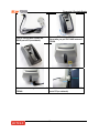
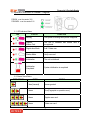
1
Fingerprint & Proximity Reader USER’S MANUAL Fingerprint & Proximity Reader Rev.4.2.0 Fingerprint & Proximity Reader Table of Contents 1. Important Safety Instructions............................................................................3 2. General ................................................................................................................3 3. Features...............................................................................................................4 4. Identifying Supplied Parts .................................................................................4 5. Specification .......................................................................................................4 6. Product Overview ...............................................................................................5 6.1. Functions .....................................................................................................5 6.2 PRODUCT EXPLANATION ...........................................................................6 6.2.1 PANEL DESCRIPTION.........................................................................6 6.2.2. Color Coded & Wiring Table..............................................................6 7. Installation Tips & Check Point .........................................................................7 7.1. Recommended cable type and permissible length of cable....................7 7.2. Reader connection ......................................................................................7 8. Installation of the Product .................................................................................8 8.1. Mullion and Wall Mount...............................................................................8 8.2. System Initialization ....................................................................................9 8.3. Wire Connection of FGR006 .......................................................................9 8.4. Wire Connection of FGR006EX ..................................................................9 8.5. Network Connection of FGR006...............................................................10 8.6. Wiring Example..........................................................................................10 9. Communication.................................................................................................11 9.1. Address Setting for RS485 / RS422 Communication .............................11 9.2. Address Setting for RS232 Communication Port Connection ..............12 9.3. Address Setting for RS485 Communication Port Connection ..............12 10. Operation.........................................................................................................13 11. Operation Indication of Reader / Register ....................................................17 12. FCC Registration Information........................................................................18 13. Warranty and Service .....................................................................................19 14. RMA Request Form.........................................................................................20 2 Fingerprint & Proximity Reader 1. Important Safety Instructions When using your Single Door Controller, basic safety precautions should always be followed to reduce the risk of fire, electrical shock, and injury to persons. In addition, the following should also be followed: 1. Read and understand all instructions. 2. Follow all warnings and instructions marked on the product. 3. Do not use liquid cleaners or aerosol cleaners. Use a damp cloth for cleaning. If necessary, use mild soap. 4. Do not use this product near water, such as bath-tub, wash bowl, kitchen sink, laundry tub, in a wet basement, or swimming pool. 5. This product should be operated only from the type of power source indicated on the marking label. If you are not sure of the type of power supplied to your installation site, consult your dealer or local power company. 6. Never push objects of any kind into this product or through the cabinet slots as they may touch voltage points or short out parts that could result in fire or electric shock. Never spill liquid of any kind on the product. 7. To reduce the risk of electric shock, do not disassemble this product by yourself, but take it to qualified service whenever service or repair is required. Opening or removing the covers may expose you to dangerous voltages or other risks. Also, incorrect reassembly can cause electric shock when the unit is subsequently used. 8. Unplug this product from the Direct Current (DC) power source and refer to qualified service personnel under these conditions: a. When the power supply cord or plug is damaged or frayed. b. If liquid has been spilled on the product. c. If the product does not operate normally after following the operating instructions in this manual. Adjust only those controls that are covered by the operating instructions in this manual. Improper adjustment of other controls that are not covered by this manual may damage the unit and will often require extensive work by a qualified technician to restore normal operation. d. If the product exhibits a distinct change in performance. 2. General The STAR FGR006 is a Biometrics and Proximity Reader which is compatible to existing proximity readers. The STAR FGR006 can be connected to any existing access control panel and you will have personal authorization by one’s fingerprint to avoid any access from un-authorized person. The STAR FGR006 has built-in proximity reader (The STAR FGR006EX has external reader port) and fingerprint module so that the access is only allowed when the personal ID and fingerprint are authorized. Its modern design gives you an easy installation (just replace existing reader) to metal door frame (mullion) or to any flat wall surface. The STAR FGR006 ensures you a successful operation where you want biometrics access control. The STAR FGR006 has three LED of red, green and lens(upper right), inside beeper sound to guarantee you an accurate and reliable access control. 3 Fingerprint & Proximity Reader 3. Features - Proximity/PIN and Fingerprint Verification - Dual fingerprints registration - Stores up to 1,000/2,000/4.000 Fingerprints - 1:1Verification and 1: N Identification - RS232 communication port for upload/download Fingerprints using PDA or Notebook (Optional) - Registration / Verification mode using Master Card - Off-line Add/Delete function using Master Card - External Reader Port to work with existing Proximity Reader - (26bit Wiegand) or Keypad / Magnetic stripe Reader(FGR006EX) - 26bit Wiegand, ABA TrackⅡ - High Protection from Scratch and ESD (Electro Static Discharge) - Tamper switch - High Quality Optical Sensor 4. Identifying Supplied Parts Please unpack and check the contents of the box. Main Unit Bezel User’s Manual RS232 Serial Port (Optional) 5. Specification CPU Memory Power / Current User Reader Port (FGR006EX only) Data Format Output Format Communication LED Control Input 32bit Microprocessor and Dual 8bit Microprocessor Program Memory : 64KB EEPROM DC 12V / Max. 350mA 1,000 / 2,000 / 4,5000 available 1ea of external reader port 26bit Wiegand, 8bit burst Format for keypad reader 26bit Wiegand, ABA Track II Magstripe format (Caution : Card Present signal is Open Collector) RS232, RS485, RS422(default, up to 255ch) selectable 4800bps and 9600bps (Default) 19200bps, 38400bps, 57600bps and 115200bps (Optional) Low active, maximum 20mA current drain (RS485) 4 Buzzer Control Input Tamper Switch LED Indicator / Beeper Color Operating Temperature Operating Humidity Dimension (W x H x D) Weight Fingerprint & Proximity Reader Low active, maximum 20mA current drain (RS485) Low active 3 LED Indicators / Piezo Buzzer Light and Dark Gray -15℃ to 40℃ (-5℉ to 104℉) 10% to 90% relative humidity non-condensing 2.6"x5.1"x2.0" (66x129x51mm) 230g (0.5 lbs) 6. Product Overview 6.1. Functions The FGR006 is finger reader with integrated proximity reader and registration terminal. Registration Mode The registration mode registers or eliminates user cards. Reader Mode This function uses as reader. RF Only Mode : If card data is authorized, card ID will be transmitted to controller. RF + FINGER Mode : If fingerprint data is authorized, card ID will be transmitted to controller. Master Card A master card is used when it changes mode each other. Card Number Output Form If your fingerprint is authorized then output becomes the card number to 26bit Wiegand or ABA Track II according to an output type. Error Signal Output If your fingerprint is not authorized then FGR006(FGR006EX) will generate finger error signal for 500ms of low active pulse.(Only available when your FG006(FGR006EX) is set to 26bit Wiegand output) This signal is open collector. Card Number Input Form This function is only available when you use FGR006EX. 5 Fingerprint & Proximity Reader FGR006EX is input the card number in the outside but FGR006 is contained internally. It takes a card input in a 8bit Burst or 26bit Wiegand or ABA Track II form. 6.2 PRODUCT EXPLANATION 6.2.1 PANEL DESCRIPTION 6.2.2. Color Coded & Wiring Table IO PORT NAME SIGNAL NAME POWER Main Power(+12V) +12V Power Ground GND INPUT (Only available with RS232/RS485 Communication) LED Control Input LED Buzzer Control Input BEEP WIEGAND OUTPUT Wiegand Data-0 DATA0 Wiegand Data-1 DATA1 COLOR CODED RED BLACK BROWN BLUE GREEN WHITE * Finger Error ERROR ORANGE * Note that the Finger Error output is only available with Wiegand output. ABA TRACK II OUTPUT Card Present CLS Orange Clock CLK White Data DATA Green RS485 COMMUNICATION PORT RS485-A 485A Gray RS485-B 485B Yellow 6 Fingerprint & Proximity Reader RS422 COMMUNICATION PORT Î DEFAULT RS422 TX+ RS422 TX+ RS422 TXRS422 TXRS422 RX+ RS422 RX+ RS422 RXRS422 RXTAMPER SWITCH Tamper Switch Tamper Switch EXTERNAL READER PORT (FGR006EX Only) Wiegand Data-0 Wiegand Data-0 Wiegand Data-1 Wiegand Data-1 RS422 TX+ RS422 TXRS422 RX+ RS422 RXTamper Switch Wiegand Data-0 Wiegand Data-1 7. Installation Tips & Check Point 7.1. Recommended cable type and permissible length of cable Description Cable Specification Maximum Distance Belden #9512, 22 AWG Reader (Power and Data) 4 conductor, shielded 150m Reader -> ACU Belden #9514, 22 AWG 8 conductor, shielded * Need thicker wire if you connect the reader with high current consumption. 7.2. Reader connection If you install the reader in a long distance between the ACU and the reader, you have to remind that there will be a voltage drop between both ends of GND wire. For example, if you connect a reader with 100mA current consumption at 100m distance (assume to using DC resistance of cable of 100Ω/100m) and the reader power is supplied from the ACU, the voltage drop of the GND wire will be 1V. In this case, the Wiegand data signal can not be measured lower than 1V. The most of ACU is capturing the signal by the voltage level of data input and 1V is the critical point whether the ACU read the data logic “1” or logic “0” therefore the reader output can not be read correctly from the ACU. You have to think about how you reduce the voltage drop between both ends of GND wire. There will be two methods to reduce the voltage drop and ACU can read data correctly. Reduce the DC resistance of GND wire; Using thick cable or add more wires to GND wire in parallel. If you connect 4 wires in parallel for GND, the DC resistance of GND wire will be reduced to 1/4 of single wire. Use separate power for the reader; Disconnect +12V wire from the ACU and connect external power supply to the reader nearby then there will be no current flow through the GND wire and no voltage drop between both ends of GND wire. 7 Fingerprint & Proximity Reader Shield EARTH GND < Reader connection using additional wires > EARTH GND Shield < Reader connection using external power supply > 8. Installation of the Product 8.1. Mullion and Wall Mount 8.1.1 Drill two Ø1/8"(3mm) holes, 4.4"(113mm) apart in vertical and drill one Ø1/2" hole for the reader cable 2.2"(56mm) apart from the top hole. 8.1.2 Connect wires between the control panel and FGR006 reader then put reader cable into the center hole and install the main unit by using two 3-16 screws. 8.1.3 Put bezel into the main unit then push bezel until you hear the locking sound. 8 Fingerprint & Proximity Reader 8.2. System Initialization You can H/W initialize using DIP switches. First, turn on the system power and turn off all DIP switches. Set DIP switches after an initialization completion. * DIP Switch as used as address of RS422/RS485 communication. An Initialization situation refers to the "11.Operation Indication of Reader / Register" of manual. 8.3. Wire Connection of FGR006 8.4. Wire Connection of FGR006EX 9 Fingerprint & Proximity Reader 8.5. Network Connection of FGR006 8.6. Wiring Example 8.6.1 Power - Connect (+) wire of DC 12V power to Red wire - Connect Power GND(-) wire of DC 12V to Black wire 8.6.2 Input Connection (Only available with RS232/RS485 communication) - A green LED turns on if the short does LED CONTROL INPUT wire with the GND. - The beep sound appears if the short does BEEPER CONTROLER INPUT wire with the GND. 10 Fingerprint & Proximity Reader 8.6.3 Output Connections [ 26bit Wiegand Output] [ABA Track II Output] 8.6.4 External Reader Connection (FGR006EX Only) 9. Communication A communication setting up is basically RS422. If you need the change of the communication mode separate FGR006(FGR006EX) and must set the jumper of MAIN PCB part. A jumper setting up uses a soldering iron. 9.1. Address Setting for RS485 / RS422 Communication There is 8bit DIP SW for address setting and it turns to 8bit binary code as below and each bit has fixed address value, the address is calculated the sum value of each bit set to “1” position. 11 Fingerprint & Proximity Reader 9.2. Address Setting for RS232 Communication Port Connection You should use external RS232 serial cable. - Connect connector for serial communication finished wiring on COM1 or COM2 port of PC. - Install application software and then execute it. ※ Please refer to 10.5 External RS232 Serial Jack (OPTION 2) 9.3. Address Setting for RS485 Communication Port Connection FGR006(FGR006EX) Wire GRAY YELLOW RS485-A RS485-B CNP-200A Converter Wire RED GRAY RS485-A RS485-B Set the jumper as shown in the figure above. RS-485/RS-232 converter is required to connect serial communication RS485 between Main Unit and PC(Personal Computer). The converter is CNP200A. - Connect RS485 A, Gray wire of Main Unit to Red wire of CNP200A converter. - Connect RS485 B, Yellow wire of Main Unit to Gray wire of CNP200A converter. - Plug the RS232 9-pin connector of CNP200A converter into COM1 or COM2 Port of PC. - Install and run the application software. 12 Fingerprint & Proximity Reader 9.4. RS422 Communication Port Connection FGR006(FGR006EX) Wire YELLOW GRAY BLUE RS422-Tx[-] RS422-Tx[+] RS422-Rx[-] BROWN RS422-Rx[+] CNP-200A Converter Wire WHITE RxRED Rx+ BLACK TxBLUE Tx+ Set the jumper as shown in the figure above. RS422/RS232 converter is require to connect serial communication RS422 between Main Unit and PC(Personal Computer). The converter is CNP200A. - Connect RS422 Tx[-],Yellow wire of Main Unit to White wire(Rx[-] port) of CNP200A converter. - Connect RS422 Tx[+], Gray wire of Main Unit to Red wire(Rx[+] port) of CNP200A converter. - Connect RS422 Rx[-], Blue wire of Main Unit to Black wire(Tx[-] port) of CNP200A converter. - Connect RS422 Rx[+], Brown wire of Main Unit to Blue wire(Tx[+] port) of CNP200A converter. - Plug the RS232 9-pin connector of CNP200A converter into COM1 or COM2 Port of PC. - Install and run the application software 10. Operation 10.1. Master Card Registration Mode 10.1.1 Master Card Registration The card presented to the FGR006 for the first time after initialization becomes the master card. A master card registration mode situation refers to the "11.Operation Indication of Reader / Register" of manual. ※ Note: Master card is not using the master fingerprint 10.1.2 Master Card Change You can register Master Card again after initialization of hardware. ※ CAUTION : If you initialize hardware, all user data are deleted. You can change master card by using the application software. Using the application software keeps the user data unchanged. Please refer the FGR006 software manual for download master card. 10.1.3 Master Card Function. It is used as the key to change reader and registration mode mutually ※ For example In the Reader mode if you access master card, it is changed to registration mode. In the Registration mode if you access master card again, it is changed to reader mode. 13 Fingerprint & Proximity Reader 10.2. Reader Mode 10.2.1 Reader Mode Function. A reader mode authorize user card. If your fingerprint is authorized then the output is your card ID. If your fingerprint is not authorized then output is error signal. A reader mode situation refers to the "11.Operation Indication of Reader / Register" of manual. 10.2.2 Authorization Method Present proximity card to the FGR006 Present proximity card to the external reader(FGR006EX only) If your card ID is registered, fingerprint scanner will light on. If your card ID is not registered, FGR006(FGR006EX) will make 2 beep sounds and return to the reader mode. 9 RF + FINGER MODE: Put your finger on the fingerprint scanner for authorization. If your fingerprint is authorized then FGR006(FGR006EX) will turn on the lens. LED(upper light) indicator make a beep sound for a second and send your card ID to the access controller. 9 RF Only: If card is authorized only without using fingerprint, LED(upper light) indicator make a beep sound for a second and send your card ID to the access controller. If your fingerprint is not authorized then FGR006(FGR006EX) will make 2 beep sounds and generate finger error signal for 500ms of low active pulse.(Only available when your FGR006(FGR006EX) is set to 26bit Wiegand output) 10.3. Registration Mode 10.3.1 Registration Mode Function The mode is the register an user card or to delete. It deletes the card when an user card is registered. (4 beeps sounds) It registers the card when an user card is not registered. (3 beep sounds) 10.3.1 User Card Registration. 9 RF + FINGERPRINT MODE: After reading user’s card, you should register fingerprint two times. Present the proximity card to the FGR006 Present the proximity card to the external reader (FGR006EX only) Put the fingerprint when red light is illuminated on the fingerprint scanner. Put the fingerprint again on the fingerprint scanner when the red light is illuminated again after the red light turns off. It beeps 3 times when the registration is completed. 14 Fingerprint & Proximity Reader 9 RF Only: Don’t place your finger on fingerprint scanner after reading user’s card. It beeps 3 times when the registration is completed. Register by method such as above, if there are cards to register additionally. After registration present proximity master card again, and it is changed to the reader mode. It beeps 2 times when the registration is not correct. 10.3.2 User Card Deletion Present the proximity card to the FGR006 Present the proximity card to the external reader(FGR006EX only) It beeps 4 times when the deletion is completed. After deletion present proximity master card again, and it is changed to the reader mode. It beeps 2 times when the deletion is not. 10.4. Identification Function (OPTION 1) This function operates in the Reader mode. User can be verified with Fingerprint template only. (No card necessary) Sensor will be activated automatically when user place the fingerprint on the fingerprint scanner. ※ CAUTION : This function must be applied when the number of user is less than 100. If your fingerprint is authorized then FGR006(FGR006EX) will turn on the lens led(upper light) and make a beep sound for a second and will send your card ID to the access controller. If your fingerprint is not authorized then FGR006(FGR006EX) will make 2 beep sounds and generate finger error signal for 500ms of low active pulse.(Only available when your FGR006 (FGR006EX) is set to 26bit Wiegand output) 10.5. External RS232 Serial Jack (OPTION 2) This function use in FGR006 to PC(or Notebook) when it connect directly. This function is possible the software though FGR006 are established to a stand alone type. 15 Fingerprint & Proximity Reader It use to connect with FGR006 and RS232 port of PC(or notebook). It uncover TOP CASE in FGR006. Extract after you pull TOP CASE bottom of FGR006. It insert RS232 serial jack at bottom of It connect a d-sub connector with RS232 FGR006 port of PC (or notebook). 16 Fingerprint & Proximity Reader 11. Operation Indication of Reader / Register FGR006 : over the version 3.00 FGR006EX : over the version 3.00 11.1. LED Indicators Status LED STATUS FUNCTION Booting The system is booting when power is supplied Register Master Card The unit is initialized and master card is unregistered Registration Mode Add / Delete user Reader Mode Verify user card Initialization The unit is initialized Initialization Completed System initialization is completed 11.2. Buzzer Sound Status BEEP SOUND TIMES STATUS 1 time(1second) Access granted. 2 times Error(Fingerprint or operation error) 3 times Register user card. 4 times Delete user card. 17 Fingerprint & Proximity Reader 12. FCC Registration Information FCC REQUIREMENTS PART 15 Caution: Any changes or modifications in construction of this device which are not expressly approved by the responsible for compliance could void the user's authority to operate the equipment. NOTE: This device complies with Part 15 of the FCC Rules. Operation is subject to the following two conditions; 1. This device may not cause harmful interface, and 2. This device must accept any interference received, including interference that may cause undesired operation. This equipment has been tested and found to comply with the limits for a Class A Digital Device, pursuant to Part 15 of the FCC Rules. These limits are designed to this equipment generates, uses, and can radiate radio frequency energy and, if not installed and used in accordance with the instructions, may cause harmful interference to radio communications. However, there is no guarantee that interference will not occur in a particular installation. If this equipment does cause harmful interference to radio or television reception, which can be determined by turning the radio or television off and on, the user is encouraged to try to correct interference by one or more of the following measures. 1. Reorient or relocate the receiving antenna. 2. Increase the separation between the equipment and receiver. 3. Connect the equipment into an outlet on another circuit. 4. Consult the dealer or an experienced radio/TV technician for help. 18 Fingerprint & Proximity Reader 13. Warranty and Service The following warranty and service information applies only to the United States of America and the Republic of Korea. For information in other countries, please contact your local distributor. To obtain in or out of warranty service, please prepay shipment and return the unit to the appropriate facility listed below. UNITED STATES OF AMERICA RF LOGICS Inc. Service Center 370 Amapola Ave. #106, Torrance, CA 90501 Tel.: 310-782-8383 Fax: 310-782-8292 E-mail: [email protected] Web-site: www.rflogics.com OUTSIDE OF THE UNITED STATES IDTECK CO., LTD. Service Center 5F Ace Techno Tower B/D. 684-1 Deungchon-dong, Gangseo-gu, SEOUL 157-030, KOREA Tel.: +82 - (2) - 2659-0055 Fax: +82 - (2) - 2659-0086 E-mail: [email protected] Web-site: www.idteck.com Technical Support (in Korea) E-mail: [email protected] Hotline: +82-16-604-8965 (Customer support) +82-17-340-4170 (R&D) Please use the original container, or pack the unit(s) in a sturdy carton with sufficient packing to prevent damage and include the following information: 1. A proof-of-purchase indicating model number and date of purchase. 2. Bill-to Address. 3. Ship-to Address. 4. Number and description of units shipped. 5. Name and telephone number of person to be contacted. 6. Reason for return and description of the problem (Should be as detailed as possible!) NOTE: Damage occurring during shipment is deemed the responsibility of the carrier, and claims should be made directly to the carrier. 19 Fingerprint & Proximity Reader 14. RMA Request Form • RMA REQUEST FORM : ORIGINAL IDTECK Co., Ltd. 5F, Ace Techno Tower B/D, 684-1, Deungchon-Dong, Gangseo-Gu, Seoul, 157-030, Korea TEL : +82-2-2659-0055, FAX ; +82-2-2659-0086, www.idteck.com RMA REQUEST FORM Send to: RMA Customer Service 5F, Ace Techno Tower B/D 684-1, Deungchon-Dong, Gangseo-Gu Seoul, 157-030, Korea Sales Person In Charge Shipping Port : Air / Vessel : NO Model Serial Number 1 2 3 4 5 Engineer Comment Engineer Comment Engineer Comment RMA No. & Date : Original Invoice No. & Date : Requested from : Departure Date : Error Check Box by shipper RS 232 Com. □ Power □ Card Reading □ Input/Output □ Keypad □ RS 422 Com □ Others □ : RS 232 Com. □ Input/Output □ Card Reading □ RS 422 Com □ Power □ Keypad □ Card Reading □ RS 422 Com □ Power □ Keypad □ Card Reading □ RS 422 Com □ Power □ Keypad □ Card Reading □ RS 422 Com □ Others □ : RS 232 Com. □ Input/Output □ Others □ : RS 232 Com. □ Input/Output □ Engineer Comment Others □ : Engineer Comment RS 232 Com. □ Input/Output □ Others □ : Manufacture’s Verification Product Defective : User’s Misuse : Communication Error : Packing Details Dimension(L:W:H) : Net & Gross Weight : Power □ Keypad □ Installation Error : Connection Error : Others : No. of Units: No. of Boxes: Requested by: Received by: Signature of Buyer Signature of IDTECK 20 Fingerprint & Proximity Reader • RMA REQUEST FORM : SAMPLE IDTECK Co., Ltd. 5F, Ace Techno Tower B/D, 684-1, Deungchon-Dong, Gangseo-Gu, Seoul, 157-030, Korea TEL : +82-2-2659-0055, FAX ; +82-2-2659-0086, www.idteck.com RMA REQUEST FORM Send to: RMA Customer Service 5F, Ace Techno Tower B/D 684-1, Deungchon-Dong, Gangseo-Gu Seoul, 157-030, Korea Sales Person in Charge: Karina Kwak Shipping Port : Narita Air / Vessel : Air NO Model Serial Number SR 10 XXXXXXXXXXXXX 1 Engineer Write problem (must be Comment detailed). others 2 3 4 5 Engineer Comment Engineer Comment Engineer Comment Engineer Comment Manufacturer’s Verification Product Defective : User’s Misuse : Communication Error : Packing Details Dimension(L:W:H) : 30 * 25 * 80 Net & Gross Weight : 150g Requested by: XXXX YYYY Signature of Buyer RMA No. & Date :. We will send this No. , if needed. Original Invoice No. & Date : 00-00-0-000 / 2005.10.01 Requested from : Mr. XXXX YYYY ABC Company Address: Country: Departure Date : 2005, 10. 15 Error Check Box by Shipper RS 232 Com. □ Power ▣ Card Reading ▣ Input/Output □ Keypad □ RS 422 Com □ Others □ : RS 232 Com. □ Input/Output □ Power □ Keypad □ Card Reading □ RS 422 Com □ RS 232 Com. □ Input/Output □ Power □ Keypad □ Card Reading □ RS 422 Com □ Others □ : RS 232 Com. □ Input/Output □ Power □ Keypad □ Card Reading □ RS 422 Com □ Others □ : RS 232 Com. □ Input/Output □ Power □ Keypad □ Card Reading □ RS 422 Com □ Others □ : Others □ : Installation Error : Connection Error : Others : No. of Units: No. of Boxes: 20 2 Received by: Signature of IDTECK 21 Fingerprint & Proximity Reader MEMO 22 Fingerprint & Proximity Reader MEMO 23 Fingerprint & Proximity Reader The specification contained in this manual are subject to change without notice at any time. 5F, Ace Techno Tower B/D, 684-1, Deungchon-Dong, Gangseo-Gu, Seoul, 157-030, Korea Tel : (82) 2 2659-0055 Fax : (82) 2 2659-0086 E-mail : [email protected] NOV. 2005 Copyright ©2005 IDTECK Co., Ltd.