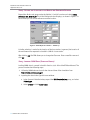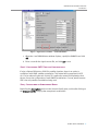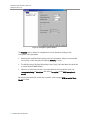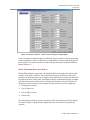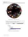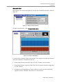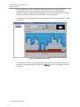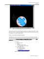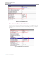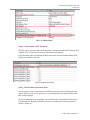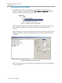
1
Application Note 121 Testing Real-World A-GNSS Performance in the Lab using ULTS September 2009 Real-World Lab Simulation with ULTS Application Note 121 SPIRENT 541 Industrial Way West Eatontown, NJ 07724 USA Email: Web: [email protected] http://www.spirent.com Page Part Number: 71-006072, Version A0 AMERICAS 1-800-SPIRENT • +1-818-676-2683 • [email protected] EUROPE AND THE MIDDLE EAST +44 (0) 1293 767979 • [email protected] ASIA AND THE PACIFIC +86-10-8518-2539 • [email protected] © 2009 Spirent. All Rights Reserved. All of the company names and/or brand names and/or product names referred to in this document, in particular, the name “Spirent” and its logo device, are either registered trademarks or trademarks of Spirent plc and its subsidiaries, pending registration in accordance with relevant national laws. All other registered trademarks or trademarks are the property of their respective owners. The information contained in this document is subject to change without notice and does not represent a commitment on the part of Spirent. The information in this document is believed to be accurate and reliable; however, Spirent assumes no responsibility or liability for any errors or inaccuracies that may appear in the document. 2 Spirent Application Note Real-World Lab Simulation with ULTS Table of Contents Table of Contents Introduction............................................................................................... 1 Why Test Beyond Conformance? ................................................................ 2 Lab Simulation of Real-World Scenarios .................................................... 3 Satellite Simulation ............................................................................................ 3 Environmental and Device Antenna Characteristics ............................................. 4 Network Simulation ............................................................................................ 4 Automation Software .......................................................................................... 5 Creating a Real-World Scenario with ULTS ................................................. 6 Real-World Scenario Survey................................................................................ 6 Device-Specific A-GNSS Antenna Pattern............................................................. 8 Scenario File Creation (SimGEN) ......................................................................... 8 Step 1: Using an existing scenario ...........................................................................9 Step 2: Basic elements of scenario configuration .....................................................9 Step 3: Setting the Date, Time, and Duration of the Simulation ................................11 Step 4: Setting the Location of the Mobile and Reference Receiver .......................... 12 Step 5: Loading YUMA Data (Satellite Orbits) ......................................................... 12 Step 6: Configuring GNSS Satellite Constellations.................................................. 13 Step 7: Configuring an Atmospheric Model ............................................................ 13 Step 8: Modeling Multi-path Effects........................................................................15 Step 9: Configuring an antenna pattern ................................................................. 19 Test Configuration (TestDrive ULTS) .................................................................. 22 Step 1: Loading a Spirent GPS Performance Test .................................................... 23 Step 2: Configuring the Number of Measurements and UE Location ........................ 23 Step 3: Configuring Protocol-Related Parameters................................................... 24 Step 4: Configuring a GPS Scenario ....................................................................... 25 Step 5: Configuring Assistance Data ...................................................................... 25 Step 6: Pass/Fail Criteria .......................................................................................26 Step 7: Test Execution............................................................................................26 Conclusion............................................................................................... 28 Appendix A – Moving Scenarios............................................................... 29 Time-Ordered Motion Commands ............................................................... 30 Motion Data Imported from NMEA............................................................... 31 Accuracy........................................................................................................... 32 Spirent Application Note 3 Real-World Lab Simulation with ULTS Application Note 121 Replication of real-life situations....................................................................... 32 Map-Matched routes ........................................................................................ 32 Real-time motion commands from an external system....................................... 32 Appendix B – Signal Obscuration............................................................. 33 Simulating Physical Obstructions ............................................................... 34 Roadside Buildings and Cuttings................................................................ 34 Bridges ..................................................................................................... 35 Tunnels and Covered Car Parks .................................................................. 35 Natural Surrounding Terrain ....................................................................... 36 Adjacent and Passing vehicles, Highway Equipment.................................... 37 On-Vehicle Obscuration ............................................................................. 37 4 Spirent Application Note Real-World Lab Simulation with ULTS Introduction INTRODUCTION The rapidly-growing location based services (LBS) application market, as well as emergency location mandates (such as E911 in the US), have resulted in tremendous growth in the number of mobile devices that support A-GPS. This application note discusses a lab-based methodology that helps to ensure end-user satisfaction with LBS by thoroughly testing the performance of the enabling location technology under representative real-world conditions. It describes in detail the elements of this methodology and their implementation in Spirent’s UMTS Location Technology solution (ULTS). Spirent Application Note 1 Real-World Lab Simulation with ULTS Application Note 121 WHY TEST BEYOND CONFORMANCE? End-user satisfaction with LBS is highly dependent on the real-world performance of the technologies that enable them. It is therefore very important for device manufacturers and mobile operators to thoroughly test the performance of A-GPS (hereafter referred to as A-GNSS, to take into account GLONASS and other constellations) in a real-world setting. Because current industry-defined Conformance testing methodologies assume conducted (directly connected) transmission of RF signals under ideal GNSS conditions, they do not provide all the data necessary to ensure good real-world performance of mobile devices. An alternative is field testing, which can provide valuable system performance data. However, the constantly-changing environmental conditions in the field, and the lack of control over them, can get in the way of understanding how the various components affect the performance of a location system. There is a clear industry need for a middle ground that combines the advantages of these testing methods while mitigating their disadvantages, for instance, a test methodology that offers all of the advantages and convenience of lab-based testing, while effectively taking into account the vagaries of the real world. It is impossible to completely replicate in the lab all the conditions found in the real world, but it is possible to identify and simulate the key characteristics that influence device performance. 2 Spirent Application Note Real-World Lab Simulation with ULTS Introduction LAB SIMULATION OF REAL-WORLD SCENARIOS A lab-based simulation approach involves piecing together several distinct elements of the environment that affect GNSS performance. These elements, when defined and integrated properly, provide a representation of the real world. While simulation may not be able to reproduce the full richness of real world conditions, it is ideal for repeatable characterization and optimization of receiver performance, especially when combined with other methods of testing. Effective simulation requires an understanding of the particular elements of the environment that affect device performance, which are then separately modeled by appropriate hardware and software. These elements are then combined into a final system, which represents a synthesis of their separate effects. At a high level, the two core components of any simulation are GNSS (GPS, GLONASS, etc.) simulation and cellular network (GSM, UMTS, CDMA) emulation. Lab Simulation can be broken down into four element groupings discussed in the next sections: 1. Satellite Simulation 2. Environmental and Device Antenna Characteristics 3. Network Simulation 4. Automation Software Satellite Simulation Simulation of the GNSS constellation allows for the simulation of moving satellites and a moving receiver. The key elements are: Location – The physical location of the receiver, expressed in terms of latitude, longitude and altitude. If the receiver is in motion, a route needs to be specified. Device Motion – The path taken by a device. This is needed in order to simulate a device that is moving (as opposed to staying in one place). Date, Time, and Length of Simulation – Directly related to the visibility of satellites for a given location. The date and time can be specified to be any point in the past, present, or future. Satellite Orbits – The actual satellites available in the sky for a given date, time and location. They can be obtained from YUMA data, maintained by the US Navy. GNSS Satellite Constellations – The satellite constellations being simulated. Although GPS is still by far the most common, GLONASS is gaining momentum and others are coming, including Galileo and QZSS. Spirent Application Note 3 Real-World Lab Simulation with ULTS Application Note 121 Environmental and Device Antenna Characteristics GNSS signals are transmitted wirelessly and are therefore subject to many environmental and device antenna factors. These elements are responsible for the majority of performance variations from device to device. Since they are also the most difficult to simulate correctly, they need special attention: Multi-path/Fading Emulation – A suitable multi-path model must be created, based on the geographic elements of the given location, such as buildings, trees, rocks, etc. Atmospheric Modeling – Simulation of atmospheric conditions is required to test the ability of the GNSS system to compensate for resultant navigation error. Signal Obscuration – The attenuating effect of physical elements, such as buildings and trees, on incoming GNSS signals from the sky must be accounted for. Device Antenna Pattern – As more capability gets crammed into shrinking mobile devices, the GNSS antenna performance becomes a critical factor. To simulate realworld performance in the lab, the antenna pattern must be characterized and simulated. Network Simulation For A-GNSS, it is also necessary to simulate the cellular network and the assistance data that it provides to the mobile device. The main elements are: Flexible Simulation – The network simulator must be capable of supporting all the cellular technologies required by the device under test, whether GSM/GPRS, UMTS and/or CDMA. The minimum requirements are typically: Support for 3G and 2G location protocols (such as RRC/RRLP). Ability to initiate common signaling procedures (such as voice calls and supplementary services). Flexibility to modify key protocol information elements (such as desired horizontal accuracy and desired response time). SMLC/PDE Simulation – Required for control of assistance data delivery and position calculation—both cornerstones of the A-GNSS system. It is important that this simulation be flexible so that the configuration can be aligned as closely as possible with the real network. 4 Spirent Application Note Real-World Lab Simulation with ULTS Introduction Automation Software This ties everything together and controls the test settings, procedure, collection and organization of data, and presentation of results. Simulation Parameters – Easy configuration of key parameters of the simulation components mentioned above. May include: Delivery of assistance data Specifying initial location Specifying the number of measurements Protocol and call flow selection. Test Scenario – Determines the timing and flow of test execution. A properlydesigned test scenario should be able to replicate real-world scenarios much faster than is possible with field test or record-and-playback approaches. Test Results – Includes analysis yielding common metrics and KPIs used to assess the A-GNSS device performance, as well as detailed protocol logs and positioning data: Sigma 1 and 2 calculations for horizontal error. Yield calculations. Time to first fix (TTFF). Graphical representation of data, including CDF and PDF. Spirent Application Note 5 Real-World Lab Simulation with ULTS Application Note 121 CREATING A REAL-WORLD SCENARIO WITH ULTS To illustrate the process, we start with the widely familiar example of Times Square in New York City; a very challenging scenario for GNSS devices. Tall buildings obscure most of the view of the sky and create a very complex multi-path environment, so almost all devices have difficulty getting consistent and accurate position fixes from available GNSS signals in this location. It is therefore a very useful scenario for benchmarking device performance and optimizing a design to perform well in urban environments. The approach to replicating this scenario in the lab can be broken down into four groups, which form a recommended sequence that can be applied in all cases: 1. Real-World Scenario Survey 2. Device-Specific A-GNSS Antenna Pattern (Optional) 3. Scenario File Creation (SimGEN) 4. Test Configuration (TestDrive ULTS) Real-World Scenario Survey The following aspects need to be captured to understand the simulated real-world scenario: Latitude and Longitude. A picture of the surroundings, including all buildings and other obstructions. For a moving device, the exact path should be captured on a map. For the Times Square example, a location in the middle of Broadway by the Marriot Marquis Hotel has been chosen. The exact location is: 40.758623 N, 73.985404 W. To simulate the signal obscuration and multi-path characteristics of this location, a fish-eye picture was taken at the exact location. Figure 1 provides a good understanding of the physical environment around the device. 6 Spirent Application Note Real-World Lab Simulation with ULTS Introduction Figure 1: Fish-eye Capture of the Times Square Location To simplify this example, a non-moving scenario (the device remains stationary) is used. Refer to Appendix A for an explanation of how moving scenarios can be simulated with ULTS. Spirent Application Note 7 Real-World Lab Simulation with ULTS Application Note 121 Device-Specific A-GNSS Antenna Pattern This is an optional step in the simulation process. If the goal is to test only the performance of the GNSS chipset used by a device, this step is unnecessary. However, if the goal is to determine the complete end-user experience, accounting for all A-GNSS characteristics of the mobile device, then the antenna pattern is critical. For more information, refer to Spirent’s A-GPS Over the Air Test Method white paper. The A-GNSS antenna pattern describes the attenuation of GPS signals due to physical antenna characteristics. Typically, the antenna pattern contains loss values for a given azimuth and elevation pair; typical resolutions for azimuth and elevation range from 1- 5 degrees. The antenna pattern is obtained by making C/No measurements of the GNSS receiver placed in an anechoic chamber and rotated over different angular positions. To simulate the device’s GNSS antenna pattern in the lab, an OTA Antenna Pattern must be obtained for the device under test. Scenario File Creation (SimGEN) The scenario file in SimGEN contains all satellite, environmental, and antenna characteristic simulation information, including the following GNSS simulation elements: Device Location Device Motion (discussed in Appendix A) Date, Time and Length of Simulation Satellite Orbits GNSS Satellite Constellations Atmospheric Modeling Multi-path/Fading Simulation Signal Obscuration (discussed in Appendix B) Device Antenna Pattern To simulate the GNSS environment for a particular location, a “GPS Scenario” must first be configured using SimGEN. The scenario contains information necessary for the Satellite Simulator to accurately calculate the incident GPS signals for a receiver in that particular location, at a given date and time. 8 Spirent Application Note Real-World Lab Simulation with ULTS Introduction For this example; the front of the Marriott Marquis Hotel at Times Square, NY; the position attributes are: Latitude: 40.758623 N Longitude: 73.985404 W Altitude: 14 m Date of Simulation: 8/28/2009 Time of Simulation:00:00:00 (midnight) Duration of Simulation: 1 day Step 1: Using an existing scenario Because creating a GPS scenario from scratch is time-consuming; we recommend modifying an existing scenario by reconfiguring certain elements to conform to the selected location. The scenario file used in this example is GPS Scenario 1.scn. This scenario file contains the settings used for 3GPP 34.171 conformance test cases, but will be significantly modified to accommodate real-world effects. An advantage of this approach is that mobile device performance with the modified version can be compared to performance with the raw, unmodified original. Step 2: Basic elements of scenario configuration For those who are not familiar with the working of SimGEN, we recommend you first refer to Chapter 5 of the SimGEN User Manual. To access the manual from the SimGEN program, select Help>User Manual. Copy the GPS Scenario 1 scenario into a new directory and make all edits to the copy only. 1. Open the SimGEN software by selecting Start>Programs>SimGEN>SimGEN Application. The Open window displays. 2. Open the GPS Scenario 1.scn file on the ULTS System Controller PC under: C:\Program Files\Spirent Communications\TestDrive ULTS\GPS Scenarios\Conformance\34.108 SECTION 10.1.2. 3. After the scenario loads, select Save As. Enter a new Scenario Name (such as TimesSquare) and Location (such as C:\Times Square Scenario). 4. Click OK. All Scenario files are saved in the Location directory. Spirent Application Note 9 Real-World Lab Simulation with ULTS Application Note 121 After saving, the TimesSquare.scn file opens. To view the scenario in Engineering Layout, shown in Figure 2, select Window>Engineering Layout. Figure 2: Scenario Window – TimesSquare.scn The column on the left side displays important scenario settings, as shown in Figure 3. Figure 3: Scenario Settings 10 Spirent Application Note Real-World Lab Simulation with ULTS Introduction The following list provides detailed information on the Scenario Settings: Atmosphere – This group contains settings relating to elements of the atmosphere, such as inclusion of tropospheric delay, etc, ionosphere model, etc. Configuration of this section will be described later. For purposes of this introduction, default settings are used. GPS Constellation – This contains important settings relating to satellite motion and signal control. The main use of this section is to import YUMA almanac data, as well as intentionally introduce orbital errors. Vehicle 1 “reference receiver” – This represents the base station in a cellular network, and contains settings such as location of the base station. Vehicle 2 “mobile” – This represents the mobile receiver. Apart from setting its location, an antenna pattern as well as a multi-path mask can be specified. Step 3: Setting the Date, Time, and Duration of the Simulation To set the date, time, and duration of the scenario, select Start time from the top left of the scenario layout toolbar, as shown in Figure 4. The Start Time and Duration window displays, as shown in Figure 5. Figure 4: Start Time Setting Figure 5: Start Time and Duration Window Spirent Application Note 11 Real-World Lab Simulation with ULTS Application Note 121 Step 4: Setting the Location of the Mobile and Reference Receiver Expand the Motion sub-group under the Vehicle 2 “mobile” receiver and select initial reference file: Mobile.ref. The Initial Settings window displays, as shown in Figure 6. In this window you can set the reference receiver location. Figure 6: Initial Reference Window – Mobile.ref A similar selection is made for the location of the base station. In general, the location of the mobile would be expected to be within 3 KM of a base station. After clicking OK, SimGEN allows you to change the file name. Enter a new file name and click OK. Step 5: Loading YUMA Data (Satellite Orbits) Loading YUMA data is covered in detail in Section 9.9.6 of the SimGEN User Manual. The process involves the following steps: 1. Collecting YUMA almanac data for the date and time of the simulation from http://www.navcen.uscg.gov. 2. Inputting the data in the Signal Sources window. a. In the Scenario Details window, expand the GPS Constellation group, and select Default.gps. b. Select Orbits and click Load Yuma. 12 Spirent Application Note Real-World Lab Simulation with ULTS Introduction Figure 7: Signal Sources Window – Load Yuma Button c. When the Load YUMA Almanac window displays, specify the YUMA file and click OK. d. Enter a name for the signal sources file, and click OK to save. Step 6: Configuring GNSS Satellite Constellations If using a Spirent GSS8000 or GSS6700 satellite simulator, there is an option to configure a multi-GNSS satellite constellation. This feature will be supported in ULTS v5.0—to be released by the end of 2009. This application note will be updated at that time to discuss the configuration of multi-GNSS constellations. For now, we will assume GPS is the only satellite constellation being used. Step 7: Configuring an Atmospheric Model Expanding the Atmosphere section in the Scenario Details pane, and double clicking on the Atmosphere File brings up the atmospheric model editor. Spirent Application Note 13 Real-World Lab Simulation with ULTS Application Note 121 Figure 8: Atmosphere Options Window The General section allows for configuration of basic elements relating to the ionosphere and troposphere. Selecting the model that the receiver uses for Tropospheric delay is recommended for accuracy. In this example, the default, STANAG, is used. The default value of Surface Refractivity Index (324.8) indicates Mean Sea level and is used with the STANAG Model. Selection of a terrestrial model is recommended for the ionospheric delay: set Ionospheric Delay to Modelled and select Terrestrial as the GPS ionospheric model. By selecting the terrestrial model, the constants in the category GPS terrestrial iono Model are used. 14 Spirent Application Note Real-World Lab Simulation with ULTS Introduction Figure 9: Atmosphere Window – GPS Terrestrial Ionospheric Model Options For this example, the default values are sufficient; they are used to calculate delays due to the ionosphere, as well as coefficients in the Navigation data message at the start of the simulation. For more information on these values, please refer to the SimGEN User Manual Section 11. Step 8: Modeling Multi-path Effects The SimGEN software incorporates a Land Mobile Multi-path model which allows more ‘realistic’ multi-path simulation. The model allows automatic definition of the signal conditions through selection from a database of pre-defined environments for each test. The relative numbers of the direct and reflected signals are determined using a satellite visibility category mask, which uses the azimuth and elevation of the LOS signal, and allows you to set the criteria for each segment of the mask to one of four categories: 1. Complete Obscuration 2. Line of Sight Only 3. Line of Sight + Echoes 4. Echoes Only First, Azimuth and elevation points are marked on the fish-eye picture of Times Square, as shown in Figure 10. Note that the angular divisions do not need to be extremely accurate. Spirent Application Note 15 Real-World Lab Simulation with ULTS Application Note 121 Figure 10: Times Square – Azimuth and Elevation Points The SimGEN category mask editor for specifying land-mobile multi-path is an easy-to-use tool that allows you to quickly specify the reflection categories. To open the tool, select the multi-path file by expanding the ‘Vehicle 2’ contents in the scenario details section, expand Options and select Land mobile multi-path file, as shown in Figure 11. Figure 11: Selecting the Land Mobile Multi-Path File 16 Spirent Application Note Real-World Lab Simulation with ULTS Introduction Multi-path Editor Selecting the ‘Land mobile multi-path file’ setting opens the Multi-path Editor, shown in Figure 12. Figure 12: Multi-path Editor Window To begin using the editor, select Category mask editor. Figure 13: Category Mask Editor To use the editor, identify a region on the picture, and categorize it under one of the four multi-path categories. Some general rules are: A clear view of the sky would fit under ‘LOS only’, as there is no obscuration. Boundaries between a segment of the sky and an obscuration would be categorized as ‘LOS + echoes’ A surface may be categorized as ‘Echoes’ if there is a section of clear sky directly opposite its plane. Otherwise, the surface is an ‘Obscuration’. Spirent Application Note 17 Real-World Lab Simulation with ULTS Application Note 121 These simple rules are used to categorize the various regions of the picture. The corresponding boundaries of the regions are identified in terms of Azimuth and elevation. Finally, the appropriate category type is transcribed into the editor, using the Azimuth and elevation values of the boundaries to guide placement. The category mask, applied based on the example picture and the rules above, is shown in Figure 14. Figure 14: Completed Category Mask To ensure that the mask is in overall agreement with the picture itself (note that region placements are approximate), clicking on the 3D View button can be helpful, as shown in Figure 15. 18 Spirent Application Note Real-World Lab Simulation with ULTS Introduction Figure 15: Land Mobile Multi-path Category Mask – 3D View At this point, the land mobile multi-path configuration is complete and the file is saved. When the scenario is executed, the effects of the multi-path criterion, mentioned above, are applied to the various satellite signals. Step 9: Configuring an antenna pattern SimGEN features an Antenna Pattern Editor that allows you to model gain and phase characteristics and obscuration due to the antenna’s immediate surroundings. Open the Editor by expanding Vehicle 2>Antenna 1>Antenna Pattern Control. Select the Level pattern file under the Scenario Details pane, as shown in Figure 16. Figure 16: Opening the Antenna Pattern Editor Spirent Application Note 19 Real-World Lab Simulation with ULTS Application Note 121 The editor follows similar rules to the multi-path category mask editor discussed in the previous section. Values of antenna gain for various regions are identified in terms of Azimuth and Elevation. These values are then transcribed into the editor for the region represented by the Azimuth and Elevation values. In contrast to the Multi-path Mask Editor, the Antenna Pattern encompasses the entire sphere, instead of the upper hemisphere alone, as shown in Figure 17. Figure 17: Antenna Pattern Editor To use the Antenna Pattern Editor, input a value into the Modify text box, and paint through the region for that value, as shown in Figure 18. Figure 18: Using the Antenna Pattern Editor 20 Spirent Application Note Real-World Lab Simulation with ULTS Introduction The Antenna Pattern Editor can be used to store data in a CSV file. Many antenna manufacturers publish gain and phase patterns in CSV file format. This helps to avoid manual entry of the data via the antenna pattern editor. It is also possible to convert antenna gain pattern data obtained using ULTS in an A-GPS OTA test setup and import it into SimGEN. Spirent Application Note 21 Real-World Lab Simulation with ULTS Application Note 121 To import a CSV File: 1. Determine the degree of resolution for azimuth and elevation in the pattern file. Input this information into the editor by selecting Options>Settings. 2. Import the file by selecting File>Open. In the Open window, select Comma Separated Variable Files (.CSV) from the Files of type menu. 3. Browse to the location of the CSV file, and click Open. 4. Confirm that the antenna pattern editor displays the correct values by comparing them to the values in the CSV file. Close the editor, and save the scenario. Test Configuration (TestDrive ULTS) To complete the simulation, the TestDrive ULTS software must be used to configure the network simulation and automation parameters. This includes the following GNSS simulation elements: Cellular network settings 3G and 2G location protocols (e.g. RRC/RRLP) Signaling procedures (such as voice calls, supplementary services, etc) Protocol information elements, such as desired horizontal accuracy, desired response time, etc. SMLC settings Test scenario (test case) settings The TestDrive software can run several types of test scenarios. Each test scenario is executed by using ‘suite’ files, which may contain one or more tests. For more information about organization and execution methodology, please refer to the ‘ULTS user manual’. Most tests in the TestDrive ULTS software use predefined GPS scenarios, as mandated by the test specification they are directed toward. In order to use the custom scenario designed above, it is necessary to use the Spirent GPS performance series of tests. The Spirent GPS performance tests assist in the characterization of the overall performance of an LBS system. The hallmark of these tests are flexibility in defining a custom GPS scenario, as well as complete control over choice of protocol, definition of protocol elements, and pass fail criteria. For additional information, refer to Section 4.3.1 of the ULTS User Manual. 22 Spirent Application Note Real-World Lab Simulation with ULTS Introduction Step 1: Loading a Spirent GPS Performance Test Open the Spirent GPS Performance Test by selecting Suites>Spirent>GPS Performance, as shown in Figure 19. Figure 19: Accessing the GPS Performance Test After loading the default test, you should save a separate copy and make edits only to this copy. The default template is read-only; changes made cannot be saved for use in future sessions. In this example, the following Network Parameters are used: Network Type: 3G (RRC Control Plane) Network Initiated Location Request MS Based Sending of RRC Cold Start message A single voice call, with a 100 measurements. All other parameters are set to default. An outline of the process to configure a Spirent GPS performance test with the settings mentioned above follows. Step 2: Configuring the Number of Measurements and UE Location Configure the number of measurements and the UE Location by using the parameters under the General Parameters group, as shown in Figure 20. Spirent Application Note 23 Real-World Lab Simulation with ULTS Application Note 121 Figure 20: General Parameters Group Step 3: Configuring Protocol-Related Parameters You must configure parameters relating to the base station, including BTS location, Air Interface type, and downlink levels; as well as additional LBS parameters, as shown in Figure 21. Figure 21: GSM/WCDMA Network Parameters 24 Spirent Application Note Real-World Lab Simulation with ULTS Introduction Figure 22: LBS Parameters Step 4: Configuring a GPS Scenario The GPS scenario set-up in the last section must be integrated within the TestDrive ULTS software. This is done from the section ‘GPS Scenario parameters’. In this example, edits to the Default.SCN file have been saved under New Default.SCN. TestDrive is pointed to this file. Figure 23: GPS Scenario File Step 5: Configuring Assistance Data Assistance data is the cornerstone of an A-GNSS system and may be requested by the mobile device; it may also be ‘pushed’, i.e., provided without any request with the first RRC control message. The IE parameters that can be pushed are controlled from ‘Unsolicited GPS Assistance Data Parameters’. By default, Reference Location and Reference Time are pushed, as shown in Figure 24. Spirent Application Note 25 Real-World Lab Simulation with ULTS Application Note 121 Figure 24: Unsolicited Assistance Data Parameters Note that TestDrive does not currently support DGPS Corrections and UTC Model. The actual content of Assistance data may be edited by using an SSE configuration file. For an exhaustive description of available options, refer to Section 3.4.1 of the ULTS User Manual. Step 6: Pass/Fail Criteria The Spirent GPS Performance test supports the criteria shown in Figure 25. Figure 25: Supported Pass/Fail Criteria The criteria can be modified as required; violation of any one of them causes the test to fail. Otherwise, the test passes. Step 7: Test Execution After configuration is complete, continue test execution by clicking the Play button from the Scenario Toolbar, as shown in Figure 26. Figure 26: Scenario Toolbar – Play Button 26 Spirent Application Note Real-World Lab Simulation with ULTS Introduction Results display as in other Spirent Test cases. The Detailed Results window displays data about a successful measurement. Actual locations are plotted on the graph. Any errors encountered during testing display in the Events window. At this point, the basic test setup is configured. A cellular network has been simulated, and a GPS scenario has been prepared with accurate satellite orbits (as per YUMA data) for the location of interest, at the given date and time. Multi-path, atmospheric effects and an antenna pattern are included. The scenario encompasses the key elements of the real world, allowing for a thorough characterization of performance. Spirent Application Note 27 Real-World Lab Simulation with ULTS Application Note 121 CONCLUSION Performance in the real world is a challenging metric, almost always expensive and timeconsuming to characterize. However, it is perhaps the most important criterion affecting end-user experience. Bringing every aspect of the real world into the lab is an impossible task, but a carefully organized and optimized simulation system can model a very close approximation. The Spirent 8100 – ULTS system, with its array of powerful, flexible, easy-to-use software and hardware components is well suited to tackling this problem, because it provides sufficient control over the key elements of the real world that affect device performance. The objective is not to eliminate real world testing; it is to provide an intermediate solution between field testing and conformance testing. This allows more time for testing in the lab and less time spent outdoors. 28 Spirent Application Note Real-World Lab Simulation with ULTS Appendix A: Moving Scenarios APPENDIX A – MOVING SCENARIOS The characteristics of GNSS ranging signals are determined largely by the relative motion of the satellites and the receiver. Changes in pseudorange, Doppler shift and power levels can be attributed to this motion. GNSS satellites orbit the Earth at approximately 3.9 km per second, so in many cases this motion dominates the signal dynamics. Given this, it is possible to perform much receiver testing with the receiver in a static position. However, it may be desirable to replicate the effects of the dynamically changing local environment due to device motion. Changes in a receiver’s heading for example, results in a perceived ‘rotation’ of the sky view. The heading change would result in satellite signals arriving at the receiver’s antenna from different directions. As no antenna is perfectly linear across all angles of azimuth and elevation, the signals will change in terms of phase and power level. Also, any obscuration which is fixed in relation to the antenna (shielding due to the body of a vehicle for example) will cause different satellites to be blocked – or become visible – as the receiver moves. Taking this a step further, it is important to consider the relationship between the moving receiver and the surrounding environment. A receiver moving through an urban canyon will experience significant changes to the signals it can or cannot see as it moves past obstructions (buildings). Simulating receiver motion is straightforward in SimGEN, using SimGEN’s in-built motion commands. These allow the user to build up a file of motion commands, including reference position, accelerate, decelerate, straight, turn, climb, waypoint and halt. When the scenario is run, the motion begins at the reference position and follows the commands as listed. For most testing, motion created in this way is perfectly suitable. However, there may be situations where the motion trajectory needs to follow the path of a real-life route. Testing of GNSS receivers with map-matching and ‘snap-to-road’ features are examples where motion needs to follow the path of a real road georeferenced to a common map database. SimGEN provides the following methods for trajectory generation: Time-ordered motion commands from a user-generated file. Motion data imported from receiver-recorded NMEA data (this gives a ‘real’ route, but with any errors introduced by the receiver included). Map-Matched routes converted to SimGEN ‘umt’ format (routes as determined by Google Maps™). Real-time motion commands from an external system (high-rate motion data delivered to the simulator in real-time). Spirent Application Note 29 Real-World Lab Simulation with ULTS Application Note 121 TIME-ORDERED MOTION COMMANDS In SimGEN, you can edit a non-static vehicle command file. For example, if a Land Vehicle is selected, the appropriate file is the Land Vehicle Command File. Select this file from the Scenario list as shown in Figure 27 Figure 27: Editing the Vehicle Command File The editor opens and displays a list of the commands you can use. Each command has time or distance properties associated with it, allowing you to define the motion precisely. Figure 28 provides an example of the editor after commands have been entered. The first is always a Reference command that determines the start location and initial heading and speed. Figure 28: Entering Commands in the Editor When the scenario plays, the commanded motion displays in the Ground Track window, as shown in Figure 29. 30 Spirent Application Note Real-World Lab Simulation with ULTS Appendix A: Moving Scenarios Figure 29: Ground Track Window The editor has a Check All feature that runs through the created motion prior to exiting. If you request a motion that is impossible to perform or is outside of the vehicle’s personality limits, SimGEN gives a warning and suggests alternative commands such as “increase turn radius and/or reduce speed’ (in this case, the command is suggested to keep within the vehicle’s lateral acceleration limit). MOTION DATA IMPORTED FROM NMEA In the SimGEN scenario folder, you can save a file containing NMEA data and select it by checking the box and selecting the file from the Scenario List, as shown in Figure 30 Figure 30: Selecting a File Containing NMEA Data SimGEN automatically reads the NMEA file, extracts the time and motion from the appropriate messages, and reproduces the trajectory as the scenario is running. There are some important points to consider when using recorded NMEA data. These points are described in detail in the following sections. Spirent Application Note 31 Real-World Lab Simulation with ULTS Application Note 121 Accuracy The accuracy of the final motion data used in the SimGEN scenario depends on the accuracy of the PVT solution calculated by the receiver when it recorded the original NMEA data. The NMEA-to-motion conversion utility faithfully converts the data it is given, including any inherent errors. This is important when testing devices with ‘snap-to-road’ algorithms. Data with large position errors running in a test scenario may cause problems for a receiver that is supposed to be navigating along a specific route. This is because it is receiving a signal that makes it navigate along a different, erroneous trajectory. This can be beneficial, as the error can be deliberately used to test the ability of the receiver’s map software to remain snapped to the route while experiencing poor navigation accuracy. In any case, the accuracy of the NMEA must be understood, and if necessary, any erroneous lines of data deleted or corrected. Replication of real-life situations Re-creating the actual trajectory and satellite visibility may help to simulate a real-life scenario (for example, one in which a receiver experienced some problems navigating). It is important to note that being able to reproduce the trajectory and satellite obscuration is only a partial representation. The signal environment (multi-path, atmosphere and so on) is not recorded in the NMEA data. Therefore, it is not safe to assume the problem can be replicated using this method alone. This is another example of how attempting exact replication of real conditions must be done with caution. Representation is often better than replication for test purposes, as it allows the most effective control and repeatability of effects to meet test objectives. Map-Matched routes It is possible using Spirent’s Map Matching utility, SimROUTE, to define a route in Google Maps and create a user motion (umt) file, which – like the NMEA file discussed above – can be selected under the ‘User motion file’ option in the scenario tree. SimROUTE allows speed to be altered from the default (which is as determined by Google Maps according to the road type). The file created is a motion file in Spirent’s MOT_B format. This motion is very precise, and unlike the NMEA data does not include errors, as it is based exactly on a digital map. Motion created in this way is useful as an error-free route reference for testing receivers with map-matching algorithms, as impairments can be added to the signal in a controlled way and the robustness of the receiver’s algorithm measured. Real-time motion commands from an external system It is possible to deliver trajectory commands to SimGEN from an external system in real time with zero-effective latency. This is used extensively in systems where the GNSS simulator is in a hardware-in-the-loop set-up such as a flight simulator system. Real-time motion delivery is a sophisticated and complex area and is beyond the scope of this paper. 32 Spirent Application Note Real-World Lab Simulation with ULTS Appendix B: Signal Obscuration APPENDIX B – SIGNAL OBSCURATION Obscuration is inherently applied when using the Land Mobile Multi-path model. Category A is used for obscuration. This model is the most appropriate one to use in most cases, as trying to reproduce actual physical obscuration, whether it be for a real city skyline or not, is not easy and largely outside the context of simulation. The model has been authenticated as being realistic by comparison with real-world measurements and its use saves valuable time at the test definition stage. However, SimGEN does allow discrete and specific obscuration to be simulated, and the user may choose the most appropriate for their particular test needs. The simplest way of obscuring signals from certain satellites is to use the Earth obscuration elevation mask. Satellites below a certain elevation are omitted from the simulation. This is a quick way of simulating obscuration due to an urban environment or mountainous terrain in a statistical way. If you were to characterize an urban environment and obtain an average elevation mask by calculating the average height (and hence masking angle) of the local environment (buildings) you can then simply set the elevation mask in SimGEN to the same angle. While this method obviously does not reproduce the exact obscuration, for most cases it is perfectly adequate. To set the earth Obscuration, edit the Signal Sources file in SimGEN and select Earth Obscuration, as shown in Figure 31 Figure 31: Setting Earth Obscuration Spirent Application Note 33 Real-World Lab Simulation with ULTS Application Note 121 SIMULATING PHYSICAL OBSTRUCTIONS It may be necessary to reproduce physical obscuration, and SimGEN has several methods of achieving this, within the remit of a simulation environment. The key ones are discussed here. ROADSIDE BUILDINGS AND CUTTINGS Simulation of obscuration due to roadside buildings is possible using the Vertical Planes feature of SimGEN. Vertical Planes allows you to define a series of vertical, rectangular obstructions or planes to the left and right of the vehicle, relative to the direction of travel. You define the distance, height and width (defined as duration). Signals will be obscured if the planes occur in the LOS path between the satellites and the vehicle antenna. Very high planes at a short distance from the vehicle will obscure more signals than low-height planes at an increased distance from the vehicle. Vertical Planes are a good way of simulating buildings in an urban canyon environment. You can increase the complexity of the obscuration by adding more planes with differing proportions. If the simulation is run at a different time and/or date, different obscuration will be seen, as the satellite geometry will have changed. Given this, you can build up a series of tests that give a complete ‘picture’ of the obscuration resulting from your set of vertical planes over a 12-hour period (which equates to one complete orbit for all satellites). Figure 32 provides an illustration of Vertical Planes positioned to the right of the vehicle (left-side planes are omitted for clarity). Figure 32: Vertical Planes to the Right of the Vehicle 34 Spirent Application Note Real-World Lab Simulation with ULTS Appendix B: Signal Obscuration SimGEN automatically considers the vehicle and satellite motion when determining which signals are obscured by the planes (and not present on the simulator RF output). Cuttings can be simulated in a similar way to roadside buildings. Using Vertical Planes, you can replicate the obscuration of low elevation satellites by specifying a continuous plane either side of the vehicle at a height and distance that causes the same masking angle as the cutting. Figure 33 shows how two planes can be defined at left/right distance x and height y to provide the same masking effect as the cutting profile. The green shaded area indicates no obscuration. The un-shaded area represents obscuration. Figure 33: Defining the Two Planes BRIDGES SimGEN can perform a representative simulation of a bridge, by simply turning off, and then on, all satellite signals for a certain period of time. The obscuration effect of the bridge is determined by the length of time the satellites are switched off. It is possible to switch off satellites in real-time, using the power control window in SimGEN, in a preordered file of commands, or even using a remote command, if this method is being used to control the simulator. TUNNELS AND COVERED CAR PARKS In much the same way as bridges, tunnels and car parks are simulated by switching off all satellites, but for a longer period. During the off time, the vehicle may change heading, for example, representing a curved tunnel, or a car driving around in an underground car park. Spirent Application Note 35 Real-World Lab Simulation with ULTS Application Note 121 NATURAL SURROUNDING TERRAIN SimGEN’s Terrain Obscuration feature allows you to apply omni-directional terrain obscuration with a profile modeled according to data sets you can modify. The terrain properties have Minimum Height and Maximum Height fields. The current obstacle height is pseudo-randomly selected between these limits each time an obstacle width period is completed. The terrain properties also have both Minimum Width and Maximum Width fields to further improve the realism of the effects. The obstacle width maps directly to distance travelled by the simulated vehicle and its period is dictated by vehicle speed. The essential scheme of this feature is that when a specified trajectory is executed at different speeds, the obscuration pattern is repeated at an appropriately different rate, simulating a vehicle moving through the same terrain but at a different speed. The terrain obscuration is omni-directional, so is at the same distance from the vehicle in all horizontal directions. It is analogous to a circle, where the vehicle is at the centre, and the terrain is around the circumference. Regardless of speed or trajectory, the vehicle remains at the centre of the ‘terrain circle’ Figure 34 illustrates this principle and shows the terrain definition in detail for one obstacle width period. Figure 34: Terrain Circle 36 Spirent Application Note Real-World Lab Simulation with ULTS Appendix B: Signal Obscuration ADJACENT AND PASSING VEHICLES, HIGHWAY EQUIPMENT These effects are simulated using Vertical Planes. While the exact effect of an adjacent vehicle approaching, passing and receding, or passing street lights/sign gantries is not modeled precisely, a representative effect is applied. As already stated, exact replication is not necessary in order to ‘exercise’ the receiver appropriately, and determine its limitations. For a passing vehicle such as a high-sided goods vehicle, simply set up a vertical plane with a suitable height and distance offset. For highway equipment, set up a vertical plane with the appropriate characteristics representing the object’s physical form. ON-VEHICLE OBSCURATION So far we have considered physical obstructions existing externally to the host vehicle, which are changing as a function of vehicle motion. On-vehicle obscuration is, in almost all cases fixed and does not vary with vehicle motion. With this in mind, the best way of simulating such effects is by using SimGEN’s Antenna Pattern features. The simulator considers the receiver’s antenna as the point at which signals are modeled. All pseudoranges, power, signals types, delays, motion, and other effects are referenced to this point. The electrical properties of the antenna are most obviously and appropriately defined by its antenna pattern, but in this case so too are the fixed physical obscuration properties of the immediate environment surrounding the antenna like the vehicle body. The orientation of the antenna pattern is always fixed with respect to the orientation of the vehicle, just as the GNSS receiver’s antenna is fixed to the vehicle. The Antenna Pattern Editor allows you to define the signal power level attenuation and phase delay for elevations of +90 to -90 for the full 360 degrees of azimuth around the antenna. The resolution can be as fine as 1 degree x 1 degree, allowing you to model the obscuration created by the vehicle’s bodywork (doors, door pillars, roof etc.) and to specify areas where the antenna has a view of the sky (windows, windscreen, sun roof) Attenuation due to window tinting or de-mister/heater elements can also be factored in. Figure 35 shows the Antenna Gain Pattern Editor with a simple representation of masking that might be experienced by an in-car dashboard mounted GNSS receiver. Spirent Application Note 37 Real-World Lab Simulation with ULTS Application Note 121 Figure 35: Antenna Gain Pattern Editor 38 Spirent Application Note