1
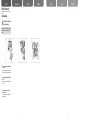
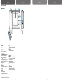
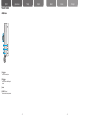
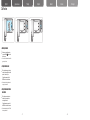
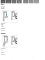
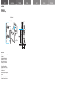
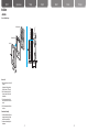
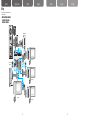
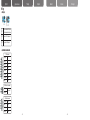
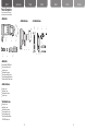
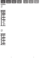
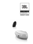
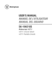
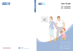
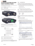
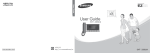
Home Network-Digital Door Lock User Guide GC68-01512A ED:01 Home Network-Digital Door Lock User Guide English This marking shown on the product or its literature, indicates that it should not be disposed with other household wastes at the end of its working life. To prevent possible harm to the environment or human health from uncontrolled waste disposal, please separate this from other types of wastes and recycle it responsibly to promote the sustainable reuse of material resources. Household users should contact either the retailer where they purchased this product, or their local government office, for details of where and how they can take this item for environmentally safe recycling. Business users should contact their supplier and check the terms and conditions of the purchase contract. This product should not be mixed with other commercial wastes for disposal. русский язык Türkiye Español Deutsch Italiano Português English Table of Contents русский язык Türkiye Español Deutsch Italiano Português Before You Read Precaution •Safety Precautions ............................................. 3 Chapter 1 - Preparation Parts and Functions •Video door phone ................................................ 9 •Interphone (option) ............................................ 13 Chapter 2 - How to Use Call Function •If a visitor comes to the front door and rings the bell....... 15 •Monitoring the outside........................................ 17 •Turning off the alarm sound .............................. 17 •Turning off the alarm sound if the door camera is stolen ... 17 •Talking with inter(sub) phone ............................ 19 •To call the security officer .................................. 23 •When the security officer calls you .................... 23 User Setup Functions •Selecting user setup mode ............................... 25 •Selecting melody ............................................... 25 •Adjusting melody volume .................................. 27 •Adjusting the talk volume/Screen ..................... 27 Chapter3 - Installation Installation •Video door phone .............................................. 29 •Door camera ...................................................... 31 Wiring •W hen connecting video door phone + 3 sub phones + door camera + lobby phone + interphone................. 33 •Setting up ........................................................... 35 •Specification of connection cables . .................. 37 Chapter4 - Useful Information Product Composition •Video door phone .............................................. 39 •Interphone .......................................................... 39 •Door camera ...................................................... 39 Troubleshooting •Frequently asked questions............................... 41 Product Specifications •Video door phone .............................................. 43 •Interphone .......................................................... 45 •Door camera ...................................................... 45 Product Specifications •Product Warranty ............................................... 47 -1 - -2 - English русский язык Safety Precautions Türkiye Español Deutsch Italiano Português *P lease first read the below to ensure the proper use of this product. ► Safety Precautions WARNING If instructions are not followed, this could result in serious injury or possible fatality to the user Do not install or disassemble on your own. - If the correct procedure is not followed, this could result in a malfunction, electric shock, or fire. Avoid the product from contact with other products that could emit heat, water, and humidity. - This may result in a fire or malfunction. Do not strike the product with hard objects. - The product may break or cause an electric shock or fire. Do not allow liquid to enter the inside of the product. -T here are dangers of electric shock or fire. -3 - -4 - English русский язык Safety Precautions Türkiye Español Deutsch Italiano Português *P lease first read the below to ensure the proper use of this product. ► Safety Precautions WARNING If instructions are not followed, this could result in serious injury or possible fatality to the user If there is an unusual smell, sound, or smoke coming from the product, turn off the power switch at the main electric switchboard and immediately contact the retailer. - This could result in electric shock or fire. Be careful not to splash water while cleaning the front door. - This could result in electric shock or fire. Do not press button with sharp objects, and do not insert objects through the hole. - This could result in electric shock or fire. Do not use a wet towel, flammable alcohol, benzene or thinners to clean the product. - This could result in electric shock or fire. ※ After a service, ensure that the service personnel performs a safety check-up. -5 - -6 - English Safety Precautions русский язык Türkiye Español Deutsch Italiano Português *P lease first read the below to ensure the proper use of this product. ► Safety Precautions Call the customer support center if you require assistance. If instructions are not followed, this could result in injury to the user, or potential damage to property. Do not hold onto the product or attempt to pull it out. - D o not allow a child to hang onto the product. The child may get hurt if the product falls down. Be careful while standing from below the product. - It may cause an injury if one's head knocks the product. Ensure any new operators read this manual prior to use. - It is important that all new operators read this manual immediately. -7 - -8 - Parts and Functions English русский язык ► Video door phone 1 2 Türkiye Español 3 4 5 6 7 8 9 ① Handset ② LCD Screen ③ POWER display lamp When the power supply is normal. ④ INTERPHONE[ ] button/display lamp Used to call the interphone(optional). ⑤ CALL [ ] button/display lamp Used to view outside or you can call the security officer by lifting the handset and pressing this button. ⑥ OPEN[ ] button Used to open the door while talking into the handset. ⑦ MODE button Used to change setups. (Ring tone, volume, brightness, default) ⑧ +/- button Used to adjust the volume and brightness. ⑨ POWER button Used to turn the power on or off. Reference Adjusting bell volume From the bell ringing mode, press the MODE button and adjust with +/- button. ● Adjusting the talk volume During the front door calling mode, press MODE button and use +/- button to adjust the options. ● Adjusting brightness While monitoring outside, press the MODE button and press +/- button to adjust brightness. ● ※ The sample color may vary from that of the photo image. -9 - - 10 - Deutsch Italiano - 11 - Português - 12 - English Parts and Functions русский язык Türkiye Español Deutsch Italiano Português ► Interphone (option) ① CALL[ ] button Used to call the video door phone. ② OPEN[ ] button Used to open the door while talking on the handset. ③ Handset ④ VOLUME (VOL) control Move the control switch to adjust the volume. - 13 - - 14 - English русский язык Call Function Türkiye Español Deutsch Italiano Português It is used to talk with the visitor or to open the door. ▶ If a visitor comes to the front door and rings the bell. The bell rings and the screen displays the visitor. ※ The bell will ring from the interphone (option). ※ The bell rings and the CALL lamp blinks. To talk with the visitor, pick up the handset and put it to your ear. ※You can call/talk by picking up the handset from the interphone. ※Screen will turn off automatically after about 30 seconds if the handset is not hung up. ※Maximum length of the front door call is 3 minutes, and maximum length of joint front door call is 1 minute. While talking, open the front door by pressing the OPEN[ ]button. ※ Door can be opened by pressing the OPEN[ ] button while talking over the handset from the interphone (option). Hang up the handset to end the call. ※ To end the call, you can put down the handset from the interphone (option). Reference • If the door lock system designed by our company is installed at the front door or joint front door, the door can be opened by pressing the OPEN[ ] button while you are talking on the handset. • To adjust the volume while calling, press the MODE button and use +/- button to control. - 15 - - 16 - English Call Function русский язык Türkiye Español Deutsch Italiano Português ► Monitoring the outside Outside screen view will appear when you press the CALL[ ] button from the stand-by screen. ※ The view outside of the front door will turn off after approximately 30 seconds. ► Turning off the alarm sound W hen the outside emergency detector is activated, the alarm will sound and will be reported to the security office. To stop the alarm, press and hold the MODE button for more than 2 seconds. ※This function is available only when the outside emergency detector is installed. ► Turning off the alarm sound if the door camera is stolen W hen the door camera is deviated or detached from the normal position, a warning bell is sounded. To stop the alarm sound, press and hold the MODE button for more than 2 seconds. ※This function is available only when SHT-CW610E has a tamper switch installed. - 17 - - 18 - English русский язык Call Function Türkiye Español Deutsch Italiano Português ► Talking with Inter(sub) phone To call inter(sub) phone from the video door phone While holding the handset, press the INTERPHONE[ ] button. ※ The bell rings and the INTERPHONE lamp blinks. Video door phone call melody rings at the inter(sub) phone. You can talk by lifting the inter(sub) phone's handset. Put down Inter(sub) phone 's handset to end the call. Reference • The interphone call will end automatically after about 30 seconds if someone does not answer. • Maximum length of the interphone call is 3 minutes. - 19 - - 20 - English Call Function русский язык Türkiye Español Deutsch Italiano Português ► Talking with inter(sub) phone To call the video door phone from inter(sub) phone While holding the handset, press the CALL[ ] button on the interphone or press the extension button on the sub phone. Interphone call melody rings at the video door phone. ※ The bell rings and INTERPHONE lamp blinks. You can talk by picking up the video door phone's handset. Put down inter(sub) phone's handset to end the call. Reference • The interphone call will end automatically after about 30 seconds if someone does not answer. • Maximum length of the interphone call is 3 minutes. - 21 - - 22 - English Call Function русский язык Türkiye Español Deutsch Italiano Português You can call the security officer or inter(sub) phone ► To call the security officer While holding the handset, press the ] button. CALL[ ※ Call bell rings from the handset. Talk when the security officer replies. ※ Put down the handset to end the conversation. ► When the security officer calls you The bell rings for an incoming security call. ※ The bell rings. Pick up the handset to talk. ※ Hang up the handset to end the conversation. - 23 - - 24 - English русский язык User Setup Functions Consumer OSD EXIT CAMERA MELODY SELECTOR : GUARD & LOBBY MELODY SELECTOR : INTERPHONE MELODY SELECTOR : MELODY VOLUME Türkiye Español Deutsch Italiano Português ► Selecting user setup mode rom the stand-by screen, press the F MODE button to select the option menu you want. ※ To end user setup mode, press the MODE button, select EXIT, then press the MODE button again or wait for 10 seconds for the automatic shut-down. ※ While calling or viewing the video door phone, press MODE button, select Call Volume, Color, Contrast, or Bright, and use +/- button to adjust. ► Selecting melody Select and set up melodies for the door camera, the lobby phone, the security phone or the inter(sub) phone. From the stand-by screen, press the MODE button, go to the CAMERA / INTERPHONE/ GUARD & LOBBY MELODY SELECTOR, and select melody using + or - buttons. •Selectable melodies 1~3 : Ding dong 1~3 4~9 : Melody 1~6 . To save the changes, press the MODE button ※ The same melody can be selected for more than one function. Namely the CAMERA, GUARD & LOBBY, and INTERPHONE. ※ To end the user setup mode, press the MODE button, select EXIT, then press the MODE button again or wait for 10 seconds for the automatic shut-down. - 25 - - 26 - English User Setup Functions русский язык Türkiye Español Deutsch Italiano Português ► Adjusting melody volume From the stand-by screen, press the MODE button, go to MELODY VOLUME, and press +/- button to adjust the volume. + : Volume increase – : Volume decrease o save the changes, press the MODE T button. ※ To end user option mode, press the MODE button, select EXIT, then press the MODE button again or wait for 10 seconds for the automatic shut-down. ► Adjusting the talk volume/Screen Either at the calling screen or while the video door phone is displaying, press the MODE button and select the setup option you want, and press +/- button to adjust the setting. • Talk volume Mode Talk Volume • Screen adjust mode Brightness Contrast Color To save the changes, press the MODE button. Reference •Melody and talk volume have 4 levels, and default level is 3. - 27 - - 28 - English Installation русский язык Türkiye Español Deutsch Italiano Português ▶ Video door phone Product installation Diagram Wall Mount Bracket Mount Bracket Screw Main Unit Video Door Phone Fixed Screw How to install 1. Select the area where you want to install the product. (Height would be 145cm high from the bottom to the center of LCD monitor) 2. Hold the wall mount bracket with the 4 screws to ensure the fixture is in the desired position. 3. Connect Door camera, lobby phone (including the connection to the security office) and interphone (option) cables to the video door phone. 4. Place the video door phone on the bracket, and use the screw to ensure the fixture is in place. 5. Turn on the power switch at the bottom of the product to see ensure the power is on. - 29 - - 30 - English русский язык Installation Türkiye Español Deutsch Italiano Português ▶ Door camera Camera installation diagram Mount Bracket Screw Wall Mount Bracket Main Unit How to install 1. Select the area where you want to install the product. (Height would be 145cm high from the bottom to the center of LCD monitor.) 2. Hold the wall mount bracket with the 4 screws to ensure the fixture is in the desired position. 3. Connect the connection cord with the video door phone to the door camera's terminal. 4. Check if it communicates with the video door phone. Precautions while installing 1. Avoid areas where direct sunlight, water, dangerous chemicals, or high-voltage cords, which can access the unit. 2. Avoid areas with extremely high or low temperatures. - 31 - - 32 - Wiring English русский язык Türkiye Español Deutsch Italiano Português * For the safety and the correct installation, please follow the instructions. ▶W hen connecting video door phone + 3 sub phones + door camera + lobby phone + interphone Door camera Lobby phone Sub phone 3 When used as the Main phone. When using 12~13 V po wer. wer. 14~24V po When using Sub phone 2 Main phone Sub phone 1 - 33 - - 34 - by phone English Wiring русский язык ► Setting up When using 12~13 V pow er. Türkiye Sub phone 3 Español Deutsch Italiano Português power. g 14~24V When usin Main phone ON JP 1 Sub phone 1 OFF It is on when used as the Main phone. / It is off when used as the Sub phone. Sub phone 2 JP 2 It is on when 12~13 V input is used. JP 3 It is on when 14~24V input is used. ► Specification of connection cables CN 7 connector 1 [White] Data 2 [Gray] VCC 3 [Pink] Video 4 [Blue] CH1-B 5 [Green] CH1-A 6 [Yellow] GND 7 [Orange] CH2-B 8 [Red] CH2-A Main phone Sub phone 1 CN 8 Door lock 1 connector 1 [Brown] 2 [Black] Door Lock 1 CN 6 Door 1 connector 1 [Orange] 12 V 2 [Red] Audio 3 [Brown] Video 4 [Black] GND - 35 - - 36 - English Wiring русский язык Türkiye Sub phone 1 Español Sub phone 2 Deutsch Italiano Português ► Specification of connection cables Slave 1 connector 1 [Yellow] GND 2 [Orange] Video Out (Master) 3 [Red] CH1-A 4 [Brown] CH1-B 5 [Black] Data Main phone Sub phone 1 Main phone Sub phone 1 Slave 2 / Slave 3 connector 1 [Yellow] GND 2 [Orange] Slave Video Out 3 [Red] Slave Voice A 4 [Brown] Slave Voice B 5 [Black] Slave Data Line CN 17 Sub Phone connector 1 [Orange] 12 V 2 [Red] Audio 3 [Brown] Call 4 [Black] GND CN 18 emergency detect connector 1 [Brown] SW In 2 [Black] GND Reference •Do not connect AC power. It may cause an electric shock or fire. - 37 - - 38 - 2 Pin for Camera Door Lock 1 EA 1 EA 1 EA 2 EA 2 EA 2 EA Wrench 2 EA (Onl Ext. Harness Ext. Harness 2 EA 2 EA Ext. Harness 2 EA 4 Pin for Door Camera 2 Pin for Camera Door Lock (Only for SHT-CP611E model) Wrench 2 EA EXT Harness EXT Harness 2 EA 2 EA Mount Bracket Screw 2 EA (Only for SHT-CP611E/EN model) (Only for SHT-CP611E/EN model) (Only SHT-CP611E/EN model) (Only for for SHT-CP611E/EN model) Mount Bracket 1 EA (Only for SHT-CP611E/EN model) (Only for SHT-CP611E/EN model) 4 Pin for Door Camera 4 Pin for Door Camera (Only for SHT-CP611E/EN model) (Only for SHT-CP611E/EN model) 2 Pin for Camera Door Lock Door Camera 1 EA Screw 1 EA Mount Bracket Screw 4 EA Ext. Harness 4 Pin Ext. Harness 4 Pin 1 EA 1 EA 2 Pin Camera Door Lock 2 Pin for for Camera Door Lock (Only SHT-CP611E/EN model) (Only for for SHT-CP611E/EN model) for Camera Door Lock (Only2forPinSHT-CP611E model) (Only for SHT-CP611E model) Ext. Harness 4 Pin for Door Camera 4 Pin for Door Camera 4 Pin for Door Camera 4 Pin for Door Camera Door Camera Mount Bracket 2Mount Wrench Mount Bracket Screw Wrench Door Camera Mount Bracket Bracket Screw Pin for Camera Door Lock 1 EA 1 EA 2 EA 2 EA (Only 2 EA 1 EA 1 EA 2 EA 2 Pinfor forSHT-CP611E Camera Doormodel) Lock (Only for SHT-CP611E model) Wrench Ext. Harness Mount Bracket 4 Pin for DoorScrew Camera 4 Pin for Door Camera 2 EA EA 2 EA Screw Wrench Ext. 2Harness Mount Bracket 2 EA 2 EA 2 EA 2 Pin for Camera Door Lock 2 Pin formodel) Camera Door Lock (Only for SHT-CP611E (Only for SHT-CP611E model) Português EXT 2 EAHarness 2 EA Screw Screw 1 EA 1 EA Mount Bracket Mount Bracket Screw Wrench Mount Screw 2 Wrench EA 1 EA Bracket Mount2 Bracket EA 1 EA 2 EA 2 EA Screw 1 EA Mount Bracket 1 EA Mount Bracket 1 EA Door Camera 1 EA Door Camera Door 1 EACamera 1 EA 4 Pin for Door Camera Wrench Door Camera Mount Bracket Mount Bracket Screw Pin Camera -Mount 39 - Bracket Pin for Door Camera 444Pin 4 4Pin forforDoor 4Door PinCamera for Door Camera Pinfor forDoor DoorCamera Camera Door Camera Mount Bracket Screw 1 EA EXT Harness EXT Harness 2 EA 2 EA EXT Harness EA EXT2Harness 2 EA Italiano 2 Pin for Camera Door Lock Pin for Camera Door Lock (Only for2 SHT-CP611E/EN model) (Only for SHT-CP611E/EN model) 4 Pin Door Camera EXT Harness 4 Pin for for Door Camera Mount Bracket 4 EA Mount Bracket 1 EA 4 Pin for Door Camera 4 Pin for Door Camera Screw 1 EA Interphone 1 EA Mount Bracket Screw 4 EA Door Camera Mount Bracket Mount Bracket Screw Screw Door Camera Mount Bracket Mount Bracket Screw 1 EA 4 EA 4 EA 1 EA 1 EA 4 EA 4 EA Door Camera EA Door1Camera 1 EA EXT Harness 2 EA 2 Pin for Camera Door Lock (Only for SHT-CP611E/EN model) 4 Pin for Door Camera EXT Harness 3 EA Ext. Harness 4 Pin 1 EA 4 Pin for Sub Phone 8 Pin for Multi Lobby phone with Guide station Screw 1 EA Screw 1 EA Deutsch 4 Pin for Door Camera 4 Pin for Door Camera 4 Pin for Door Camera for Camera Door Lock Mount Bracket 2 Pin Mount Bracket Screw Mount Bracket Mount Bracket Screw (Only for for SHT-CP611E/EN model) 2 Pin Camera4Door 4 EA EALock 4 EA 4 EA (Only for SHT-CP611E/EN model) 4 EA Screw Mount Bracket 4 EA Monitor(SHT-3306BM) Monitor(SHT-3306BM) Monitor(SHT-3306BM) Monitor(SHT-3306BM) Monitor(SHT-3306BM) Monitor(SHT-3306BM) 1 EA 11EA EA 1 EA 11EA EA Screw 2 EA Mount Bracket 1 EA Monitor(SHT-3306BM) 1 EA 4 EA Mount Bracket 4 EA Interphone Ext. Harness 4 Pin 4 Pin Mount Bracket Mount Bracket Screw Ext. Interphone Ext. Harness Mount Mount Bracket Mount Bracket Screw phone Harness Pin Mount Mount Bracket Screw Interphone Ext. Harness 4 Pin 4 Pin Bracket Mount Bracket Screw Screw44Ext. phone Interphone Ext. Harness PinHarness Mount Bracket BracketMount Mount BracketMount ScrewBracket : 1 EA piece1Bracket 1 EA 1Door 1 EA 1 EA 2 EA 2 EA EA 1camera EA 1 EA 22 EA EA 1 EA EA 11 EA 1 EA 1 EA 1 EA 2 EA 2 EA 11 EA EA EA EA EA Mount Bracket : 1 piece Mount Bracket Screw : 4 pieces Door camera fixed Screw : 1 piece 4-pin cable for Door camera : 1peice / 2-pin cable for Camera Door Lock (only for SHT-CP611E/EN model) : 1 piece User Manual 1 EA Screw Screw 1 EA Screw Screw Screw 1 EA Screw 1 EA 1 EA 11EA 1 EA 1 EA EA Mount Bracket Mount Bracket Screw 4 Pin for Sub Phone Door Camera Door Camera Door Camera EA Door1Camera 1 EA Mount Bracket 1 EA 2 EA Door Camera Mount Bracket Mount Bracket Screw Bracket Screw Screw Door Mount Mount Screw 1 EACamera 4 EA Bracket 4 EA 1 EA 1 EA 4 EA 4 EA 1 EA 4 Pin for Door Camera Monitor(SHT-3306BM) 1 EA ▶ Door camera (SHT-CP611E: Option) 2 Pin for Camera Door Lock 2 Pin for Camera (Only for SHT-CP611E/EN model) Door Lock (Only for SHT-CP611E/EN model) (Only for SHT-CP611E/EN model) Interphone : 1 piece Mount Bracket : 1 piece Mount Bracket Screw : 2 pieces 4-pin cable : 1 piece 4 Pin for Door Camera ▶ Interphone (SHT-IPE101: Option) Ext. Harness 4 Pin Mount Bracket Mount Bracket Screw Ext. Harness 4 Pin Mount Bracket Mount Bracket Screw 1 EA 1 EA 2 EA 1 EA 1 EA 2 EA Ext. Harness 4 Pin 1 EA 2 Pin for Camera Door Lock (Only for SHT-CP611E/EN model) Video door phone(SHT-3006BM) : 1 piece Video door phone Bracket : 1 piece User Manual : 1 piece Mount Bracket Screw : 4 pieces Video door phone fixed Screw : 2 pieces 8-pin cable for Lobby phone with Guide Station : 1 piece / 4-pin cable for sub phone EXT Harness : 2 pieces EXT Harness 2 EA 4 Pin for Door Camera 2 Pin for Camera Door Lock (Only for SHT-CP611E model) Ext. Harness 2 EA ▶ Video door phone Monitor(SHT-3306BM) Mount Bracket Screw Monitor(SHT-3306BM) Mount Screw 1Bracket EA 2 EA1 EA Ext. Harness 4 Pin Mount Bracket Mount Bracket Screw ▶ Door camera (SHT-CP611E: Option) 1 EA 4 Pin 1 EA 2 EA Screw Ext. Harness Mount Bracket Mount Bracket 1 EA 1 EA 2 EA EXT Harness 3 EA Screw 1 EA Wrench 2 EA Interphone Interphone 8 Pin for Multi Lobby phone 1 EA Pin Lobby phone Pin for Multi Lobby phone 888Pin 4 Pin phone for Sub Phone 8 8phone Pin forforMulti 8Multi PinLobby for Multi phone Lobby Pinfor forMulti MultiLobby Lobby phone 4 Pin for Sub Phone 4 Pin for Sub Phone 4 Pin for Sub Phone 4 Pin for Sub 4 Pin Phone for Sub Phone 1 EA with Guide with station 4station Pin for Sub Phone Guide with Guide station with Guide station with Guide with station Guide station with Guide station Mount Bracket Screw Screw Screw Screw Mount Bracket Bracket Screw Mount Bracket ScrewScrew Screw Screw Screw BracketMount ScrewBracket Screw EXT Harness 3 EA 3 EA 4 EA 4 EA 2 EA 2 EA Harness EXT EA EXT Harness 3 EA 3 EA 44EA 4 EA 4 EA 22EA 2 EA 2 EA EXTHarness Harness3EXT 3EXT EAHarness EA EA Mount Bracket Mount Bracket 1 EA 1 EA 8 Pin for Multi Lobby phone with Guide station User Manual 1 EA 1 EA User Manual UserManual Manual User User Manual UserManual Manual User 1 EA 1 EA 11EA 1 EA 1 EA EA 1 EA Screw 2 EA Interphone Mount Bracket Screw 2 EA Mount Bracket Screw 2 EA Mount Bracket Monitor(SHT-3306BM) MountBracket BracketBracket Monitor(SHT-3306BM) Mount Mount onitor(SHT-3306BM) MountBracket BracketMount Monitor(SHT-3306BM) Monitor(SHT-3306BM) onitor(SHT-3306BM) 1 EA 1 1 EA 1 EA EA 1 EA 11EA 1 EA 11EA EA 1 EA 1 EA EA Ext. Harness 4 Pin Mount Bracket Mount Bracket Screw Screw Ext.1Harness 4 Pin Mount Mount2 Bracket Screw EA 1 EA Bracket EA Screw 1 EA Español 1 EA 1 EA 2 EA 1 EA Interphone Interphone 1 EA 1 EA ▶ Interphone (SHT-IPE101: Option) 1 EA Interphone Mount Bracket Screw 4 EA ▶ Video door phone Türkiye Mount Bracket Screw 2 EA This is the product composition. Before you begin, please make sure that you have all parts listed below. 4 Pin for Sub Phone EXT Harness 3 EA 1Interphone EA EXT Harness 3 EA Mount Bracket 1 EA Mount Bracket 1 EA Mount Bracket 4 EA Product Composition with Guide station with Guide station Interphone Screw 2 EA nitor(SHT-3306BM) 1 EA русский язык Screw 2 EA racket Screw 4 EA hone A mera A amera EA English Mount Bracket Screw Mount Bracket Screw 4 EA 4 EA Ext. 2 EAHarness 2 EA 2 Pin Camera Door Lock 2 Pin for for Camera Door Lock (Only SHT-CP611E model) (Only for for SHT-CP611E model) Ext. Harness Ext. Harness 2 EA 2 EA - 40 - English Troubleshooting русский язык Türkiye Español Deutsch Italiano Português ▶ Frequently asked questions The power is not turning on. ● Check if the power cable is connected. The screen is too dark. ● Check the lights around the cameras installed outside. ● Clean up the camera installed outside. ● Adjust the brightness on the function setup (Refer to page 27) ● Out of 4 levels, level 3 is the default, and as the level increases, the screen gets brighter. Noise is too loud when I talk. ● Check if the audio line among the door phone lines is short circuited. I cannot hear my guest's voice properly. ● Check the volume status. ● Check the wire connection between the video door phone and the door camera. - 41 - - 42 - English Product Specifications русский язык Türkiye Español Deutsch Italiano Português ► Video door phone ◆ SHT-3006 BM Device Specifications Categories Input Power Provided by the distributor installed between floors. Maximum Power Consumption. 10 W DC Input Voltage 12V~24V Handset call type. Call Method Size of the Monitor Screen 6 inches LCD Resolution (Resolution: dot) SHT3006BM 480(Horizontal) X 234(Vertical) LCD Screen View Angle Horizontal angle ±50° , Vertical angle +50°/-30° LCD Back-light Lifespan 10,000 hrs (when used in +25°) Method of Transferring US : NTSC(Composite) / Video Signal EN : PAL(Composite) Video Cable Wiring 2-line wiring Camera Range Diameter: 0.65mm / Suggested Range: within 30m Door Phone Ring Tone Refer to page 25. Weight (main body) 0.86 Kg/1.9 lb Size (Width X Height X Depth) 278.0 mm x 130.0 mm x 37.0 mm 10.9 inch x 5.1 inch x 1.5 inch - 43 - - 44 - English Product Specifications русский язык Türkiye Español Deutsch Italiano Português ► Interphone ◆ SHT-IPE101 Device Categories Specifications Communication Mode Handset Communication Provided by the monitor Chime Melody Main Unit Electricity Consumption SHT-IPE100 Weight SHT-IPE101 Max. 150 mA SHT-IPE100 : 440 g (0.97 lb), SHT-IPE101 : 500 g (1.1 lb) SHT-IPE100 : 99 mm x 217.5 mm x 59.8 mm Dimension (W x H x D) (3.9 inch x 8.6 inch x 2.4 inch) SHT-IPE101 : 98.5 mm x 214 mm x 54.8 mm (3.9 inch x 8.4 inch x 2.2 inch) ► Door camera ◆ SHT-CP611E Device Categories Input Power Specifications DC 12 V (Provided by the monitor) Injection Method of US : NTSC(Composite) / EN : PAL(Composite) Video Signal SHT-CP611E 74.5 mm x 135.5 mm x 10.4 mm Size (Width X Height X Depth) (2.9 inch x 5.4 inch x 0.4 inch): Mount Bracket included 180g (0.4lb) Weight - 45 - - 46 - English Product Warranty русский язык Türkiye Español Deutsch Italiano Português ► Product Warranty Seoul Commtech Products are supplied with one(1) year warranty base from the date of purchase, we’ll repair or replace the defective product with a new or factory rebuilt replacement. Subject of Warranty 1. This warranty applies to the original purchase only. 2. All warranty will be invalid if unauthorized repair or modifications are made to the unit or in any case of accident, misuse, damage caused by improper installation and altered serial numbers. 3. If you need a warranty service, you should consult with the customer support center or the dealer office. The product in all cases must be accompanied by the following items; customer name, address, telephone number, the serial numbers, copy of customer sales receipt showing the purchase date and place. The model number is on the box and front of the manual. The serial number is on the unit. Record the model and serial numbers in the spaces provided below. Refer to these numbers for warranty service. Model No. Serial No. - 47 - - 48 -