1
■ THREE PHASE POWER QUALITY ANALYSER
ENGLISH
User's manual
1
C.A 8332B
C.A 8334B
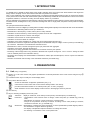
MEANING OF SYMBOLS USED IN THE INSTRUMENT
: WARNING ! Please refer to the User's Manual before using the instrument.
In this User's Manual, the instructions preceded by the above symbol, should they not be carried out as shown, can
result in a physical accident or damage the instrument and the installation.
: Earth
: Double insulation
: Conform to WEEE 2002/96/EC standard
Thank you for acquiring a C.A 8332B or C.A 8334B three phase power quality analyser.
To obtain the best possible service from your instrument :
■ read these operating instructions carefully,
■ comply with the precautions for use.
PRECAUTIONS FOR USE
■ Read carefully all the notes preceded by
symbol.
■ If you don't use this instrument according the user's manual, you can compromise the safety, and you can go in dangerous
situation.
■ The safety of all the system which include this instrument is the system owner responsability.
■ For your safety, use only tests leads delivered with the instrument : they are conform to EN 61010-031 (2002) standard.
■ Before each use, check the good state of test leads.
■ For your safety, use only accessories delivered with the instrument or approuved by the supplier.
■ Respect the climatic conditions for use (see § 6).
■ This instrument can be used on category-IV installations for voltages not exceeding 600V (AC or DC) in relation to the earth
(as per EN 60664-1).
■ The use of accessorie (sensor) with lower category (CAT III for example) reduce the set use (Instrument with sensor) at this
category (CAT IV begin CAT III for example).
■ Ensure the measurement leads and sensors are disconnected before removing the battery.
■ Use battery packs supplied by the maker.
INSTALLATION CATEGORIES
Definition of installation categories (cf IEC 664-1 publication) :
CAT III :
CAT III circuits are power supply circuits that can support major transient overvoltage.
Example : industrial unit or machine power supply.
CAT IV :
CAT IV circuits can support very hight transient overvoltage.
Exemple : power input.
WARRANTY
Our guarantee is applicable for three years after the date on which the equipment is made available (extract from our General
Conditions of Sale, available on request).
2
CONTENTS
1. INTRODUCTION ....................................................................................................................................................................... 4
2. PRESENTATION ....................................................................................................................................................................... 4
2.1
Unit .............................................................................................................................................................................. 4
2.2
Display ......................................................................................................................................................................... 5
2.3
Presentation of the different battery states .................................................................................................................. 6
3. INITIAL OPERATION ................................................................................................................................................................ 7
3.1
Configuration of the instrument
........................................................................................................................... 7
4. DISPLAY MODES ................................................................................................................................................................... 12
4.1
Waveforms Mode
............................................................................................................................................ 12
4.2
Harmonics Mode
............................................................................................................................................ 15
4.3
Power / Energy Mode
4.4
Transient mode
4.5
Alarms Mode
4.6
Recording Mode
4.7
Screen Memorisation
4.8
Printing
4.9
Help
4.10
Logiciel "QualistarView" ............................................................................................................................................ 26
........................................................................................................................................ 17
(on C.A 8334B only) ............................................................................................................. 19
........................................................................................................................................................ 21
............................................................................................................................................... 22
.................................................................................................................................... 25
.............................................................................................................................................................. 26
................................................................................................................................................................... 26
5. GENERAL SPECIFICATIONS ................................................................................................................................................ 27
5.1
Dimensions and weight ............................................................................................................................................ 27
5.2
Power supply ............................................................................................................................................................. 27
5.3
Climatic conditions .................................................................................................................................................... 27
5.4
Compliance with international standards ................................................................................................................. 27
6. FUNCTIONAL CHARACTERISTICS ..................................................................................................................................... 28
6.1
Reference conditions ................................................................................................................................................ 28
6.2
Electrical specifications ............................................................................................................................................. 28
6.3
Specifications of the sensors (with C.A 8332B/34B) ................................................................................................ 32
7. MAINTENANCE ..................................................................................................................................................................... 37
7.1
Recharging the battery .............................................................................................................................................. 37
7.2
Cleaning the housing ................................................................................................................................................ 37
7.3
Calibration testing ..................................................................................................................................................... 37
7.4
Repairs ...................................................................................................................................................................... 37
8. TO ORDER .............................................................................................................................................................................. 38
9. APPENDIX .............................................................................................................................................................................. 40
9.1
Front view of the instrument ...................................................................................................................................... 40
9.2
Mathematical formulae used to compute the various parameters ........................................................................... 41
9.3
Setup DPU 414 printer .............................................................................................................................................. 47
3
1. INTRODUCTION
C.A 8332B and C.A 8334B are three phase power quality analysers which are compact and shock-resistant. Their ergonomic
design and the simplicity of their user interface make their use pleasant and intuitive.
They not only enable the user to obtain an instant image of a network’s principal characteristics but also to monitor their variation
over a period of time. Their multi-task measurement system simultaneously handles all the measurement functions of the various
magnitudes, detection, continuous recording: and their display without any constraints.
They are intended for the technicians and engineers of the test and maintenance teams working in industry and the administration,
for measurements, enabling them to carry out checks and diagnostic work on single phase, two phase or three phase low voltage
networks.
The principal measurements made are:
- Measurement of AC rms voltages up to 480V (phase-to-neutral) or 960V (phase-to-phase) for two-wire, three-wire or four-wire networks.
- Measurement of alternating RMS currents up to 6500A rms.
- Measurement of the frequency of 50Hz, 60Hz (10Hz to 70Hz) networks.
- Calculation of neutral current by vector summing of phase current for star configurations.
- Calculation of peak factors for currents and voltages.
- Calculation of the K factor for currents (transformers).
- Calculation of short-term flicker for voltages.
- Calculation of the phase unbalance for voltage and current (three-phase networks only).
- Measurement of harmonic angles and rates (with respect to fundamental value) for voltage, current or power (C.A 8334B only),
up to level 50. Calculation of overall harmonic distortion factors.
- Measurement of active, reactive and apparent power per phase and their aggregate.
Calculation of the power, shift and tangent factor .
Total amount of energy generated and received from a moment chosen by the operator.
- Monitoring of the average value of any parameter, calculated over a period running from 1 sec to 2 hours. Storage of values
over an unlimited period in the instrument memory.
- Recording, time stamping and characterisation of disturbance: Swells, dips and interruptions, overrun of power and harmonic
thresholds...
- Detection of transients and recording of the associated waveforms (C.A 8334B only).
2. PRESENTATION
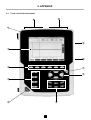
2.1 Unit (see § 9. Appendix)
➀ Display on a LCD colour screen with graphic representation of network parameters in the mode chosen using the keys ➄
➁
➂
(see § 2.2).
6 variable function keys to modify the current display mode
4 keys which allow the user to:
access the instrument configuration parameters (see § 3.1)
memorise the current screen and access screens already stored in the memory
print the measurement results on an external printer (see “To order” paragraph)
obtain assistance on the current display mode functions in the language chosen by the user
➃
➄
ON / OFF key
Keys for choosing the display mode at any time:
Transients:
display of waveforms, motor startup current (Inrush) and interruption (C.A 8334B only).
Harmonics:
- representation of the harmonic ratios of voltage, current and power (C.A 8334B only), order by
order,
- determination of harmonic current produced by non-linear loads,
- analysis of the problems caused by harmonics according to their order (heating of neutrals,
conductors and motors, etc.) (C.A 8334B only)
Waveforms : representation of voltage and current waveforms or vector representation (Fresnel diagram) used for:
- the identification of signal distortion signatures,
- the display of amplitude and phase unbalance for voltage and current
- the checking of connections in the correct phase order
4
Power / Energy: - the display of power levels and the associated parameters (power factor, displacement and
tangent),
- energy metering,
- Four quadrants measurement to discern produced /consumed active energies and inductive /
capacitive reactive energies.
Recording: - time-related representation as bar charts or curves, of mean power levels or of the mean value of
any other parameter,
- mains voltage stability check,
- management of power consumed and generated (most economical choice with energy distributor),
- monitoring of harmonic variations,
Alarms:
- a list of the alarms recorded according to the thresholds programmed during configuration,
- logging of supply network interruption with half-period resolution (Vrms, Arms, Urms),
- determination of energy consumption overruns,
- checking of compliance with energy supply quality contract.
➅
➆
➇
➈
➉
4 keys:
11
3 current inputs on the top of the instrument to enable the use of ammeter sensors (MN clamp, C clamp, AmpFLEX, PAC
clamp.)
12
Protective case
and
which enable movement of the cursor, browsing or the selection of data.
Validation key
Network supply connector
IR RS232 bidirectional optical output for transferring data to a PC (bidirectional) or printing to a dedicated printer (DPU 414 - SEIKO).
4 voltage inputs situated on the top of the instrument
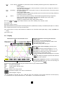
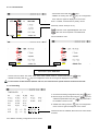
2.2 Display
Measurement values associated with curves
Important parameters concerning the instrument:
- Display mode
- The frequency of the measured network
- The proportion of memory occupied for certain modes
- The current date and time
- The battery charge status (see § 2.3)
Selection of the curves to display by pressing on the
keys
:
- 3U displays the three compound voltages U12, U23, U31,
- 3V displays the 3 phase-to-phase voltages V1N, V2N, V3N,
- 3A displays the three phase currents and 4A with the
neutral current of a three-phase system,
- L1, L2 or L3 display the current and voltage in turn on phase
1, 2 or 3.
Nota : the stability of the display requires the first measured
magnitude of each selection.
Instant values of signals at an instant “t”, at the intersection
of the cursor and the curves. The cursor is moved along the
.
time scale with the keys
Selection of the measurement type using the variable function keys
RMS
True RMS measurement
THD
Overall harmonic distortion factor
CF
Crest factor
➁, situated below the screen:
max/min Extreme and average values
Simultaneous display of the various measurements
Fresnel diagram of signals
The calculation of the DPF, Tan, KF, φ, UNB, Min, Max, VAR, Harmonics, PST, and DF parameters and the frequency
measurement can only be performed if Ch 1, with voltage V1, is connected to the network.
5
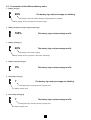
2.3 Presentation of the different battery states
1. Battery charging
20%
The battery sign and percentage are blinking
Percentage of the total capacity already charged (between 0 and 99%)
Battery capacity level in proportion to the actual charge
2. Battery full (End of charge or begin of discharge
100%
The battery sign and percentage are fix
3. Battery discharging
20%
The battery sign and percentage are fix
Percentage of the remain capacity
Battery capacity level in proportion to the remain percentage
4. Battery empty discharging
0%
The battery sign and percentage are fix
5. New battery charging
?
The battery sign and percentage are blinking
Interrogative point showing unknown capacity level
Fix battery capacity level
6. New battery discharging
?
The battery sign and percentage are fix
Interrogative point showing unknown capacity level
Fix battery capacity level
6
3. INITIAL OPERATION
The instrument is initially started up by pressing on the
its serial number.
key, the startup screen indicates the instrument software version and
If there is no AC mains supply, the instrument can operate with batteries only, provided they are correctly charged.
The instrument’s batteries are charged when it is connected to the AC mains supply.
Note: When the equipment is stopped using the
recording.
key, a confirmation is requested if the equipment is in the process of
3.1 Configuration of the instrument
The instrument must be configured the first time it is used and then whenever necessary. The configuration is saved in the
non-volatile memory when the instrument is switched off (with
When the
key).
key is pressed, the following choices appear:
- Choose the language used with the variable function keys
- Select the other configuration settings with the
➁, situated just below the screen.
keys
- Validate with the key
The settings available are presented in the following paragraphs.
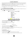
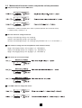
3.1.1 Date / Time
10/10/2000 16:45
- Select the number to be modified with the
- Modify the value of the number selected with the
- Validate the setting with the
keys, it will appear in bold type.
keys
key, the Configuration menu will once again be displayed on the screen.
Note: The time and date systems may be chosen by the user.
3.1.2 Light / Contrast
Two bargraphs appear in this display
- Choose Light or Contrast with the
- The setting is chosen with the
- Validate the setting with the
keys
keys and the setting level indicated on the bargraph.
key, the Configuration menu will once again be displayed on the screen.
7
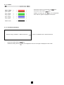
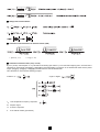
3.1.3 Colours
- Choose the channel concerned with the
- Choose the colour with the
- Validate the setting with the
keys
keys
key, the Configuration
menu will once again be displayed on the screen.
3.1.4 Calculation parameters
Reactive energy calculation < Without harmonics >
-
Choose the method with the
-
Validate the setting with the
Choice of calculation with or without harmonics
keys
key, the Configuration menu will once again be displayed on the screen.
8
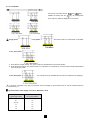
3.1.5 Connection
- Choose the connection with the
Validate the setting with the
and
keys
key, the Configuration
menu will once again be displayed on the screen.
Single phase
or two-phase
3-wire, three phase
, the neutral current is not measured or calculated.
:
1. Three phase, triangle network: only power totals are representative of the actual situation
2. Three-phase star network: the neutral current is not calculated. It is necessary to connect neutral to obtain representative
power levels per phase.
4-wire three-phase
: the neutral current is calculated and its value and waveform are displayed.
V1 must be connected in any type of connection since the display is synchronised from V1 and the network frequency
measured by V1.
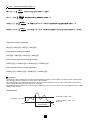
■ Synchronisation of the display of curves in “Waveform” mode
Display selection
(vertical right menu)
Reference channel
for synchronisation
3U
U1
3V
V1
4A / 3A
A1
L1
V1
L2
V2
L3
V3
9
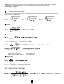
3.1.6 Current sensor
- Choose the sensor with the
keys
- Validate the setting with the
key, the Configuration
menu will once again be displayed on the screen.
From 1 to 2999A, nominal value of primary current
Secondary current value (5A or 1A)
make the cursor appear/disappear and move.
allow the current required to be determined.
Current transducer ratio
3.1.7 Communication
Transmission speed 57600 BDS
- Choose from the values: 300, 2400, 4800, 9600, 19200, 38400, 57600 or 115200 bauds with the
- Validate the setting with the
keys
key, the Configuration menu will once again be displayed on the screen.
For the transfer of data between Qualistar and a PC, the communication speeds must be identical at both ends.
3.1.8 Recording
1. Choose the recording configuration using the
2. Move through the chosen field using the
validate the parameters using the
be modified is shown in bold
3. Validate the setting with the
keys
keys and
keys; the field to
key, the Configuration
menu will once again be displayed on the screen.
If these lines are not validated, all the harmonic orders will be
recorded.
Four different recording configurations can be stored
10
3.1.9 Alarm
A programmed alarm must be set to ON to be taken into account (general activation or deactivation of alarms is generated in
mode).
■ Alarm programming
Choose the parameters associated with an alarm from the parameters proposed; phases survey, threshold value and minimum
duration filtering can be programmed
NB: The programmed hysteresis is common to all alarms.
Hysteresis (see §9.2)
< or >
Threshold value
Alarm activation
Minimum duration from
beginning threshold
detection to store the alarm
3L : capture of each 3 phases
N : Neutral capture
Σ : Total power capture
Σ/3: Average value of threephase capture
Browser column
Capture parameter
1. Select the modifiable field using the
keys.
2. Activate or adjust the threshold values using the
3. Validate the setting with the
keys; the field to be modified appears in bold
key, the Configuration menu will once again be displayed on the screen.
NB : When an alarm is "OFF":
1) The parameters previously used are kept in the memory and reappear if the alarm is selected again.
2) To move quickly from one programmed alarm to another:
simply position the cursor on the alarm numbers column and use
.
Modifying one or several characteristics of an alarm set to ON switches it automatically to OFF.
NOTA : Only alarms on VRMS, URMS and ARMS (except for neutral current) can be programmed with a minimum threshold overrun
duration of up to 1/100s.
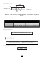
3.1.10 Recorded data delete
When data delete is selected, the following question is displayed:
Are you sure you want to delete all the data?
Yes
- Choose the relevant answer with the
- Validate the setting with the
No
keys
key
When the data is deleted, the instrument configuration returns to the default setting (maker’s configuration) and the following are
deleted:
- all detected alarms,
- all screen photos taken,
- all the captured transient states (on C.A 8334B only),
- and all recordings made.
The instrument will automatically switch itself off once the data have been deleted.
3.1.11 Rated frequency
Rated frequency of network: 50 Hz or 60 Hz
This parameter determines the correction coefficients used for calculating power and energy, with AmpFlex sensor.
- Choose the rated frequency using the
- Validate the adjustment using the
keys
key: the screen displays the “Configuration” menu again.
11
4. DISPLAY MODES
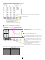
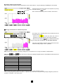
4.1 Waveforms Mode
- Press on the display mode key
- The following screen is displayed:
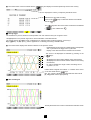
■ Measurement of rms voltage on a three phase system:
Values measured for each curve every second (same colour),
according to the measurement type chosen with the variable
function keys ➁, situated directly below the screen.
The curves to be displayed are selected by pressing on the
keys:
- 3U displays the three phase-phase voltages of a three
phase system,
- 3V displays the three single voltages of a three phase
system,
- 3A displays the three phase currents of a three-wire, three
phase system,
The neutral current is not a direct measurement but
the resulting total of the 3 currents measured.
- L1, L2 and L3 respectively display the current and voltage
on phases 1, 2 and 3.
Instant values of signals at an instant “t”, at the intersection of
the cursor and the curves. The cursor is moved along the time
keys.
scale with the
The measurement type is selected using the variable function keys
All these measurements are valid in 3U, 3V, 3A, L1, L2, L3
➁, located beneath the screen.
Important: The choice of curves to be displayed (
keys) depends on the type of connection (see § 3.1.5):
- 4-wire, three phase: 3U, 3V, 4A, L1, L2, L3
- 3-wire, three phase: 3U, 3V, 3A, L1, L2, L3
- Two-phase: 2V, 3A, L1, L2
- Single phase: No choice (L1)
This comment is valid for all display modes.
■ Measurement of phase to phase RMS voltages on the 3 phases
Selection of 3 V
12
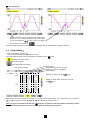
■ Measurement of RMS current on the 3 phases and the neutral of a 4-wire three phase system
Selection of 4 A
■ Measurement of overall harmonic distortion factors for voltage
Measurement of the crest factor
■ Measurement of extreme and average current values
Select with
3 V or 4 A to obtain the Min, AVG, Max,
peak + or peak – values for current or voltage (see §9.2)
Peak values refreshed every 250ms but calculated every second.
Max and Min values are measured from the power on or the last
key pressed
Nota : The Max and Min measurements are calculated every half period (e.g. : every 10ms for a 50Hz signal). The Avg
measurements are calculated every second. However, the Max, Avg and Min measurements are refreshed every 250ms.
13
■ Simultaneous display of all the different current measurements
Summary of RMS, DC, THD, CF and KF parameters
Calculation of the K factor for transformer downgrade
Distortion factor
Note: The K factor only concerns current.
Similarly, the flicker value only concerns voltage.
3V → PST, flicker calculated on short term
3A and 4A → KF factor
L1, L2 and L3 flicker and KF factor
DC current values only for the PAC 93 clamp
■ Display of the Fresnel diagram or vector diagram
Absolute value or modulus of voltage of current at
fundamental frequency.
Select the Fresnel diagram display choice
Φ12 corresponds to the phase shift of channel 1 compared
to 2
Φ23 corresponds to the phase shift of channel 2 compared
to 3
Φ31 corresponds to the phase shift of channel 3 compared
to 1
NB: This is valid for current (4A and 3A) and for single
voltage (3V).
When the user chooses to look at a specific phase (L1, L2
or L3) ΦVA is the phase angle of V in relation to A.
Current unbalanced ratio:
For this 3 V selection, it is the voltage unbalanced value.
On each phase L1, L2, L3: display of Vn and An on a Fresnel diagram.
Display Filter
(RH vertical menu)
3U
3V / 2V
4A / 3A / 2A
L1
L2
L3
Reference vector for the
Fresnel diagram
U1
V1
A1
A1
A2
A3
14
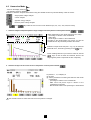
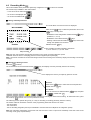
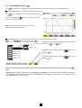
4.2 Harmonics Mode
- Press on the display mode key
- The following screen is displayed:
Selection of harmonic analysis measurement using the variable function keys located directly under the screen:
Single phase voltage analysis
current analysis
apparent energy analysis
Phase to phase voltage analysis
The
and
keys allow the user to zoom in both directions (2%, 5%, 10%, 20%, 50% and 100%)
1. Harmonic analysis of the phase-phase or single voltages of the three phases of a three phase network
or
Values measured for each phase (harmonic N°3: Vh03):
- Percentage in relation to the fundamental
- RMS value,
- Phase angle in relation to the fundamental,
according to the measurement type chosen (V) with the
variable function keys situated just below the screen.
Selection of expert mode -0+ (see 4. in § 4.2), for the three
phases 3L or L1, L2 or L3 by pressing on the
keys.
Cursor enabling selection up to harmonic order 50, with the
keys, as soon as order 25 is reached, the 25 to 50
range appears (order 0 represents the DC component).
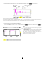
2. Harmonic analysis of the current of one of the phases of a three phase network
On phases L1, L2, L3 display of:
■ the THD,
■ and the parameters concerning the harmonic order under
consideration:
- percentage in relation to the fundamental
- RMS value and phase angle in relation to the
fundamental component
- MIN and MAX values of the percentage to fundamental
Min and Max values are reset each time the cursor position is changed.
15
3. Harmonic analysis of the power of one of the phases of a three phase network
(C.A 8334B only).
The bars representing the harmonics have signs.
Since the bar selected is negative, pictogram G indicates that it is a harmonic emitted (by convention, positive harmonics are
received and negative harmonics emitted). The sign is only available in harmonic power measurement.
4. Harmonic analysis in expert mode (C.A 8334B only)
Press on the
key to select “-.+” and on the variable function key
; the following is displayed (ditto for
):
Note:
- in the first column, the harmonics inducing a negative
sequence are indicated,
- in the second column, those inducing a nil sequence (added
into the neutral)
- in the third column, those inducing a positive sequence.
The influence of harmonics on heating of the neutral or on
rotating machines can thus be analysed.
Expert function is possible in V and A
16
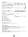
4.3 Power / Energy Mode
- Press on the display mode key
The instrument enables:
- Active energy measurement : produced and consumed (negative and positive)
- Measurement of reactive power: capacitive or inductive
- Measurement of apparent power:
- To start energy aggregation, press
, the date and time appear on the top, left of the screen
- To stop energy aggregation, press
, the date and time appear on the top, right of the screen
- To reset the counters to zero, press on
■ Starting and stopping energy aggregation
The following screen presents the principal values characterising power and energy
Start of energy aggregation with date/time indication
After pressing a
key the indication of the date and
time of accumulation start appears.
Selection of the three phases - 3L - or one in particular - L1,
L2 or L3 - by pressing on the
keys.
Energy accumulation stoppage.
Displays the generated or consumed energy
Choice of power parameters
Note: The display is automatically adjusted for a display in W, VA, VAR or kW, kVA, kVAR
It is possible to switch to other display modes without stopping the aggregation.
■
Key
This function key is used to display produced or consumed power or energy on each type: active, reactive and apparent.
After a key
is pressed, the indication of the date and
time of accumulation stoppage appears, the energy values are
then frozen for once and for all.
It will necessary to press the
key again to recover the
possibility of starting another accumulation of energy (by
pressing the
17
key).
If the
key is pressed, the energy is produced (from load to source); othewise, the energy consumed is produced (from
source to load). The accumulated energy is therefore given on 8 different meters (per channel) :
-
active energy consumed
reactive inductive energy consumed
reactive capacitive energy consumed
apparent energy consumed
-
active energy produced
reactive inductive energy produced
reactive capacity energy produced
apparent energy produced
■ Key
In 3L display mode, the PF, DPF (Displacement Power Factor) or cos ϕ values and the tangent can be displayed by pressing
on the PF function key phase by phase (on all 3) and total.
Power factor
DPF or Cosine ϕ
Tangent ϕ
+W
Nota:
Four quadrants power diagram
+ Var
➀
➁
Import reactive power
-W
Export reactive power
➃
➂
- Var
Produced
Consumed
When the active energy is negative the reactive energy polarity generates "inverted" physical behaviour (inductive or capacitive).
18
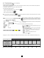
4.4 Transient mode
(on C.A 8334B only)
Press on the display mode key
Transient states can be displayed as curves. All the channels (6) are stored in memory for each transient state (irrespective
of the connection configuration).
It is possible to capture up to a maximum of 50 transient states.
The function keys enable the user to:
- capture search programming for a new transient with
- display a captured transient with
- delete a captured transient with
■ The screen below, accessed with the
key, shows the programming to capture a new transient (if a search is currently
in process, the user can stop it by pressing on
)
When scanning for transient states, a progression bar is
displayed, indicating the ratio between the number os transient
states already found and the programmed number of transient
states.
Number of transient states that can still be recorded (refreshed
in real time).
Transient search start and end time
Press on the
keys to select the parameters and on the
keys to modify them.
- Setting trigger thresholds : 1%, 2%, 5%, 10%, 20%, 50%,
100%, for voltage and current.
- Choice of the name and number of transients with the keys:
selection of the character place (a maximum of
7 characters)
selection of the alphanumeric value
Validate with the
key
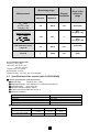
If tripping is on current, a recording of the voltage and current waveform is made on all the measurement channels (6 in all).
MN 200A clamp meter
MN 100A clamp meter
Clamp meter C
AmpFLEX
Clamp meter PAC
Clamp meter MN 5A
Adaptator 5A
Voltage
100%
200
100
1000
2900
1000
50%
100
50
500
1400
500
20%
40
20
200
580
200
THRESHOLD
10%
20
10
100
290
100
5%
10
5
50
140
50
2%
4
2
20
58
20
1%
2
1
10
29
10
9,6
4,8
[(Primary × 5) ÷ (Secondary)] × (Percentage ÷ 100)
480
240
96
19
48
24
■ The screen below can be accessed with the
key and displays a transient previously stored in the memory.
Displays the memory occupied by transients stored
Transient time and date recording
keys to select the transient and validate
Press on the
with the
The
(
key
keys are also used to select a transient to be deleted
); then validate with
.
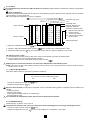
■ Storing trigger
The threshold T in percent, define an envelope width over and under the last cycle of signal V and A.
Let S(t) depend on a T-periodic signal and L be the half-width of the selected tube.
The sample having value S(to) is then considered to be “transient state recording triggering” if and only if
S(to) ∉] S(to-T) - L; S(to-T) + L [ and the apparatus is not already processing a transient state.
■ The screen below displays the transient selected on the previous screen:
-
Representation on the screen of 4 periods of 256 counts/periods
with 1 cycle before the trigger and 3 cycles after
Display of the date and time the transient was recorded
The curves to be displayed are selected by pressing on the
keys:
- 3V displays the three single voltages during the transient,
- 4A displays the three currents and the neutral current during
the transient,
- L1, L2 or L3 display the single current and voltage in turn
on phase 1, 2 or 3.
Instant values of signals at an instant “t”, in relation to the cursor
on the time scale with the
keys
NB : The “Trigger” sample is included within the time interval
[0 ; T/8[ (where T is the signal period).
■ After selecting 3V
This key allows the user to return to the transient selection screen
20
■ After selecting L1
These keys allow the user to change the time scale (screen
display of 4, 2 or 1 periods) centered on the cursor, which
v keys, giving, for example,
can be moved with the
the next screen by pressing on
.
All the transients stored can be exported to a PC equipped with the “QualiStarView” operating software.
4.5 Alarms Mode
- Press on the display mode key
- The next screen presents the various alarms stored.
Note: The threshold values must first have been programmed in the
mode
GO launches alarm capture
stop alarm capture
poub deletes all stored alarms
Alarm target
measurement parameter surveyed
maximum or minimum amplitude
Alarm duration
Alarm memory status
Selection of alarms with the
keys
Display of alarms within a period of time with
the
keys
Note: All the alarms recorded can be exported to a PC with the operating software. Up to 4096 alarms can be captured.
The alarm values recorded in W, VAR, PF, DPF and Tan? are in absolute values.
Note : The type of connection selected in the
mode has no influence on the possibilities of choosing the alarm
target and monitored parameter. The user is responsible for making pertinent choices.
21
4.6 Recording Mode
This mode enables all the parameters previously configured in the
mode to be recorded.
The function keys available in this mode enable:
- a new record to be made with
- an record to be displayed with
- an record to be deleted with
■ Saving selected parameters
This scale allows a current record to be displayed
Press on the
keys to select the parameters and on the
keys to modify them.
- Modification of the configuration number with the
(CONFIG 1, 2, 3 or 4)
- Modification of the dates with the
keys
- Entering of the record name with the
through the alphabet and numbers
Validate with the
keys
keys which scroll
key
The possible recording integration periods are:
1s, 5s or 20s and 1, 2, 5,10 or 15min
Stop recording
Note: the start and end dates are adjusted according to the chosen recording integration period.
"PERIOD" does not refer to a sampling period but to an integration period (average).
Note : The device calculates in real time the storage needs of the recording and if necessary displays the message “Not enough
memory».
■ Selecting or deleting a record
Press the
mode key:
The screen below can be accessed with the
key and displays a record previously stored in the memory.
Displays the memory occupied by previous records
To select:
Press on the
validate with the
keys to select the record required and
key
or to delete:
select the record to be deleted with the
on
keys and press
, validate with
Tip!: It is possible to display a measurement being recorded by selecting the name of the recording. To refresh the screen, press
the mode key
(caution: loss of cursor position and zoom).
The following screen opened using a key, is a way of consulting a recording previously stored in memory.
The device makes an automatic correction if the programming dates and times do not match:
- the current date
- the current time
- the set recording integration period (it is advisable to set times that are multiples of the integration period).
Note: the instrument automatically corrects the start and end time in order to improve the readability of the time scales of the
recording mode (graph representation).
22
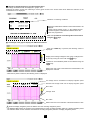
■ Selecting a graphic display for recorded measurements
Recordings of measurements are displayed in graphic form
Selecting the "TEST" record (see “selecting a record”) gives access to the screen below which allows the selection of the
measurement to be displayed:
Indication of recording conditions
These keys enable direct selection of the measurement to be
displayed.
A series of short presses on the “../..” key enables the user
to scroll through the measurements selected when this
record was programmed.
Note : It is possible to scroll through the measurements
using the
keys.
■ An example of the graphic display of V RMS measurements
- When the V RMS key is pressed, the following screen is
displayed:
Display of the average voltage for each of the 3 voltages, hourby-hour by moving the cursor with the
keys.
3 phases or each individual phase can be selected using the
keys
Returns the user to the screen where the measurement to be
displayed is selected
- When the L1 phase is selected, the following screen is displayed:
The average value is calculated for the display integration period
Extremes and average values over the display integration period
Max. value
Average value
Min. value
Returns the user to the “Selection of the measurement to view"
When the display integration period is different from the recording integration period:
- The displayed Avg value is the average of the measurements for each recording integration period in a display integration period
- The extreme values are the minimum and maximum recording integration periods in a display integration period.
23
■ Graphic display of average power
After returning to the “Selection of the measurement to view” screen with the ../.. key and pressing on the W key, the user obtains:
Average value of the active power on the L1 phase, by moving
the cursor with the
keys:
Note: Hold the selected key down to switch to fast forward
■ Energy measurement for a determined period
The energy over a selected period can be deduced from the
average power records:
End time
- Press on the
function key when the cursor is
positioned on the start instant of the energy calculation
- Move the cursor with the
keys to select the end instant
The energy value is displayed, with end dates and times.
In this way, it is possible to make an energy measurement over
several recording ranges in the 4 quadrants.
Note: All the data concerning a recording campaign can be exported to a PC using the software «QualiStarView».
Note: The
and
keys are used for changing the display integration period of the displayed measurement and
the time scale of the graphics.
Display integration period
Graph scale
2 hours
over 5 days
1 hour
over 2 1/2 days
15 minutes
over 15 hours
10 minutes
over 10 hours
5 minutes
over 5 hours
1 minute
over 1 hour
20 seconds
over 20 minutes
5 seconds
over 5 minutes
1 second
over 1 minute
Note: The minimum display integration period is limited by the recording integration period.
The recording integration period of 2 minutes is a special case. In this case, only the following display integration periods are
possible: 10 minutes, 1 hour and 2 hours.
24
4.7 Screen Memorisation
The
key allows 8 or 12 displays to be saved (according to the instrument model) for recall or display later on.
■ A long press (about 3 s) on this key freezes the current screen:
icon is displayed as soon as the operation has
The
finished.
This icon is replaced by
memory to record the photo.
if there is no space left in the
Note: These screens can be stored on a PC via the
QualiStartView operating software.
■ A short press (about 1 s) on this key gives access to the menu of screens already saved:
The selection of the screen to be displayed (or erased) is carried
out using the
and
keys
To display the screen selected, press on
validation
key.
To delete the screen selected, press on
validation
then on the
then on the
key.
To exit from the display of the recorded screen and return to the display of the recorded screen menu, press the
key
again.
Important note: the various storage spaces of C.A 8332B and C.A 8334B are of a fixed size and are completely independent of
one another (partitioned). There are 4 spaces for C.A 8334B (alarms, photographs, transient states and recordings) versus 3
for C.A 8332B (less the transient states).
25
4.8 Printing
The
key allows a screen to be printed immediately on a dedicated printer connected to output
In the example opposite, one press on the
➈
key freezes the
current screen, in this case, the
icon replaces
, a
bargraph indicates the progress of the data being transferred.
The original
finished.
icon reappears when the operation has
The current operation can be stopped – in the event of an
error, for example – by pressing on the
key again during
the data transfer process.
Note:
It will take a few seconds for the
icon to appear.
The fixed print transmission speed is 19.2 kbps.
The dedicated printer for the Qualistar is "DPU 414 - SEIKO" (see § 9.3)
4.9 Help
The
key allows the user to obtain help in the selected language for the current display mode.
Example:
display is in use, one press on the
While the
displays the information opposite.
key
4.10 QualistarView software
The QualistarView software is running on Windows 9x, NT4, Me, 2000 and XP.
Run Setup.exe
Setup of serial communication:
- On Qualistar (Setup mode)
- On the software "Qualistar View" (Submenus : Options > Communication)
Nota: the communication speed must be the same on the Qualistar and the "QualistarView" software.
Once the speed has been configured start retrieving the Qualistar configuration (Submenu: Options > Setup Qualistar) to see
how the serial communication works.
The data imports from Qualistar (to the PC) generate backups of files specific to Qualistar View of
which the extensions are as follows:
- “.mon” (for a recording)
- “.trs” (for a transient state)
- “.bmp” (for a screenshot)
- “.ala” (for a complete or customized alarms log)
- “.per” (for the recording of a measurement and a data channel to which a display integration period is assigned other than the
recording integration period of Qualistar)
- “.trt” (for a recording to which a voltage transformer ratio of 1 to 2999 has been applied)
26
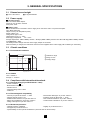
5. GENERAL SPECIFICATIONS
5.1 Dimensions and weight
■ 240 x 180 x 55mm
■ 2,1kg with batteries
5.2 Power supply
■ AC mains supply
With an internal mains adaptor
Range for use: 85-265V 50/60Hz
Max. power: 40VA
■ Battery power
Allows the instrument connected to the AC supply to be used in the event of a power interruption.
Type: NiMH 4000 mAh
Output: 4-wire (2 for temperature probe)
Rated voltage: 9.6V
Charge time: approx. 5hrs
Temperature for use : 0°...+50°C
Recharging temperature : +10°...+40°C
Storage temperature : -20°C...+50°C ( duration ≤ 30 days) -20°C...+40°C ( duration form 30 to 90 days) -20°C...+30°C ( duration
from 90 days to 1 year).
The battery starts to charge when the mains supply adaptor is connected.
When the battery is charged, the instrument uses the current supplied via the mains supply without drawing on the battery.
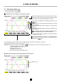
5.3 Climatic conditions
5.3.1 Environmental conditions
Relative humidity in % RH
95
90
➀ Reference range
➁ Range for use
➂ Storage range
75
➁
➂
➀
45
10
0
-20
0
20
26
35
50
Temperature in °C
5.3.2 Altitude
Use: 0..0.2000 m
Storage: 0...10 000 m
5.4 Compliance with international standards
5.4.1 Electrical safety (as per NF EN 61010-1 : 2001)
- Double insulation:
- Measurement category: IV
- Pollution level: 2
- Assigned voltage: 600 V RMS
- Inside use
5.4.2 Electromagnetic compatibility
- Immunity: as per NF EN 61236 - 1 : 2006
- Influence THD at 10V/M : 4.5%
- Radiation field resistance: as per IEC 1000-4-3
- Electric shock resistance: as per IEC 1000-4-5
- Voltage interruption as per IEC 1000-4-11
- Electrostatic discharges: as per IEC 1000-4-2
- Emission as per NF EN 61236 - 1 : 2006
- Fast transients resistance: as per IEC 1000-4-4
- Conducted RF interference: as per IEC 1000-4-6
5.4.3 Mechanical protection
- Operating position: Indifferent
- Rigidity: as per NF EN 61010-1
- If dropped: as per NF EN 61010-1
- Impermeability: IP 50 as per NF EN 60529 A1 (electrical IP2X for the terminals)
27
6. FUNCTIONAL CHARACTERISTICS
6.1 Reference conditions
Influence parameter
Ambient temperature
Humidity
Atmospheric pressure
Phase voltage
Current circuit input voltage other than AmpFlex
AmpFlex current circuit input voltage
Frequency of electricity network
V/I phase shift
Harmonics
Reference conditions
23°C ± 3K
45% RH
860 to 1060 hPa
230 V rms and 110 V rms ±2% without DC
0.03 V ≤ I ≤ In = 1 V rms without DC (< 0.5%)
11.8mV ≤ I ≤ In = 118 mV rms without DC (< 0.5%)
50 and 60 Hz ±0.1 Hz
0 degree or 90 degrees
< 0.1%
The uncertainties given for power and energy measurements are maximum for Cos ϕ = 1 or Sin ϕ = 1 and are typical for the other
phase shifts.
6.2 Electrical specifications
Sampling frequency: 12.8 kHz per channel at 50 Hz (256 samples per period)
6.2.1 Voltage inputs
■
■
■
Operating range: - phase – phase: 960 V RMS
- phase – neutral: 480 V RMS
Input impedance
: 340 kΩ between phase and neutral
Admissible overload : 1.2 Vn permanently
2 Vn for 1 sec
6.2.2 Current inputs
- Operating range:
0- 1 V
- Input impedance:
100 kΩ for the circuit other than AmpFlex and 12.4 kΩ for circuit AmpFLEX
- Admissible overload: 1.7 V
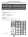
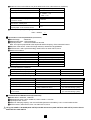
6.2.3 Characteristics of the device alone (without the current sensors)
Measuring Range
Measurement
Dislplay
Resolution
Error in the
reference
range
Minimum
Maximum
Frequency
40Hz
69Hz
0,01Hz
±(0,01Hz)
Single TRMS Voltages
6V
480V
0,1V
±(0,5%+0,2V)
TRMS Composite
Voltages
10V
960V
0,1V
±(0,5%+0,2V)
DC Voltages
6V
680V
0,1V
±(1%+0,5V)
1,2 × Inom
[A]
0,1A
I < 1000A
±(0,5%+0,2A)
Inom ÷ 1000
[A]
1A
I ≥ 1000A
±(0,5%+1A)
Other than
AmpFLEX
TRMS
Current
0,1A
I < 1000A
AmpFLEX
10A
6500A
±(0,5%+1A)
1A
I ≥ 1000A
(1) 1,2 × 1000 ×
2 = 1700 A
DC Currents
(clamp meter PAC)
28
0,1A
I < 1000A
1A
1700A(1)
±(1%+1A)
1A
I ≥ 1000A
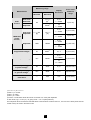
Measuring range
Display
Resolution
Measurement
Minimum
Peak
Current
Other than
AmpFLEX
Maximum
1,7 × Inom
[A](1)
0,1A
I < 1000A
9190A(2)
1A
I ≥ 1000A
0A
AmpFLEX
Other than
AmpFLEX
Inom ÷ 100
[A]
Error in the
reference
range
±(1%+1A)
1,2 × Inom
[A]
TRMS half
period
(5)
current
0,1A
I < 1000A
±(1%+0,5A)
1A
I ≥ 1000A
±(1%+1A)
0,1A
I < 1000A
AmpFLEX
100A
6500A
±(1,5%+4A)
1A
I ≥ 1000A
Single Peak voltages
6V
680V(3)
0,1 V
±(1%+0,5V)
0,1V
U < 1000V
Peak composite voltage
10V
1360V(4)
±(1%+0,5V)
1V
U ≥ 1000V
TRMS half period phase
(5)
to phase voltage
6V
480V
0,1V
±(0,8%+0,5V)
TRMS half period phase
(5)
to ground voltage
10V
960V
0,1V
±(0,8%+0,5V)
Peak factor
1
9,99
0,01
±(1%+0,02)
1) 1.2 x Inom x √2 = 1.7 x Inom
2) 6500 x √2 = 9190A
3) 480 x √2 = 680V
4) 960 x √2 = 1360V
5) Caution : The absolute offset value must not exceed 14% of the peak amplitude.
In other words, s(t) = S x sin (ωt) + O, giving us IOI ≤ 0.14 x S (with positive S).
The half period values are the MAX and MIN values of the waveform mode and the VRMS, URMS and ARMS values (other than the
neutral current) are used in the Alarm mode.
29
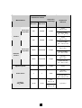
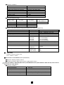
Etendue de mesure
Résolution
d'affichage
Measurement
Minimum
Other than
AmpFLEX
Erreur dans le
domaine de
référence
Maximum
±(1%)
Cos φ ≥ 0,8
0W
9999kW
4 digits
±(1,5%+10pts)
0,2 ≤ Cos φ < 0,8
Active
Powers
±(1%)
Cos φ ≥ 0,8
AmpFLEX
0W
9999kW
4 digits
±(1,5%+10pts)
0,5 ≤ Cos φ < 0,8
Other than
AmpFLEX
±(1%)
Sin φ ≥ 0,5
0VAR
9999kVAR
4 digits
±(1,5%+10pts)
0,2 ≤ Sin φ < 0,5
Reactive
Powers
±(1,5%)
Sin φ ≥ 0,5
AmpFLEX
0VAR
9999kVAR
4 digits
±(2,5%+20 pts)
0,2 ≤ Sin φ < 0,5
Apparent power
0
9999kVA
4 digits
±(1%)
±(1,5%)
Cos φ ≥ 0,5
Power factor
-1
1
0,001
±(1,5%+0,01)
0,2 ≤ Cos φ < 0,5
Tangent
VA ≥ 50VA
0,001
Tan φ < 10
-32,76
32,76
0,01
Tan φ ≥ 10
30
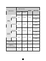
±(1°) sur φ
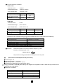
Measuring range
Display
Resolution
Measurement
Minimum
Error in the
reference range
Maximum
±(1%)
Cos φ ≥ 0,8
Other than
AmpFLEX
0Wh
9999MWh
4 digits
±(1,5%)
0,2 ≤ Cos φ < 0,8
Active
energy
±(1%)
Cos φ ≥ 0.8
AmpFLEX
0Wh
9999MWh
4 digits
±(1,5%)
0,5 ≤ Cos φ < 0,8
Other than
AmpFLEX
±(1%)
Sin φ ≥ 0,5
0VARh
9999MVARh
4 digits
±(1,5%)
0,2 ≤ Sin φ < 0,5
Energies
réactives
±(1,5%)
Sin φ ≥ 0,5
AmpFLEX
0VARh
9999MVARh
4 digits
±(2,5%)
0,2 ≤ Sin φ < 0,5
Apparent energy
0VAh
9999MVAh
4 digits
±(1%)
Unbalance
(three phase system)
0%
100%
0,1%
±(1%)
Phase angle
-179°
180°
1°
31
±(2°)
Measuring range
Measurement
Minimum
Harmonics ratios
(VRMS > 50V)
(IRMS > Inom ÷ 100)
rang ∈ [1 ; 50]
Display
Resolution
Error in the
reference
range
0,1%
±(1%+0,5%)
Maximum
0%
999 %
±(3°)
rang ∈ [1 ; 25]
Harmonics angles
(VRMS > 50V)
-179°
1°
-180°
±(10°)
rang ∈ [26 ; 50]
(IRMS > Inom ÷ 100)
Total harmonics ration
0%
999 %
0,1%
±(1%+0,5%)
1
99,99
0,01
±(5%)
rang £ 50
Factor K
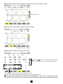
6.2.4 Nominal range of use
Frequency : 40 to 70Hz
Harmonics: THD (I) : 0 to 40%
THD (U) : 0 to 20%
Magnetic field: 0 to 400A/m
Electrical field: 0 to 3V/m
Relative humidity : 10 to 90%, free of condensation.
6.3 Specifications of the sensors (with C.A 8332B/34B)
■ Sensor characteristics C193 (Accessories)
■ Nominal range:
1000A AC for f ≤ 1kHz
■ Measurement range: 3A to 1200A AC (I > 1000A not permanent)
■ Input/Ouput ratio:
1mV AC/ A AC
■ Maximum clamping capacity: 52mm
■ NF EN 61010-2-032, 600V CAT IV, POL 2
■ Reference conditions
Ambiant temperature
Humidity
Frequency
Distortion factor
Magnetic field of external origin
■
23°C ±3 K
20% to 75% of RH
48...65Hz
< 1% without superimposed DC current
< 40A/m (earth's magnetic field)
Error in the reference conditions *
Primary current (in A AC)
Precision
(in % of the input signal)
Phase shift (in °)
3...10A
10...100A
100...1200A
≤ 0.8%
≤ 0.3%
≤ 0.2%
≤ 1°
≤ 0.5°
≤ 0.3°
* Make a logarithmic interpolation between each specified value
32
■
Variations in the nominal field of use (to be added to the error under reference conditions)
Ambiant temperature from -10°C to +50°C
Humidity from 10 to 90%
Frequency in relation to accuracy
Positions of the cable in the jaws
Adjacent conductor carrying
a 50Hz AC current
Distortion of crest factor ≤ 6
and current ≤ 3000A peak
Distortion DC current ≤ 15A
superimposed on the nominal current
■
≤ 200 ppm/K or 0.2% per 10K
< 0.1%
30...48Hz : < 0.5%
65...1000Hz : < 1%
1...5kHz : < 2%
< 0.1% for f ≤ 400Hz
≤ 0.5mA/A
< 1%
< 1%
Overloads : Frequency derating beyond 1kHz :
I max ≤ 1000A x
■
1
f (kHz)
Specifications of the AmpFLEX A193 (accessories)
■
■
■
■
■
■
Nominal range
: 3000A AC
Measurement range : 10A to 6500A AC
Input/Ouput ratio
: 140mV AC/3000A AC at 50Hz
Note : the ouput is proportional to the amplitude and the frequency of the measured current
Diameter of the sensor: 140mm Ø / length 450mm or 250mm Ø / length 800mm
NF EN 61010-1 and 2 (electrical safety) 1000V CAT III or 600V CAT IV, POL 2
Reference conditions
Ambient temperature
Humidity
Position of conductor in the sensor
Continuous magnetic field
External alternative magnetic field
External electric field
Frequency
Type of signal measured
■
Error in the reference conditions
Primary current (in A AC)
Precision (in % of the input signal)
Phase shift at 50 Hz (in °)
■
18°C à 28°C
20% to 75% of RH
centered
< 40A/m (earth's magnetic field)
none present
none present
from 10Hz to 100Hz
sinusoidal
10A...100A
≤ 3%
≤ 1°
100A...6500A
≤ 2%
≤ 0.5°
Variations in the nominal working range (to be added to the error under reference conditions)
Influencing factors
Influence range
Error
Temperature
-20°C to +60°C
0.2% per 10 K
Relative humidity
10% to 90% RH
0.5%
Frequency response
10Hz...20kHz
0.5%
Position of conductor in clamp
Any position on the internal perimeter
of the undeformed sensor
2%
(4% near the latching system)
Adjacent conductor carrying
an AC current
Conductor in contact with the sensor
1%
(2% near the latching system)
■ Characteristics of PAC93 sensors (accessories)
■ Rated calibre: 1000A AC, 1400A DC
■ Measurement range: 10A to 1000A AC, 10A to 1400A PEAK AC+DC
■ Input/output ratio: 1mV/A
■ Maximum clamping capacity: one 39 mm Ø cable (two 25 mm Ø cables), a 50 x 12 mm busbar section
■ NF EN 61010-2, 600V CAT III, POL 2 or 300V CAT IV, POL 2
Using C.A 8332B / C.A 8334B (600V CAT IV) with PAC 93 sensors (600V CAT III or 300V CAT IV) involve the set
600V CAT III or 300V CAT IV.
33
■
Reference conditions
Temperature
Relative humidity ratio
Battery voltage
Position of the conductor in the sensor
Magnetic field
AC external magnetic field
External electrical field:
Frequency range
Type of signal measured
■
Error in the reference range
Primary current
Accuracy
Primary current
Phase angle
■
18°C to 28°C
20% to 75% RH
9V ±0.1V
centered on the clamp marks
DC magnetic field
none
none
≤ 65Hz
sinusoidal
10...100A
100...800A
800...1000A AC
800...1400A PEAK
≤ 1.5% +1A
≤ 3%
≤ 5%
10...100A
100...1000A
≤ 2°
≤ 1.5°
Variation in the rated utilisation range (to be added to the reference range error)
Influence parameter
Influence range
Error
Temperature for use
18°C….28°C
ZERO: ≤ 0.2A/K
SCALE: ≤ 300ppm/K or 0.3%/10K
Battery voltage
6.5V to 10V
≤ 1A/V
10% and 90% RH
DC at 440Hz
DC at 1Hz
DC at 2Hz
DC at 5Hz
≤ 0.5% of the reading
< 0.5% of the reading
< 1% of the reading
< 3% of the reading
< 10% of the reading
Live adjacent conductor
50 and 60Hz
< 10mA/A AC (23 mm from the clamp)
External field
400A/m
< 1.3A
Rejection in common mode (in AC)
50 to 400Hz
> 65dB
Remanence in DC
+1400A DC at
-1400A DC
< 4mA/A
Frequency of the measurement signal
65Hz to 440Hz
440Hz to 1kHz
1kHz to 10kHz
-2%
-5%
-4dB
Position of a 20 mm Ø 20 conductor
■
OVERLOADS
Derating in frequency beyond 1kHz
Imax ≤ 1000A x 1 / f (kHz)
■ Specifications of the MN93A sensors (accessories)
Maximum clamping capacity: 20 mm
NF EN 61010-2-032, 600V CAT III, POL 2 or 300V CAT IV, POL 2
Using C.A 8332B / C.A 8334B (600V CAT IV) with MN 93A sensors (600V CAT III or 300V CAT IV) involve the set
600V CAT III or 300V CAT IV.
■ Reference conditions
■
■
Ambiant temperature
Humidity
Frequency
Distortion factor
Magnetic field of external origin
23°C ±3 K
20% to 75 % of RH
from 48...65 Hz
< 1% (without superimposed DC current)
< 40 A/m (earth's magnetic field)
Position of the cable
Centered
34
■
Error in the reference conditions
Calibre 100A
- Nominal current :
100A AC
- Measurement range :
100mA to 120A AC
- Input / Output ratio :
10mV AC / A AC
Primary current (A AC)
Accuracy
(as % of the input signal)
Phase shift
100mA...1A
1A...120A
≤ 0.7% + 2mA
≤ 0.7%
≤ 1.5°
≤ 0.7°
Calibre 5A
- Nominal current :
5A AC
- Measurement range :
5mA to 6A AC
- Input / Output ratio :
200mV AC / A AC
Primary current (A AC)
Accuracy
(as % of the input signal)
Phase shift
■
5mA...50mA 50mA...500mA
≤ 1% + 0.1mA
≤ 1%
≤ 1.7°
≤ 1°
■
≤ 0.7%
≤ 1°
Variation in the nominal working range (to be added to the error under reference conditions)
Influencing factor
Ambiant temperature
Humidity (10 ... 90%)
Frequency (40Hz ... 1kHz)
Frequency (1kHz ... 3kHz)
Position of conductor in clamp
Adjacent conductor carrying a 50Hz AC current
■
500mA...6A
Overloads :
Measurement influencing
≤ 200ppm/K or 0.2%/10K
< 0.2%
< 0.7%
< 2%
< 0.5% to 50/60Hz
< 15mA/A
Continuous maximum current from 100A to frequency ≤ 1kHz
Frequency derating beyond 1 kHz :
1
I max ≤ 100 A x
f (kHz)
Output maximal voltage (saturated secondary) from 8V max. peak.
Specifications of the adapter box 5A (accessories)
Nominal range : 5 A
Measurement range : 1 mA to 6 A
■ Input / Output ratio :
0,2 mV AC / mA AC
■ NF EN 61010-2, 300V CAT III or 150V CAT IV, POL 2
Using C.A 8332B / C.A 8334B (600V CAT IV) with adapter box 5A (300V CAT III or 150V CAT IV) involve the set
300V CAT III or 150V CAT IV.
■
■
■
Reference of conditions
Ambiant temperature
Humidity
Frequency
Magnetic field of external origin
Other channels
23°C ± 3K
50% to 85% of HR
48 to 500 Hz
< 40 A /m (earth’s magnetic field)
No connected
35
Error in the reference conditions
■
Primary current (A AC)
Accuracy (as % of the input signal)
1mA … 50mA
≤ 1%
50mA … 6A
≤ 0,5%
Phase shift
≤ 1°
≤ 0,2°
Variation in the nominal working range (to be added to the error under reference conditions)
■
Influencing factor
Ambient temperature
Frequency (30 Hz ... 48 Hz)
Frequency (48 Hz ... 500 Hz)
Frequency (500 Hz ... 1 kHz)
Frequency (1 kHz ... 5 kHz)
Measurement influencing
≤ 0,1% / 25K
< 0,2% + 0,2°
< 0,1% + 0,1°
< 0,3% + 0,2°
< 0,5% + 1°
Permanent Overload : 10 A
■
■ Specifications of the MN93 sensors (accessories)
Nominal range:
200A AC for f ≤ 1kHz
Measurement range: 2A to 240A AC (I > 200A not permanent)
■ Input/Ouput ratio:
5mV AC/ A AC
■ Maximum clamping capacity: 20mm
■ NF EN 61010-2-032, 600V CAT III or 300V CAT IV, POL 2
Using C.A 8332B / C.A 8334B (600V CAT IV) with MN 93 sensors (600V CAT III or 300V CAT IV) involve the set 600V
CAT III or 300V CAT IV.
■ Reference conditions
■
■
Ambiant temperature
Humidity
Frequency
Distortion factor
Magnetic field of external origin
■
Error in the reference conditions
Primary current (in A AC)
Accuracy
(as % of the input signal)
Phase shift (in °)
■
23°C ±3 K
20% to 75 % of RH
48...65 Hz
< 1% without superimposed DC current
< 40 A/m (earth's magnetic field)
2...10 A
10...100 A
100...240 A
≤ 3% +1A
≤ 2.5% +1A
≤ 1% +5 mV
≤ 6°
≤ 3°
≤ 2°
Variations in the nominal working range (to be added to the error under reference conditions)
Ambiant temperature from -10°C to +50°C
Humidity from 10 to 90%
Frequency in relation to accuracy
Positions of the cable in the jaws
Adjacent conductor carrying
a 50 Hz AC current
Distortion DC current < 20 A
superimposed on the nominal current
Distortion of crest factor ≤ 3
and peak current = 200 A
■
≤150 ppm/K or 0.15% per 10 K
<0.2%
40 Hz...1 kHz : < 3%
1...10 kHz
: < 12%
<0.5% to 50/60 Hz
≤ 15 mA/A
< 5%
≤ 3%
Overloads : Frequency derating beyond 1 kHz :
I max ≤ 1000 A x
1
f (kHz)
36
■
MAINTENANCE AND CALIBRATION OF CAPTORS
- Clean with a sponge moistened with soapy water and rinse in the same way with clean water, then dry it quickly.
- Keep the jaw gaps of the clamps (MN93A, MN93, C193 and PAC 93) perfectly clean using a cloth; slightly oil the visible metal
parts to avoid rust.
- Check the calibration every 2 years.
7. MAINTENANCE
For maintenance, use only specified spare parts. The manufacturer will not be held responsible for any accident occuring
following a repair done other than by its After Sales Service or approved repairers.
7.1 Recharging the battery
The instrument’s batteries are charged when it is connected to the AC mains supply.
For safety and trouble-free operation of the charger, the battery must be changed when de-energised with the equipment
turned off and there must be a delay of at least one minute without the battery being connected.
Do not dispose of the battery on a fire.
Do not expose the battery to heat exceeding 100°C.
Do not short circuit the battery terminals.
7.2 Cleaning the housing
Clean the unit with a cloth and a little soapy water. Clean off with a damp cloth.
Do not use solvents.
7.3 Metrological check
Like all measuring or testing devices, the instrument must be checked regularly.
This instrument should be checked at least once a year. For checks and calibrations, contact one of our accredited metrology
laboratories (information and contact details available on request), at our Chauvin Arnoux subsidiary or the branch in your
country.
7.4 Repairs
For all repairs before or after expiry of warranty, please return the device to your distributor.
37
8. TO ORDER
■ Power Quality Analyser : ............................. C A 8
3
3
2 B
C A 8
3
3
4
B
Instrument comes complete (as per grill) with:
- 1 QualiStarView software
- 1 DB9F standard optical lead
- 4 x 3m leads fitted with banana plugs
- 4 crocodile clips
- 1 mains lead
- and these operating instructions
■
Versions
French ................................................................................................................. F R
International ........................................................................................................ I N
■
Current sensors in a shoulder bag
None .......................................................................................................................................... X
Set of 3 x C 193 clamps (1000 A - Ø 52 mm) ............................................................................ C
Set of 3 x AmpFLEX A 193 (3000 A - Ø 140 mm / 450 mm long) ............................................. A
Set of 3 x AmpFLEX A 193 (3000 A - Ø 250 mm / 800 mm long) ............................................. A
Set of 3 x MN 93A clamps (100 A - 5 A - Ø 20 mm) .................................................................. M
Set of 3 x PAC 93 clamps (1400 A - Ø 42 mm) ......................................................................... P
■
X
X
1
2
N
A
Languages of operating instructions
French ...................................................................................................................................................... F
English (by default) ................................................................................................................................ G
German ................................................................................................................................................... A
Italian ....................................................................................................................................................... I
Spanish ................................................................................................................................................... E
Portuguese .............................................................................................................................................. P
■
R
B
L
T
S
T
Mains lead 2P
French, German or Spanish (by default) .............................................................................................................. F
English ................................................................................................................................................................. G
Italian ..................................................................................................................................................................... I
Swiss .................................................................................................................................................................... C
Or:
Power
Power
Power
Power
Power
Power
Power
Power
Quality Analyser C.A 8332-F with MN clamp ..................................................................................................
Quality Analyser C.A 8334-F with MN clamp ..................................................................................................
Quality Analyser C.A 8332-F with AmpFLEX ..................................................................................................
Quality Analyser C.A 8334-F with AmpFLEX ..................................................................................................
Quality Analyser C.A 8332-Int with MN clamp ................................................................................................
Quality Analyser C.A 8334-Int with MN clamp ................................................................................................
Quality Analyser C.A 8332-Int with AmpFLEX ................................................................................................
Quality Analyser C.A 8334-Int with AmpFLEX ................................................................................................
P01160501B
P01160601B
P01160502A
P01160602A
P01160503B
P01160603B
P01160504A
P01160604A
Accessories
Set of 3 x C 193-F clamps .......................................................................................................................................... P01120327B
Set of 3 x MN 93A-F clamps ....................................................................................................................................... P01120431B
Set of 3 AmpFLEX A193 - F Ø 450 mm ..................................................................................................................... P01120535B
Set of 3 AmpFLEX A193 - F Ø 800 mm ..................................................................................................................... P01120536B
Set of 3 x PAC 93-F clamps ........................................................................................................................................ P01120076B
Set of 3 x C 193-Int clamps ......................................................................................................................................... P01120321B
Set of 3 x MN 93A-Int clamps ..................................................................................................................................... P01120432B
Set of 3 AmpFLEX A 193 - Int Ø 450 mm .................................................................................................................. P01120523B
Set of 3 AmpFLEX A 193 - Int Ø 800 mm .................................................................................................................. P01120524B
Set of 3 x PAC 93-Int clamps ...................................................................................................................................... P01120077B
5A C.A 833x adaptor unit .............................................................................................................................................. P01101959
5A C.A 833x secura adaptor unit .................................................................................................................................. P01101990
Shoulder bag for N°6 cable ........................................................................................................................................... P01298051
Shoulder bag for instrument N°21 ................................................................................................................................ P01298055
■
38
Spare parts
4 Leads with banana plug RD + BL + GN + YE ............................................................................................................ P01295191
4 Leads with banana plugs RG + NR + BL + BC .......................................................................................................... P01295133
Crocodile clips RD + BL + GN + YE .............................................................................................................................. P01101962
Crocodile clips RG + NR + BL + BC + VJ ................................................................................................................... P01101849A
Carrying bag N°22 ........................................................................................................................................................ P01298056
C.A 833x strap ............................................................................................................................................................... P01298057
C 193 RD clamp ........................................................................................................................................................ P01120322B
C 193 BK clamp ......................................................................................................................................................... P01120323B
C 193 GN clamp ........................................................................................................................................................ P01120324B
C 193 YE clamp ......................................................................................................................................................... P01120325B
C 193 BL clamp ......................................................................................................................................................... P01120326B
■
MN 93A RD clamp ......................................................................................................................................................
MN 93A BK clamp ......................................................................................................................................................
MN 93A GN clamp ......................................................................................................................................................
MN 93A YE clamp ......................................................................................................................................................
MN 93A BL clamp ......................................................................................................................................................
P01120433B
P01120434B
P01120435B
P01120436B
P01120437B
MN 93 RD clamp ........................................................................................................................................................
MN 93 BK clamp .........................................................................................................................................................
MN 93 GN clamp ........................................................................................................................................................
MN 93 YE clamp ........................................................................................................................................................
MN 93 BL clamp ........................................................................................................................................................
P01120424B
P01120425B
P01120426B
P01120427B
P01120428B
PAC
PAC
PAC
PAC
PAC
P01120078B
P01120079B
P01120080B
P01120081B
P01120082B
93
93
93
93
93
RD clamp ......................................................................................................................................................
BK clamp ......................................................................................................................................................
GN clamp ......................................................................................................................................................
YE clamp .......................................................................................................................................................
BL clamp .......................................................................................................................................................
AmpFLEX A193
AmpFLEX A193
AmpFLEX A193
AmpFLEX A193
AmpFLEX A193
Ø 450 mm RD .................................................................................................................................
Ø 450 mm BK ..................................................................................................................................
Ø 450 mm GN .................................................................................................................................
Ø 450 mm YE ..................................................................................................................................
Ø 450 mm BL ..................................................................................................................................
P01120525B
P01120526B
P01120527B
P01120528B
P01120529B
AmpFLEX A193
AmpFLEX A193
AmpFLEX A193
AmpFLEX A193
AmpFLEX A193
Ø 800 mm RD .................................................................................................................................
Ø 800 mm BK ..................................................................................................................................
Ø 800 mm GN .................................................................................................................................
Ø 800 mm YE ..................................................................................................................................
Ø 800 mm BL ..................................................................................................................................
P01120530B
P01120531B
P01120532B
P01120533B
P01120534B
RS232 DB9F optical lead .............................................................................................................................................. P01295190
Ni-MH 4 Ah battery pack ............................................................................................................................................... P01296024
2P EUR mains lead ....................................................................................................................................................... P01295174
Printer DPU 414 - SEIKO ............................................................................................................................................ P01102903A
39
9. APPENDIX
9.1 Front view of the instrument
➉
11
12
➈
➀
➇
➁
➆
➅
➂
➄
➃
40
9.2 Mathematical formulae used to compute the various parameters
■ Half-period voltage and current RMS values
NechDemPer : number of samples in the "lobe" in question (between two consecutive zeros)
n : sample (0; 255) i : phase (0; 1; 2)
■ Min / max values for voltage and current
Vmax [i] = max (Vdem [i]), Vmin [i] = min (Vdem [i]),
Umax [i] = max (Udem [i]), Umin [i] = min (Udem [i]),
Amax [i] = max (Adem [i]), Amin [i] = min (Adem [i]), (Avg calculation over 1 s : cf "1s rms values...")
■ Peak values for voltage and current (updated on each waveform refresh)
Vpp [i] = max (V [i] [n]), Vpm [i] = min (V [i] [n]) n ∈ [0 ... NECHPER-1]
Upp [i] = max (U [i] [n]), Upm [i] = min (U [i] [n]) n ∈ [0 ... NECHPER-1]
App [i] = max (A [i] [n]), Apm [i] = min (A [i] [n]) n ∈ [0 ... NECHPER-1]
■ Peak factors for current and voltage.
■ 1 sec RMS values for voltage and current
41
■ Voltage and current unbalace
■ Calculation of the total harmonic distorsion factor (THD)
i : phase (0; 1; 2)
n : rang (2...50)
■ Calculation of harmonic bins (see p 11 FT/2)
By FFT (16 bits) 1024 samples on 4 cycles without windowing (CEI 1000-4-7). From real and imaginary parts, each bin ratio is
calculated on each phase Vharm[3][51], Uharm[3][51] and Aharm[3][51] in proportion to the fundamental value and the phase
angles Vph[3][51], Uph[3][51] et Aph[3][51] between each bin and the fundamental.
This calculation is done with the following principle:
module in % :
angle in degree:
Σ
Σ
ck
is the amplitude of frequency component
Fs sampled signal
co is the DC component
k
is the ordinal number (spectral bin)
42
Multiplying the voltage harmonic factor with the current harmonics factor gives the power harmonic factor. Differentiating
voltage harmonic phase angle with current harmonic phase angle gives power harmonic phase angle.
VAharm[3][51] , VAph[3][51
Nota : Available only for C.A 8334B
■
Distortion factor calculation (DF)
Two global values giving the relative quantity of harmonics are computed: the THD in proportion to the fundamental and the
DF in proportion to the RMS value.
■ K factor
■ Different power levels 1 sec
W [3] = W [0] + W [1] + W [2]
VA [3] = VA [0] + VA [1] + VA [2]
VAR [3] = VAR [0] + VAR [1] + VAR [2]
Total active power
Total apparent power
Total reactive power
■ Various ratios
43
■ Various types of energy
1st case : consumed energies (W[i] ≥ 0)
Total active energy consumed
Wh [0][3] = Wh [0] [0] + Wh [0][1] + Wh [0] [2]
Total apparent energy consumed
VAh [0][3] = VAh [0] [0] + VAh [0][1] + VAh [0] [2]
Total reactive capacitive energy consumed
VARhC [0][3] = VARhC [0] [0] + VARhC [0][1] + VARhC [0] [2]
Total reactive inductive energy consumed
VARhL [0][3] = VARhL [0] [0] + VARhL [0][1] + VARhL [0] [2]
44
2nd case : generated energies (W[i] ≥ 0)
Total active energy generated
Wh[1][3] = Wh[1][0] + Wh[1][1] + Wh[1][2]
Total apparent energy generated
VAh[1][3] = VAh[1][0] + VAh[1][1] + VAh[1][2]
Total reactive capacitive energy generated
VARhC[1][3] = VARhC[1][0] + VARhC[1][1] + VARhC[1][2]
Total reactive inductive energy generated
VARhL[1][3] = VARhL[1][0] + VARhL[1][1] + VARhL[1][2]
■ Hysteresis
Hysteresis is a filter principle often used after threshold detection stage. A correct setting of hysteresis value avoid repeated
state changing when the measure is varying close to the threshold.
The event detection is activate when the measure is going over the threshold but it can only be deactivated if the measure
goes under the threshold minus the value of the hysteresis.
The default hysteresis value is 2% of the reference voltage but it may be set in the range of [1%, 5%] depending of the voltage
stability on the network.
- Swell detection
Threshold of swell = Uref
Hysteresis = 2% Uref
Level to go back = 100% - 2% =
98% Uref
Swell duration
45
- Sag or interruption detection
Duration
Level to go back = (100% + 2%) Uref = 102% Uref
Hysteresis = 2% Uref
Threshold = Uref
Minimum scale values (in waveform mode) and minimum displayed
values.
Current sensor type
AmpFLEX 3000A
1000A PAC clamp
1000A C clamp
200A MN 93 clamp
100A MN 93A clamp
5A MN 93A clamp
5A Adaptor
Minimum displayed current value[A]
9
1
0,5
0,5
0,2
(Primary × 5) ÷ (Secondary × 1000)
(Primary × 5) ÷ (Secondary × 1000)
Minimum current scale value [A]
60
10
10
2
1
(Primary × 5 × 10) ÷ (Secondary × 1000)
(Primary × 5 × 10) ÷ (Secondary × 1000)
For all types of current sensors :
ARMS ≤ [Minimum value of displayed current] ⇒ ARMS = 0
For the MN93A clamp (rating 5A) and adaptor 5A :
■
■
Primary ∈ [1 ; 2999]
Secondary ∈{1 ; 5}
[Minimum displayed current value] ≤ 0,2 ⇒ [Minimum displayed current value] = 0,2
[Minimum current scale value] ≤ 1 ⇒ [Minimum current scale value] = 1
The minimum displayed voltage value is 5V
VRMS ≤ 5V ⇒ VRMS = 0
URMS ≤ 5V ⇒ URMS = 0
46
9.3 Setup DPU 414 printer
To setup the DPU414 printer, press ON and On Line at the same time.
47
03 - 2011
Code 689142E01 - Ed 5
DEUTSCHLAND - Chauvin Arnoux GmbH
Straßburger Str. 34 - 77694 Kehl / Rhein
Tel: (07851) 99 26-0 - Fax: (07851) 99 26-60
SCHWEIZ - Chauvin Arnoux AG
Moosacherstrass 15 - 8804 AU / ZH
Tel: +41 44 727 75 55 - Fax: +41 44 727 75 56
ESPAÑA - Chauvin Arnoux Ibérica SA
C/ Roger de Flor N° 293, Planta 1
08025 Barcelona
Tel: +34 902 20 22 26 - Fax: +34 934 59 14 43
UNITED KINGDOM - Chauvin Arnoux Ltd
Unit 1 Nelson Court - Flagship Square-Shaw Cross Business Park
DEWSBURY - West Yorkshire - WF12 7TH
Tel: +44 1924 460 494 - Fax: +44 1924 455 328
ITALIA - Amra SpA
Via Sant’Ambrogio, 23/25 - 20050 Bareggia di Macherio (MI)
Tel: 039 245 75 45 - Fax: 039 481 561
MIDDLE EAST - Chauvin Arnoux Middle East
P.O. BOX 60-154 - 1241 2020 JAL EL DIB (Beirut) - LEBANON
Tel: +961 1 890 425 - Fax: +961 1 890 424
ÖSTERREICH - Chauvin Arnoux Ges.m.b.H
Slamastrasse 29/2/4 - 1230 Wien
Tel: +43 1 61 61 961 - Fax: +43 1 61 61 961-61
CHINA - Shanghai Pu-Jiang - Enerdis Instruments Co. Ltd
3 F, 3 rd Building - N° 381 Xiang De Road - 200081 SHANGHAI
Tel: +86 21 65 21 51 96 - Fax: +86 21 65 21 61 07
SCANDINAVIA - CA Mätsystem AB
Box 4501 - SE 18304 TÄBY
Tel: +46 8 50 52 68 00 - Fax: +46 8 50 52 68 10
USA - Chauvin Arnoux Inc - d.b.a AEMC Instruments
200 Foxborough Blvd. - Foxborough - MA 02035
Tel: +1 (508) 698-2115 - Fax: +1 (508) 698-2118
www.chauvin-arnoux.com
190, rue Championnet - 75876 PARIS Cedex 18 - FRANCE
Tél.: +33 1 44 85 44 85 - Fax : +33 1 46 27 73 89 - [email protected]
Export : Tél. : +33 1 44 85 44 86 - Fax : +33 1 46 27 95 59 - [email protected]
48