1
General Purpose Input/Output (GPIO)
Configuration Manager
User’s Manual
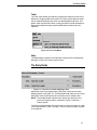
Product Warranty
Printronix warrants that the Products furnished under this Agreement shall be
free from defects in material and workmanship for a period of one year from
the date of shipment from the Printronix facility. This warranty is applicable
only if the products have had normal utilization within the published
specifications as modified from time to time, have been maintained in
accordance with recommended procedures with Printronix approved parts,
and have not been modified or altered in a manner not approved by
Printronix.
For printers sold within the area in which Purchaser normally provides field
service:
For all printers the Purchaser will provide the end-user with a 90-day
on-site warranty. Any printer or part therein found defective within one
year of original shipping date from a Printronix facility shall be returned to
Printronix and be repaired or replaced at the option and expense of
Printronix. Purchaser shall pay shipping cost to the Printronix facility and
Printronix will return the item(s) at its expense.
For printers sold outside the area, within the Continental United States, in
which Purchaser normally provides field service:
Any printer found defective within 90 days from the date of shipment to
the end user will be repaired at the end user’s location. If the end user is
located within 100 miles of an Authorized Service Provider’s location,
warranty service will be performed at no charge. If the end user is located
more than 100 miles from an Authorized Service Provider’s location,
travel time and expenses in excess of 100 miles will be billed to the end
user at current rates or the printer may be shipped to the nearest
Authorized Service Center for repair. If the end user elects to ship the
printer for warranty repair, the end user shall pay the shipping cost to the
Authorized Service Center and the printer will be returned at Printronix’
expense.
The Products may be equipped with a general purpose input/output circuit
board and corresponding pin connection (GPIO) which allow the Purchaser’s
or end user’s printer to function as a controller in a computer system.
Printronix publishes the specifications associated with GPIO and the pin
connection and warrants that the printer’s input and output parameters at the
pin connection conform to those specifications. Except as expressly
warranted, GPIO is sold on an “as is” basis. There are no other warranties
whatsoever, express or implied, concerning GPIO.
Purchaser’s remedies are expressly limited to Printronix’ obligations as stated
above, and in no event shall Printronix be held liable for any incidental or
consequential damages or loss of use, or other commercial loss, however
occasioned.
The warranties set forth in this article and the obligations and liabilities
thereunder are in lieu or, and the purchaser hereby waives, all implied
guarantees and warrantees, including without limitation, any warranty of
merchantibility or fitness for a particular purpose. In no event shall Printronix
be held liable for any incidental or consequential damages or loss of use, or
other commercial loss, however occasioned.
Notice of Copyright
This document contains proprietary information protected by copyright. No
part of this document may be reproduced, copied, translated, or incorporated
in any other material in any form or by any means, whether manual, graphic,
electronic, mechanical, or otherwise, without the written consent of Printronix,
Inc.
All non-Printronix registered and/or unregistered trademarks used throughout
this manual are the sole property of their respective owners.
COPYRIGHT 2003, 2013, PRINTRONIX, INC.
All rights reserved.
Table of Contents
1 Introduction ........................................................... 7
Overview................................................................................................ 7
Events and Actions ................................................................................ 8
The Hardware ........................................................................................ 8
2 The GPIO Manager............................................... 9
Overview................................................................................................ 9
The Menus .................................................................................... 10
The Entry Fields ............................................................................ 15
Events and Actions ....................................................................... 17
Entry Control Buttons........................................................................... 30
Multiple Actions ............................................................................. 31
The ON Flag.................................................................................. 32
The Status Line ............................................................................. 32
Data Fields........................................................................................... 33
Data Field Events And Actions...................................................... 34
Data Field Events .......................................................................... 37
Reports ................................................................................................ 39
Defining Reports ........................................................................... 40
Creating Sections .......................................................................... 41
Creating Reports ........................................................................... 43
Using Reports ............................................................................... 45
Timers.................................................................................................. 46
Delay Timer Mode ......................................................................... 46
Daily Timer Mode .......................................................................... 48
Weekly Timer Mode ...................................................................... 49
Using Timers ................................................................................. 50
Table of Contents
3 Mapping .............................................................. 53
Download Mapping Tables .................................................................. 53
Preloaded Table .................................................................................. 54
Mapping Examples .............................................................................. 55
Indicator Lights Example ............................................................... 55
Applicator Example ....................................................................... 56
Protected Printer Example ............................................................ 57
Panel Selected Label Printing ....................................................... 58
Pin Code Protected Printer .................................................................. 60
A Technical Information.......................................... 67
Opto-couplers ...................................................................................... 67
Relays.................................................................................................. 68
Voltages............................................................................................... 68
I/O Connector ...................................................................................... 68
B Basic GPIO Schematic Diagram ......................... 71
C Electrical Inputs And Outputs .............................. 73
GPIO Opto-coupled Input Circuit ......................................................... 73
GPIO Opto-coupled Output Circuit ...................................................... 73
D Contact Information............................................. 75
Printronix Customer Support Center.................................................... 75
Printronix Supplies Department ........................................................... 76
Corporate Offices................................................................................. 76
1
Introduction
Overview
This manual covers both the Basic and the Advanced General Purpose
Input/Output (GPIO) Manager.
The Basic GPIO Manager is available with the Advanced Tool Kit software
package.
The Advanced GPIO Manager is available as a stand alone software
package. It has all the functionality of the Basic GPIO Manager, with
additional features.
NOTE: This manual describes all functionality of the Advanced GPIO
Manager. Items that are not supported in the Basic GPIO Manager
are grayed out (not selectable) in the software.
This manual describes the Printronix GPIO function available for the
Printronix T5000 series Thermal printers.
NOTE: Only limited GPIO support is available for Line Matrix printers. Please
contact the Customer Support Center for information before ordering
Line Matrix printers with GPIO.
GPIO is both hardware and software. The hardware is the I/O board to be
mounted in the printer, and the software is the GPIO Manager. The GPIO
hardware is a printed circuit board containing optically isolated inputs and
outputs as well as relays. The GPIO software is both a printer resident GPIO
event parser and a PC-based GPIO manager that allows the user to define
how the general purpose I/O hardware should behave for the given
application.
The GPIO configuration manager is available as Basic GPIO Configuration
Manager (BGM) and Advanced GPIO Configuration Manager (AGM). This
user’s manual discusses both versions.
NOTE: AGM features in the printer can only be enabled by a special security
key.
7
Chapter
1
Events and Actions
Events and Actions
GPIO operation is based on Events and Actions. Events can be either printer
internal such as paper out or print complete, or they can be printer external
such as opto-coupler 1 active. Actions are the result of an event and can be
printer internal such as paper feed or printer external such as relay 1 active or
reply to host where data is transmitted over the serial, parallel, or network
interface. You can also define a number of events to be acted upon without
the GPIO card installed in the printer and allow the printer to be adapted for
the application in use.
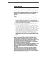
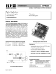
The Hardware
The GPIO hardware (Figure 1) consists of 16 opto-couplers, 4 SPDT relays,
and the logic required to connect this hardware into the printing system.
Eight of the 16 opto-couplers are used as isolated inputs; these are the
connections on which the external events happen. The remaining eight
opto-couplers and the four SPDT relays are used as isolated outputs. Each of
these outputs can be designated as an action in response to some event. The
board is connected into the printing system through the printer’s PCI bus.
None of the inputs or outputs is connected to any voltage source; it is the
user’s responsibility to make those connections. A separately fused 5 volt and
a separately fused 24 volt are available on the 50 pin connector in which all
inputs and outputs are terminated.
GPIO
Logic
Outputs 1 . . 8
Relay 1 . . 4
System Interface
Inputs 1 . . 8
Figure 1. GPIO Hardware
8
2
The GPIO Manager
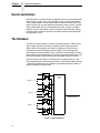
Overview
To launch the Advanced GPIO Configuration Manager, click the Start button
and navigate to ProgramsPrintronixGPIO Manager.
The screen in Figure 2 displays. The fields on this screen are described in
detail on the following pages.
Figure 2. The GPIO Configuration Manager
9
Chapter
2
Overview
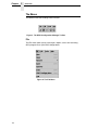
The Menus
The toolbars allow the handling of files and text.
Figure 3. The GPIO Configuration Manager Toolbar
File
The File menu allows you to create, open, reopen, save a new or existing
GPIO program file, or print GPIO configurations.
Figure 4. The File Menu
10
The Menus
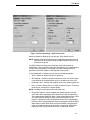
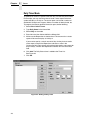
The Print option allows the mapping table to be printed for later reference.
When you select FilePrint, the GPIO Print Setup dialog box opens allowing
you to specify the desired print job. See Figure 5.
Figure 5. The GPIO Print Setup Dialog Box
11
Chapter
2
Overview
When you select FileGPIO Configuration the GPIO Configuration dialog
box opens. This allows you to define the GPIO properties and power-up
settings.
Figure 6. The GPIO Configuration Dialog Box
The Properties tab allows you to select the type of printer, either Thermal or
Impact, for which the mapping table will be designed. For security, the
password field allows you to password protect a mapping table.
NOTE: Password protected files can be uploaded to the GPIO manager but
cannot be edited or downloaded to a printer without the password.
12
The Menus
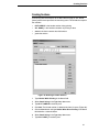
Figure 7. Power-Up Settings – GPIO Control Tab
Within the Power-Up Settings tab are two tabs, GPIO Control and IO.
NOTE: Settings made GPIO Control and IO predefining the output levels of
GPIO will only be functional when the Advanced GPIO features are
enabled in the printer.
The GPIO Control tab allows the specification of the GPIO power-on
configuration. This can be either the printer configuration or a predefined one.
If “Use Printer Configuration” is selected, initial GPIO settings will be as
specified in the Printer Power-On Configuration. See Figure 7.
If “Use Predefined” is selected, you can specify the following options:
•
•
GPIO – Enable or disable the GPIO at power-on.
•
•
Power-Up Table – specifies the mapping table to use following power-on.
GPIO Monitor – Switches the GPIO monitor on or off. The GPIO monitor
is the reflection of the opto-coupler inputs in the lower line of the LCD.
UCP – Universal Control Port is an offline available TCP port. To enable
the UCP port, checkmark the Enable option.
NOTE: Enabling the UCP port disables the PXML port.
•
Enable PAA Control – When enabled, PAA control matches from the
active CST table is reported to GPIO by the Data Field Changed event.
The predefined data field PAA State is used to generate the event. GPIO
can check this data field for changes. See “Data Field Events” on
page 37. PAA delays further data processing until GPIO acknowledges
the event. GPIO acknowledges the event by setting the PAA State field to
either NACK or ACK. When GPIO replies with NACK, PAA ignores the
match and sends the data to the emulation it is bound to. When GPIO
replies with ACK, PAA executes the match as defined in the CST.
13
Chapter
2
Overview
NOTE: GPIO does not always acknowledge the PAA trigger. If you use this
feature, make sure the event is always acknowledged.
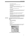
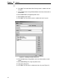
Figure 8. Power-Up Configuration – IO Tab
The Power-Up Settings – IO tab allows you to indicate what input conditions
can be expected and what output condition should be available at power-on.
By clicking the symbols the opto-coupler inputs or outputs can be activated
and the relays can be made to switch to the other position.
Edit
The Edit menu allows you to define, delete, and rename mapping tables. You
can also define data fields and reports to customize a mapping table. New
mapping tables can be added to the tables that will be downloaded to the
printer and existing mapping tables can be deleted or renamed.
NOTE: Definitions for New Mapping Table, Delete Mapping Table, Define
Data Fields, Define Reports, and Define Timers will only be functional
when the Advanced GPIO features are enabled in the printer.
Figure 9. The Edit Menu
14
The Entry Fields
Tools
The Tools menu allows you upload a mapping table from the printer and to
download a mapping table to the printer. You also have the option to select
the last selected upload printer or the last selected download printer. This
option allows you to quickly select a printer previously used for uploading or
downloading without having to go to the RMS printer database for your
selection.
Figure 10. The Tools Menu
Help
The About option provides basic information about the GPIO Configuration
Manager as seen in the startup splash screen.
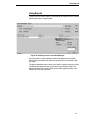
The Entry Fields
Figure 11. The Event To Action Mapping Fields
Setting the criteria for mapping tables takes place in the Event to Action
Mapping section (see Figure 11). The Description field allows you can enter a
descriptive name to indicate the use of the event and its related action.
NOTE: The window header indicates which printer type (thermal or line
matrix) the mapping table is created for. Figure 11 indicates a
Thermal printer.
The Event and Action fields allow you to select an event and apply an action
to the selected event. Table 1 on page 17 lists the events currently available
in the software.
15
Chapter
2
Overview
The Parameters button allows you to select additional conditions related to
the event (Figure 12).
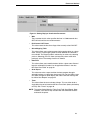
Figure 12. Setting Event Parameters
The action field allows you to select the action that is to be taken on the
specified event. Table 2 on page 24 lists the actions currently available in the
software.
The parameter button allows you to select additional conditions related to the
action. Figure 13 displays parameters for the Output Opto-coupler and Output
Relay actions.
Figure 13. Setting Action Parameters
16
Events and Actions
Events and Actions
The Events
Table 1 lists the available events and the related parameters. Events
parameters are available for the Input Opto-Couplers, Panel Key Pressed
events, Printer Error and Warning events (including RFID and ODV related
errors), and PAA events (related to Data fields and Timers).
Table 1: Events And Parameters
Events
Printer Type
Parameters
Input Opto-Coupler
Thermal, Line Matrix
Opto-Coupler Number (1..8), Active, Inactive
Printer Powered Up
Thermal, Line Matrix
n.a
Printer Online
Thermal, Line Matrix
n.a
Printer Offline
Thermal, Line Matrix
n.a
Printer Paused
Thermal
n.a
Power Save Mode Active
Thermal, Line Matrix
n.a
Power Save Mode
Cleared
Thermal, Line Matrix
n.a
Start Data Processing
Thermal, Line Matrix
n.a
End Data Processing
Thermal, Line Matrix
n.a
Printer Buffers Empty
Thermal, Line Matrix
n.a
Single Form Printing
Thermal, Line Matrix
n.a
Thermal, Line Matrix
n.a
Label Pending
Thermal
n.a
Start Printing
Thermal, Line Matrix
n.a
End Printing
Thermal, Line Matrix
n.a.
Start Paper Move
Thermal,
Line Matrix (only when
Single Page Printing is
active)
n.a
Label Printed
Thermal, Line Matrix
n.a
Label Present
Thermal
n.a
Label Taken
Thermal
n.a
Job Printed
Thermal
n.a
End Paper Move
Line Matrix
n.a
Invoked 1
Cont. Form Printing
Invoked
1
17
Chapter
2
Overview
Table 1: Events And Parameters
Printer Error
Thermal, Line Matrix
Thermal, Line Matrix
Thermal, Line Matrix
Thermal
Thermal
Thermal
Thermal
Thermal
Line Matrix
Line Matrix
Line Matrix
Line Matrix
Any
Paper Out
Paper Jam
Ribbon Out
TOF Detect Fault
Head Open
RFID Tag Failed
RFID Max Retry
Ribbon Stall
Platen Open
Stacker Fault
Stacker Full
Printer Warning
Thermal
Thermal
Any
Ribbon Low
Panel Key
Thermal, Line Matrix
Key Identifier
ODV Status
Thermal
Unscanable Code, Quality error – Any or a
specific one (list), all ODV errors cleared.
PAA Event
Thermal, Line Matrix
Event identifier
Data Field Changed 1
Thermal, Line Matrix
Data Field, Condition, Type, Value
Timer Expired 1
Thermal, Line Matrix
Timer Identifier
Table Entered 1
Thermal, Line Matrix
n.a
Table Exited 1
Thermal, Line Matrix
n.a
UCP Data In 1
Thermal
Value
1
Only functional with the Advanced Features enabled in the printer.
Event Descriptions
•
Input Opto-Couplers
For external input signals you can specify the number of the
opto-coupler to view and the level in which the event is seen as active.
Click the opto-coupler symbol
to select the active state.
18
Events and Actions
Figure 14. Setting the Opto-coupler Number and State
NOTE: With the Advanced Features enabled in the printer, it is possible to
handle all eight opto-coupler input as a special Data Field (see “Data
Fields” on page 33). This results in 248 different input combinations
that can be used to trigger an action.
•
Printer Powered Up
This event is delayed until the moment the printer reaches the Poweredup-online or Powered-up-offline state. The delay is required so the printer
can finish its power-on reset cycle before any reaction to an event
generates.
NOTE: With the advanced features enabled in the printer, GPIO will either
start up using the printer configuration or a predefined configuration.
Select FileGPIO Configuration then select the Power-Up Settings,
GPIO Control tab to set the power-up option.
•
Printer Online
When the printer goes online by pressing the Pause key, the action
related to this event is accepted.
•
Printer Offline
When the printer goes offline by pressing the Pause key or the menu key,
or if there is any other reason that causes the printer to switch offline, the
action related to this event is accepted.
•
Printer Paused
This event happens when the printer pauses because of the “pause
printer” action. The printer will accept data from the host and parse this
data until its buffers are full. No printing will take place. The print engine is
offline but the printer’s data processing unit is still online.
•
Power Save Mode Active
This event signals the moment when the printer enters Power Save
Mode.
•
Power-Save Mode Cleared
This event signals when the printer becomes active again.
•
Start Data Processing
This event signals the start of the processing of received data. This is not
the same as the Start Printing event.
•
End Data Processing
This event signals the end of the data processing cycle. This is not the
same as the end printing event.
•
Printer Buffers Empty
This event takes place as soon as the print buffers are emptied.
•
Single Form Printing Invoked
This event happens on the Enter Single Label Mode action. It indicates
that this mode has been entered.
19
Chapter
2
Overview
•
Continuous Form Printing Invoked
This event indicates that the Single Form Mode is terminated and that
normal, continuous printing is active.
•
Label Pending
This event generates when the printer is in Local mode (i.e., the print
engine is temporarily stopped) and all incoming data has been processed.
•
Start Printing
This event happens when the printer starts printing. The printer starts
printing when all data processing is done, there is actual data to print, and
the printer is no longer in local mode. The event will not happen on “paper
moves without print.”
•
End Printing
This event indicates the end of actual printing. The paper may still be
moving as printing does not always stop at top of form.
•
Start Paper Move
This event indicates the beginning of the paper motion.
•
Label Printed
This event occurs when a number of labels stored in the printer have
finished printing. If the labels print as a single job without any wait time,
the event will be a short pulse. If the printer is placed in local mode and
the labels are printed using the print next label action, the event will
happen once for each label.
•
Label Present
In label peel off applications, this event happens when the label present
sensor detects a label in position (ready for application). It may be used to
signal the availability of a label to an applicator system.
•
Label Taken
This event generates when the label is taken from its ready to apply
position. It can be used to tell the host that a new label can be printed.
•
Job Printed
This event generates if all print jobs in the buffer have printed.
•
End Paper Move
It indicates the end of the paper motion.
•
Printer Error/Printer Warning
Events that signal printer errors and warnings. They allow selection of the
actual error or warning that is to be seen as the event.
20
Events and Actions
Figure 15. Setting Event Parameters
To select the Printer Error event, click the Event drop-down menu and
select Printer Error as the event parameter. The Set Event Parameters
dialog box opens. Click the Any box to uncheck the setting. A list of errors
(or warnings) is now available for selection. From the Error drop-down
menu, select the required parameter.
The Set state identifies the event when the problem happens. The
Cleared state specifies the event when the problem is solved.
TOF Detect Fault happens if the T5000 does not find a Top of Form
indicator (or a gap) within a specified amount of time after printing starts.
It can be used to prevent the feeding of blank labels in print and apply
applications.
•
Panel Key
This is an event in which the operator panel keys are parameters. The
event allows you to change the function of the keys or to disable selective
keys. For example, if the panel key event Menu results in the action
Consume (or do nothing) the menu key has been disabled.
NOTE: When the Advanced Features are enabled in the printer, this allows
an event to be generated when multiple keys are pressed
simultaneously. Many additional key combinations can be used to
trigger an action.
21
Chapter
2
Overview
Figure 16. Setting Panel Key Event Parameters
•
ODV Status
This selection allows you to react to output from the Online Data
Validator. The parameters allow you to program GPIO to act if there is no
barcode, if there is any or a specific error in the barcode, or when all ODV
errors have been cleared.
Figure 17. Setting ODV Parameters
•
PAA
PAA generates an event on a user specified input string. A large number
(32000 or more) of PAA events can be generated through the use of an
identifier.
22
Events and Actions
•
Data Field Changed
This event happens if the value in a given data field changes. Certain
conditions are applicable, see “Data Fields” on page 33.
•
Timer Expired
This event happens when a user defined timer expires or when a user
defined time is reached. See “Timers” on page 46.
•
Table Entered
This event happens when a new mapping table is entered. The event can
be used to execute actions regarding new tables. For example, when you
want to check the content of a datafield and no other events are available.
•
Table Exited
This event generates before going to a new table. This event can also be
used to execute last minute actions. For instance, if we want to go from
table 1 to either table 2 or 3 and if a variable needs to be initialized, we
could use the table exited event. This way we only have to specify the
initial value once.
•
UCP Data In
This event generates when the data received on the Universal Control
Port (UCP) matches the data defined with the parameters of this event.
This event requires that the UCP port be enabled; a warning dialog will be
shown if this option is not enabled. This message displays only once for
each GPF editing sesion.
NOTE: The events Datafield Changed, Timer Expired, Table Entered, and
Table Exited, and UPC Data In are only functional with the Advanced
Features enabled in the printer.
23
Chapter
2
Overview
Actions
The Action field allows you to specify which action should be linked (or
mapped) to the selected event. Table 2 lists all possible actions and related
parameters.
Table 2. Event Actions and Parameters
Actions
Printer Type
Parameters
Output Opto-Coupler
Thermal, Line Matrix
Opto-Coupler Number (1..8), Activate,
Deactivate, Pulse Once, Pulse Repeat
Output Relay
Thermal, Line Matrix
Relay Number (1..4), Activate,
Deactivate, Pulse Once, Pulse Repeat
Printer Online
Thermal, Line Matrix
n.a
Printer Offline
Thermal, Line Matrix
n.a
On/Offline Switch
Thermal, Line Matrix
n.a
Clear Buffer
Thermal, Line Matrix
n.a
Pause Printing
Thermal
n.a
Start Printing
Thermal
n.a
Print Next Label
Thermal, Line Matrix
n.a
Reprint Last Label
Thermal
n.a
Form Feed
Thermal, Line Matrix
n.a
Move Paper
Thermal, Line Matrix
TOF, Specified Distance Forward/
Backward
Cut Once
Thermal
n.a
NOTE: When an Online Data Validator is
installed, the Cut Once action is
not executed.
Flush Next Label 1
Thermal
n.a.
Enter Single Form Printing 1
Thermal, Line Matrix
n.a.
Enter Cont. Form Printing 1
Thermal, Line Matrix
n.a.
RFID: Program Next Label 1
Thermal
n.a.
Lock Panel
Thermal, Line Matrix
n.a.
Unlock Panel
Thermal, Line Matrix
n.a.
Key Handling
Thermal, Line Matrix
Consume
Beep 1
Thermal, Line Matrix
Beep Count
24
Events and Actions
Table 2. Event Actions and Parameters
Actions
Printer Type
Parameters
Blink 1
Thermal, Line Matrix
On, Off, Blink
Disable GPIO Events
Thermal, Line Matrix
n.a.
Enable GPIO Events
Thermal, Line Matrix
n.a.
Reply to Host
Thermal, Line Matrix
Data to be Transmitted, Interface to use
Wait
Thermal, Line Matrix
Time to Wait in mSeconds
PAA Control: Reset CST
Thermal, Line Matrix
n.a.
Select Mapping Table 1
Thermal, Line Matrix
Name of Table to switch to, Previous
Table
Data Field 1
Thermal, Line Matrix
Destination, Operator, Evaluate, Source,
Type
Send Report 1
Thermal, Line Matrix
Name, Destination, Duration
Timers/RTC 1
Thermal, Line Matrix
Name, Duration, Repeat
1
Only functional with the Advanced features enabled in the printer.
25
Chapter
2
Overview
Action Descriptions
•
Output Opto-Couplers
The opto-coupler number to activate can be specified as well as the level
(or state) required for this output. Select the state by clicking the optocoupler symbol. If the Pulse parameter is selected, the pulse duration can
be set in increments of 50 msec between 50 and 2,147,483,647 msec.
This allows pulses up to 24.8 days in duration. If Repeated Pulse is
selected, the pulse will repeat with a 50% duty cycle until deactivated.
Figure 18. Setting Ouput Opto-coupler Action Parameters
•
Output Relay
The relay number to activate can be specified as well as the level (or
state) required for this output. You can select the state by clicking the
relay symbol. Pulsed behavior for the relays is equivalent to the pulsed
behavior of the opto-coupled outputs.
NOTE: The Advanced Features enabled in the printer allow handling all eight
opto-coupler outputs as well as the relays through a Data Field.
See “Data Fields” on page 33. This gives the single outputs a large
number of output combinations that can be used to initialize external
actions.
Figure 19. Output Relay Settings
26
Events and Actions
•
Printer Offline/Printer Online
These two actions switch the printer offline or online.
•
On/Offline Switch
This action allows the printer to be switched offline if it is online, and to be
switched online if it is offline. The switch works as a toggle.
•
Clear Buffer
A host or application controlled memory clear.
•
Pause Printing
This action results in the print engine going offline with the interface to the
host still active. This allows receiving and pre-processing of host data
until the buffer is full.
•
Start Printing
If there is data in the buffer, the printer starts printing until either it is
switched offline or paused through the Pause Printing action.
•
Print Next Label
This action can have different functions. If GPIO Print & Apply is enabled,
the action is Print Next RFID Label. In Single Label Printing Mode, the
action is Print Next Label. If the user switches the printer to Pause mode
without going into Single Label Printing Mode, the Print Next Label also
functions similar to the previous version of GPIO.
IMPORTANT
Do not place the printer in Pause mode and select the Single Label
Printing Mode, this stops the engine and prevents the printer from
printing.
•
Reprint Last Printed Label
Reprints the last page printed.
•
Form Feed
Performs a form feed.
•
Move Paper
This action allows the movement of paper either to the next top-of-form
(the gap) or, if required for specific applicator functions, a specified
distance forward or backward. See Figure 20.
Figure 20. Setting Move Paper Action Parameters
27
Chapter
2
Overview
•
Cut Once
Cuts the media in the current position.
•
Flush Next Label
This action removes a single form (the one that is ready to be printed)
from the queue in the printer. It can be used in Secure Printing
configurations where two printers are interconnected through GPIO and
one printer is ready to take over printing if the first printer develops a
problem.
•
Enter Single Label Printing
This action prints one label at a time.
•
Enter Continuous Label Printing
This action continuously prints the jobs in the entire buffer.
•
RFID: Program Next Label
This action is specifically designed for RFID Print and Apply applications
where the programming of the RFID tag in the label does not have to
occur simultaneously with the printing of the actual text on the label.
•
Lock Operator Panel / Unlock Operator Panel
Once executed, the front panel will be locked or unlocked. When locked,
the panel can still be accessed through the virtual front panel of the
Printronix Remote Management Software Advanced Tool Kit. If the
Disable Event Parser has been executed, the front panel will be unlocked.
•
Key Handling
This action allows the user to specify how the actual Key Event should be
handled. Selecting Consume results in the original key function not being
executed (it is consumed by GPIO).
•
Beep and Blink
These actions allow the beeper to beep a specified number of Times New
Roman. The Online lamp on the printer switches on, off or blinks at the
normal printer controlled rate.
•
Enable GPIO Events/Disable GPIO Events
These actions allow you to switch on or off the event parsing of GPIO.
When disabled, the only action GPIO will execute is the enable event
parser action.
•
Reply to Host
The Reply to Host action allows the user to specify a data stream that will
transmit to the host when the selected event takes place and to select the
interface that should be used for this data transmission. Data entry can be
in ASCII or in hexadecimal. The entry mode can be selected with the
arrow keys: up arrow for ASCII entry mode and down arrow for Hex entry
mode. See Figure 21.
28
Events and Actions
Figure 21. Setting Reply to Host Action Parameters
•
Wait
The parameter for this action specifies the time in 1/1000 seconds that
GPIO will wait until the next action executes.
•
PAA Control: CST Reset
This action resets the Use Once flags of the currently active PAA CST.
•
Select Mapping Table
This action allows you to select one out of 64 mapping tables on a given
event. If only a single mapping table has been defined, this selection is
not available. The mapping table is selected by its name or by selecting
previous. Selecting previous allows you to quickly return to the table
previously active. The nesting of returns is allowed.
•
Data Field
This action allows you to modify the data field on a given event. Several
logical or arithmetical functions can be applied to the data in the data
field. See “Data Fields” on page 33.
•
Send Report
This action transmits a report to either the host computer through a
selected interface or to the printer front panel LCD. For the LCD the user
can select the upper or lower display line and the time the message will
be visible. See “Reports” on page 39.
•
Timer
This action allows the start and stop of timers. This can either be for a
single delay time or be based on the Real Time Clock (battery backed-up
or CPU). See “Timers” on page 46.
NOTE: The actions Select Mapping Table, Data Field, Send Report, Beep
and Blink, and Timer is only available with the Advanced Features
enabled in the printer.
29
Chapter
2
Entry Control Buttons
Entry Control Buttons
The mapping table control buttons are used as follows:
•
New. Clears the Name field and sets the Event, Action, and related
parameters to default.
•
•
Add. Adds a new Event-to-Action mapping to the current GPIO program.
Update. Re-enters an Event-to-Action mapping after editing.
Click the buttons to copy an entry from the mapping table to the entry/edit
fields for subsequent modification. Click the Update button to update the entry
in the mapping table with the new data.
Figure 22. Event to Action Mapping Entry Control Buttons
The Uninterrupted checkbox is used to allow GPIO to finish an action without
being interrupted. For instance, if an event results in a timer action the timer
may be required to expire completely before another action is performed.
Events happening during this uninterrupted time will be queued and reacted
upon once the uninterruptable action is complete.
NOTE: The queued events will be acted upon directly and in sequence. Any
timing will be lost.
30
Multiple Actions
Multiple Actions
If required, GPIO can execute a number of actions on a single event. Multiple
actions specified for a single event will be executed in the order they are
entered in the mapping table.
Figure 23 shows a mapping table where the first action is to enable GPIO
events by making the Input Opto-coupler event active. The second action is to
disable GPIO events by making the Input Opto-coupler event inactive. The
third action is to perform a form feed. Since the GPIO Configuration Manager
performs mappings in sequence, this program will not produce a clean sheet
because the Form Feed action follows the GPIO disable command. A form
feed cannot happen when all GPIO events are disabled first.
Figure 23. Incorrect Setup of Multiple Actions
Figure 24 shows a correct mapping table; a form feed is executed before the
actual disabling of GPIO.
Figure 24. Correct Setup of Multiple Actions
To change the sequence in which the entries appear in the table, click and
drag the entry to a different location in the table.
31
Chapter
2
Entry Control Buttons
The ON Flag
You can use the On flag to temporarily disable entries in the GPIO mapping
table. This is useful if an extensive mapping table is generated with many
events leading to the same action. The On flag allows you to test each event
reaction separately.
Figure 25. Using the On Flag to Enable or Disable an Action
The Status Line
The status line displays information related to GPIO. The tabs marked
Table-1 and Table-2 allow selection of different event to action mappings.
With the Advanced Features enabled, it is possible to select up to 64 tables.
With the Advanced Features disabled, only a single table is available.
Figure 26. Viewing Status Line Information
The status line displays the date and time as well as the type of GPIO
features used in the table. The ‘A’ indicates that at least one advanced feature
is present. To run the mapping table in the printer the Advanced Features
need to be enabled by the security key. Tables using only basic features do
not require the security key to be loaded to the printer.
The series of zeros (or ones) are a reflection of the initial input and output
states defined during the GPIO configuration. The first set of eight zeros
represent the initial input opto-coupler state, the second set of eight zeros
represent the initial output opto-coupler state, and the last set of four zeros
represent the relays.
The Sub checkbox needs to be checked if a GPIO mapping table is to be
used as a subroutine. A table marked Sub will put the name of the table from
which the selection is done on the stack. This name is used when the “select
previous table” action is done to select the correct table to return to.
32
The Status Line
Data Fields
Figure 27. The Define Data Fields Dialog Box
Data fields are storage locations in the printer’s resident memory. To define a
data field, select EditDefine Data Fields. The Define Data Fields dialog
box opens (Figure 27).
The Name field allows the user to create a data field descriptive to the user’s
needs. The Type drop down menu allows you to choose one of seven
different types of data including 8, 16, or 32 bit signed or unsigned values and
a string value. The Initial Value field allows you to set an initial value for the
data type specified.
Checking the Non Volatile check box specifies that if a value in the data field
has changed during the operation of the printer and the printer is powered
down, the lastest value of the data field will be the initial value when the
printer is powered on. For example, if the data field contains a label count of
10,000 and that after printing 1,200 forms the printer is turned off due to error,
with Non Volatile selected, the printer prints another 8,800 forms when the
printer goes online again. If Non Volatile is not selected, the printer will print
another 10,000 forms.
33
Chapter
2
Data Fields
Data Field Events And Actions
Data Field Actions are used to modify the content of the Data Field which
results in an event.
An example is provided to better understand how Data Field Actions work in
correlation to Data Field Events. For this example, we have a printer with a
forms count defined in a data field in which after each form prints, the count is
updated to reflect the correct number of forms still to be printed. Once the
count reaches zero, we want a message to display in the second line of the
front panel. To do this, we need to define a Data Field and enter the total
forms count (Figure 28).
Data Field Actions
Figure 28. Defining Data Fields
1. Select EditDefine Data Fields.
2. Enter a descriptive name in the Name field.
3. Select the Data Field Type and enter the Initial Value.
The data field type can be signed or unsigned bytes (-128..+127 and
0..255), signed and unsigned words (-32768..+32767), signed and
unsigned long words (-2147483648..+ 2147483647), and ASCII strings.
4. Click Add to add the data field to the item list.
34
Data Field Events And Actions
Once the data field is defined and added to the list, make sure that the count
decrements by one each time a form prints. To set the parameters, use the
Label Printed event and the Data Field action. In the Data Field parameter
block specify what you want to happen when the event Label Printed occurs.
Figure 29. Setting Action Parameters
There may be an instance where you want to indicate an exact operation to
perform on the Data Field. To decrement the label count by one each time a
form prints, specify this event to happen in the Data Field parameter block
when a label printing occurs. The value in the Source field will be used during
the operation on the Data Field. To decrement the forms count by one for
each label printed, set the Source value to 1. If more Data Fields are defined,
one of those could be used as the Source value. To select the Source type,
click the Type drop down menu and select Fixed or another defined data field.
Operator Data Field Settings are defined in Table 3.
Table 3. Operator Data Field Setting
Operator
Results
D=S
Destination becomes Source
D=D+S
Destination ‘plus’ Source
D=D-S
Destination ‘minus’ Source
D=D*S
Destination ‘Times New Roman’ Source
D=D/S
Destination ‘divided by’ Source
D=D%S
Destination ‘mod’ Source
35
Chapter
2
Data Fields
Table 3. Operator Data Field Setting
Operator
Results
D=D|S
Destination ‘Logical OR’ with Source
D=D&S
Destination ‘Logical AND’ with Source
D=D^S
Destination ‘Logical EXOR’ with Source
D = D &~ S
Destination ‘Logical AND’ with ‘Inverted’ Source
D=~S
Destination becomes ‘Inverted’ Source
D = D >> S
Destination ‘Logical Shift Right’ Source Times
New Roman
D = D << S
Destination ‘Logical Shift Left’ Source Times
New Roman
First specify the data field itself, in this case a single (U16 Forms Count). If
there are numerous data fields, select the one in which the action should
apply. Next we need to set the operators to indicate the event we want to
happen to this data field. The Source field sets the value in which we want the
data field count to decrement by.
For this example, use D = D - S (Figure 30) which results in the mapping table
entry as seen in Figure 31.
Figure 30. Setting Operator Parameters for a Data Field
36
Data Field Events
Figure 31. Generating a Mapping Table Entry
Now each time a label or form prints, the value in the data field forms count
decrements by one. Next make sure that when the last form prints, a
message is sent to the front panel display as defined by setting a data field
event.
Data Field Events
To have a message sent to the front panel display indicating the number of
forms still to be printed, you will need to keep track of the forms count. For this
example create a new entry in the table named “Update LCD: Printing”. Use
Data Field Changed as the event. Each time the data field changes, a specific
event generates.
Figure 32. Creating a Event to Action Mapping Entry
1. Enter Update LCD:Printing in the Description field to create a new table
entry.
2. Select Data Field Changed as the event. The Set Event Parameters
dialog box opens.
37
Chapter
2
Data Fields
The Source drop down menu is the data field for which the event is active.
The Value field allows you to specify the number you want the Source to be
compared. The Condition field indicates when exactly the related action takes
place.
The following conditions are available:
Table 4. Conditions and Actions
Condition
None
No condition, action taken on each change of Source
(data field)
==
‘Equal’ – action taken if Source equals Value
!=
‘Unequal’ – action taken if Source and Value are different
<
‘Smaller Than’ – action taken if Source is smaller than Value
<=
‘Smaller Than or Equal To’ – action taken if Source is smaller
than or equal to Value
>
‘Larger Than’ – action taken if Source is larger than Value
>=
‘Larger Than or Equal To’ – action taken if Source is larger
than or equal to Value
To set a forms counter, create two programmed entries,
Update LCD:Printing and Update LCD:Done.
•
Update LCD:Printing
In the event that there is an unconditional change to the forms count,
Label Countdown displays in the second line of the LCD.
•
Update LCD:Done
In the event that the forms count reaches zero, the message Label
Printing Done displays in the second line of the LCD.
•
Ready Signal
In the event that the forms count reaches zero, the printer will beep five
Times New Roman.
NOTE: When it is necessary to check/validate the value of a data field on a
certain event, the user has to map a “Data Field” action to the event
and check the “Evaluate” option. This will generate a “Data Field
Changed” event similar to when the data field actually changes.
38
Data Field Events
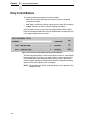
The resulting mapping table in Figure 33 allows you to keep track of printed
labels.
Figure 33. Creating a Forms Counter Entry
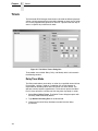
Reports
Reports are messages that can be sent to a number of destinations in the
printer. A report is created by specifying one or more sections and by
indicating the sequence in which these sections should be combined to form
the report. Depending on the destination it may be required to indicate how
long the report will be active.
Figure 34. The Define Reports Dialog Box
39
Chapter
2
Reports
Defining Reports
Continuing with the previous example, we want to receive a message on the
printer’s front panel LCD that all forms have been printed.
To define a report do the following:
1. Select EditDefine Reports. The Define Reports dialog box opens with
the Report tab active (Figure 34). Two tabs are available, the Report and
Sections tabs.
Figure 35. The Sections Tab of the Define Reports Dialog Box
2. Click the Sections tab (Figure 35). We will use this tab to define all
sections needed to make the full report. The printer front panel LCD is
has a maximum of 16 characters available per line to display the
message.
40
Creating Sections
Creating Sections
In continuing with the example, let us define the message as ‘ALL DONE
[xxxxx] where xxxxx represents the remaining count. This divides the report in
four sections:
•
•
•
•
# OF LABELS is the header section during printing
ALL DONE [ is the header used when all printing is done
xxxxx is the forms counter data field content
] ends the section.
Figure 36. Defining a Header Section
1. Type Header While Printing in the Name field.
2. Select Static String in the Type drop down menu.
3. Type # OF LABELS in the data pane.
4. Click Add. The Header section is added to the Item List pane (Figure 36).
5. Click the New button and type Header When Done Printing in the Name
field to define a second section.
6. Select Static String in the Type drop down menu.
7. Type ALL DONE [ in the data pane.
41
Chapter
2
Reports
8. Click Add. The Header When Done Printing section is added to the Item
List pane.
9. Click the New button and type Forms Count in the Name field to define a
third section.
10. Select Data Field in the Type drop down menu.
11. Select Value as the Format.
12. Click Add. The Forms Count section is added to the Item List pane.
Figure 37. Creating a Sections Item List
13. Click the New button and type End in the Name field to define a fourth
section.
14. Select Static String in the Type drop down menu.
15. Type ] in the data pane.
16. Click Add. The End section is added to the Item List pane (Figure 37).
42
Creating Reports
Creating Reports
We want to generate two reports using the sections just created. One report
to generate during printing and the other to generate after printing is
complete.
The first report, Label Count, is created with two sections: Header While
Printing and Forms Count. This will give the following text on the LCD:
# of Labels xxxx, where xxxx is the remaining label count.
The second report, Label Printing Done, is created with three sections:
Header When Done Printing, Forms Count, and End. This will give the
following text on the LCD: ALL DONE [xxxx] where xxxx is the remaining label
count.
Figure 38. Adding Available Sections
1. Click the Report tab.
2. Type Label Count in the Name field.
3. Click the Header While Printing section under Available.
4. Click the < button to add the Header section.
5. Click the Label section under Available.
6. Click the < button to add the Label Count section.
7. Click the Add button. Label Count is added to the item list (Figure 38).
43
Chapter
2
Reports
Figure 39. Adding Sections to a Report
8. Click the New button.
9. Type Label Printing Done in the Name field.
10. Click Header When Done Printing under Available.
11. Hold the Control key and click Label Count and End under Available.
12. Click the < button to add the Header When Done Printing, Label Count,
and End sections.
13. Click the Add button. Label Printing Done is added to the item list.
See Figure 39.
14. Click OK to close the dialog box.
44
Using Reports
Using Reports
To make sure the correct report is transmitted to the front panel LCD, add the
following entry to the mapping table.
Figure 40. Defining Entries in the GPIO Manager
Once the report has been defined and the Send Report action has been
selected, the parameter block allows you to specify what is to be done with
this report.
The Source drop down menu allows you to select a report previously created.
The Destination options tell the system where to transmit the report. The
Seconds field sets the time the report will be visible (applicable only to the
front panel LCD). See Figure 40.
45
Chapter
2
Timers
Timers
The Advanced GPIO Manager allows timers to be used for different purposes.
A timer can be programmed to create a delay between an event and an action
or it can be programmed to generate an event at a specific time each day or
even at a specific day and time each week.
Figure 41. The Define Timers Dialog Box
Three modes are available: Delay, Daily, and Weekly which is discussed in
the following sections.
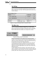
Delay Timer Mode
The Delay mode allows you to delay an action by a specified amount of time.
For example, a printer is used on a production line and the operator is
responsible for reloading ribbon when the printer runs out of ribbon. The
operator normally requires approximately 1.5 minutes to replace the ribbon
but if it takes more than 2 minutes we want the printer to prompt an action.
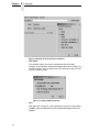
1. Select EditDefine Timers. The Define Timers dialog box opens with
the Delay mode selected by default.
2. Type Ribbon Reloading Error in the Name field.
3. Checkmark the Initial Delay checkbox to enable the initial delay
parameters.
46
Delay Timer Mode
4. Enter 2 in the MM field under Initial Delay.
This specifies a two minute initial delay in which the operator has two
minutes to reload ribbon. If the operator is able to change the ribbon and
place the printer online within two minutes, the delay timer stops. If the
operator is unable to change the ribbon within the two minutes, then the
delay timer starts and the printer gives a warning. The delay timer will
repeat for a specified amount of time until the error is cleared.
5. Enter 10 in the SS field under Delay.
If the operator is unable to change the ribbon within two minutes as
specified in the previous step, then the delay timer starts in 10 seconds.
In 10 seconds the printer will give a warning. The warning will repeat
every 10 seconds until the error is cleared.
6. Click Add. The Ribbon Reloading Error delay timer is added to the Timer
list. See Figure 42.
7. Click OK.
Figure 42. Setting a Delay Timer
47
Chapter
2
Timers
Daily Timer Mode
To generate an event at a specific time each day, use the Daily timer mode.
For example, you may want the printer to send a status report to the host
system everyday at 12:45 p.m. The status report can include a number of
datafields that keep track of paper, ribbon, or number of labels printed, etc.
To program the timer to generate the status report, do the following.
1. Select EditDefine Timers.
2. Type Daily Status in the Name field.
3. Select Daily as the mode.
4. Enter 12 in the Hour field and 45 in the Minute field.
5. Make sure the Repeat box is checkmarked. This ensures that a status
report will be sent everyday at 12:45 p.m.
If you want to specify a certain amount of days for the printer to send a
status report, uncheck the Repeat box and enter a value in the
Occurances field. For instance, to have the printer send a status report for
only five days, uncheck the Repeat box and enter 5 in the Occurances
field.
6. Click Add. The Daily Status timer is added to the Timer List.
See Figure 43.
7. Click OK.
Figure 43. Setting a Daily Timer
48
Weekly Timer Mode
Weekly Timer Mode
To generate an event on a specific time and day, use the Weekly timer mode.
In continuing with the previous example, if you want the printer to generate a
report to the host printer on certain days of the week at the same time, do the
following.
1. Select EditDefine Timers.
2. Type Weekly Status in the Name field.
3. Select Weekly as the mode.
4. Enter 12 in the Hour field and 45 in the Minute field.
5. Checkmark Monday and Friday. This specifies that an event will occur at
12:45 p.m. on Mondays and Fridays each week.
If you want to specify a certain amount of weeks for the printer to send a
status report, uncheck the Repeat box and enter a value in the
Occurances field. For instance, to have the printer send a status report for
only five weeks, uncheck the Repeat box and enter 5 in the Occurances
field. For this example, the printer sends a status report to the host printer
on Mondays and Fridays at 12:45 p.m. for the next five weeks.
6. Click Add. The Weekly Status timer is added to the Timer List.
See Figure 44.
7. Click OK.
Figure 44. Setting a Weekly Timer
49
Chapter
2
Timers
Using Timers
Figure 45. Using Timers to Activate an Alarm
When there is a ribbon error, the “On Ribbon Error” timer starts (Figure 45).
First there is a two minute initial delay for the operator to change the ribbon. If
the initial delay expires, it generates a timer expired event in which relay 1
activates. Relay 1 is set to sound an alarm. With a one second delay we make
sure the relay is activated for only a short time. After 10 seconds, if the ribbon
error is still there, the alarm sounds again. This will continue until the ribbon
error is cleared at which time we will stop the “On Ribbon Error” timer and will
deactivate relay 1.
Figure 46. Using Daily Timers
To set a daily status timer, we define two data fields:
•
Labels Printed – keeps track of the number of labels printed by
incrementing the data field for each label printed.
•
Paper Jams – keeps track of the number of paper jams by incrementing
the data field for each paper jam.
Daily at 12:45 we want to transmit the number of printed labels and paper
jams to the host. The format for this information should be
“Labels printed: {number};Ribbons used: {number}[CR][LF]”. Based on a
number of sections, we create a report called Daily Status Report.
See Figure 46.
50
Using Timers
Once defined, the timer needs to start at power-up. GPIO uses its own timer
based on the Real Time Clock. During the day, the data fields are updated for
each label printed and each paper jam occurrence. As soon as the timer
expires, the daily status report transmits to the printer.
For a weekly status report, set the timer setting to transmit the report weekly.
51
Chapter
52
2
Timers
3
Mapping
Download Mapping Tables
Once the mapping table has been designed and tested using the GPIO
testbox it must be downloaded to the printer. This can be done in three ways:
Method 1: Using Normal Download Mode
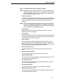
1. Save the mapping table from within the GPIO manager using the default
file name extension. This creates a downloadable file.
2. Set the printer in download mode (power-on with Menu and Down key
pressed)
3. Send the file to the printer in a DOS box (also called Command Prompt);
type copy/b filename.ext lpt1.
Method 2: Using RMS/PPM
1. Save the mapping table from within the GPIO Manager using the default
file name extension. This creates a downloadable file.
2. Attach the saved file as a download file to a printer and use the upgrade
utility.
Once downloaded, the printer resident GPIO event parser detects the file and
enables GPIO.
Method 3: Using the GPIO Download Facility
1. Click the Download
button on the GPIO toolbar.
2. Enter the required passwords for the GPIO program file and/or the
communication sessions.
3. In the connection tab, specify the access method and configure the
network or serial modem (if applicable).
4. Click OK to download the active mapping table(s) to the printer.
Once the mapping table is downloaded, the printer resident GPIO event
parser will detect the file and enable GPIO.
53
Chapter
3
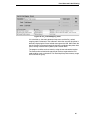
Preloaded Table
Preloaded Table
If a GPIO board is installed in the printer but no user defined mapping table
has been loaded, the printer will revert to a preloaded table.
Simple printer menus allow for programming three of the 11 (seven outputs,
four inputs) pre-defined interface signals to a particular polarity or logic
function that meets all typical print and apply requirements. They can also be
compatible with all the features available on other manufacturers’ external I/O
interfaces. This allows easy migration of Printronix T5000e or T5000r printers
to new or existing systems. Field interface is accomplished through an
industry standard 50-pin D type connector.
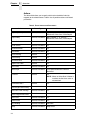
Input
Notes
1
Reprint
Requires 16 Mbyte Printer Memory Option
2
Start Print
Polarity programmable via printer menu
3
Feed
4
Pause
5..8
Output
54
Function
Not Used
Function
Notes
1
Ribbon Low
2
Ribbon Out
3
Media Out
4
Error/Service Required
5
End Print
8 modes selectable via printer menu
6
Data Ready/On Line
Selectable via printer menu
7
Not Used
8
Power On
Indicator Lights Example
Mapping Examples
Indicator Lights Example
Imagine a factory floor with a number of printers. Over each printer are
mounted lights that are controlled by the GPIO interface. The lights indicate
the printer’s status with the following conditions:
Green
Orange
Yellow
Red
Light
Conditions
Green
Printer online, waiting for a print job or is currently
printing, no warnings
Green and Orange
Ribbon low warning, printing continues
Green and Yellow
Label waiting for operator remove, printing
stopped
Red
Printer offline, no errors
Red and Orange
Printer offline, ribbon out
Red and Yellow
Printer offline, paper out
The following table shows all input required for printer control, hardware
interface, and connection.
Figure 47. Setting Events and Actions for Printer Control
55
Chapter
3
Mapping Examples
The connections made on the printer’s I/O connector are displayed in the
diagram below.
Figure 48. I/O Connections
Applicator Example
Imagine that a printer is connected to an applicator. When the printer has a
label ready for the applicator to handle, it signals this event by activating one
of the outputs. As soon as the applicator takes the label, the signal to the
applicator will be removed until the next label is present. This way a simple
interface connection between an applicator and printer is established. If any
printer error occurs, relay 1 will activate and result in additional action. Once
the problem is solved, placing the printer online clears the error report and
printing can start again.
Figure 49. Setting Events and Actions for Print and Apply
56
Protected Printer Example
Protected Printer Example
To protect the printer’s configuration from being overwritten, disable the front
panel buttons that are not used daily. The Online and Feed buttons should
remain active while the rest disabled. The mapping table listed in Figure 50
shows this function.
If the GPIO board is installed in the printer these functions may be rendered
inactive by deactivating the event parser using a special connector. If the
connector is installed, the event parser is disabled and the panel functions as
a panel on a printer. This allows service engineers access to all printer
configurations. Once the connector is removed the panel remains protected.
Figure 50. Setting Events and Actions to Disable Front Panel Keys
If the two last entries in the mapping are entered, the following connector
wiring results in a tool that can be used to enable or disable the normal front
panel functions.
Figure 51. Connector Wiring for Protected Printers
57
Chapter
3
Mapping Examples
Panel Selected Label Printing
Imagine that the requirement is to print one of three labels without host
intervention. To do this, the operator needs to have a selection mechanism at
the printer.
For this application, store the three labels (PGL files) in the printer. The three
labels named label_1, label_2, and label_3 sit in the printer waiting for the
~EXECUTE command.
The mapping table in Figure 52 disables the Menu and Enter keys, reassigns
the Feed function to the Down key, and the – key as the original Feed key.
The + key sends the following data streams to the host via the serial port:
•
•
•
the – key sends ~EXECUTE;Label_1;1<T><T>~NORMAL<T>
the Feed key sends ~EXECUTE;Label_2;1<T><T>~NORMAL<T>
the + key sends ~EXECUTE;Label_3;1<T><T>~NORMAL<T>
For more information, refer to the PGL Programmer’s Reference Manual.
The mapping also creates the possibility of changing this modified printer into
a normal one by plugging in the special connector from the Protected Printer
example on page 57.
Figure 52. Panel Selected Label Printing Mapping Table
When port switching is enabled, the serial port is the only port with which the
printer can communicate to itself. To make the printer communicate to itself a
special serial connector is required that connects the transmit data output to
the receive data input. When one of the three front panel buttons is pressed,
the printer receives a message through the serial port sent out of that serial
port by the same printer.
The serial connector in 25 pin and 9 pin is displayed in Figure 53.
58
Panel Selected Label Printing
Figure 53. 25 Pin and 9 Pin Serial Connectors
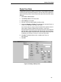
Once the PGL files and GPIO mapping table have been downloaded, and the
special serial connector is installed on the printer, the printer will print label_1
when the – key is pressed, label_2 when the Feed key is pressed, and
label_3 when the + key is pressed. The printer performs a form feed when the
Down key is pressed. The Menu and Enter keys are non-functional.
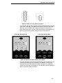
Panel with GPIO Disabled
Panel with GPIO Enabled
Figure 54. Panels with GPIO Disabled and Enabled
This works without the GPIO board installed in the printer; all it requires is the
specially wired connector at the serial port. As indicated, it could also be
combined with the Protected Printer example (see page 57). A connector
placed at the GPIO port could disable all this and allow a service engineer to
work on the printer without restrictions.
59
Chapter
3
Pin Code Protected Printer
Pin Code Protected Printer
The printer configuration protection described in the example on page 57
requires a special connector to disable GPIO so a service or application
engineer can work on the printer without restrictions. The special connector
requires one of the inputs to be specifically saved for protection purposes.
You can use software to protect the printer using a PIN code that can be
entered through the front panel.
Imagine that the panel is partly disabled and the Online key, the Feed key and
the Menu key are the only keys active. The Pause and Feed keys are
operational because they are required for daily printer operation. The Menu
key does not allow the user to open the configuration menu, instead it will ask
for a PIN code before allowing the user to change the configuration.
For this application the front panel keys get a value between 1 through 7
assigned to them using a datafield. A three digit PIN code allows any value
between 111 through 777 to be used. For example, the assignment list
include:
Panel Key
Number Assigned
Pause
1
Minus
2
Feed
3
Plus
4
Menu
5
Down
6
Enter
7
We’ll use three more data fields named new_pin, pin_number and
pin_entry_count. The pin_number data field contains the actual PIN number
required to enable the configuration. The final result of entering code will be
compared with this data field. If the codes and data fields match, the
configuration will be enabled. If they do not match, the user is allowed two
more chances. After that a message is sent to the host and the printer locks
up. Use the new_pin data field to create the PIN number.
On each entry we’ll send a message to line 2 of the LCD. For this example
we’ll use three messages with the following content:
•
•
•
60
message one_pin contains ‘*--’
message two_pin contains ‘**-’
message three is either ‘PIN accepted’ or ‘PIN incorrect’
Panel Selected Label Printing
When a key is pressed, the value of the corresponding data field is added to
the value in new_pin (which initially contains 0). If the down key is pressed,
new_pin now contains 6. If this is not the last (third) entry, the content of
new_pin is multiplied by 10 (effectively shifting it over 1 decimal place). The
message one_pin is sent to the LCD that now shows ‘PIN number: *--‘.
If the Feed key is pressed next, the value in the related data field (3) is added
to new_pin which now contains 63. Again, it is not the last entry so new_pin is
multiplied by 10, the content changes to 630 and the message two_pin is sent
to the LCD to show ‘PIN number: **-‘.
If the Menu key is the third and last key pressed, the value 5 is added to
new_pin. The content is now 635. Since this is the last key the number will not
be multiplied by 10. Instead, we will send a message to the LCD. We now
have the complete PIN code entered, compare it with the PIN code stored in
the printer. This is done by a simple comparison of two data fields, new_pin
and pin_number.
If the values match we’ll make all keys available to the user. If the values don’t
match we’ll increase the ‘pin_entry_count’ by one and start over. If the
‘pin_entry_count’ reaches three some message will be transmitted to the host
and the complete panel will be blocked.
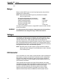
Data Fields, Reports, and Timers
The following (U16) data fields need to be created for this application where
the content of the pin_number data field can be any value between 111 and
777.
Data Field Name
Initial Value
Pause_Key
1
Minus_Key
2
Up-Key
3
Plus_Key
4
Menu_Key
5
Down_Key
6
Enter_Key
7
Pin_Entry_Count
0
New_Pin
0
Pin_Number
635
61
Chapter
3
Pin Code Protected Printer
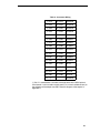
Next to the data fields are status reports and information sent to the host if
there is an error. The six reports listed in Table 5 need to be generated. Each
report only has a single section that may have the same name as the report.
Table 5. Report Names, Sections, and Content
Report Name
Section Name
Content
pin_empty
pin_empty
PINumber:---
one_pin
pin_1
PINumber:*--
two_pin
pin_2
PInumber:**-
pin_accepted
pin_ok
PIN accepted
incorrect_pin
pin_error
PIN incorrect
locked
locked
*Printer Locked*
The PIN number appliction is described by reviewing each of the mapping
tables and explaining each entry in that table.
Tables
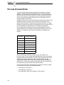
Figure 55. Power_On Mapping Table
Table 5 does not show all entries in a power-on table, just those that are
important for the PIN number application. The first four entries disable the
important keys by “consuming” the key function, that is, the action that
normally would result from pressing the key will not execute. The Pause and
Feed key are left unchanged but as soon as the menu key is pressed the
specified actions execute. First the original function is consumed, then the
pin_empty message displays in Line 2 of the LCD, and the pin_part_1
mapping table is selected.
62
Panel Selected Label Printing
Figure 56. Pin_Part_1 Mapping Table
If a key is pressed for the first 7 entries, the value of the related data field is
added to the new_pin data field, which is multiplied by 10 to shift the content
one decimal place over. Since we now have the first part of the PIN number in
a data field, we’ll display the one_pin message on the LCD and switch to the
pin_part_2 table.
Figure 57. Pin_Part_2 Mapping Table
The Pin_Part_2 mapping table is similar to the Pin_Part_1 mapping table. If a
key is pressed for the first 7 entries, the value of the related data field is added
to the new_pin data field, which is multiplied by 10. The message two_pin will
display to indicate that two numbers of the PIN code have been entered and
to select the pin_part_3 table.
63
Chapter
3
Pin Code Protected Printer
Figure 58. Pin_Part_3 Mapping Table
The Pin_Part_3 mapping table starts with the same seven entries. The value
is added to new_pin but this time we do not multiply the value by 10; we now
have the complete PIN code. The message displayed depends on the result
of the comparison beween the new_pin data field and the pin_number data
field. If the two values are the same, the message pin_accepted will display
and GPIO will be disabled, allowing the printer to function as a normal printer.
Configuration changes can be made and saved. A power cycle is required to
reactivate GPIO and its printer protection function.
If the two numbers do not match the pin_incorrect message displays on the
LCD. The printer will beep three Times New Roman and the pin error count
increments. This value is tested to see if this was the third trial. If not, the user
is given another try.
64
Panel Selected Label Printing
Figure 59. Prt_Locked Mapping Table
If it is the third try, the event generator timer starts and the Prt_Locked
mapping table is selected. In this table we’ll inform the user that the printer is
locked by displaying the Printer Locked message on the LCD. We’ll inform the
host by sending a message through the interface and disable the printer front
panel, making it useless until a power cycle has been done.
The program could be easier to enter by using the new subroutine function.
The seven entries related to the pressing of the keys to generate the PIN
code could be made a subroutine. This would improve printer memory usage
and save time on typing.
65
Chapter
66
3
Pin Code Protected Printer
A
Technical Information
Opto-couplers
The opto-couplers are Vishay SFH6916 or equivalent with the following basic
specifications:
NOTE: Please check the Vishay SFH6916 datasheet for electrical
specifications.
GaAs Light Emitting Diode
Reverse Voltage (Vr)
Forward Current (DC)
Peak Forward Current (Ifp)
NPN Silicon Phototransistor
Isolation Voltage (Vr)
Collector to Emitter voltage (Vceo)
Collector current
High switching speed
UL approved
:6V
: 50 mA
: 2.5 A
: 3750 V r.m.s.
: 70 V
: 50 mA
The inputs of the GPIO board (the LEDs of 8 opto-couplers) are protected
against overcurrent by the inclusion of a 4700 Ohm resistor in the anode
connection. This allows for an input voltage range between 5 and 24 VDC.
The opto-coupler outputs are open collector transistors. By design the output
current available is set at 3 ma. max. This value is based on an opto-coupler
current transfer ratio of 100% at an ambient temperature of 50 degrees C.
Load currents greater than 3 ma. will cause the transistor to come out of
saturation, resulting in a rise in the output voltage and possible damage to the
transistor.
WARNING
For safety purposes a volate no greater than 42 volts DC should be
applied to the GPIO board.
The GPIO board has a provision for mounting resistors, either in the
connection between the actual output pin and the collector of the output
transistor or from a common connector pin (17) to the collector of the output
resistor. See the drawing in Appendix C.
67
Appendix A
Relays
Relays
Relays are the NAiS TX type and are 2-Amp high capacity relays with the
following basic specifications:
NOTE: Please check the NAiS TX type relay datasheet for complete
electrical specifications.
Surge withstand between coil and contacts
Breakdown voltage between coil and contact
Nominal switching capacity
Maximum switching voltage
Maximum switching current
Contact settling time
: 2500 V
: 2000 V
: 2 A @ 30 V
: 220 V DC
:2A
: 4 mS (max)
The relays are type DPDT of which a single SPDT contact is made available
on the I/O connector.
WARNING
For safety purposes do not apply a voltage greater than 42 volts DC to
the GPIO board even though the relay is rated at 220 volts DC.
Voltages
Two voltages available on the I/O connector are 5 and 24 volts DC. Using
self-healing fuses, both voltages are separately fused at 500 mA for 5 volts
and 250 mA for 24 volts. These voltages share the same ground. To
guarantee complete galvanic isolation between the printer and the equipment
that is connected through the GPIO interface, use a separate power source
for the equipment the printer is connected to and make sure the I/O connector
housing on the printer side is not connected to ground.
NOTE: Be aware that the 24 volts require a special connection inside the
printer and that this voltage is not available when a cutter is installed
in the Thermal printer.
I/O Connector
The I/O connector is a 3 row, 50 pin, D type connector. Inputs and outputs of
opto-couplers and relays are wired to this connector so that creating inputs
using common anodes or cathodes or outputs using common emitters or
collectors is fairly simple. The two voltages and their respective returns are
also wired to this connector.
Table 6 specifies the connector wiring where IPxA represents the anode
connection of the Input Opto Coupler diode and IPxC represents the cathode
connection of the diode. OPxC represents the collector of the output
transistor, and OPxE represents the emitter of the transistor. RxCM
represents the common connection of the SPDT relay contact, RxNC
represents the Normally Closed, and RxNO the Normally Open contact.
68
Table 6 : Connector Wiring
1: IP1A
18: OP1C
34:R1CM
2: IP2A
19: OP2C
35:R2CM
3: IP3A
20: OP3C
36:R3CM
4: IP4A
21: OP4C
37:R4CM
5: IP5A
22: OP5C
38:R1NC
6: IP6A
23: OP6C
39:R2NC
7: IP7A
24: OP7C
40:R3NC
8: IP8A
25: OP8C
41:R4NC
9: IP1C
26: OP1E
42:R1NO
10: IP2C
27: OP2E
43:R2NO
11: IP3C
28: OP3E
44:R3NO
12: IP4C
29: OP4E
45:R4NO
13: IP5C
30: OP5E
46: n.c.
14: IP6C
31: OP6E
47:+5V
15: IP7C
32: OP7E
48:5Vret
16: IP8C
33: OP8E
49:+24V
17:
(*)
50:24Vret
(*) Pin 17 is connected to a number of through holes on the GPIO printed
circuit board. It can be used to supply power (via a user-installed resistor) to
the collectors of the output transistors. See the diagram of the outputs in
Appendix C.
69
Appendix A
70
I/O Connector
15
2
5V Ret
16
13
4
1
14
11
12
9
10
15
16
13
3
6
5
8
7
2
1
4
14
11
6
3
12
9
5
8
Printronix
Expansion
Bus Control
Logic
All anode protection resistors are 4.7K Ohms.
IP8C
IP8A
IP7C
IP7A
IP6C
IP6A
IP5C
IP5A
IP4C
IP4A
IP3C
IP3A
IP2C
IP2A
IP1C
10
RY0
RY1
RY2
7
RY3
IP1A
11 OP2F
14 OP3C
13 OP3F
16 OP4C
15 OP4F
10 OP5C
OP5F
6
3
4
1
2
7
8
13 OP7F
16 OP8C
15 OP8F
4
1
2
5V Ret
14 OP7C
3
OP6C
11 OP6F
12
6
5
12 OP2C
5
9
9
8
OP1F
10 OP1C
7
5
RY2
+5V
9
3
RY1
RY3
1
RY0
OP1C
OP2C
OP3C
OP4C
OP5C
OP6C
OP7C
OP8C
IP1A
IP2A
IP3A
IP4A
IP5A
IP6A
IP7A
IP8A
IP1C
IP2C
IP3C
IP4C
IP5C
IP6C
IP7C
IP8C
1
2
3
4
5
6
7
8
9
10
11
12
13
14
15
16
17
18
19
20
21
22
23
24
25
26
27
28
29
30
31
32
33
34
35
36
37
38
39
40
41
42
43
44
45
46
47
48
49
50
+5V
5V RET
+24V
24V RET
R3N0
R4N0
R1N0
R2N0
OP1F
OP2F
OP3F
OP4F
OP5F
OP6F
OP7F
OP8F
R1COM
R2COM
R3COM
R4COM
R1NC
R2NC
R3NC
R4NC
K1
K2
K3
K4
K4
K3
K2
K1
1
1
1
1
2
2
2
2
Relays: NAI5 TX2
R4NO
R4NC
R4COM
R3NO
R3NC
R3COM
R2NO
R2NC
R2COM
R1NO
R1NC
R1COM
B
Basic GPIO Schematic
Diagram
71
Appendix B
72
C
Electrical Inputs And
Outputs
GPIO Opto-coupled Input Circuit
Opto-coupler
+
4700 Ohm
Input voltage range 5..24 VDC
-
GPIO Opto-coupled Output Circuit
Pin 17
+
Opto-coupler
Active Low Output
Factory installed jumpers
+
Current Limited Output
Load
Factory Default Configuration
User Selectable Configurations
73
Appendix C
74
GPIO Opto-coupled Output Circuit
D
Contact Information
Printronix Customer Support Center
IMPORTANT
Please have the following information available prior to calling the
Printronix Customer Support Center:
•
•
•
•
Model number
Serial number (located on the back of the printer)
Installed options (i.e., interface and host type if applicable to the problem)
Configuration printout:
Thermal Printer
See “Printing A Configuration” in the Quick Setup Guide.
Line Matrix Printer
Press PRT CONFIG on the control panel, then press Enter.
•
•
•
Is the problem with a new install or an existing printer?
Description of the problem (be specific)
Good and bad samples that clearly show the problem (faxing or emailing
of these samples may be required)
Americas
(714) 368-2686
Europe, Middle East, and Africa
(31) 24 6489 311
Asia Pacific
(65) 6548 4114
China
(86) 800-999-6836
http://www.printronix.com/support.aspx
75
Appendix D
Printronix Supplies Department
Printronix Supplies Department
Contact the Printronix Supplies Department for genuine Printronix supplies.
Americas
(800) 733-1900
Europe, Middle East, and Africa
33 (0) 1 46 25 19 07
Asia Pacific
(65) 6548 4116
or (65) 6548 4182
China
(86) 400-886-5598
India
(800) 102-7869
http://www.printronix.com/supplies-parts.aspx
Corporate Offices
Printronix, Inc.
15345 Barranca Parkway
Irvine, CA 92618
U.S.A.
Phone: (714) 368-2300
Fax: (714) 368-2600
Printronix Inc.
c/o Printronix Nederland BV
Bijsterhuizen 11-38
6546 AS Nijmegen
The Netherlands
Phone: (31) 24 6489489
Fax: (31) 24 6489499
Printronix Schweiz GmbH
42 Changi South Street 1
Changi South Industrial Estate
Singapore 486763
Phone: (65) 6542 0110
Fax: (65) 6546 1588
Printronix Commercial (Shanghai) Co. Ltd
22F, Eton Building East
No.555, Pudong Av.
Shanghai City, 200120, P R China
Phone: (86) 400 886 5598
Fax: (86-21) 5138 0564
Visit the Printronix web site at www.printronix.com
76
Index
A
Actions, 8, 17, 24
G
GPIO
descriptions, 26
entry fields, 15
multiple, 31
hardware, 8
Applicator Example, 56
menus, 10
B
Opto-coupled Input Circuit, 73
Opto-coupled Output Circuit, 73
Basic GPIO Schematic Diagram, 71
overview, 9
C
Contact information, 75
H
Hardware, 8
Customer Support Center, 75
I
D
I/O Connector, 68
Daily Timer Mode, 48
Indicator Light Example, 55
Data Field Actions, 34
M
Data Field Events, 34, 37
Data Fields, 33
Manual Overview, 7
Delay Timer Mode, 46
Mapping
Diagram, Basic GPIO Schematic, 71
applicator example, 56
Download Mapping Tables, 53
examples, 55
E
indicator light example, 55
protected printer example, 57
Entry Control Buttons, 30
Mapping Tables, download, 53
Entry Fields, 15
Menus, 10
Events, 8, 17
Multiple Actions, 31
descriptions, 18
O
F
ON Flag, 32
Fields, data, 33
Opto-coupled input circuit, 73
Flag, ON, 32
Opto-coupled output circuit, 73
Opto-couplers, 67
Overview, manual, 7
77
P
Panel Selected Label Printing, 58
Pin Code Protected Printer, 60
Preloaded Table, 54
Printer, pin code, 60
Printing, panel selected label, 58
Protected Printer Example, 57
R
Relays, 68
Reports, 39
create, 43
define, 40
sections, 41
use, 45
S
Sections, 41
create, 41
Status Line, 32
Supplies Department, 76
T
Table, preloaded, 54
Technical Information
I/O connector, 68
opto-couplers, 67
relays, 68
voltages, 68
Timers, 46
daily timer mode, 48
delay timer mode, 46
usage, 50
weekly timer mode, 49
U
Using Reports, 45
Using Timers, 50
V
Voltages, 68
78
W
Weekly Timer Mode, 49
*250424-001*
250424-001D