1
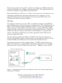
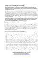
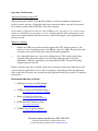
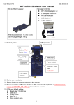
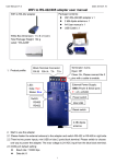
ELECRAFT Application Note
Using Virtual Serial Ports with Logging and Contest Software
Revision B2, August 14, 2015
Copyright © 2015, Elecraft, Inc.; All Rights Reserved
Introduction
Many contact and contest logging programs require the use of dual COM ports at the host
computer for transceiver control and keying. This Application Note introduces methods for
concentrating multiple computer COM ports to a single transceiver serial port, using COM Port
Concentrator (CPC) software. An example is used for illustration purposes.
A typical CPC scenario consists of one computer COM port used for keying and PTT, with
another COM port used for remote control. The transceiver, of course, only has a single port.
The transceiver port may be implemented as plain RS232, via a USB-serial adapter, or less often
via other interfaces such as Ethernet or Wi-Fi. The CPC software binds the two computerinternal (virtual) COM ports into a single externally-accessible physical serial port. The two
virtual ports are used by the logging program, while the single physical port is connected to the
transceiver.
Scope
This App Note is written for Amateurs that require detailed knowledge about COM port
concentrators and the configuration of logging programs. The example used is specific to the
Elecraft K3S and K3, but nearly all concepts presented also apply to other Amateur transceivers
that have serial ports.
This Note is limited to the use of Microsoft Windows™ and application software designed for
that operating system.
CPC Types
There are two types of CPCs: Polling and Direct. A polling CPC continuously queries the
transceiver for its state (frequency, mode, etc.) and maintains a local copy or “cache” to use in
reply to the logger application’s queries. A direct CPC doesn’t maintain a local copy of the
transceiver’s state. Both types of concentrators support the modem control signals DTR and
RTS, used in keying and PTT at the transceiver. A polling CPC is always designed to work with
a specific serial port-based device type (say, a K3). A direct CPC is device-agnostic.
An example of a polling CPC is LP Bridge, a software program developed and maintained by
Telepost, Inc. LP Bridge is a full-featured CPC that was designed to work with the Elecraft K3S
and K3 transceivers.
Elecraft • www.elecraft.com • 831-763-4211
Technical content subject to change without notice
For more information, please contact: [email protected]
There are many examples of direct CPCs. One that is in common use is VSPE, developed and
maintained by Eterlogic.com. VSPE is a full-featured direct CPC. This Application Note does
not show any examples of using VSPE, to keep the Note brief.
Because the polling type of CPC acts as a “stand in” for the transceiver, it is the best type to use
with multiple applications that each interact with the transceiver’s control port. If your
application needs one port for data and another port for keying and/or PTT, either type of
concentrator will suffice, if properly configured.
CPC Usage
One of the more common use cases for a CPC is to combine the computer’s keying/PTT and
control COM ports into a single serial port for use at the transceiver. This is illustrated below in
Figure 1 and described here. In this configuration, COM11 is used for serial communications
with the transceiver, while COM12 is used as the transceiver’s keying and PTT port. COM8,
shown on the right, is the physical serial port that is connected to the transceiver. COM11 and
COM12 aren’t physical serial ports, but instead are virtual COM ports created by the CPC
software. They become available for use by software applications after the CPC has been
correctly configured and started.
The CPC application combines the COM11 and COM12 streams from the computer to the
transceiver port (COM8). Likewise, from the transceiver to the computer, the streams are split
so that both COM11 and COM12 ports receive identical data from the transceiver.
The application program used in the example of Figure 1 is N3FJP’s Amateur Contact Log
(ACL). The transceiver is set up in CW Mode, and the logger will be used to key it using the
KEY input via the serial port’s DTR modem control signal. LP Bridge is used as the CPC.
Figure 1. Virtual and physical serial port configuration, shown with a contact logger program
requiring two COM ports.
Elecraft • www.elecraft.com • 831-763-4211
Technical content subject to change without notice
For more information, please contact: [email protected]
Special Case: CPC Usage with a USB-Serial Adapter
When a USB-Serial adapter is plugged into your Windows PC or its external USB Hub, it is
enumerated as if it were a regular COM port. What’s needed is to understand which COM port
the USB adapter represents.
The Windows Control Panel provides access to Device Manager, an applet which is used to
probe details about various device types that Windows recognizes. Within Device Manager,
select the Ports category and expand it. As the USB-Serial adapter is inserted, a new COM port
will appear. When the adapter is removed, that same port will vanish from the lineup. Take note
of which COM port appears and vanishes. That port is the one to use as the physical port during
setup and configuration.
While in Device Manager, select two COM ports that aren’t listed in the lineup. These will be
used as the virtual ports - COM11 and COM12 in the example - in the CPC’s configuration.
Two ports with adjacent numbering are easiest to keep track of.
CPC Setup and Configuration
See Figure 2, below, which is based on the diagram shown in Figure 1. COM11 and COM12 are
the two virtual COM ports available to the contact logger application program. COM8 is shown
as the physical port, which is the RS232 or USB-serial adapter connection to the transceiver.
Setting up the CPC is described below, step by step, below. This sequence uses the LP Bridge
program from Telepost, Inc. as an example, but any CPC you use needs to be configured
similarly in order to work properly.
The steps needed to implement the example in LP Bridge are:
1. Select the K3 Com Port (see upper left panel). Use the drop-down menu to select the COM
port. The example uses COM8. If you want the program to connect to this physical COM
port automatically when it starts up, check the Auto Connect box. Now, push the Connect
button to connect the transceiver port. There is a short delay while LP Bridge makes the
connection. During this time, there is nothing visible happening with the program.
2. Select the PTT-Key port in the Virtual Com Port #1 panel (lower left). Use the drop down
menu to select the COM port to be used for PTT-Key – the first one chosen earlier. If you
want the program to create this virtual port automatically when it starts up, check the Auto
Create box. In the lower text box in this panel, you can label the virtual port for later
reference. Push the Create button to create the virtual serial port. Note that the example uses
COM12 for this step. There may be a brief delay while LP Bridge initializes the virtual port.
3. Repeat the last step, but use the Virtual Com Port #2 panel for the control port, and the
second virtual COM port from the two chosen earlier. Again, there is a text box available to
label how the port is to be used. The example uses COM11 for this step, and the label
indicates “Data Port”. There may be a brief delay while LP Bridge initializes the virtual port.
Elecraft • www.elecraft.com • 831-763-4211
Technical content subject to change without notice
For more information, please contact: [email protected]
4. Leave LP Bridge running to use with the next section.
Figure 2. Configuration example of LP Bridge. This configuration corresponds to Figure 1.
Logger Setup and Configuration
If you followed the steps in the last section, there are two virtual COM ports available for the
logger program. This example uses N3FJP’s Amateur Contact Log (ACL) to illustrate how to
set up a logger application to use the virtual COM port configuration already described. Other
logger programs have their own variations on the steps needed.
Please refer to Figure 3 and 4, on the following pages.
Key Setup
1. To configure the logger application to use the PTT-Key port, left click on ACL’s Settings
menu, then select Transmit => CW Setup. The display will show a setup form as in Figure 3.
2. Choose the PTT-Key port in the Com Port panel (top left). The PTT-Key virtual port was
already set up in LP Bridge. The example uses COM12.
3. Choose the Keying Options to the right of the Com port panel. The example uses DTR.
4. Push the Done button on the bottom of the CW Setup window.
Elecraft • www.elecraft.com • 831-763-4211
Technical content subject to change without notice
For more information, please contact: [email protected]
Note: For N3FJP Amateur Contact Log, to set up SSB or AM operation, use the Settings menu
under Transmit => Phone Setup. The standard PTT setting to use is RTS.
Figure 3. CW Setup screen in N3FJP’s Amateur Contact Logger.
Elecraft • www.elecraft.com • 831-763-4211
Technical content subject to change without notice
For more information, please contact: [email protected]
Rig Interface Setup
[See Figure 4, below.]
1. To set up the N3FJP logger application to read and write the control port, use the Select Rig
panel to choose the transceiver type. The example shows an Elecraft transceiver (K3S or
K3).
2. Next, choose the control port that you selected earlier. The example uses COM11.
3. Set the Baud Rate (the baud rate set up in the K3’s CONFIG:RS232 menu), then parity
(none), 8 data bits, 1 stop bit. If using an external USB (or the K3S’s internal USB), 38400
baud is recommended.
4. The Data Polling Rate is next. In this case, for K3-type rigs, 500 mS is generally adequate
and is known to function properly. Longer polling intervals may be used if buffer overruns
occur.
5. Push the Done button on the bottom of the CW Setup window.
Using the Logger
Now that you have the logger running with the transceiver, you may want to try out CW and
SSB modes. Most loggers, including N3FJP, have CW and voice message recording and
playback functions, and this type of facility is a great place to start. Record a few CW or voice
messages then use the F keys to play them back with the logger, with keying or PTT controlled
by the logger program. See your logger’s user manual for details on this type of operation.
Normally, the logger “tracks” the transceiver’s mode and band, rather than controlling it. Of
course, you may wish to change this. But for a first try, go ahead and change bands and / or
modes at the transceiver’s front panel. You should see the logger following along if the COM
port “plumbing” is working correctly.
Elecraft • www.elecraft.com • 831-763-4211
Technical content subject to change without notice
For more information, please contact: [email protected]
Figure 4. Rig Interface Setup screen in N3FJP’s Amateur Contact Logger (rotated image). The screen
capture aspect ratio has been altered slightly in order to fit the page size.
Elecraft • www.elecraft.com • 831-763-4211
Technical content subject to change without notice
For more information, please contact: [email protected]
Operating Considerations
Application Stacking using a CPC
When running with a K3/K3S plus the P3 panadapter, use the least number of applications
needed to get the job done. Each application does not know the others exist and will assume it
has exclusive control of the COM port(s) it has been assigned.
As the number of applications using the same COM port rises, the radio receives an increasing
number of commands it must attempt to execute. At some point, the radio cannot process and
reply to one command before the next one arrives. When this happens, some applications may
lock up or crash.
Methods to mitigate
•
Reduce the COM port speed between the output of the CPC and the transceiver. For
instance, if you’re attempting to run at 38,400 bps, lower it to 9600. This gives the radio
extra time to use in processing and replying to incoming commands.
•
For each Application in use, increase the polling interval. This setting controls how
frequently each application reaches out to the radio asking for status or updated
information. The more applications you stack behind the CPC, the more the polling
frequency must be lowered.
Failure to take the steps above typically results in lost data because the radio cannot process the
requests from the applications as fast as they’re coming in. Depending on how the application
reacts to the lack of response, the operator may find applications locked up, crashed, or otherwise
unresponsive.
Recommended Reading and Links
1. LP Bridge Overview and Web Manual:
http://www.telepostinc.com/LPB.html
2. VSPE Description and Information Page:
http://www.eterlogic.com/Products.VSPE.html
3. Eltima’s Virtual Serial Port Page:
http://www.eltima.com/products/vspdxp/
4. N3FJP Amateur Contact Log Page:
http://n3fjp.com/aclog.html
5. N1MM Contest Logging Software:
http://n1mm.hamdocs.com/tiki-index.php
Elecraft • www.elecraft.com • 831-763-4211
Technical content subject to change without notice
For more information, please contact: [email protected]