1
Agilent Technologies 8960 Series 10 E5515B Wireless Communications Test Set
Agilent Technologies E1960A GSM Mobile Test Application
Agilent Technologies E1964A GPRS Mobile Test Application
Reference Manual
GSM Test Application Revision A.05
GPRS Test Application Revision A.00
© Copyright Agilent Technologies 2000
Printed in U.S.A. October 2000
Agilent Part Number: E1964-90001
http://www.agilent.com/find/8960support/
Notice
Information contained in this document is subject to change without notice.
All Rights Reserved. Reproduction, adaptation, or translation without prior written permission is prohibited,
except as allowed under the copyright laws.
This material may be reproduced by or for the U.S. Government pursuant to the Copyright License under the
clause at DFARS 52.227-7013 (APR 1988).
Agilent Technologies, Inc.
Learning Products Department
24001 E. Mission
Liberty Lake, WA 99019-9599
U.S.A.
Legal Information
Legal Information
Manufacturer’s Declaration
This statement is provided to comply with the requirements of the German Sound Emission Directive, from 18
January 1991.
This product has a sound pressure emission (at the operator position) < 70 dB(A).
• Sound Pressure Lp < 70 dB(A).
• At Operator Position.
• Normal Operation.
• According to ISO 7779:1988/EN 27779:1991 (Type Test).
Herstellerbescheinigung
• Schalldruckpegel Lp < 70 dB(A).
• Diese Information steht im Zusammenhang mit den Anforderungen der
Maschinenlärminformationsverordnung vom 18 Januar 1991.
• Am Arbeitsplatz.
• Normaler Betrieb.
• Nach ISO 7779:1988/EN 27779:1991 (Typprüfung).
3
Legal Information
Safety Considerations
GENERAL
This product and related documentation must be reviewed for familiarization with safety markings and
instructions before operation.
This product has been designed and tested in accordance with IEC Publication 1010, "Safety Requirements
for Electronic Measuring Apparatus," and has been supplied in a safe condition. This instruction
documentation contains information and warnings which must be followed by the user to ensure safe
operation and to maintain the product in a safe condition.
SAFETY EARTH GROUND
A uninterruptible safety earth ground must be provided from the main power source to the product input
wiring terminals, power cord, or supplied power cord set.
SAFETY SYMBOLS
!
Indicates instrument damage can occur if indicated operating limits are exceeded.
Indicates hazardous voltages.
Indicates earth (ground) terminal
WARNING
A WARNING note denotes a hazard. It calls attention to a procedure, practice, or the
like, which, if not correctly performed or adhered to, could result in personal injury.
Do not proceed beyond a WARNING sign until the indicated conditions are fully
understood and met.
CAUTION
A CAUTION note denotes a hazard. It calls attention to an operation procedure, practice, or the
like, which, if not correctly performed or adhered to, could result in damage to or destruction of
part or all of the product. Do not proceed beyond an CAUTION note until the indicated conditions
are fully understood and met.
4
Legal Information
WARNING
This product is a Safety Class I instrument (provided with a protective earthing
ground incorporated in the power cord). The mains plug shall only be inserted in a
socket outlet provided with a protective earth contact. Any interruption of the
protective conductor inside or outside of the product is likely to make the product
dangerous. Intentional interruption is prohibited.
Whenever it is likely that the protection has been impaired, the instrument must be
made inoperative and be secured against any unintended operation.
If this instrument is to be energized via an autotransformer (for voltage reduction),
make sure the common terminal is connected to the earth terminal of the power
source.
If this product is not used as specified, the protection provided by the equipment
could be impaired. This product must be used in a normal condition (in which all
means for protection are intact) only.
No operator serviceable parts in this product. Refer servicing to qualified personnel.
To prevent electrical shock, do not remove covers.
Servicing instructions are for use by qualified personnel only. To avoid electrical
shock, do not perform any servicing unless you are qualified to do so.
The opening of covers or removal of parts is likely to expose dangerous voltages.
Disconnect the product from all voltage sources while it is being opened.
The power cord is connected to internal capacitors that my remain live for
5 seconds after disconnecting the plug from its power supply.
For Continued protection against fire hazard, replace the line fuse(s) only with 250 V
fuse(s) or the same current rating and type (for example, normal blow or time delay).
Do not use repaired fuses or short circuited fuseholders.
Always use the three-prong ac power cord supplied with this product. Failure to
ensure adequate earth grounding by not using this cord may cause product damage.
This product is designed for use in Installation Category II and Pollution Degree 2 per
IEC 1010 and IEC 664 respectively. FOR INDOOR USE ONLY.
This product has autoranging line voltage input, be sure the supply voltage is within
the specified range.
To prevent electrical shock, disconnect instrument from mains (line) before cleaning.
Use a dry cloth or one slightly dampened with water to clean the external case parts.
Do not attempt to clean internally.
Ventilation Requirements: When installing the product in a cabinet, the convection
into and out of the product must not be restricted. The ambient temperature (outside
the cabinet) must be less than the maximum operating temperature of the product by
4° C for every 100 watts dissipated in the cabinet. If the total power dissipated in the
cabinet is greater than 800 watts, then forced convection must be used.
5
Legal Information
Product Markings
CE - the CE mark is a registered trademark of the European Community. A CE mark accompanied by a year
indicated the year the design was proven.
CSA - the CSA mark is a registered trademark of the Canadian Standards Association.
CERTIFICATION
Agilent Technologies, Inc. certifies that this product met its published specifications at the time of shipment
from the factory. Agilent Technologies further certifies that its calibration measurements are traceable to the
United States National Institute of Standards and Technology, to the extent allowed by the Institute’s
calibration facility, and to the calibration facilities of other International Standards Organization members
WARRANTY
This Agilent Technologies instrument product is warranted against defects in material and workmanship for a
period of one year from date of shipment. During the warranty period, Agilent Technologies, Inc. will at its
option, either repair or replace products which prove to be defective.
For warranty service or repair, this product must be returned to a service facility designated by Agilent. Buyer
shall prepay shipping charges to Agilent and Agilent shall pay shipping charges, duties, and taxes for products
returned to Agilent from another country.
Agilent warrants that its software and firmware designated by Agilent for use with an instrument will execute
its programming instructions when properly installed on that instrument. Agilent does not warrant that the
operation of the instrument, or software, or firmware will be uninterrupted or error free.
LIMITATION OF WARRANTY
The foregoing warranty shall not apply to defects resulting from improper or inadequate maintenance by
Buyer, Buyer-supplied software or interfacing, unauthorized modification or misuse, operation outside of the
environmental specifications for the product, or improper site preparation or maintenance.
NO OTHER WARRANTY IS EXPRESSED OR IMPLIED. AGILENT SPECIFICALLY DISCLAIMS THE
IMPLIED WARRANTIES OF MERCHANTABILITY AND FITNESS FOR A PARTICULAR PURPOSE.
EXCLUSIVE REMEDIES
THE REMEDIES PROVIDED HEREIN ARE BUYER’S SOLE AND EXCLUSIVE REMEDIES. AGILENT
SHALL NOT BE LIABLE FOR ANY DIRECT, INDIRECT, SPECIAL, INCIDENTAL, OR CONSEQUENTIAL
DAMAGES, WHETHER BASE ON CONTRACT, TORT, OR ANY OTHER LEGAL THEORY.
ASSISTANCE
Product maintenance agreements and other customer assistance agreements are available for Agilent
Technologies products. For any assistance, contact your nearest Agilent Technologies Sales and Service Office.
6
Legal Information
DECLARATION OF CONFORMITY
According to ISO/IEC Guide 22 and CEN/CENELEC EN45014
Manufacturer’s Name:
Agilent Technologies UK Ltd.
Agilent Technologies, Inc.
Manufacturer’s Address:
Electronic Products & Solutions
Group - Queensferry
South Queensferry
West Lothian, EH30 9TG
Scotland, United Kingdom
24001 E. Mission Avenue
Liberty Lake
Washington
99019-9599
USA
Declares that the product
Product Name:
8960 Series 10 Wireless Communications Test Set
Model Number:
E5515B
Product Options:
This declaration covers all
options of the above product.
EMC:
Conforms with the following product specifications:
Standard:
CISPR11:1990 / EN55011:1991
IEC 801-2:1991 / EN 50082-1:1992
IEC 801-3:1984 / EN 50082-1:1992
IEC 801-4:1988 / EN 50082-1:1992
Limit:
Group 1 Class A
4kV CD, 8kV AD
3V/m, 27-500 MHz
0.5kV signal lines, 1kV power lines
Safety:
The product conforms to the following safety standards:
IEC 61010-1(1990) +A1(1992) +A2(1995) / EN 61010-1:1993
Canada / CSA-C22.2 No. 1010.1-93
The product herewith complies with the requirements of the Low Voltage Directive 73/23/EEC,
and the EMC Directive 89/336/EEC, and carries the CE mark accordingly.
South Queensferry, Scotland.
04 May 2000
R.M. Evans / Quality Manager
Spokane, Washington, USA.
04 May 2000
W.V.Roland / Reliability & Regulatory
Engineering Manager
For further information, please contact your local Agilent Technologies sales office, agent, or distributor.
7
Legal Information
Table 1. Regional Sales and Service Offices
United States of America:
Agilent Technologies
Test and Measurement Call Center
P.O. Box 4026
Englewood, CO 80155-4026
Canada:
Agilent Technologies Canada Inc.
5159 Spectrum Way
Mississauga, Ontario
L4W 5G1
(tel) 1 800 452 4844
(tel) 1 877 894 4414
Europe:
Agilent Technologies
European Marketing
Organization
P.O. Box 999
1180 AZ Amstelveen
The Netherlands
(tel) (3120) 547 9999
Japan:
Agilent Technologies Japan Ltd.
Measurement Assistance Center
9-1 Takakura-Cho, Hachioji-Shi,
Tokyo 192-8510, Japan
(tel) (81) 456-56-7832
(fax) (81) 426-56-7840
Latin America:
Agilent Technologies
Latin America Region
Headquarters
5200 Blue Lagoon Drive,
Suite #950
Miami, Florida 33126
U.S. A.
(tel) (305) 267 4245
(fax) (305) 267 4286
Asia Pacific:
Agilent Technologies
19/F, Cityplaza One,
111 Kings Road,
Taikoo shing, Hong Kong, SAR
(tel) (852) 2599 7899
(fax) (852) 2506 9233
8
Australia/New Zealand:
Agilent Technologies
Australia Pty Ltd
347 Burwood Hightway
Forest Hill, Wictoria 3131
(tel) 1 800 629 485
(Australia)
(fax) (61 3) 9272 0749
(tel) 0 800 738 378
(New Zealand)
(fax) (64 4) 802 6881
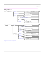
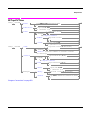
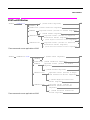
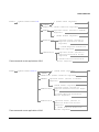
Contents
Establishing an Active GSM Link with the Mobile Station . . . . . . . . . . . . . . . . . . . . . . . . . 30
Making a Base Station Originated Call . . . . . . . . . . . . . . . . . . . . . . . . . . . . . . . . . . . . . . 30
Making a Mobile Station Originated Call . . . . . . . . . . . . . . . . . . . . . . . . . . . . . . . . . . . . 31
Operating Considerations . . . . . . . . . . . . . . . . . . . . . . . . . . . . . . . . . . . . . . . . . . . . . . . . . 31
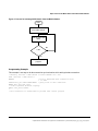
Call Processing Event Synchronization . . . . . . . . . . . . . . . . . . . . . . . . . . . . . . . . . . . . . . . . . 32
Description . . . . . . . . . . . . . . . . . . . . . . . . . . . . . . . . . . . . . . . . . . . . . . . . . . . . . . . . . . . . . 32
Call Processing Subsystem Overlapped Commands . . . . . . . . . . . . . . . . . . . . . . . . . . . . 35
Related Topics . . . . . . . . . . . . . . . . . . . . . . . . . . . . . . . . . . . . . . . . . . . . . . . . . . . . . . . . . . 36
Call Processing State Synchronization. . . . . . . . . . . . . . . . . . . . . . . . . . . . . . . . . . . . . . . . . . 37
Description . . . . . . . . . . . . . . . . . . . . . . . . . . . . . . . . . . . . . . . . . . . . . . . . . . . . . . . . . . . . . 37
Description . . . . . . . . . . . . . . . . . . . . . . . . . . . . . . . . . . . . . . . . . . . . . . . . . . . . . . . . . . . . . 37
STATus:OPERation:CALL:GSM Status Register . . . . . . . . . . . . . . . . . . . . . . . . . . . . . . 40
Call State STATus:OPERation:CALL:GSM Program Example . . . . . . . . . . . . . . . . . . . 40
Related Topics . . . . . . . . . . . . . . . . . . . . . . . . . . . . . . . . . . . . . . . . . . . . . . . . . . . . . . . . . . 41
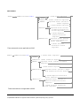
Test System Synchronization Overview. . . . . . . . . . . . . . . . . . . . . . . . . . . . . . . . . . . . . . . . . 42
Description . . . . . . . . . . . . . . . . . . . . . . . . . . . . . . . . . . . . . . . . . . . . . . . . . . . . . . . . . . . . . 42
Commands used for synchronization: . . . . . . . . . . . . . . . . . . . . . . . . . . . . . . . . . . . . . . . 44
Related Topics . . . . . . . . . . . . . . . . . . . . . . . . . . . . . . . . . . . . . . . . . . . . . . . . . . . . . . . . . . 46
Establishing a Data Connection with the Mobile Station . . . . . . . . . . . . . . . . . . . . . . . . . . . 49
Related Topics . . . . . . . . . . . . . . . . . . . . . . . . . . . . . . . . . . . . . . . . . . . . . . . . . . . . . . . . . . 49
Data Connection Processing Event Synchronization. . . . . . . . . . . . . . . . . . . . . . . . . . . . . . . 50
Description . . . . . . . . . . . . . . . . . . . . . . . . . . . . . . . . . . . . . . . . . . . . . . . . . . . . . . . . . . . . . 50
Data Connection Processing Subsystem Overlapped Commands . . . . . . . . . . . . . . . . . 52
Data Connection Processing State Synchronization . . . . . . . . . . . . . . . . . . . . . . . . . . . . . . . 53
Description . . . . . . . . . . . . . . . . . . . . . . . . . . . . . . . . . . . . . . . . . . . . . . . . . . . . . . . . . . . . . 53
Related Topics . . . . . . . . . . . . . . . . . . . . . . . . . . . . . . . . . . . . . . . . . . . . . . . . . . . . . . . . . . 54
Test System Synchronization Overview. . . . . . . . . . . . . . . . . . . . . . . . . . . . . . . . . . . . . . . . . 56
Description . . . . . . . . . . . . . . . . . . . . . . . . . . . . . . . . . . . . . . . . . . . . . . . . . . . . . . . . . . . . . 56
Commands used for synchronization: . . . . . . . . . . . . . . . . . . . . . . . . . . . . . . . . . . . . . . . 59
Related Topics . . . . . . . . . . . . . . . . . . . . . . . . . . . . . . . . . . . . . . . . . . . . . . . . . . . . . . . . . . 59
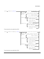
Analog Audio Measurement Description . . . . . . . . . . . . . . . . . . . . . . . . . . . . . . . . . . . . . . . . 62
How is an analog audio measurement made? . . . . . . . . . . . . . . . . . . . . . . . . . . . . . . . . . 62
Trigger Source . . . . . . . . . . . . . . . . . . . . . . . . . . . . . . . . . . . . . . . . . . . . . . . . . . . . . . . . . . 62
Related Topics . . . . . . . . . . . . . . . . . . . . . . . . . . . . . . . . . . . . . . . . . . . . . . . . . . . . . . . . . . 62
9
Contents
Programming an Analog Audio Measurement . . . . . . . . . . . . . . . . . . . . . . . . . . . . . . . . . . . 63
Programming Example . . . . . . . . . . . . . . . . . . . . . . . . . . . . . . . . . . . . . . . . . . . . . . . . . . . 63
Returned Values . . . . . . . . . . . . . . . . . . . . . . . . . . . . . . . . . . . . . . . . . . . . . . . . . . . . . . . . 63
Related Topics . . . . . . . . . . . . . . . . . . . . . . . . . . . . . . . . . . . . . . . . . . . . . . . . . . . . . . . . . . 64
AAUDio Troubleshooting . . . . . . . . . . . . . . . . . . . . . . . . . . . . . . . . . . . . . . . . . . . . . . . . . . . . 65
Possible Setup Issues . . . . . . . . . . . . . . . . . . . . . . . . . . . . . . . . . . . . . . . . . . . . . . . . . . . . 65
Interpreting Integrity Indicator values . . . . . . . . . . . . . . . . . . . . . . . . . . . . . . . . . . . . . . 65
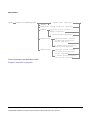
Bit Error Measurement Description . . . . . . . . . . . . . . . . . . . . . . . . . . . . . . . . . . . . . . . . . . . 66
Bit Error Measurements versus Fast Bit Error Measurements . . . . . . . . . . . . . . . . . . 66
How is a bit error (BER) measurement made? . . . . . . . . . . . . . . . . . . . . . . . . . . . . . . . . 66
BER measurement results . . . . . . . . . . . . . . . . . . . . . . . . . . . . . . . . . . . . . . . . . . . . . . . . 68
Related Topics . . . . . . . . . . . . . . . . . . . . . . . . . . . . . . . . . . . . . . . . . . . . . . . . . . . . . . . . . . 68
Programming a Bit Error Measurement . . . . . . . . . . . . . . . . . . . . . . . . . . . . . . . . . . . . . . . . 69
Programming Example . . . . . . . . . . . . . . . . . . . . . . . . . . . . . . . . . . . . . . . . . . . . . . . . . . . 70
Returned values . . . . . . . . . . . . . . . . . . . . . . . . . . . . . . . . . . . . . . . . . . . . . . . . . . . . . . . . 71
Related Topics . . . . . . . . . . . . . . . . . . . . . . . . . . . . . . . . . . . . . . . . . . . . . . . . . . . . . . . . . . 71
BERR Troubleshooting . . . . . . . . . . . . . . . . . . . . . . . . . . . . . . . . . . . . . . . . . . . . . . . . . . . . . . 72
Possible Setup Issues . . . . . . . . . . . . . . . . . . . . . . . . . . . . . . . . . . . . . . . . . . . . . . . . . . . . 72
Interpreting Integrity Indicator values . . . . . . . . . . . . . . . . . . . . . . . . . . . . . . . . . . . . . . 72
BLER Reports Measurement Description . . . . . . . . . . . . . . . . . . . . . . . . . . . . . . . . . . . . . . . 73
When are BLER Report Measurements Made? . . . . . . . . . . . . . . . . . . . . . . . . . . . . . . . 73
Programming a BLER Report Measurement . . . . . . . . . . . . . . . . . . . . . . . . . . . . . . . . . 73
Related Topics . . . . . . . . . . . . . . . . . . . . . . . . . . . . . . . . . . . . . . . . . . . . . . . . . . . . . . . . . . 75
Decoded Audio Measurement Description. . . . . . . . . . . . . . . . . . . . . . . . . . . . . . . . . . . . . . . 76
How is a decoded audio (DAUDIO) measurement made? . . . . . . . . . . . . . . . . . . . . . . . 76
Trigger Source . . . . . . . . . . . . . . . . . . . . . . . . . . . . . . . . . . . . . . . . . . . . . . . . . . . . . . . . . . 76
Related Topics . . . . . . . . . . . . . . . . . . . . . . . . . . . . . . . . . . . . . . . . . . . . . . . . . . . . . . . . . . 77
Programming a Decoded Audio Measurement . . . . . . . . . . . . . . . . . . . . . . . . . . . . . . . . . . . 78
Programming Example . . . . . . . . . . . . . . . . . . . . . . . . . . . . . . . . . . . . . . . . . . . . . . . . . . . 78
Returned Values . . . . . . . . . . . . . . . . . . . . . . . . . . . . . . . . . . . . . . . . . . . . . . . . . . . . . . . . 78
Related Topics . . . . . . . . . . . . . . . . . . . . . . . . . . . . . . . . . . . . . . . . . . . . . . . . . . . . . . . . . . 79
Decoded Audio (DAUDio) Troubleshooting . . . . . . . . . . . . . . . . . . . . . . . . . . . . . . . . . . . . . . 80
Possible Setup Issues . . . . . . . . . . . . . . . . . . . . . . . . . . . . . . . . . . . . . . . . . . . . . . . . . . . . 80
Interpreting Integrity Indicator values . . . . . . . . . . . . . . . . . . . . . . . . . . . . . . . . . . . . . . 80
10
Contents
Dynamic Power Measurement Description . . . . . . . . . . . . . . . . . . . . . . . . . . . . . . . . . . . . . . 81
How is a Dynamic Power Measurement Made? . . . . . . . . . . . . . . . . . . . . . . . . . . . . . . . 81
Single or Multi Measurements . . . . . . . . . . . . . . . . . . . . . . . . . . . . . . . . . . . . . . . . . . . . . 81
Types of Signals Dynamic Power can Measure . . . . . . . . . . . . . . . . . . . . . . . . . . . . . . . . 81
Input Signal Requirements . . . . . . . . . . . . . . . . . . . . . . . . . . . . . . . . . . . . . . . . . . . . . . . . 81
Trigger Source . . . . . . . . . . . . . . . . . . . . . . . . . . . . . . . . . . . . . . . . . . . . . . . . . . . . . . . . . . 82
Related Topics . . . . . . . . . . . . . . . . . . . . . . . . . . . . . . . . . . . . . . . . . . . . . . . . . . . . . . . . . . 82
Dynamic Power Troubleshooting . . . . . . . . . . . . . . . . . . . . . . . . . . . . . . . . . . . . . . . . . . . . . . 83
Possible Setup Issues . . . . . . . . . . . . . . . . . . . . . . . . . . . . . . . . . . . . . . . . . . . . . . . . . . . . 83
Interpreting Integrity Indicator Values . . . . . . . . . . . . . . . . . . . . . . . . . . . . . . . . . . . . . . 83
I/Q Tuning Measurement Description . . . . . . . . . . . . . . . . . . . . . . . . . . . . . . . . . . . . . . . . . . 84
How is an I/Q Tuning Measurement Made? . . . . . . . . . . . . . . . . . . . . . . . . . . . . . . . . . . 84
Single or Multi Measurements . . . . . . . . . . . . . . . . . . . . . . . . . . . . . . . . . . . . . . . . . . . . . 85
Types of Signals I/Q Tuning can Measure . . . . . . . . . . . . . . . . . . . . . . . . . . . . . . . . . . . . 85
I/Q Tuning Input Signal Requirements . . . . . . . . . . . . . . . . . . . . . . . . . . . . . . . . . . . . . . 85
Trigger Source . . . . . . . . . . . . . . . . . . . . . . . . . . . . . . . . . . . . . . . . . . . . . . . . . . . . . . . . . . 85
Related Topics . . . . . . . . . . . . . . . . . . . . . . . . . . . . . . . . . . . . . . . . . . . . . . . . . . . . . . . . . . 85
Programming an I/Q Tuning Measurement. . . . . . . . . . . . . . . . . . . . . . . . . . . . . . . . . . . . . . 86
Programming Example . . . . . . . . . . . . . . . . . . . . . . . . . . . . . . . . . . . . . . . . . . . . . . . . . . . 86
Returned Values . . . . . . . . . . . . . . . . . . . . . . . . . . . . . . . . . . . . . . . . . . . . . . . . . . . . . . . . 87
Related Topics . . . . . . . . . . . . . . . . . . . . . . . . . . . . . . . . . . . . . . . . . . . . . . . . . . . . . . . . . . 88
I/Q Tuning Troubleshooting . . . . . . . . . . . . . . . . . . . . . . . . . . . . . . . . . . . . . . . . . . . . . . . . . . 89
Possible Setup Issues . . . . . . . . . . . . . . . . . . . . . . . . . . . . . . . . . . . . . . . . . . . . . . . . . . . . 89
Interpreting Integrity Indicator Values . . . . . . . . . . . . . . . . . . . . . . . . . . . . . . . . . . . . . . 89
Fast Bit Error Measurement Description . . . . . . . . . . . . . . . . . . . . . . . . . . . . . . . . . . . . . . . 90
Bit Error Measurements vs. Fast Bit Error Measurements . . . . . . . . . . . . . . . . . . . . . . 90
How is a fast bit error (FBER) measurement made? . . . . . . . . . . . . . . . . . . . . . . . . . . . 90
FBER measurement results . . . . . . . . . . . . . . . . . . . . . . . . . . . . . . . . . . . . . . . . . . . . . . . 91
Related Topics . . . . . . . . . . . . . . . . . . . . . . . . . . . . . . . . . . . . . . . . . . . . . . . . . . . . . . . . . . 92
Programming a Fast Bit Error Measurement . . . . . . . . . . . . . . . . . . . . . . . . . . . . . . . . . . . . 93
Programming Example . . . . . . . . . . . . . . . . . . . . . . . . . . . . . . . . . . . . . . . . . . . . . . . . . . . 93
Returned values . . . . . . . . . . . . . . . . . . . . . . . . . . . . . . . . . . . . . . . . . . . . . . . . . . . . . . . . . 94
Related Topics . . . . . . . . . . . . . . . . . . . . . . . . . . . . . . . . . . . . . . . . . . . . . . . . . . . . . . . . . . 94
11
Contents
FBER Troubleshooting . . . . . . . . . . . . . . . . . . . . . . . . . . . . . . . . . . . . . . . . . . . . . . . . . . . . . . 95
Possible Setup Issues . . . . . . . . . . . . . . . . . . . . . . . . . . . . . . . . . . . . . . . . . . . . . . . . . . . . 95
Interpreting Integrity Indicator values . . . . . . . . . . . . . . . . . . . . . . . . . . . . . . . . . . . . . . 95
Output RF Spectrum Measurement Description . . . . . . . . . . . . . . . . . . . . . . . . . . . . . . . . . 96
How is an output RF spectrum (ORFS) measurement made? . . . . . . . . . . . . . . . . . . . . 96
Types of Signals ORFS can Measure . . . . . . . . . . . . . . . . . . . . . . . . . . . . . . . . . . . . . . . . 97
Input Signal Requirements . . . . . . . . . . . . . . . . . . . . . . . . . . . . . . . . . . . . . . . . . . . . . . . 98
Trigger Source . . . . . . . . . . . . . . . . . . . . . . . . . . . . . . . . . . . . . . . . . . . . . . . . . . . . . . . . . . 98
Related Topics . . . . . . . . . . . . . . . . . . . . . . . . . . . . . . . . . . . . . . . . . . . . . . . . . . . . . . . . . . 98
Programming an Output RF Spectrum Measurement . . . . . . . . . . . . . . . . . . . . . . . . . . . . . 99
Programming Example . . . . . . . . . . . . . . . . . . . . . . . . . . . . . . . . . . . . . . . . . . . . . . . . . . . 99
Returned values . . . . . . . . . . . . . . . . . . . . . . . . . . . . . . . . . . . . . . . . . . . . . . . . . . . . . . . 100
Related Topics . . . . . . . . . . . . . . . . . . . . . . . . . . . . . . . . . . . . . . . . . . . . . . . . . . . . . . . . . 100
ORFS Troubleshooting . . . . . . . . . . . . . . . . . . . . . . . . . . . . . . . . . . . . . . . . . . . . . . . . . . . . . 101
Possible Setup Issues . . . . . . . . . . . . . . . . . . . . . . . . . . . . . . . . . . . . . . . . . . . . . . . . . . . 101
Interpreting Integrity Indicator values . . . . . . . . . . . . . . . . . . . . . . . . . . . . . . . . . . . . . 102
Phase and Frequency Error Measurement Description . . . . . . . . . . . . . . . . . . . . . . . . . . . 103
How is a phase and frequency error (PFER) measurement made? . . . . . . . . . . . . . . . 103
Burst Synchronization . . . . . . . . . . . . . . . . . . . . . . . . . . . . . . . . . . . . . . . . . . . . . . . . . . 105
Related Topics . . . . . . . . . . . . . . . . . . . . . . . . . . . . . . . . . . . . . . . . . . . . . . . . . . . . . . . . . 105
Programming a Phase and Frequency Error Measurement. . . . . . . . . . . . . . . . . . . . . . . . 106
Programming Example . . . . . . . . . . . . . . . . . . . . . . . . . . . . . . . . . . . . . . . . . . . . . . . . . . 106
Returned values . . . . . . . . . . . . . . . . . . . . . . . . . . . . . . . . . . . . . . . . . . . . . . . . . . . . . . . 106
Related Topics . . . . . . . . . . . . . . . . . . . . . . . . . . . . . . . . . . . . . . . . . . . . . . . . . . . . . . . . . 107
PFER Troubleshooting . . . . . . . . . . . . . . . . . . . . . . . . . . . . . . . . . . . . . . . . . . . . . . . . . . . . . 108
Possible Setup Issues . . . . . . . . . . . . . . . . . . . . . . . . . . . . . . . . . . . . . . . . . . . . . . . . . . . 108
Interpreting Integrity Indicator values . . . . . . . . . . . . . . . . . . . . . . . . . . . . . . . . . . . . . 108
Power versus Time Measurement Description . . . . . . . . . . . . . . . . . . . . . . . . . . . . . . . . . . 109
How is a Power versus Time (PvT) measurement made? . . . . . . . . . . . . . . . . . . . . . . . 109
Types of Signals Power vs. Time Can Measure . . . . . . . . . . . . . . . . . . . . . . . . . . . . . . 110
Power vs. Time Input Signal Requirements . . . . . . . . . . . . . . . . . . . . . . . . . . . . . . . . . 111
Trigger Source . . . . . . . . . . . . . . . . . . . . . . . . . . . . . . . . . . . . . . . . . . . . . . . . . . . . . . . . . 111
Burst Synchronization . . . . . . . . . . . . . . . . . . . . . . . . . . . . . . . . . . . . . . . . . . . . . . . . . . 113
Related Topics . . . . . . . . . . . . . . . . . . . . . . . . . . . . . . . . . . . . . . . . . . . . . . . . . . . . . . . . . 113
12
Contents
Programming a Power versus Time Measurement . . . . . . . . . . . . . . . . . . . . . . . . . . . . . . . 114
Programming Example . . . . . . . . . . . . . . . . . . . . . . . . . . . . . . . . . . . . . . . . . . . . . . . . . . 114
Returned values . . . . . . . . . . . . . . . . . . . . . . . . . . . . . . . . . . . . . . . . . . . . . . . . . . . . . . . .114
Related Topics . . . . . . . . . . . . . . . . . . . . . . . . . . . . . . . . . . . . . . . . . . . . . . . . . . . . . . . . . 115
PVT Troubleshooting. . . . . . . . . . . . . . . . . . . . . . . . . . . . . . . . . . . . . . . . . . . . . . . . . . . . . . . 116
Possible Setup Issues . . . . . . . . . . . . . . . . . . . . . . . . . . . . . . . . . . . . . . . . . . . . . . . . . . . 116
Interpreting Integrity Indicator values . . . . . . . . . . . . . . . . . . . . . . . . . . . . . . . . . . . . . 117
RACH Measurement Description . . . . . . . . . . . . . . . . . . . . . . . . . . . . . . . . . . . . . . . . . . . . . 118
What is a RACH? . . . . . . . . . . . . . . . . . . . . . . . . . . . . . . . . . . . . . . . . . . . . . . . . . . . . . . . 118
Measurements that can be performed on a RACH . . . . . . . . . . . . . . . . . . . . . . . . . . . . 118
Triggering . . . . . . . . . . . . . . . . . . . . . . . . . . . . . . . . . . . . . . . . . . . . . . . . . . . . . . . . . . . . 118
Overview of Measurement Procedure in Active Cell Mode . . . . . . . . . . . . . . . . . . . . . . 118
Overview of Measurement Procedure in Test Mode . . . . . . . . . . . . . . . . . . . . . . . . . . . 119
Example Procedure . . . . . . . . . . . . . . . . . . . . . . . . . . . . . . . . . . . . . . . . . . . . . . . . . . . . . 119
Related Topics . . . . . . . . . . . . . . . . . . . . . . . . . . . . . . . . . . . . . . . . . . . . . . . . . . . . . . . . . 119
Programming a RACH Measurement . . . . . . . . . . . . . . . . . . . . . . . . . . . . . . . . . . . . . . . . . 120
Overview of Measurement Procedure . . . . . . . . . . . . . . . . . . . . . . . . . . . . . . . . . . . . . . 120
Programming Example . . . . . . . . . . . . . . . . . . . . . . . . . . . . . . . . . . . . . . . . . . . . . . . . . . 121
Related Topics . . . . . . . . . . . . . . . . . . . . . . . . . . . . . . . . . . . . . . . . . . . . . . . . . . . . . . . . . 122
RACH Troubleshooting . . . . . . . . . . . . . . . . . . . . . . . . . . . . . . . . . . . . . . . . . . . . . . . . . . . . . 123
Possible Setup Issues . . . . . . . . . . . . . . . . . . . . . . . . . . . . . . . . . . . . . . . . . . . . . . . . . . . 123
Interpreting Integrity Indicator values . . . . . . . . . . . . . . . . . . . . . . . . . . . . . . . . . . . . . 123
SACCH Report Measurement Descriptions . . . . . . . . . . . . . . . . . . . . . . . . . . . . . . . . . . . . . 124
When are SACCH Report Measurements Made? . . . . . . . . . . . . . . . . . . . . . . . . . . . . . 124
SACCH Report Measurement Results . . . . . . . . . . . . . . . . . . . . . . . . . . . . . . . . . . . . . . 125
Neighbour Report Measurement Results . . . . . . . . . . . . . . . . . . . . . . . . . . . . . . . . . . . . 126
Related Topics . . . . . . . . . . . . . . . . . . . . . . . . . . . . . . . . . . . . . . . . . . . . . . . . . . . . . . . . . 126
Transmit Power Measurement Description . . . . . . . . . . . . . . . . . . . . . . . . . . . . . . . . . . . . . 127
How is a transmit power (TXP) measurement made? . . . . . . . . . . . . . . . . . . . . . . . . . . 127
Types of Signals TX Power can Measure . . . . . . . . . . . . . . . . . . . . . . . . . . . . . . . . . . . . 127
Input Signal Requirements . . . . . . . . . . . . . . . . . . . . . . . . . . . . . . . . . . . . . . . . . . . . . . . 128
Trigger Source . . . . . . . . . . . . . . . . . . . . . . . . . . . . . . . . . . . . . . . . . . . . . . . . . . . . . . . . . 128
Related Topics . . . . . . . . . . . . . . . . . . . . . . . . . . . . . . . . . . . . . . . . . . . . . . . . . . . . . . . . . 128
13
Contents
Programming a Transmit Power Measurement . . . . . . . . . . . . . . . . . . . . . . . . . . . . . . . . . 129
Programming Example . . . . . . . . . . . . . . . . . . . . . . . . . . . . . . . . . . . . . . . . . . . . . . . . . . 129
Returned Values . . . . . . . . . . . . . . . . . . . . . . . . . . . . . . . . . . . . . . . . . . . . . . . . . . . . . . . 129
Related Topics . . . . . . . . . . . . . . . . . . . . . . . . . . . . . . . . . . . . . . . . . . . . . . . . . . . . . . . . . 129
Transmit Power Troubleshooting. . . . . . . . . . . . . . . . . . . . . . . . . . . . . . . . . . . . . . . . . . . . . 130
Possible Setup Issues . . . . . . . . . . . . . . . . . . . . . . . . . . . . . . . . . . . . . . . . . . . . . . . . . . . 130
Interpreting Integrity Indicator values . . . . . . . . . . . . . . . . . . . . . . . . . . . . . . . . . . . . . 130
Test Adherence to Standards . . . . . . . . . . . . . . . . . . . . . . . . . . . . . . . . . . . . . . . . . . . . . . . . 131
Frequency Error and Phase Error - ETSI GSM 11.10 sections 13.1 and 13.16.1 . . . . 131
TransmitterOutputPowerandBurstTimingError-ETSIGSM11.10sections13.3and13.16.2
131
Output RF Spectrum - ETSI GSM 11.10 sections 13.4 and 13.16.3 . . . . . . . . . . . . . . 132
Reference Sensitivity - ETSI GSM 11.10 section 14.2 . . . . . . . . . . . . . . . . . . . . . . . . . 133
I/Q Tuning Measurement . . . . . . . . . . . . . . . . . . . . . . . . . . . . . . . . . . . . . . . . . . . . . . . . 133
Dynamic Power Measurement . . . . . . . . . . . . . . . . . . . . . . . . . . . . . . . . . . . . . . . . . . . . 133
Burst Synchronization of Measurements . . . . . . . . . . . . . . . . . . . . . . . . . . . . . . . . . . . . . . 136
Measurement Synchronization . . . . . . . . . . . . . . . . . . . . . . . . . . . . . . . . . . . . . . . . . . . 136
Related Topics . . . . . . . . . . . . . . . . . . . . . . . . . . . . . . . . . . . . . . . . . . . . . . . . . . . . . . . . . 137
Programming a Channel Mode Change. . . . . . . . . . . . . . . . . . . . . . . . . . . . . . . . . . . . . . . . 138
Programming Example . . . . . . . . . . . . . . . . . . . . . . . . . . . . . . . . . . . . . . . . . . . . . . . . . . 138
Returned Values . . . . . . . . . . . . . . . . . . . . . . . . . . . . . . . . . . . . . . . . . . . . . . . . . . . . . . . 139
Related Topics . . . . . . . . . . . . . . . . . . . . . . . . . . . . . . . . . . . . . . . . . . . . . . . . . . . . . . . . . 139
How the Test Set Performs a Dualband Handover . . . . . . . . . . . . . . . . . . . . . . . . . . . . . . . 140
Related Topics . . . . . . . . . . . . . . . . . . . . . . . . . . . . . . . . . . . . . . . . . . . . . . . . . . . . . . . . . 140
Dealing With Semicolon Separated Response Data Lists . . . . . . . . . . . . . . . . . . . . . . . . . 141
Description . . . . . . . . . . . . . . . . . . . . . . . . . . . . . . . . . . . . . . . . . . . . . . . . . . . . . . . . . . . 141
Concurrent Measurements . . . . . . . . . . . . . . . . . . . . . . . . . . . . . . . . . . . . . . . . . . . . . . . . . . 143
Description . . . . . . . . . . . . . . . . . . . . . . . . . . . . . . . . . . . . . . . . . . . . . . . . . . . . . . . . . . . 143
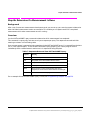
Concurrent Measurements for the GSM and GPRS Test Applications . . . . . . . . . . . . 144
Table Key . . . . . . . . . . . . . . . . . . . . . . . . . . . . . . . . . . . . . . . . . . . . . . . . . . . . . . . . . . . . 145
Related Topics . . . . . . . . . . . . . . . . . . . . . . . . . . . . . . . . . . . . . . . . . . . . . . . . . . . . . . . . . 145
14
Contents
Integrity Indicator . . . . . . . . . . . . . . . . . . . . . . . . . . . . . . . . . . . . . . . . . . . . . . . . . . . . . . . . . 146
Description . . . . . . . . . . . . . . . . . . . . . . . . . . . . . . . . . . . . . . . . . . . . . . . . . . . . . . . . . . . . 146
Programming Example . . . . . . . . . . . . . . . . . . . . . . . . . . . . . . . . . . . . . . . . . . . . . . . . . . 148
Related Topics . . . . . . . . . . . . . . . . . . . . . . . . . . . . . . . . . . . . . . . . . . . . . . . . . . . . . . . . . 148
Measurement Timeouts. . . . . . . . . . . . . . . . . . . . . . . . . . . . . . . . . . . . . . . . . . . . . . . . . . . . . 149
Description . . . . . . . . . . . . . . . . . . . . . . . . . . . . . . . . . . . . . . . . . . . . . . . . . . . . . . . . . . . . 149
Timeout Default Values . . . . . . . . . . . . . . . . . . . . . . . . . . . . . . . . . . . . . . . . . . . . . . . . . 149
Programming Example . . . . . . . . . . . . . . . . . . . . . . . . . . . . . . . . . . . . . . . . . . . . . . . . . . 150
Related Topics . . . . . . . . . . . . . . . . . . . . . . . . . . . . . . . . . . . . . . . . . . . . . . . . . . . . . . . . . 150
Invalid Measurement Results . . . . . . . . . . . . . . . . . . . . . . . . . . . . . . . . . . . . . . . . . . . . . . . . 151
Description . . . . . . . . . . . . . . . . . . . . . . . . . . . . . . . . . . . . . . . . . . . . . . . . . . . . . . . . . . . . 151
Measurement Progress Report . . . . . . . . . . . . . . . . . . . . . . . . . . . . . . . . . . . . . . . . . . . . . . . 152
Description . . . . . . . . . . . . . . . . . . . . . . . . . . . . . . . . . . . . . . . . . . . . . . . . . . . . . . . . . . . . 152
Programming Example . . . . . . . . . . . . . . . . . . . . . . . . . . . . . . . . . . . . . . . . . . . . . . . . . . 152
Related Topics . . . . . . . . . . . . . . . . . . . . . . . . . . . . . . . . . . . . . . . . . . . . . . . . . . . . . . . . . 152
Measurement Event Synchronization . . . . . . . . . . . . . . . . . . . . . . . . . . . . . . . . . . . . . . . . . 153
Description . . . . . . . . . . . . . . . . . . . . . . . . . . . . . . . . . . . . . . . . . . . . . . . . . . . . . . . . . . . . 153
INITiate:DONE? . . . . . . . . . . . . . . . . . . . . . . . . . . . . . . . . . . . . . . . . . . . . . . . . . . . . . . . 153
Programming Example . . . . . . . . . . . . . . . . . . . . . . . . . . . . . . . . . . . . . . . . . . . . . . . . . . 154
STATUS:OPERATION:NMRREADY:GSM . . . . . . . . . . . . . . . . . . . . . . . . . . . . . . . . . . 155
Operating Considerations . . . . . . . . . . . . . . . . . . . . . . . . . . . . . . . . . . . . . . . . . . . . . . . . 157
Related Topics . . . . . . . . . . . . . . . . . . . . . . . . . . . . . . . . . . . . . . . . . . . . . . . . . . . . . . . . . 157
Statistical Measurement Results . . . . . . . . . . . . . . . . . . . . . . . . . . . . . . . . . . . . . . . . . . . . . 158
Description . . . . . . . . . . . . . . . . . . . . . . . . . . . . . . . . . . . . . . . . . . . . . . . . . . . . . . . . . . . . 158
Programming Example . . . . . . . . . . . . . . . . . . . . . . . . . . . . . . . . . . . . . . . . . . . . . . . . . . 158
Related Topics . . . . . . . . . . . . . . . . . . . . . . . . . . . . . . . . . . . . . . . . . . . . . . . . . . . . . . . . . 158
Status Subsystem Overview . . . . . . . . . . . . . . . . . . . . . . . . . . . . . . . . . . . . . . . . . . . . . . . . . 159
Description . . . . . . . . . . . . . . . . . . . . . . . . . . . . . . . . . . . . . . . . . . . . . . . . . . . . . . . . . . . . 159
Related Topics . . . . . . . . . . . . . . . . . . . . . . . . . . . . . . . . . . . . . . . . . . . . . . . . . . . . . . . . . 168
Triggering of Measurements . . . . . . . . . . . . . . . . . . . . . . . . . . . . . . . . . . . . . . . . . . . . . . . . . 169
GSM and GPRS Operating Considerations . . . . . . . . . . . . . . . . . . . . . . . . . . . . . . . . . . 169
Description . . . . . . . . . . . . . . . . . . . . . . . . . . . . . . . . . . . . . . . . . . . . . . . . . . . . . . . . . . . . 169
Trigger Qualifier Description . . . . . . . . . . . . . . . . . . . . . . . . . . . . . . . . . . . . . . . . . . . . . 172
Related Topics . . . . . . . . . . . . . . . . . . . . . . . . . . . . . . . . . . . . . . . . . . . . . . . . . . . . . . . . . 172
15
Contents
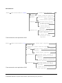
Introduction. . . . . . . . . . . . . . . . . . . . . . . . . . . . . . . . . . . . . . . . . . . . . . . . . . . . . . . . . . . . . . 176
Conventions Used in This Programming Guide . . . . . . . . . . . . . . . . . . . . . . . . . . . . . . 176
Purpose of This Programming Guide . . . . . . . . . . . . . . . . . . . . . . . . . . . . . . . . . . . . . . 176
How This Programming Guide Is Organized . . . . . . . . . . . . . . . . . . . . . . . . . . . . . . . . 176
How to Use This Programming Guide . . . . . . . . . . . . . . . . . . . . . . . . . . . . . . . . . . . . . . 178
About the Programming Examples Presented in This Programming Guide . . . . . . . 178
Step 1: Set the Test Set’s Operating Mode to Active Cell . . . . . . . . . . . . . . . . . . . . . . . . . . 179
Background . . . . . . . . . . . . . . . . . . . . . . . . . . . . . . . . . . . . . . . . . . . . . . . . . . . . . . . . . . . 179
Overview of Active Cell Operating Mode . . . . . . . . . . . . . . . . . . . . . . . . . . . . . . . . . . . 179
Setting the Test Set’s Operating Mode to Active Cell . . . . . . . . . . . . . . . . . . . . . . . . . 180
Step 2: Configure the Base Station Emulator . . . . . . . . . . . . . . . . . . . . . . . . . . . . . . . . . . . 181
Background . . . . . . . . . . . . . . . . . . . . . . . . . . . . . . . . . . . . . . . . . . . . . . . . . . . . . . . . . . . 181
Configuring the Broadcast Channel Parameters . . . . . . . . . . . . . . . . . . . . . . . . . . . . . 182
Configuring the Traffic Channel Parameters . . . . . . . . . . . . . . . . . . . . . . . . . . . . . . . . 184
Things That Can Go Wrong . . . . . . . . . . . . . . . . . . . . . . . . . . . . . . . . . . . . . . . . . . . . . . 185
Step 3: Configure the Measurement Execution Parameters . . . . . . . . . . . . . . . . . . . . . . . 186
Background . . . . . . . . . . . . . . . . . . . . . . . . . . . . . . . . . . . . . . . . . . . . . . . . . . . . . . . . . . . 186
Overview . . . . . . . . . . . . . . . . . . . . . . . . . . . . . . . . . . . . . . . . . . . . . . . . . . . . . . . . . . . . . 187
Configuring Measurement Averaging Parameters . . . . . . . . . . . . . . . . . . . . . . . . . . . . 188
Configuring Measurement Triggering Parameters . . . . . . . . . . . . . . . . . . . . . . . . . . . 189
Configuring the Burst Synchronization Parameter . . . . . . . . . . . . . . . . . . . . . . . . . . . 190
Configuring Measurement Timeout Parameters . . . . . . . . . . . . . . . . . . . . . . . . . . . . . 191
Configuring Measurement Specific Parameters . . . . . . . . . . . . . . . . . . . . . . . . . . . . . . 192
Step 4: Establish an Active Link with Mobile Station . . . . . . . . . . . . . . . . . . . . . . . . . . . . 194
Background . . . . . . . . . . . . . . . . . . . . . . . . . . . . . . . . . . . . . . . . . . . . . . . . . . . . . . . . . . . 194
Overview . . . . . . . . . . . . . . . . . . . . . . . . . . . . . . . . . . . . . . . . . . . . . . . . . . . . . . . . . . . . . 197
Process for Making a Base Station Originated Call . . . . . . . . . . . . . . . . . . . . . . . . . . . 198
Process for Making a Mobile Station Originated Call . . . . . . . . . . . . . . . . . . . . . . . . . 201
Step 5: Set the Mobile Station’s Operating Conditions. . . . . . . . . . . . . . . . . . . . . . . . . . . . 204
Overview . . . . . . . . . . . . . . . . . . . . . . . . . . . . . . . . . . . . . . . . . . . . . . . . . . . . . . . . . . . . . 204
Step 6: Make Measurements . . . . . . . . . . . . . . . . . . . . . . . . . . . . . . . . . . . . . . . . . . . . . . . . 205
Background . . . . . . . . . . . . . . . . . . . . . . . . . . . . . . . . . . . . . . . . . . . . . . . . . . . . . . . . . . . 205
Things That Can Go Wrong . . . . . . . . . . . . . . . . . . . . . . . . . . . . . . . . . . . . . . . . . . . . . . 208
Step 6a: Start Set Of Concurrent Measurements . . . . . . . . . . . . . . . . . . . . . . . . . . . . . . . . 209
Starting Measurements . . . . . . . . . . . . . . . . . . . . . . . . . . . . . . . . . . . . . . . . . . . . . . . . . 209
16
Contents
Step 6b: Determine if a Measurement Is Done . . . . . . . . . . . . . . . . . . . . . . . . . . . . . . . . . . 210
Background . . . . . . . . . . . . . . . . . . . . . . . . . . . . . . . . . . . . . . . . . . . . . . . . . . . . . . . . . . . 210
Overview . . . . . . . . . . . . . . . . . . . . . . . . . . . . . . . . . . . . . . . . . . . . . . . . . . . . . . . . . . . . . 210
Step 6c: Obtain a Set of Measurement Results . . . . . . . . . . . . . . . . . . . . . . . . . . . . . . . . . . 212
Background . . . . . . . . . . . . . . . . . . . . . . . . . . . . . . . . . . . . . . . . . . . . . . . . . . . . . . . . . . . 212
Overview . . . . . . . . . . . . . . . . . . . . . . . . . . . . . . . . . . . . . . . . . . . . . . . . . . . . . . . . . . . . . 213
Step 7: Perform an Intra-Cell Handover . . . . . . . . . . . . . . . . . . . . . . . . . . . . . . . . . . . . . . . 214
Background . . . . . . . . . . . . . . . . . . . . . . . . . . . . . . . . . . . . . . . . . . . . . . . . . . . . . . . . . . . 214
Performing an Intra-Cell Handover . . . . . . . . . . . . . . . . . . . . . . . . . . . . . . . . . . . . . . . . 214
Performing a Dual-Band Handover . . . . . . . . . . . . . . . . . . . . . . . . . . . . . . . . . . . . . . . . 215
Step 8: Disconnect the Mobile Station from the Base Station Emulator . . . . . . . . . . . . . . 218
Background . . . . . . . . . . . . . . . . . . . . . . . . . . . . . . . . . . . . . . . . . . . . . . . . . . . . . . . . . . . 218
Overview . . . . . . . . . . . . . . . . . . . . . . . . . . . . . . . . . . . . . . . . . . . . . . . . . . . . . . . . . . . . . 219
Terminating an Active Call from the Base Station Emulator . . . . . . . . . . . . . . . . . . . 219
Terminating an Active Call from the Mobile Station . . . . . . . . . . . . . . . . . . . . . . . . . . 220
Comprehensive Program Example . . . . . . . . . . . . . . . . . . . . . . . . . . . . . . . . . . . . . . . . . . . . 223
Example Program With Comments . . . . . . . . . . . . . . . . . . . . . . . . . . . . . . . . . . . . . . . . 223
Example Program Without Comments . . . . . . . . . . . . . . . . . . . . . . . . . . . . . . . . . . . . . 229
Introduction . . . . . . . . . . . . . . . . . . . . . . . . . . . . . . . . . . . . . . . . . . . . . . . . . . . . . . . . . . . . . . 236
Conventions used in this Programming Guide . . . . . . . . . . . . . . . . . . . . . . . . . . . . . . . 236
Purpose of this Programming Guide . . . . . . . . . . . . . . . . . . . . . . . . . . . . . . . . . . . . . . . 236
How this Programming Guide is Organized . . . . . . . . . . . . . . . . . . . . . . . . . . . . . . . . . 236
How to use this Programming Guide . . . . . . . . . . . . . . . . . . . . . . . . . . . . . . . . . . . . . . . 238
About the Programming Examples Presented in This Programming Guide . . . . . . . . 238
Step 1: Set the Test Set’s Operating Mode to Active Cell . . . . . . . . . . . . . . . . . . . . . . . . . . 239
Background . . . . . . . . . . . . . . . . . . . . . . . . . . . . . . . . . . . . . . . . . . . . . . . . . . . . . . . . . . . 239
Overview of Active Cell Operating Mode . . . . . . . . . . . . . . . . . . . . . . . . . . . . . . . . . . . . 239
Step 2: Configure the Base Station Emulator . . . . . . . . . . . . . . . . . . . . . . . . . . . . . . . . . . . 241
The Base Station Emulator . . . . . . . . . . . . . . . . . . . . . . . . . . . . . . . . . . . . . . . . . . . . . . 241
Configuring the Broadcast Channel Parameters . . . . . . . . . . . . . . . . . . . . . . . . . . . . . 242
Configuring the Packet Data Traffic Channel Parameters . . . . . . . . . . . . . . . . . . . . . 242
Step 3: Set the Mobile Station’s Operating Conditions . . . . . . . . . . . . . . . . . . . . . . . . . . . . 245
Mobile Station Uplink Burst Transmit Power Level . . . . . . . . . . . . . . . . . . . . . . . . . . 245
Overview . . . . . . . . . . . . . . . . . . . . . . . . . . . . . . . . . . . . . . . . . . . . . . . . . . . . . . . . . . . . . 245
17
Contents
Step 4: Configure the Measurement Execution Parameters . . . . . . . . . . . . . . . . . . . . . . . 247
Measurement Execution Parameters . . . . . . . . . . . . . . . . . . . . . . . . . . . . . . . . . . . . . . 247
Overview of the SETup subsystem . . . . . . . . . . . . . . . . . . . . . . . . . . . . . . . . . . . . . . . . 248
Configuring Measurement Averaging Parameters . . . . . . . . . . . . . . . . . . . . . . . . . . . . 248
Configuring Measurement Triggering Parameters . . . . . . . . . . . . . . . . . . . . . . . . . . . 249
Configuring the Burst Synchronization Parameter . . . . . . . . . . . . . . . . . . . . . . . . . . . 250
Configuring Measurement Timeout Parameters . . . . . . . . . . . . . . . . . . . . . . . . . . . . . 250
Configuring Measurement Specific Parameters . . . . . . . . . . . . . . . . . . . . . . . . . . . . . . 251
Step 5: Establish a Data Connection with the Mobile Station . . . . . . . . . . . . . . . . . . . . . . 253
Data Connection Status Synchronization . . . . . . . . . . . . . . . . . . . . . . . . . . . . . . . . . . . 253
Process for Establishing a Data Connection . . . . . . . . . . . . . . . . . . . . . . . . . . . . . . . . . 254
Step 6: Make Measurements . . . . . . . . . . . . . . . . . . . . . . . . . . . . . . . . . . . . . . . . . . . . . . . . 257
Measurement Concurrency . . . . . . . . . . . . . . . . . . . . . . . . . . . . . . . . . . . . . . . . . . . . . . 257
Things That Can Go Wrong . . . . . . . . . . . . . . . . . . . . . . . . . . . . . . . . . . . . . . . . . . . . . . 259
Step 6a: Start Set Of Concurrent Measurements . . . . . . . . . . . . . . . . . . . . . . . . . . . . . . . . 261
Starting Measurements . . . . . . . . . . . . . . . . . . . . . . . . . . . . . . . . . . . . . . . . . . . . . . . . . 261
Using Compound Commands to Start Multiple Measurements . . . . . . . . . . . . . . . . . 261
Step 6b: Determine if a Measurement Is Done . . . . . . . . . . . . . . . . . . . . . . . . . . . . . . . . . . 263
Background . . . . . . . . . . . . . . . . . . . . . . . . . . . . . . . . . . . . . . . . . . . . . . . . . . . . . . . . . . . 263
Overview . . . . . . . . . . . . . . . . . . . . . . . . . . . . . . . . . . . . . . . . . . . . . . . . . . . . . . . . . . . . . 263
Step 6c: Obtain a Set of Measurement Results . . . . . . . . . . . . . . . . . . . . . . . . . . . . . . . . . . 265
Background . . . . . . . . . . . . . . . . . . . . . . . . . . . . . . . . . . . . . . . . . . . . . . . . . . . . . . . . . . . 265
Overview . . . . . . . . . . . . . . . . . . . . . . . . . . . . . . . . . . . . . . . . . . . . . . . . . . . . . . . . . . . . . 266
Step 7: Reconfigure the Data Connection . . . . . . . . . . . . . . . . . . . . . . . . . . . . . . . . . . . . . . 267
Process for Reconfiguring a Data Connection . . . . . . . . . . . . . . . . . . . . . . . . . . . . . . . . 267
Step 8: Disconnect the Mobile Station from the Base Station Emulator. . . . . . . . . . . . . . 271
Data Connection Status Synchronization . . . . . . . . . . . . . . . . . . . . . . . . . . . . . . . . . . . 271
End the Data Connection . . . . . . . . . . . . . . . . . . . . . . . . . . . . . . . . . . . . . . . . . . . . . . . . 271
Initiate the GPRS detach procedure from the Mobile Station . . . . . . . . . . . . . . . . . . . 272
Comprehensive Programming Example . . . . . . . . . . . . . . . . . . . . . . . . . . . . . . . . . . . . . . . 275
Example Program . . . . . . . . . . . . . . . . . . . . . . . . . . . . . . . . . . . . . . . . . . . . . . . . . . . . . . 275
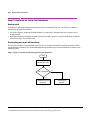
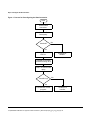
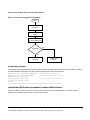
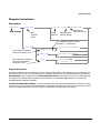
Diagram Conventions . . . . . . . . . . . . . . . . . . . . . . . . . . . . . . . . . . . . . . . . . . . . . . . . . . . . . . 283
Description . . . . . . . . . . . . . . . . . . . . . . . . . . . . . . . . . . . . . . . . . . . . . . . . . . . . . . . . . . . 283
18
Contents
ABORt Subsystem . . . . . . . . . . . . . . . . . . . . . . . . . . . . . . . . . . . . . . . . . . . . . . . . . . . . . . . . . 285
Description . . . . . . . . . . . . . . . . . . . . . . . . . . . . . . . . . . . . . . . . . . . . . . . . . . . . . . . . . . . . 285
Syntax Diagram and Command Descriptions . . . . . . . . . . . . . . . . . . . . . . . . . . . . . . . . 285
ABORt . . . . . . . . . . . . . . . . . . . . . . . . . . . . . . . . . . . . . . . . . . . . . . . . . . . . . . . . . . . . . . . . . . 286
AFGenerator Subsystem . . . . . . . . . . . . . . . . . . . . . . . . . . . . . . . . . . . . . . . . . . . . . . . . . . . . 289
Description . . . . . . . . . . . . . . . . . . . . . . . . . . . . . . . . . . . . . . . . . . . . . . . . . . . . . . . . . . . . 289
AFGenerator . . . . . . . . . . . . . . . . . . . . . . . . . . . . . . . . . . . . . . . . . . . . . . . . . . . . . . . . . . . . . 290
CALibration Subsystem . . . . . . . . . . . . . . . . . . . . . . . . . . . . . . . . . . . . . . . . . . . . . . . . . . . . 293
Description . . . . . . . . . . . . . . . . . . . . . . . . . . . . . . . . . . . . . . . . . . . . . . . . . . . . . . . . . . . . 293
Syntax Diagram and Command Descriptions . . . . . . . . . . . . . . . . . . . . . . . . . . . . . . . . 293
CALibration . . . . . . . . . . . . . . . . . . . . . . . . . . . . . . . . . . . . . . . . . . . . . . . . . . . . . . . . . . . . . . 294
CALL Subsystem . . . . . . . . . . . . . . . . . . . . . . . . . . . . . . . . . . . . . . . . . . . . . . . . . . . . . . . . . . 296
Description . . . . . . . . . . . . . . . . . . . . . . . . . . . . . . . . . . . . . . . . . . . . . . . . . . . . . . . . . . . . 296
Syntax Diagrams and Command Descriptions . . . . . . . . . . . . . . . . . . . . . . . . . . . . . . . 296
CALL:ACTivated . . . . . . . . . . . . . . . . . . . . . . . . . . . . . . . . . . . . . . . . . . . . . . . . . . . . . . . . . . 297
CALL:BA . . . . . . . . . . . . . . . . . . . . . . . . . . . . . . . . . . . . . . . . . . . . . . . . . . . . . . . . . . . . . . . . 298
CALL:BAND . . . . . . . . . . . . . . . . . . . . . . . . . . . . . . . . . . . . . . . . . . . . . . . . . . . . . . . . . . . . . 304
CALL:BCCode . . . . . . . . . . . . . . . . . . . . . . . . . . . . . . . . . . . . . . . . . . . . . . . . . . . . . . . . . . . . 305
CALL:BCHannel . . . . . . . . . . . . . . . . . . . . . . . . . . . . . . . . . . . . . . . . . . . . . . . . . . . . . . . . . . 306
CALL:BURSt . . . . . . . . . . . . . . . . . . . . . . . . . . . . . . . . . . . . . . . . . . . . . . . . . . . . . . . . . . . . . 309
CALL:CONNected . . . . . . . . . . . . . . . . . . . . . . . . . . . . . . . . . . . . . . . . . . . . . . . . . . . . . . . . .310
CALL:COUNt. . . . . . . . . . . . . . . . . . . . . . . . . . . . . . . . . . . . . . . . . . . . . . . . . . . . . . . . . . . . . 313
CALL:END . . . . . . . . . . . . . . . . . . . . . . . . . . . . . . . . . . . . . . . . . . . . . . . . . . . . . . . . . . . . . . . 317
CALL:FUNCtion . . . . . . . . . . . . . . . . . . . . . . . . . . . . . . . . . . . . . . . . . . . . . . . . . . . . . . . . . . 320
CALL:IMEI . . . . . . . . . . . . . . . . . . . . . . . . . . . . . . . . . . . . . . . . . . . . . . . . . . . . . . . . . . . . . . 323
CALL:LACode . . . . . . . . . . . . . . . . . . . . . . . . . . . . . . . . . . . . . . . . . . . . . . . . . . . . . . . . . . . . 324
CALL:MCCode . . . . . . . . . . . . . . . . . . . . . . . . . . . . . . . . . . . . . . . . . . . . . . . . . . . . . . . . . . . . 325
CALL:MNCode. . . . . . . . . . . . . . . . . . . . . . . . . . . . . . . . . . . . . . . . . . . . . . . . . . . . . . . . . . . . 326
CALL:MS . . . . . . . . . . . . . . . . . . . . . . . . . . . . . . . . . . . . . . . . . . . . . . . . . . . . . . . . . . . . . . . . 327
19
Contents
CALL:NCCode . . . . . . . . . . . . . . . . . . . . . . . . . . . . . . . . . . . . . . . . . . . . . . . . . . . . . . . . . . . . 339
CALL:OPERating . . . . . . . . . . . . . . . . . . . . . . . . . . . . . . . . . . . . . . . . . . . . . . . . . . . . . . . . . 340
CALL:ORIGinate. . . . . . . . . . . . . . . . . . . . . . . . . . . . . . . . . . . . . . . . . . . . . . . . . . . . . . . . . . 341
CALL:PAGing . . . . . . . . . . . . . . . . . . . . . . . . . . . . . . . . . . . . . . . . . . . . . . . . . . . . . . . . . . . . 342
CALL:PDTCH|PDTChannel . . . . . . . . . . . . . . . . . . . . . . . . . . . . . . . . . . . . . . . . . . . . . . . . 345
CALL:PMNCode . . . . . . . . . . . . . . . . . . . . . . . . . . . . . . . . . . . . . . . . . . . . . . . . . . . . . . . . . . 353
CALL:POWer. . . . . . . . . . . . . . . . . . . . . . . . . . . . . . . . . . . . . . . . . . . . . . . . . . . . . . . . . . . . . 355
CALL:RFGenerator. . . . . . . . . . . . . . . . . . . . . . . . . . . . . . . . . . . . . . . . . . . . . . . . . . . . . . . . 357
CALL:SIGNaling. . . . . . . . . . . . . . . . . . . . . . . . . . . . . . . . . . . . . . . . . . . . . . . . . . . . . . . . . . 364
Related Topics . . . . . . . . . . . . . . . . . . . . . . . . . . . . . . . . . . . . . . . . . . . . . . . . . . . . . . . . . 364
CALL:STATus . . . . . . . . . . . . . . . . . . . . . . . . . . . . . . . . . . . . . . . . . . . . . . . . . . . . . . . . . . . . 365
CALL:TCHannel . . . . . . . . . . . . . . . . . . . . . . . . . . . . . . . . . . . . . . . . . . . . . . . . . . . . . . . . . . 370
DISPlay Subsystem. . . . . . . . . . . . . . . . . . . . . . . . . . . . . . . . . . . . . . . . . . . . . . . . . . . . . . . . 377
Description . . . . . . . . . . . . . . . . . . . . . . . . . . . . . . . . . . . . . . . . . . . . . . . . . . . . . . . . . . . 377
Syntax Diagram and Command Descriptions . . . . . . . . . . . . . . . . . . . . . . . . . . . . . . . . 377
DISPlay . . . . . . . . . . . . . . . . . . . . . . . . . . . . . . . . . . . . . . . . . . . . . . . . . . . . . . . . . . . . . . . . . 378
FETCh? Subsystem. . . . . . . . . . . . . . . . . . . . . . . . . . . . . . . . . . . . . . . . . . . . . . . . . . . . . . . . 380
Description . . . . . . . . . . . . . . . . . . . . . . . . . . . . . . . . . . . . . . . . . . . . . . . . . . . . . . . . . . . 380
Syntax Diagrams and Command Descriptions . . . . . . . . . . . . . . . . . . . . . . . . . . . . . . . 380
FETCh:AAUDio. . . . . . . . . . . . . . . . . . . . . . . . . . . . . . . . . . . . . . . . . . . . . . . . . . . . . . . . . . . 381
FETCh:BERRor. . . . . . . . . . . . . . . . . . . . . . . . . . . . . . . . . . . . . . . . . . . . . . . . . . . . . . . . . . . 385
FETCh:DAUDio . . . . . . . . . . . . . . . . . . . . . . . . . . . . . . . . . . . . . . . . . . . . . . . . . . . . . . . . . . 393
FETCh:DPOWer . . . . . . . . . . . . . . . . . . . . . . . . . . . . . . . . . . . . . . . . . . . . . . . . . . . . . . . . . . 397
FETCh:FBERror . . . . . . . . . . . . . . . . . . . . . . . . . . . . . . . . . . . . . . . . . . . . . . . . . . . . . . . . . . 399
FETCh:IQTuning . . . . . . . . . . . . . . . . . . . . . . . . . . . . . . . . . . . . . . . . . . . . . . . . . . . . . . . . . 403
FETCh:ORFSpectrum. . . . . . . . . . . . . . . . . . . . . . . . . . . . . . . . . . . . . . . . . . . . . . . . . . . . . . 407
FETCh:PFERror . . . . . . . . . . . . . . . . . . . . . . . . . . . . . . . . . . . . . . . . . . . . . . . . . . . . . . . . . . 414
FETCh:PVTime . . . . . . . . . . . . . . . . . . . . . . . . . . . . . . . . . . . . . . . . . . . . . . . . . . . . . . . . . . . 421
FETCh:TXPower . . . . . . . . . . . . . . . . . . . . . . . . . . . . . . . . . . . . . . . . . . . . . . . . . . . . . . . . . . 433
20
Contents
INITiate Subsystem. . . . . . . . . . . . . . . . . . . . . . . . . . . . . . . . . . . . . . . . . . . . . . . . . . . . . . . . 436
Syntax Diagrams and Command Descriptions . . . . . . . . . . . . . . . . . . . . . . . . . . . . . . . 436
Description . . . . . . . . . . . . . . . . . . . . . . . . . . . . . . . . . . . . . . . . . . . . . . . . . . . . . . . . . . . . 436
INITiate Programming Examples (how INIT commands are used) . . . . . . . . . . . . . . . 436
INITiate . . . . . . . . . . . . . . . . . . . . . . . . . . . . . . . . . . . . . . . . . . . . . . . . . . . . . . . . . . . . . . . . . 438
READ? Subsystem . . . . . . . . . . . . . . . . . . . . . . . . . . . . . . . . . . . . . . . . . . . . . . . . . . . . . . . . . 442
Syntax Diagram and Command Descriptions . . . . . . . . . . . . . . . . . . . . . . . . . . . . . . . . 442
Description . . . . . . . . . . . . . . . . . . . . . . . . . . . . . . . . . . . . . . . . . . . . . . . . . . . . . . . . . . . . 442
Programming Example . . . . . . . . . . . . . . . . . . . . . . . . . . . . . . . . . . . . . . . . . . . . . . . . . . 442
READ . . . . . . . . . . . . . . . . . . . . . . . . . . . . . . . . . . . . . . . . . . . . . . . . . . . . . . . . . . . . . . . . . . . 443
RFANalyzer Subsystem . . . . . . . . . . . . . . . . . . . . . . . . . . . . . . . . . . . . . . . . . . . . . . . . . . . . 453
Description . . . . . . . . . . . . . . . . . . . . . . . . . . . . . . . . . . . . . . . . . . . . . . . . . . . . . . . . . . . . 453
RFANalyzer . . . . . . . . . . . . . . . . . . . . . . . . . . . . . . . . . . . . . . . . . . . . . . . . . . . . . . . . . . . . . . 454
SETup Subsystem . . . . . . . . . . . . . . . . . . . . . . . . . . . . . . . . . . . . . . . . . . . . . . . . . . . . . . . . . 462
Description . . . . . . . . . . . . . . . . . . . . . . . . . . . . . . . . . . . . . . . . . . . . . . . . . . . . . . . . . . . . 462
Syntax Diagrams and Command Descriptions . . . . . . . . . . . . . . . . . . . . . . . . . . . . . . . 462
SETup:AAUDio . . . . . . . . . . . . . . . . . . . . . . . . . . . . . . . . . . . . . . . . . . . . . . . . . . . . . . . . . . . 463
SETup:BERRor . . . . . . . . . . . . . . . . . . . . . . . . . . . . . . . . . . . . . . . . . . . . . . . . . . . . . . . . . . . 469
SETup:FBERror. . . . . . . . . . . . . . . . . . . . . . . . . . . . . . . . . . . . . . . . . . . . . . . . . . . . . . . . . . . 476
SETup:CONTinuous . . . . . . . . . . . . . . . . . . . . . . . . . . . . . . . . . . . . . . . . . . . . . . . . . . . . . . . 483
SETup:DAUDio . . . . . . . . . . . . . . . . . . . . . . . . . . . . . . . . . . . . . . . . . . . . . . . . . . . . . . . . . . . 484
SETup:DPOWer . . . . . . . . . . . . . . . . . . . . . . . . . . . . . . . . . . . . . . . . . . . . . . . . . . . . . . . . . . . 489
SETup:IQTuning . . . . . . . . . . . . . . . . . . . . . . . . . . . . . . . . . . . . . . . . . . . . . . . . . . . . . . . . . . 493
SETup:ORFSpectrum . . . . . . . . . . . . . . . . . . . . . . . . . . . . . . . . . . . . . . . . . . . . . . . . . . . . . . 499
SETup:PFERror. . . . . . . . . . . . . . . . . . . . . . . . . . . . . . . . . . . . . . . . . . . . . . . . . . . . . . . . . . . 508
SETup:PVTime . . . . . . . . . . . . . . . . . . . . . . . . . . . . . . . . . . . . . . . . . . . . . . . . . . . . . . . . . . . 513
SETup:TXPower . . . . . . . . . . . . . . . . . . . . . . . . . . . . . . . . . . . . . . . . . . . . . . . . . . . . . . . . . . 519
STATus Subsystem Description . . . . . . . . . . . . . . . . . . . . . . . . . . . . . . . . . . . . . . . . . . . . . . 524
Description . . . . . . . . . . . . . . . . . . . . . . . . . . . . . . . . . . . . . . . . . . . . . . . . . . . . . . . . . . . . 524
Syntax Diagrams and Command Descriptions . . . . . . . . . . . . . . . . . . . . . . . . . . . . . . . 524
21
Contents
STATus:OPERation . . . . . . . . . . . . . . . . . . . . . . . . . . . . . . . . . . . . . . . . . . . . . . . . . . . . . . . 525
Related Topics . . . . . . . . . . . . . . . . . . . . . . . . . . . . . . . . . . . . . . . . . . . . . . . . . . . . . . . . . 542
STATus:PRESet . . . . . . . . . . . . . . . . . . . . . . . . . . . . . . . . . . . . . . . . . . . . . . . . . . . . . . . . . . 543
STATus:QUEStionable . . . . . . . . . . . . . . . . . . . . . . . . . . . . . . . . . . . . . . . . . . . . . . . . . . . . . 544
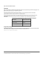
Status Byte Register . . . . . . . . . . . . . . . . . . . . . . . . . . . . . . . . . . . . . . . . . . . . . . . . . . . . . . . 559
Standard Event Status Register . . . . . . . . . . . . . . . . . . . . . . . . . . . . . . . . . . . . . . . . . . . . . 560
SYSTem Subsystem . . . . . . . . . . . . . . . . . . . . . . . . . . . . . . . . . . . . . . . . . . . . . . . . . . . . . . . 563
Description . . . . . . . . . . . . . . . . . . . . . . . . . . . . . . . . . . . . . . . . . . . . . . . . . . . . . . . . . . . 563
Syntax Diagrams and Command Descriptions . . . . . . . . . . . . . . . . . . . . . . . . . . . . . . . 563
SYSTem:APPLication . . . . . . . . . . . . . . . . . . . . . . . . . . . . . . . . . . . . . . . . . . . . . . . . . . . . . . 564
Related Topics . . . . . . . . . . . . . . . . . . . . . . . . . . . . . . . . . . . . . . . . . . . . . . . . . . . . . . . . . 568
SYSTem:BEEPer. . . . . . . . . . . . . . . . . . . . . . . . . . . . . . . . . . . . . . . . . . . . . . . . . . . . . . . . . . 569
SYSTem:COMMunicate . . . . . . . . . . . . . . . . . . . . . . . . . . . . . . . . . . . . . . . . . . . . . . . . . . . . 570
SYSTem:CONFigure . . . . . . . . . . . . . . . . . . . . . . . . . . . . . . . . . . . . . . . . . . . . . . . . . . . . . . . 574
Related Topics . . . . . . . . . . . . . . . . . . . . . . . . . . . . . . . . . . . . . . . . . . . . . . . . . . . . . . . . . 574
SYSTem:CORRection . . . . . . . . . . . . . . . . . . . . . . . . . . . . . . . . . . . . . . . . . . . . . . . . . . . . . . 575
SYSTem:CURRent:TA . . . . . . . . . . . . . . . . . . . . . . . . . . . . . . . . . . . . . . . . . . . . . . . . . . . . . 582
SYSTem:ERRor? . . . . . . . . . . . . . . . . . . . . . . . . . . . . . . . . . . . . . . . . . . . . . . . . . . . . . . . . . . 584
SYSTem:FTRigger . . . . . . . . . . . . . . . . . . . . . . . . . . . . . . . . . . . . . . . . . . . . . . . . . . . . . . . . 585
SYSTem:MEASurement . . . . . . . . . . . . . . . . . . . . . . . . . . . . . . . . . . . . . . . . . . . . . . . . . . . . 587
SYSTem:PRESet . . . . . . . . . . . . . . . . . . . . . . . . . . . . . . . . . . . . . . . . . . . . . . . . . . . . . . . . . . 588
SYSTem:ROSCillator . . . . . . . . . . . . . . . . . . . . . . . . . . . . . . . . . . . . . . . . . . . . . . . . . . . . . . 590
SYSTem:SYNChronized . . . . . . . . . . . . . . . . . . . . . . . . . . . . . . . . . . . . . . . . . . . . . . . . . . . . 591
IEEE 488.2 Common Commands . . . . . . . . . . . . . . . . . . . . . . . . . . . . . . . . . . . . . . . . . . . . . 592
Description . . . . . . . . . . . . . . . . . . . . . . . . . . . . . . . . . . . . . . . . . . . . . . . . . . . . . . . . . . . 592
Related Topics . . . . . . . . . . . . . . . . . . . . . . . . . . . . . . . . . . . . . . . . . . . . . . . . . . . . . . . . . 593
22
Contents
Frequency Banded Parameters. . . . . . . . . . . . . . . . . . . . . . . . . . . . . . . . . . . . . . . . . . . . . . . 597
GSM Frequency Banded Parameters . . . . . . . . . . . . . . . . . . . . . . . . . . . . . . . . . . . . . . . 597
GPRS Frequency Banded Parameters . . . . . . . . . . . . . . . . . . . . . . . . . . . . . . . . . . . . . . 598
Related Topics . . . . . . . . . . . . . . . . . . . . . . . . . . . . . . . . . . . . . . . . . . . . . . . . . . . . . . . . . 598
Band Selection Parameters . . . . . . . . . . . . . . . . . . . . . . . . . . . . . . . . . . . . . . . . . . . . . . . . . . 599
GSM Band Selection Parameters . . . . . . . . . . . . . . . . . . . . . . . . . . . . . . . . . . . . . . . . . . 599
GPRS Band Selection Parameters . . . . . . . . . . . . . . . . . . . . . . . . . . . . . . . . . . . . . . . . . 600
Related Topics . . . . . . . . . . . . . . . . . . . . . . . . . . . . . . . . . . . . . . . . . . . . . . . . . . . . . . . . . 601
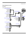
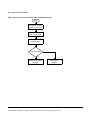
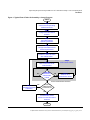
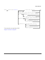
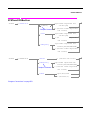
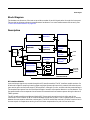
Block Diagram . . . . . . . . . . . . . . . . . . . . . . . . . . . . . . . . . . . . . . . . . . . . . . . . . . . . . . . . . . . . 602
Description . . . . . . . . . . . . . . . . . . . . . . . . . . . . . . . . . . . . . . . . . . . . . . . . . . . . . . . . . . . . 602
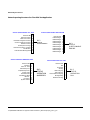
Active Cell Operating Mode . . . . . . . . . . . . . . . . . . . . . . . . . . . . . . . . . . . . . . . . . . . . . . . . . 607
Active Cell For GSM . . . . . . . . . . . . . . . . . . . . . . . . . . . . . . . . . . . . . . . . . . . . . . . . . . . . 607
Active Cell For GPRS . . . . . . . . . . . . . . . . . . . . . . . . . . . . . . . . . . . . . . . . . . . . . . . . . . . 608
Related Topics . . . . . . . . . . . . . . . . . . . . . . . . . . . . . . . . . . . . . . . . . . . . . . . . . . . . . . . . . 608
Configuring the Broadcast Channel (BCH) . . . . . . . . . . . . . . . . . . . . . . . . . . . . . . . . . . . . . 609
GSM Broadcast Channel Parameters . . . . . . . . . . . . . . . . . . . . . . . . . . . . . . . . . . . . . . 609
GPRS Broadcast Channel Parameters . . . . . . . . . . . . . . . . . . . . . . . . . . . . . . . . . . . . . . 609
Operating Considerations . . . . . . . . . . . . . . . . . . . . . . . . . . . . . . . . . . . . . . . . . . . . . . . . 610
Related Topics . . . . . . . . . . . . . . . . . . . . . . . . . . . . . . . . . . . . . . . . . . . . . . . . . . . . . . . . . 610
Setting Frame Trigger Parameters . . . . . . . . . . . . . . . . . . . . . . . . . . . . . . . . . . . . . . . . . . . 611
Frame Trigger Parameters . . . . . . . . . . . . . . . . . . . . . . . . . . . . . . . . . . . . . . . . . . . . . . . 611
Programming Examples . . . . . . . . . . . . . . . . . . . . . . . . . . . . . . . . . . . . . . . . . . . . . . . . . 611
Operating Considerations . . . . . . . . . . . . . . . . . . . . . . . . . . . . . . . . . . . . . . . . . . . . . . . . 611
Related Topics . . . . . . . . . . . . . . . . . . . . . . . . . . . . . . . . . . . . . . . . . . . . . . . . . . . . . . . . . 612
Configuring Mobile Station Operating Parameters. . . . . . . . . . . . . . . . . . . . . . . . . . . . . . . 613
GSM Mobile Station Operating Parameters . . . . . . . . . . . . . . . . . . . . . . . . . . . . . . . . . 613
GPRS Mobile Station Operating Parameters . . . . . . . . . . . . . . . . . . . . . . . . . . . . . . . . 613
Operating Considerations . . . . . . . . . . . . . . . . . . . . . . . . . . . . . . . . . . . . . . . . . . . . . . . . 613
Configuring the Packet Data Traffic Channel (PDTCH). . . . . . . . . . . . . . . . . . . . . . . . . . . 615
Packet Data Traffic Channel Parameters . . . . . . . . . . . . . . . . . . . . . . . . . . . . . . . . . . . 615
Operating Considerations . . . . . . . . . . . . . . . . . . . . . . . . . . . . . . . . . . . . . . . . . . . . . . . . 615
Related Topics . . . . . . . . . . . . . . . . . . . . . . . . . . . . . . . . . . . . . . . . . . . . . . . . . . . . . . . . . 615
23
Contents
Receiver Control . . . . . . . . . . . . . . . . . . . . . . . . . . . . . . . . . . . . . . . . . . . . . . . . . . . . . . . . . . 616
Selecting Manual or Automatic Receiver Control . . . . . . . . . . . . . . . . . . . . . . . . . . . . . 616
Operating Mode and Receiver Control . . . . . . . . . . . . . . . . . . . . . . . . . . . . . . . . . . . . . 616
Expected Power . . . . . . . . . . . . . . . . . . . . . . . . . . . . . . . . . . . . . . . . . . . . . . . . . . . . . . . . 618
Related Topics . . . . . . . . . . . . . . . . . . . . . . . . . . . . . . . . . . . . . . . . . . . . . . . . . . . . . . . . . 618
Configuring the Traffic Channel (TCH). . . . . . . . . . . . . . . . . . . . . . . . . . . . . . . . . . . . . . . . 619
TCH Parameters . . . . . . . . . . . . . . . . . . . . . . . . . . . . . . . . . . . . . . . . . . . . . . . . . . . . . . . 619
Operating Considerations . . . . . . . . . . . . . . . . . . . . . . . . . . . . . . . . . . . . . . . . . . . . . . . 619
Related Topics . . . . . . . . . . . . . . . . . . . . . . . . . . . . . . . . . . . . . . . . . . . . . . . . . . . . . . . . . 620
Test Mode Operating Mode . . . . . . . . . . . . . . . . . . . . . . . . . . . . . . . . . . . . . . . . . . . . . . . . . 621
Test Mode Operation . . . . . . . . . . . . . . . . . . . . . . . . . . . . . . . . . . . . . . . . . . . . . . . . . . . 621
Expected Burst . . . . . . . . . . . . . . . . . . . . . . . . . . . . . . . . . . . . . . . . . . . . . . . . . . . . . . . . 623
BCH Test Function Behavior . . . . . . . . . . . . . . . . . . . . . . . . . . . . . . . . . . . . . . . . . . . . . 623
BCH + TCH Test Function Behavior . . . . . . . . . . . . . . . . . . . . . . . . . . . . . . . . . . . . . . . 626
CW Test Function Behavior . . . . . . . . . . . . . . . . . . . . . . . . . . . . . . . . . . . . . . . . . . . . . . 628
Related Topics . . . . . . . . . . . . . . . . . . . . . . . . . . . . . . . . . . . . . . . . . . . . . . . . . . . . . . . . . 629
Bursted Parameters . . . . . . . . . . . . . . . . . . . . . . . . . . . . . . . . . . . . . . . . . . . . . . . . . . . . . . . 631
Operating Considerations . . . . . . . . . . . . . . . . . . . . . . . . . . . . . . . . . . . . . . . . . . . . . . . 631
Related Topics . . . . . . . . . . . . . . . . . . . . . . . . . . . . . . . . . . . . . . . . . . . . . . . . . . . . . . . . . 631
Testing a Mobile for Enhanced Full Rate Speech Channel Mode . . . . . . . . . . . . . . . . . . . 632
Related Topics . . . . . . . . . . . . . . . . . . . . . . . . . . . . . . . . . . . . . . . . . . . . . . . . . . . . . . . . . 633
Testing a GPRS Mobile Station . . . . . . . . . . . . . . . . . . . . . . . . . . . . . . . . . . . . . . . . . . . . . . 635
Test Overview . . . . . . . . . . . . . . . . . . . . . . . . . . . . . . . . . . . . . . . . . . . . . . . . . . . . . . . . . 635
Procedure . . . . . . . . . . . . . . . . . . . . . . . . . . . . . . . . . . . . . . . . . . . . . . . . . . . . . . . . . . . . 636
Operating Considerations . . . . . . . . . . . . . . . . . . . . . . . . . . . . . . . . . . . . . . . . . . . . . . . 637
Related Topics . . . . . . . . . . . . . . . . . . . . . . . . . . . . . . . . . . . . . . . . . . . . . . . . . . . . . . . . . 639
Preset Descriptions . . . . . . . . . . . . . . . . . . . . . . . . . . . . . . . . . . . . . . . . . . . . . . . . . . . . . . . . 640
Description . . . . . . . . . . . . . . . . . . . . . . . . . . . . . . . . . . . . . . . . . . . . . . . . . . . . . . . . . . . 640
Related Topics . . . . . . . . . . . . . . . . . . . . . . . . . . . . . . . . . . . . . . . . . . . . . . . . . . . . . . . . . 641
Instrument Status Area . . . . . . . . . . . . . . . . . . . . . . . . . . . . . . . . . . . . . . . . . . . . . . . . . . . . 642
Description . . . . . . . . . . . . . . . . . . . . . . . . . . . . . . . . . . . . . . . . . . . . . . . . . . . . . . . . . . . 642
How Do I Change Call Parameters? . . . . . . . . . . . . . . . . . . . . . . . . . . . . . . . . . . . . . . . . . . 644
24
Contents
How Do I Change Cell Parameters? . . . . . . . . . . . . . . . . . . . . . . . . . . . . . . . . . . . . . . . . . . . 645
A. Select the cell parameters menu. . . . . . . . . . . . . . . . . . . . . . . . . . . . . . . . . . . . . . . . . 645
B. Set a cell parameter. . . . . . . . . . . . . . . . . . . . . . . . . . . . . . . . . . . . . . . . . . . . . . . . . . . 646
How Do I Make Measurements on a Mobile?. . . . . . . . . . . . . . . . . . . . . . . . . . . . . . . . . . . . 647
A. Establish a call. . . . . . . . . . . . . . . . . . . . . . . . . . . . . . . . . . . . . . . . . . . . . . . . . . . . . . . 647
B. Select measurements. . . . . . . . . . . . . . . . . . . . . . . . . . . . . . . . . . . . . . . . . . . . . . . . . . 648
How Do I Change Measurement Setup?. . . . . . . . . . . . . . . . . . . . . . . . . . . . . . . . . . . . . . . . 649
A. Select a measurement. . . . . . . . . . . . . . . . . . . . . . . . . . . . . . . . . . . . . . . . . . . . . . . . . 649
B. Set up the measurement. . . . . . . . . . . . . . . . . . . . . . . . . . . . . . . . . . . . . . . . . . . . . . . 650
How Do I Turn Off a Measurement? . . . . . . . . . . . . . . . . . . . . . . . . . . . . . . . . . . . . . . . . . . 651
Programming Overview. . . . . . . . . . . . . . . . . . . . . . . . . . . . . . . . . . . . . . . . . . . . . . . . . . . . . 652
Related Topics . . . . . . . . . . . . . . . . . . . . . . . . . . . . . . . . . . . . . . . . . . . . . . . . . . . . . . . . . 652
Front Panel Connectors. . . . . . . . . . . . . . . . . . . . . . . . . . . . . . . . . . . . . . . . . . . . . . . . . . . . .653
Description . . . . . . . . . . . . . . . . . . . . . . . . . . . . . . . . . . . . . . . . . . . . . . . . . . . . . . . . . . . . 653
Related Topics . . . . . . . . . . . . . . . . . . . . . . . . . . . . . . . . . . . . . . . . . . . . . . . . . . . . . . . . . 654
Rear Panel Connectors . . . . . . . . . . . . . . . . . . . . . . . . . . . . . . . . . . . . . . . . . . . . . . . . . . . . .655
Description . . . . . . . . . . . . . . . . . . . . . . . . . . . . . . . . . . . . . . . . . . . . . . . . . . . . . . . . . . . . 655
Related Topics . . . . . . . . . . . . . . . . . . . . . . . . . . . . . . . . . . . . . . . . . . . . . . . . . . . . . . . . . 658
Remote/Local Mode . . . . . . . . . . . . . . . . . . . . . . . . . . . . . . . . . . . . . . . . . . . . . . . . . . . . . . . . 659
Description . . . . . . . . . . . . . . . . . . . . . . . . . . . . . . . . . . . . . . . . . . . . . . . . . . . . . . . . . . . . 659
Display Brightness . . . . . . . . . . . . . . . . . . . . . . . . . . . . . . . . . . . . . . . . . . . . . . . . . . . . . . . . 662
Description . . . . . . . . . . . . . . . . . . . . . . . . . . . . . . . . . . . . . . . . . . . . . . . . . . . . . . . . . . . . 662
Related Topics . . . . . . . . . . . . . . . . . . . . . . . . . . . . . . . . . . . . . . . . . . . . . . . . . . . . . . . . . 662
Test Set Beeper . . . . . . . . . . . . . . . . . . . . . . . . . . . . . . . . . . . . . . . . . . . . . . . . . . . . . . . . . . . 663
Description . . . . . . . . . . . . . . . . . . . . . . . . . . . . . . . . . . . . . . . . . . . . . . . . . . . . . . . . . . . . 663
Related Topics . . . . . . . . . . . . . . . . . . . . . . . . . . . . . . . . . . . . . . . . . . . . . . . . . . . . . . . . . 663
Description . . . . . . . . . . . . . . . . . . . . . . . . . . . . . . . . . . . . . . . . . . . . . . . . . . . . . . . . . . . . 664
Related Topics . . . . . . . . . . . . . . . . . . . . . . . . . . . . . . . . . . . . . . . . . . . . . . . . . . . . . . . . . 664
Obtaining Identification Information *IDN? . . . . . . . . . . . . . . . . . . . . . . . . . . . . . . . . . . . . 665
Description . . . . . . . . . . . . . . . . . . . . . . . . . . . . . . . . . . . . . . . . . . . . . . . . . . . . . . . . . . . . 665
Related Topics . . . . . . . . . . . . . . . . . . . . . . . . . . . . . . . . . . . . . . . . . . . . . . . . . . . . . . . . . 665
25
Contents
Configuring the Test Set’s LAN . . . . . . . . . . . . . . . . . . . . . . . . . . . . . . . . . . . . . . . . . . . . . . 666
Description . . . . . . . . . . . . . . . . . . . . . . . . . . . . . . . . . . . . . . . . . . . . . . . . . . . . . . . . . . . 666
Related Topics . . . . . . . . . . . . . . . . . . . . . . . . . . . . . . . . . . . . . . . . . . . . . . . . . . . . . . . . . 667
Hardware Configuration Report . . . . . . . . . . . . . . . . . . . . . . . . . . . . . . . . . . . . . . . . . . . . . 668
Description . . . . . . . . . . . . . . . . . . . . . . . . . . . . . . . . . . . . . . . . . . . . . . . . . . . . . . . . . . . 668
Related Topics . . . . . . . . . . . . . . . . . . . . . . . . . . . . . . . . . . . . . . . . . . . . . . . . . . . . . . . . . 669
Measurement Related Configuration. . . . . . . . . . . . . . . . . . . . . . . . . . . . . . . . . . . . . . . . . . 670
GSM Configuration . . . . . . . . . . . . . . . . . . . . . . . . . . . . . . . . . . . . . . . . . . . . . . . . . . . . . 670
GPRS Configuration . . . . . . . . . . . . . . . . . . . . . . . . . . . . . . . . . . . . . . . . . . . . . . . . . . . . 672
Related Topics . . . . . . . . . . . . . . . . . . . . . . . . . . . . . . . . . . . . . . . . . . . . . . . . . . . . . . . . . 675
Display Mode (Track/Fast) . . . . . . . . . . . . . . . . . . . . . . . . . . . . . . . . . . . . . . . . . . . . . . . . . . 676
Description . . . . . . . . . . . . . . . . . . . . . . . . . . . . . . . . . . . . . . . . . . . . . . . . . . . . . . . . . . . 676
Related Topics . . . . . . . . . . . . . . . . . . . . . . . . . . . . . . . . . . . . . . . . . . . . . . . . . . . . . . . . . 676
Obtaining Test Application Information . . . . . . . . . . . . . . . . . . . . . . . . . . . . . . . . . . . . . . . 677
Description . . . . . . . . . . . . . . . . . . . . . . . . . . . . . . . . . . . . . . . . . . . . . . . . . . . . . . . . . . . 677
Related Topics . . . . . . . . . . . . . . . . . . . . . . . . . . . . . . . . . . . . . . . . . . . . . . . . . . . . . . . . . 677
Timebase Description/Configuration . . . . . . . . . . . . . . . . . . . . . . . . . . . . . . . . . . . . . . . . . . 678
Description . . . . . . . . . . . . . . . . . . . . . . . . . . . . . . . . . . . . . . . . . . . . . . . . . . . . . . . . . . . 678
Related Topics . . . . . . . . . . . . . . . . . . . . . . . . . . . . . . . . . . . . . . . . . . . . . . . . . . . . . . . . . 678
Selecting a Radio Personality. . . . . . . . . . . . . . . . . . . . . . . . . . . . . . . . . . . . . . . . . . . . . . . . 679
Description . . . . . . . . . . . . . . . . . . . . . . . . . . . . . . . . . . . . . . . . . . . . . . . . . . . . . . . . . . . 679
Related Topics . . . . . . . . . . . . . . . . . . . . . . . . . . . . . . . . . . . . . . . . . . . . . . . . . . . . . . . . . 682
Error Messages . . . . . . . . . . . . . . . . . . . . . . . . . . . . . . . . . . . . . . . . . . . . . . . . . . . . . . . . . . . 684
Description . . . . . . . . . . . . . . . . . . . . . . . . . . . . . . . . . . . . . . . . . . . . . . . . . . . . . . . . . . . 685
GSM Mobile Test Maskable Messages . . . . . . . . . . . . . . . . . . . . . . . . . . . . . . . . . . . . . 686
Related Topics . . . . . . . . . . . . . . . . . . . . . . . . . . . . . . . . . . . . . . . . . . . . . . . . . . . . . . . . . 686
Fixed Timer Messages . . . . . . . . . . . . . . . . . . . . . . . . . . . . . . . . . . . . . . . . . . . . . . . . . . . . . 687
Description . . . . . . . . . . . . . . . . . . . . . . . . . . . . . . . . . . . . . . . . . . . . . . . . . . . . . . . . . . . 687
Manual User Error Messages. . . . . . . . . . . . . . . . . . . . . . . . . . . . . . . . . . . . . . . . . . . . . . . . 690
Description . . . . . . . . . . . . . . . . . . . . . . . . . . . . . . . . . . . . . . . . . . . . . . . . . . . . . . . . . . . 690
GSM and GPRS Mobile Test Manual User Messages . . . . . . . . . . . . . . . . . . . . . . . . . 691
26
Contents
-100 to -199 Command Errors. . . . . . . . . . . . . . . . . . . . . . . . . . . . . . . . . . . . . . . . . . . . . . . . 692
Description . . . . . . . . . . . . . . . . . . . . . . . . . . . . . . . . . . . . . . . . . . . . . . . . . . . . . . . . . . . . 692
Related Topics . . . . . . . . . . . . . . . . . . . . . . . . . . . . . . . . . . . . . . . . . . . . . . . . . . . . . . . . . 695
-200 to -299 Execution Errors . . . . . . . . . . . . . . . . . . . . . . . . . . . . . . . . . . . . . . . . . . . . . . . . 696
Description . . . . . . . . . . . . . . . . . . . . . . . . . . . . . . . . . . . . . . . . . . . . . . . . . . . . . . . . . . . . 696
-300 to -399 SCPI Specified Device-Specific Errors . . . . . . . . . . . . . . . . . . . . . . . . . . . . . . . 699
Description . . . . . . . . . . . . . . . . . . . . . . . . . . . . . . . . . . . . . . . . . . . . . . . . . . . . . . . . . . . . 699
Related Topics . . . . . . . . . . . . . . . . . . . . . . . . . . . . . . . . . . . . . . . . . . . . . . . . . . . . . . . . . 700
-400 to -499 Query Errors . . . . . . . . . . . . . . . . . . . . . . . . . . . . . . . . . . . . . . . . . . . . . . . . . . .701
Description . . . . . . . . . . . . . . . . . . . . . . . . . . . . . . . . . . . . . . . . . . . . . . . . . . . . . . . . . . . . 701
+100 to +199 Core Device-Specific Error . . . . . . . . . . . . . . . . . . . . . . . . . . . . . . . . . . . . . . . 702
Description . . . . . . . . . . . . . . . . . . . . . . . . . . . . . . . . . . . . . . . . . . . . . . . . . . . . . . . . . . . . 702
+200 to +299 Call Processing Device-Specific Error . . . . . . . . . . . . . . . . . . . . . . . . . . . . . . 704
+300 to +399 Link Control Device-Specific Error . . . . . . . . . . . . . . . . . . . . . . . . . . . . . . . . 707
+400 to +499 Core Hardware Device-Specific Error . . . . . . . . . . . . . . . . . . . . . . . . . . . . . . 708
Description . . . . . . . . . . . . . . . . . . . . . . . . . . . . . . . . . . . . . . . . . . . . . . . . . . . . . . . . . . . . 708
Related Topics . . . . . . . . . . . . . . . . . . . . . . . . . . . . . . . . . . . . . . . . . . . . . . . . . . . . . . . . . 710
+500 to +599 Test Application Hardware Device-Specific Error . . . . . . . . . . . . . . . . . . . . 711
Description . . . . . . . . . . . . . . . . . . . . . . . . . . . . . . . . . . . . . . . . . . . . . . . . . . . . . . . . . . . . 711
Related Topics . . . . . . . . . . . . . . . . . . . . . . . . . . . . . . . . . . . . . . . . . . . . . . . . . . . . . . . . . 711
+600 to +699 Instrument Device-Specific Error . . . . . . . . . . . . . . . . . . . . . . . . . . . . . . . . . 712
Description . . . . . . . . . . . . . . . . . . . . . . . . . . . . . . . . . . . . . . . . . . . . . . . . . . . . . . . . . . . . 712
Related Topics . . . . . . . . . . . . . . . . . . . . . . . . . . . . . . . . . . . . . . . . . . . . . . . . . . . . . . . . . 712
+700 to +799 Test Application Measurement Device-Specific Error . . . . . . . . . . . . . . . . . 713
+800 to +899 Core Measurement Device-Specific Error . . . . . . . . . . . . . . . . . . . . . . . . . . . 714
Description . . . . . . . . . . . . . . . . . . . . . . . . . . . . . . . . . . . . . . . . . . . . . . . . . . . . . . . . . . . . 714
Related Topics . . . . . . . . . . . . . . . . . . . . . . . . . . . . . . . . . . . . . . . . . . . . . . . . . . . . . . . . . 714
Error Message Log. . . . . . . . . . . . . . . . . . . . . . . . . . . . . . . . . . . . . . . . . . . . . . . . . . . . . . . . . 715
Description . . . . . . . . . . . . . . . . . . . . . . . . . . . . . . . . . . . . . . . . . . . . . . . . . . . . . . . . . . . . 715
Related Topics . . . . . . . . . . . . . . . . . . . . . . . . . . . . . . . . . . . . . . . . . . . . . . . . . . . . . . . . . 715
27
Contents
GSM Revision Information . . . . . . . . . . . . . . . . . . . . . . . . . . . . . . . . . . . . . . . . . . . . . . . . . . 716
A.05 Release May 2000 . . . . . . . . . . . . . . . . . . . . . . . . . . . . . . . . . . . . . . . . . . . . . . . . . . 716
A.04 Release - March 2000 . . . . . . . . . . . . . . . . . . . . . . . . . . . . . . . . . . . . . . . . . . . . . . . 717
A.03 Release - December 1999 . . . . . . . . . . . . . . . . . . . . . . . . . . . . . . . . . . . . . . . . . . . . 718
A.02 Release - July 1999 . . . . . . . . . . . . . . . . . . . . . . . . . . . . . . . . . . . . . . . . . . . . . . . . 719
A.01 Release - March 1999 . . . . . . . . . . . . . . . . . . . . . . . . . . . . . . . . . . . . . . . . . . . . . . . 719
A.00 Initial Release - January 1999 . . . . . . . . . . . . . . . . . . . . . . . . . . . . . . . . . . . . . . . 720
28
GSM Call Processing
1 GSM Call Processing
29
Establishing an Active GSM Link with the Mobile Station
Establishing an Active GSM Link with the Mobile Station
Making a Base Station Originated Call
The process for making a base station originated call is to:
1. If necessary, configure the traffic channel parameters for the call assignment. See “CALL:TCHannel” on
page 370.
2. If necessary, set the IMSI state. See “CALL:PAGing:IMSI” on page 342.
Example 1.
OUTPUT 714;"CALL:PAGING:IMSI ““01012345678901””"
would set the paging IMSI to 01012345678901.
3. If necessary, set the repeat paging state. See “CALL:PAGing:REPeat[:STATe]” on page 343.
Example 2.
OUTPUT 714;"CALL:PAGING:REPEAT ON"
would turn on repeat paging.
4. Configure the necessary call processing connect/disconnect synchronization conditions.
See “Call Processing State Synchronization” on page 37.
5. Page the mobile station by sending the call originate command to the test set.
Example 3.
OUTPUT 714;"CALL:ORIGINATE"
would start the process of making a base station originated call.
IMPORTANT
To verify that the origination is successfully completed, see “Call Processing State
Synchronization” on page 37.
30
Establishing an Active GSM Link with the Mobile Station
Making a Mobile Station Originated Call
The process for making a mobile station originated call is to:
1. If necessary, configure the necessary traffic channel parameters for the call assignment. See
“CALL:TCHannel” on page 370.
2. Configure the necessary call processing connect/disconnect synchronization conditions.
See “Call Processing State Synchronization” on page 37.
3. Initiate a call from the mobile station.
NOTE
There is no facility in the test set to initiate a call from the mobile station. This must be
accomplished manually or through a test bus built-in to the mobile station.
IMPORTANT
To verify that the origination is successfully completed, see “Call Processing State
Synchronization” on page 37.
Operating Considerations
The test set must be in active cell operating mode. The correct frequency band must be selected.
31
Call Processing Event Synchronization
Call Processing Event Synchronization
Description
Using the call processing subsystem overlapped command synchronization commands, you can query the test
set to find out when an overlapped command operation is done (:DONE?, :OPC?), force the test set to not
execute any more commands until an overlapped command operation has completed (:WAIT), or simply force
an overlapped command to behave as a sequential command (:SEQ).
Pending Operation Flags
Associated with each overlapped command, the test set maintains a binary indicator known as a pending
operation flag. A pending operation flag is set true when the operation started by the overlapped command is
executing, and is set false when the operation is no longer executing.
NOTE
In addition to the call processing subsystem overlapped commands, the test set also provides the
measurement-related INITiate <measurement> overlapped commands.
32
Call Processing Event Synchronization
Call Processing Subsystem Overlapped Command Synchronization Commands
Table 1. Overlapped Commands
Command
Purpose Of Command
Example
:DONE?
Returns a 0 if the associated command’s
pending operation flag is true, or a 1 if it
is false.
10
20
30
40
50
60
70
80
90
OUTPUT 714;”CALL:TCH 65”
OUTPUT 714;”SETUP:TXP:CONT OFF”
OUTPUT 714;”SETUP:PFER:CONT OFF”
REPEAT
OUTPUT 714;”CALL:TCH:DONE?”
ENTER 714;Process_done
UNTIL Process_done
OUTPUT 714;INIT:TXP;PFER”
END
The example shown is from the E1960A GSM test
application. Commands the test set to perform a
traffic channel handover and execute two setup
commands. After the two setup commands have
finished, the :DONE? command is used to find out if
the handover is finished
:SEQuential
:WAIT
Forces an overlapped command to
execute in a sequential manner. No
subsequent commands will be executed
until the pending operation flag for this
operation is false.
OUTPUT 714;”CALL:TCH:SEQ 65”
Forces the test set to wait until the
associated command’s pending
operation flag is false before executing
any more commands.
10
20
30
40
50
60
The example shown is from the E1960A GSM test
application. Commands the test set to perform a
traffic channel handover and to not execute any
more commands until the pending operation flag
associated with the CALL:TCH command is false.
OUTPUT
OUTPUT
OUTPUT
OUTPUT
OUTPUT
END
714;”CALL:TCH 65”
714;”SETUP:TXP:CONT OFF”
714;”SETUP:PFER:CONT OFF”
714;”CALL:TCH:WAIT”
714;”INIT:TXP;PFER”
The example shown is from the E1960A GSM test
application. Commands the test set to perform a
traffic channel handover and execute two setup
commands. After the two setup commands have
finished, the :WAIT command is sent to prevent the
test set from executing the INITiate command until
the handover is finished.
33
Call Processing Event Synchronization
Table 1. Overlapped Commands
Command
Purpose Of Command
Example
:OPComplete?
Places a 1 in the test set’s output queue
when the associated command’s pending
operation flag goes false. Controlling
program hangs on this query until the 1
is retrieved.
10
20
30
40
50
60
70
OUTPUT 714;”CALL:TCH 65”
OUTPUT 714;”SETUP:TXP:CONT OFF”
OUTPUT 714;”SETUP:PFER:CONT OFF”
OUTPUT 714;”CALL:TCH:OPC?”
ENTER 714;Op_complete
OUTPUT 714;”INIT:TXP;PFER”
END
The example shown is from the E1960A GSM test
application. Commands the test set to perform a
traffic channel handover and execute two setup
commands. After the two setup commands have
finished, the :OPC? command is sent to hang
program execution until a 1 is put in the test set’s
output queue, satisfying the ENTER statement and
allowing program execution to continue with the
INITiate command.
Operating Considerations
When using the call processing subsystem overlapped command synchronization commands, check the
conditions that set the operation’s pending operation flag (POF) false to avoid unexpected results.
34
S:\Hp8960\E1964A GPRS Mobile Test Application\A.00 Release\Reference_Manual\Chapters\prog_synch_callproc.fm
Call Processing Event Synchronization
Call Processing Subsystem Overlapped Commands
Call Processing Command
Purpose Of Command
Pending Operation Flag (POF) is
false when
CALL:ORIGinate
Performs a base
station call
origination.
The call processing state
leaves the Idle state (when the
operating mode is active cell),
or
See “CALL:ORIGinate” on page 341.
The test set has noted this
parameter change (when the
operating mode is test mode).
CALL:END
See “CALL:END” on page 318.
Performs a base
station call
termination.
The call processing state
reaches the Idle state (when
the operating mode is active
cell), or
The test set has noted this
parameter change (when the
operating mode is test mode).
CALL[:CELL[1]]:BCHannel[:ARFCn][:SELected]
See “CALL[:CELL]:BCHannel[:ARFCn][:SELected]” on
page 306.
CALL[:CELL[1]]:BCHannel[:ARFCn]:<broadcast band>
See “CALL:BCHannel” on page 306.
Sets the BCH
ARFCN for
currently selected
broadcast band.
The downlink signal is
transmitting on the new
broadcast channel.
Sets the BCH
ARFCN for a
broadcast band not
currently selected.
The test set has noted this
parameter change.
35
Call Processing Event Synchronization
Call Processing Command
Purpose Of Command
Pending Operation Flag (POF) is
false when
CALL:TCHannel[:ARFCn][:SELected]
Sets the TCH
ARFCN for
currently selected
traffic band.
At least one of the following
conditions has been met for all
occurrences of these call
processing commands that
have begun execution:
See “CALL:TCHannel[:ARFCn][:SELected]” on page 371.
CALL:TCHannel[:ARFCn]:<traffic band>
See “CALL:TCHannel” on page 370.
CALL:TCHannel:TSLot
See “CALL:TCHannel:TSLot” on page 376.
CALL:MS:TADVance
See “CALL:MS:TADVance” on page 335.
CALL:MS:TXLevel[:SELected]
See “CALL:MS:TXLevel[:SELected]” on page 336.
Sets the TCH
ARFCN for a traffic
band not currently
selected.
Sets the TCH
timeslot.
Sets the mobile
station timing
advance.
Sets the mobile
station transmit
level for currently
selected band.
CALL:MS:TXLevel:<traffic band>.
Sets the mobile
station transmit
level for a traffic
band not currently
selected.
CALL:CONNected:ARM[:IMMediate]
Arms the call control
status change
detector.
See “CALL:CONNected:ARM[:IMMediate]” on page 311.
Related Topics
*******************************************************
“Call Processing State Synchronization” on page 37
“Measurement Event Synchronization” on page 153
“Test System Synchronization Overview” on page 42
*******************************************************
36
S:\Hp8960\E1964A GPRS Mobile Test Application\A.00 Release\Reference_Manual\Chapters\prog_synch_callproc.fm
The channel assignment has
been successfully completed
(when a call is established), or
The test set has noted this
parameter change (no call
established), or
The test set has noted this
parameter change (not
currently selected band), or
An error message was
generated.
The call control status change
detector has been disarmed.
See “Connected/Idle Query” on
page 37.
Call Processing State Synchronization
Call Processing State Synchronization
Description
Call Processing State Query
The CALL:STATus[:STATe]? query returns a string indicating the current call processing state.
There are six possible call processing states for GSM.
The query returns one of the following strings:
• “IDLE”
Idle is returned when the test set is not on a call, involved with any termination, page, origination, or
registration call processing procedures with the mobile station.
• “SREQ”
Set Up Request is returned when the test set is in the process of assigning a channel to a mobile station as
part of a Page or a mobile station originated call setup.
• “PROC”
Proceeding is returned when the test set is in the process of connecting a call from a mobile station.
• “ALER”
Alerting is returned when the mobile station is about to receive an Alert message as part of a call setup due
to a page.
• “CONN”
Connected is returned when the test set and the mobile station are connected on a call.
• “DISC”
Disconnected is returned when the test set is in the process of ending a call.
The following command returns the current state of a data connection:
OUTPUT 714;”CALL:STATus:STATe:DATA?”
Description
Connected/Idle Query
This query will determine if a call is connected or disconnected by returning an integer value. The value
indicates if the call state is idle or connected, not if any call state change has occurred.
Query returns one of the following:
• 0 = idle
• 1 = connected
If the call is in the setup request, proceeding, alerting, or disconnecting state, this command will not return a
37
Call Processing State Synchronization
value until the call status proceeds to either connected or idle.
OUTPUT 714;”CALL:CONNECTED:STATE?”
Example 4. Using the Connected/Idle Query - Base Station Originated Call
The following example illustrates the use of the connected/idle query for a base station originated call. This
code originates a call, then waits for the connected/idle query to return a result.
Note that this code does not include the CALL:CONNECTED:TIME (timeout timer) or the
CALL:CONNECTED:ARM (change detector arm) commands. These commands are unnecessary since the
change detector is armed automatically by the CALL:ORIGINATE command, and the timeout timer value is
never applicable since a base station originated call guarantees a state change.
10
20
30
40
50
60
70
80
90
100
110
120
130
OUTPUT 714;”CALL:ORIGINATE” ! Begin the BS originated call.
OUTPUT 714;”CALL:CONNECTED:STATE?” ! The connect/idle query.
ENTER 714;Call_connected ! Program will hang here until state
! change or protocol timer expires.
!************************************************************
! If mobile is not set to auto-answer, answer the call.
!************************************************************
IF NOT Call_connected THEN
DISP “CALL NOT CONNECTED.”
ELSE
DISP “CALL IS CONNECTED.”
END IF
END
Call State Change Detector
This method provides the advantage of indicating that a call state change has occurred. The change detector
works in conjunction with the Connected /Idle Query. Arming the CALL:CONNECTED query provides a way
for the test set to know when the call state change process is done.
The call state change detector becomes disarmed when any of the following conditions have been met:
• the call processing state has progressed to either connected or idle
or...
• the attempt to connect or disconnect a call failed and one of the test set’s Fixed Timers has timed out
or...
• no call processing state changes occurred within the time period specified by the timeout timer
The following command arms the call state change detector, but does not cause any call processing function to
start:
OUTPUT 714;”CALL:CONNECTED:ARM[:IMMEDIATE]” !Used for mobile station originated calls.
These commands automatically arm the call state change detector, and start the base station originated call
processing functions:
OUTPUT 714;”CALL:ORIGINATE” !Used for base station originated call connect.
OUTPUT 714;”CALL:END” !Used for base station originated call disconnect (idle).
38
S:\Hp8960\E1964A GPRS Mobile Test Application\A.00 Release\Reference_Manual\Chapters\prog_synch_callstate.fm
Call Processing State Synchronization
Call State Change Detector Timeout
If a state change does not occur, the user needs a way to control how long to wait for the change detector. The
change detector is disarmed by the timeout timer. After a timeout, the connected/idle query will return a 1 for
connected or a 0 for idle. The timeout timer is user settable, but the user setting is only applied during mobile
station originated call processing operations. For base station originated call processing operations, the
timeout timer is automatically set to 60 seconds by the test set.
Example 5. Using the Change Detector - Mobile Station Originated Call
The following example illustrates the use of the call state change detector and connected/idle query for a
mobile station originated call. This program prompts the operator to make a call from the mobile station being
tested. When the CALL:CONNECTED:ARM command is sent, it causes the reply from the
CALL:CONNECTED:STATE? query to be held-off temporarily until the connected or idle state is reached. The
timeout is provided for cases where an expected call state change does not happen, for instance if the user does
not make the call when prompted by the program.
10
20
30
40
50
60
70
80
90
100
110
120
130
140
150
OUTPUT 714;”CALL:CONNECTED:TIMEOUT 10S” ! Sets the time out
! time to 10 seconds.
OUTPUT 714;”CALL:CONNECTED:ARM” ! Arm the change detector.
DISP “Make a mobile station orginated call. Continue when done.”
PAUSE
OUTPUT 714;”CALL:CONNECTED:STATE?” ! The connected/idle query.
ENTER 714;Call_connected
IF Call_connected=1 THEN
DISP “Call is connected.”
WAIT 2
ELSE
DISP “Call is not connected.”
WAIT 2
END IF
END
39
Call Processing State Synchronization
STATus:OPERation:CALL:GSM Status Register
The STATus subsystem provides a status register group that allows the user to query call processing states.
Call processing state synchronization can be performed using the bit transitions of
STATUS:OPERATION:CALL:GSM to generate interrupts to the external controller. Refer to
“STATus:OPERation:CALL:GSM Condition Register Bit Assignment” on page 534 for status bit definitions
and GPIB command syntax. See “Call State STATus:OPERation:CALL:GSM Program Example” on page 40.
Call State STATus:OPERation:CALL:GSM Program Example
Example 6. Generating a Service Request (SRQ) Interrupt - Dropped Call
The following example illustrates the use of the status subsystem to generate a service request when a call has
been dropped.
10
20
30
40
50
60
70
80
90
100
110
120
130
140
150
160
170
180
190
200
210
220
230
240
250
260
270
280
290
300
310
320
330
340
350
360
370
380
OUTPUT 714;”*CLS”
OUTPUT 714;”STATUS:OPERATION:CALL:ENABLE 4” !Enable the
!connected bit
! to generate a
!summary message.
OUTPUT 714;”STATUS:OPERATION:CALL:PTR 0;NTR 4” !Enable the
!negative
!transition
!filter for the
!GSM Summary bit.
OUTPUT 714;”STATUS:OPERATION:CALL:GSM:PTR 0;NTR 4” !Enable the
!negative
!transition
!filter for the
!GSM connected bit.
OUTPUT 714;”STATUS:OPERATION:CALL:GSM:ENABLE 4” !Enable the
!connected bit for
!GSM to generate a
!summary message.
OUTPUT 714;”STATUS:OPERATION:ENABLE 1024” !Enable the call sumary
!bit to generate a summary
!message.
OUTPUT 714;”*SRE 128” !Enable the service request enable register to
!generate an SRQ.
ON INTR 7,15 CALL Err !Define the interrupt-initiated branch wiht a
!priority of 15, the highest.
ENABLE INTR 7;2 !Enable interrupt on interface card 7 with a bit mask
!(for the interface’s interrupt-enable register) of 2.
PRINT “Make a call, type CONT when connected.” !Make a Mobile Station
!originated call.
PAUSE
PRINT “End the call from the mobile station and then type CONT.”
PAUSE
LOOP
OUTPUT 714;”STATUS:OPERATION:CALL:GSM:EVENT?” !Query the event register.
ENTER 714;Eve
IF Eve=0 THEN
PRINT “The call is still connected, press the end key.”
40
S:\Hp8960\E1964A GPRS Mobile Test Application\A.00 Release\Reference_Manual\Chapters\prog_synch_callstate.fm
Call Processing State Synchronization
390
400
410
420
430
440
450
460
470
END IF
END LOOP
END
SUB Err
DISP “The call has ended.”
Clear_interrupt=SPOLL(714)
OUTPUT 714;”*CLS”
STOP
SUBEND
Related Topics
*******************************************************
“Call Processing Event Synchronization” on page 32
“CALL:STATus[:STATe]?” on page 366
“CALL:CONNected:ARM[:IMMediate]” on page 311
“CALL:CONNected:TIMeout” on page 312
“Instrument Status Area” on page 642
*******************************************************
41
Test System Synchronization Overview
Test System Synchronization Overview
Description
Typical test systems include an external controller with a GPIB connection to the test set, an RF (and possible
AF) connection between the test set and a mobile station under test, and a serial connection between the
mobile station and the external controller.
Synchronizing an external controller with the test set and a mobile station under test ensures that no device
does something before it is supposed to, which can cause errors, or does something well after it could have,
which wastes time.
42
Test System Synchronization Overview
Figure 1.
Test System
GPIB
External Controller
I/O Control
Test Set
Mobile Station
RS 232
43
Test System Synchronization Overview
Sequential versus overlapped commands
The test set uses both sequential and overlapped commands:
• Sequential commands must finish executing before the next command starts to execute.
• Overlapped commands do not finish executing before the next command starts to execute.
Overlapped commands are more difficult to synchronize because an overlapped operation that started several
commands earlier may still be executing as subsequent commands are being parsed out from the input buffer
and executed. This can present a problem unless the external controller is properly synchronized to the test
set’s execution of commands. Overlapped commands allow the test set to use its internal resources as
efficiently as possible.
Methods for synchronization
The test set’s GPIB command set supports the following methods to achieve synchronization for overlapped
commands. In some cases, combinations of these methods will provide the best results:
Methods one and two do not require the external controller to query the test set, nor to perform any branching
or decision-making associated with information acquired from the test set.
Methods three through six rely on responses from the test set to an external controller, indicating that some
event has occurred. The external controller can then make decisions based on these responses to control the
flow of commands to the test set and other devices in the test system.
1. Force the test set to execute overlapped commands sequentially.
2. Force the test set to wait until an overlapped command is done executing before executing any more
commands.
3. Query the test set to determine when a command has finished executing.
4. Query the test set to determine when all commands sent to it have at least begun executing.
5. Query the test set to determine the current call or data connection processing state.
6. Program the test set to generate a service request when an operation has completed or the test set is in a
certain state.
Commands used for synchronization:
• “CALL:STATus[:STATe]?” on page 366
This command queries the test set’s current call processing state. This command supports synchronization
method five. (See “Call Processing State Query” on page 37).
• “CALL:CONNected[:STATe]?” on page 310
This command determines the connected/idle state of a call. A feature called the change detector provides
the user with a way to hold off the response to this query until a call processing state transition has taken
place. (See “Connected/Idle Query” on page 37). This command supports synchronization method five.
• :DONE? and :OPC?
44
S:\Hp8960\E1964A GPRS Mobile Test Application\A.00 Release\Reference_Manual\Chapters\prog_synch_gen.fm
Test System Synchronization Overview
These specialized commands can be appended to call processing overlapped commands to support
synchronization method three. (See “Call Processing Subsystem Overlapped Command Synchronization
Commands” on page 33.)
• :WAIT
This specialized command can be appended to call processing overlapped commands to support
synchronization method two.
(See “Call Processing Subsystem Overlapped Command Synchronization Commands” on page 33.)
• :SEQ
This specialized command can be appended to call processing overlapped commands to support
synchronization method one.
(See “Call Processing Subsystem Overlapped Command Synchronization Commands” on page 33.)
• “INITiate:DONE?” on page 439
This specialized command causes the test set to return a mnemonic indicating if a measurement is done. If
not, the returned mnemonic will indicate if the measurement is still executing. This command supports
synchronization method three.
(See “INITiate:DONE?” on page 153.)
• STATUS:<register>
Status bits in the “STATus:OPERation:CALL:GSM Condition Register Bit Assignment” on page 534
register are provided to indicate the test set’s call processing state. These bits support synchronization
methods five and six.
Status bits in the “STATus:OPERation:NMRReady:GSM Condition Register Bit Assignment” on page 540
register are provided to indicate when a measurement is ready to be fetched. These bits support
synchronization method three and six.
Many other status bits are provided in the GPIB status subsystem that are useful for synchronization.
See“STATus Subsystem Description” on page 524.
45
Test System Synchronization Overview
• “SYSTem:SYNChronized” on page 591
This specialized command causes a condition bit to be set then cleared when all prior sequential commands
have completed and all prior overlapped commands have started indicating that the input buffer is
synchronized. (See “STATus:OPERation Condition Register Bit Assignment” on page 529). This command
supports synchronization method four and six.
• “*OPC” on page 592, “*OPC?” on page 592, and “*WAI” on page 593 (not recommended)
Note: These commands look at all of the test set’s operations collectively. Because multiple processes are
likely to be executing at the same time, it is recommended that the other commands above be used instead.
Related Topics
*******************************************************
“Call Processing State Synchronization” on page 37
“Measurement Event Synchronization” on page 153
“Call Processing Event Synchronization” on page 32
“SYSTem:SYNChronized” on page 591
*******************************************************
46
S:\Hp8960\E1964A GPRS Mobile Test Application\A.00 Release\Reference_Manual\Chapters\prog_synch_gen.fm
GPRS Data Connection
2 GPRS Data Connection
47
GPRS Data Connection
48
S:\Hp8960\E1964A GPRS Mobile Test Application\A.00 Release\Reference_Manual\ch_data_connection_processing.fm
Establishing a Data Connection with the Mobile Station
Establishing a Data Connection with the Mobile Station
For step-by-step instructions on how to make a data connection, see “Step 5: Establish a Data Connection with
the Mobile Station” on page 253.
Related Topics
***********************************************************************************
“CALL:PDTCH|PDTChannel” on page 345
“CALL:FUNCtion:DATA:STARt” on page 321
“Data Connection Processing State Synchronization” on page 53
***********************************************************************************
49
Data Connection Processing Event Synchronization
Data Connection Processing Event Synchronization
Description
Using the call processing subsystem overlapped command synchronization commands, you can query the test
set to find out when an overlapped command operation is done (:DONE?, :OPC?), force the test set to not
execute any more commands until an overlapped command operation has completed (:WAIT), or simply force
an overlapped command to behave as a sequential command (:SEQ).
Pending Operation Flags
Associated with each overlapped command, the test set maintains a binary indicator known as a pending
operation flag. A pending operation flag is set true when the operation started by the overlapped command is
executing, and is set false when the operation is no longer executing.
NOTE
In addition to the call processing subsystem overlapped commands, the test set also provides the
measurement-related INITiate <measurement> overlapped commands.
50
Data Connection Processing Event Synchronization
Call Processing Subsystem Overlapped Command Synchronization Commands
Table 2. Overlapped Commands
Command
Purpose Of Command
Example
:DONE?
Returns a 0 if the associated command’s
pending operation flag is true, or a 1 if it
is false.
10
20
30
40
50
60
70
80
90
OUTPUT 714;”CALL:TCH 65”
OUTPUT 714;”SETUP:TXP:CONT OFF”
OUTPUT 714;”SETUP:PFER:CONT OFF”
REPEAT
OUTPUT 714;”CALL:TCH:DONE?”
ENTER 714;Process_done
UNTIL Process_done
OUTPUT 714;INIT:TXP;PFER”
END
The example shown is from the E1960A GSM test
application. Commands the test set to perform a
traffic channel handover and execute two setup
commands. After the two setup commands have
finished, the :DONE? command is used to find out if
the handover is finished
:SEQuential
:WAIT
Forces an overlapped command to
execute in a sequential manner. No
subsequent commands will be executed
until the pending operation flag for this
operation is false.
OUTPUT 714;”CALL:TCH:SEQ 65”
Forces the test set to wait until the
associated command’s pending
operation flag is false before executing
any more commands.
10
20
30
40
50
60
The example shown is from the E1960A GSM test
application. Commands the test set to perform a
traffic channel handover and to not execute any
more commands until the pending operation flag
associated with the CALL:TCH command is false.
OUTPUT
OUTPUT
OUTPUT
OUTPUT
OUTPUT
END
714;”CALL:TCH 65”
714;”SETUP:TXP:CONT OFF”
714;”SETUP:PFER:CONT OFF”
714;”CALL:TCH:WAIT”
714;”INIT:TXP;PFER”
The example shown is from the E1960A GSM test
application. Commands the test set to perform a
traffic channel handover and execute two setup
commands. After the two setup commands have
finished, the :WAIT command is sent to prevent the
test set from executing the INITiate command until
the handover is finished.
51
Data Connection Processing Event Synchronization
Table 2. Overlapped Commands
Command
Purpose Of Command
Example
:OPComplete?
Places a 1 in the test set’s output queue
when the associated command’s pending
operation flag goes false. Controlling
program hangs on this query until the 1
is retrieved.
10
20
30
40
50
60
70
OUTPUT 714;”CALL:TCH 65”
OUTPUT 714;”SETUP:TXP:CONT OFF”
OUTPUT 714;”SETUP:PFER:CONT OFF”
OUTPUT 714;”CALL:TCH:OPC?”
ENTER 714;Op_complete
OUTPUT 714;”INIT:TXP;PFER”
END
The example shown is from the E1960A GSM test
application. Commands the test set to perform a
traffic channel handover and execute two setup
commands. After the two setup commands have
finished, the :OPC? command is sent to hang
program execution until a 1 is put in the test set’s
output queue, satisfying the ENTER statement and
allowing program execution to continue with the
INITiate command.
Operating Considerations
When using the call processing subsystem overlapped command synchronization commands, check the
conditions that set the operation’s pending operation flag (POF) false to avoid unexpected results.
Data Connection Processing Subsystem Overlapped Commands
Data Connection Processing Command
Purpose Of Command
Pending Operation Flag (POF) is
false when
CALL:FUNCtion:DATA:STARt
Attempts to initiate a
data connection.
The connection status is any
non-transitory state other
than Attached (that is Idle, or
Transferring).
See “CALL:FUNCtion:DATA:STARt” on page 321.
Related Topics
*******************************************************
“Data Connection Processing State Synchronization” on page 53
“Measurement Event Synchronization” on page 153
“Test System Synchronization Overview” on page 56
*******************************************************
52
S:\Hp8960\E1964A GPRS Mobile Test Application\A.00 Release\Reference_Manual\Chapters\prog_synch_callprocGPRS.fm
Data Connection Processing State Synchronization
Data Connection Processing State Synchronization
Description
Data Connection Processing State Query
The CALL:STATus[:STATe]:DATA? query returns a string indicating the current data connection processing
state.
There are seven possible data connection processing states.
The query returns one of the following strings:
• “IDLE”
Idle is returned when the mobile station is not GPRS attached.
• “ATTG”
Attaching is returned when the mobile station has sent an attach request. This is a transitory state (which
means that the mobile station can only remain in this state until the protocol timer expires). At the end of
the signalling exchange, the new state will either be Attached or Idle, depending on whether or not the
attach procedure completes without error.
• “DET”
Detaching is returned when the attached mobile station has sent a detach request. This is a transitory
state (which means that the mobile station can only remain in this state until it successfully moves to
another state, or the protocol timer expires). At the end of the signalling exchange, the new state will be
Idle, even if the procedure encounters an error.
• “ATT”
Attached is returned when the mobile station has performed a successful GPRS attach.
• “STAR”
Starting is returned when you have performed the “Start Data Connection” action (using
“CALL:FUNCtion:DATA:STARt” on page 321). This is a transitory state (which means that the mobile
station can only remain in this state until it successfully moves to another state, or the protocol timer
expires). At the end of the signalling exchange, the new state will be either Transferring or Attached,
depending on whether or not the data connection is successfully established.
• “END”
Ending is returned when you have performed the “End Data Connection” action (using
“CALL:FUNCtion:DATA:STOP” on page 321). This is a transitory state (which means that the mobile
station can only remain in this state until it successfully moves to another state, or the protocol timer
expires). At the end of the signalling exchange, the new state will be Attached, even if the procedure
encounters an error.
• “TRAN”
Transferring is returned when an ETSI test mode TBF (temporary block flow) has been established.
53
Data Connection Processing State Synchronization
The following command returns the current state of a data connection:
OUTPUT 714;”CALL:STATus:STATe:DATA?”
ENTER 714;Inst_state$
Related Topics
*******************************************************
“Test System Synchronization Overview” on page 56
“Data Connection Processing Event Synchronization” on page 50
“CALL:STATus[:STATe]:DATA?” on page 366
*******************************************************
54
S:\Hp8960\E1964A GPRS Mobile Test Application\A.00 Release\Reference_Manual\Chapters\prog_synch_callstateGPRS.fm
Data Connection Processing State Synchronization
55
Test System Synchronization Overview
Test System Synchronization Overview
Description
Typical test systems include an external controller with a GPIB connection to the test set, an RF (and possible
AF) connection between the test set and a mobile station under test, and a serial connection between the
mobile station and the external controller.
Synchronizing an external controller with the test set and a mobile station under test ensures that no device
does something before it is supposed to, which can cause errors, or does something well after it could have,
which wastes time.
56
Test System Synchronization Overview
Figure 2.
Test System
GPIB
External Controller
I/O Control
Test Set
Mobile Station
RS 232
57
Test System Synchronization Overview
Sequential versus overlapped commands
The test set uses both sequential and overlapped commands:
• Sequential commands must finish executing before the next command starts to execute.
• Overlapped commands do not finish executing before the next command starts to execute.
Overlapped commands are more difficult to synchronize because an overlapped operation that started several
commands earlier may still be executing as subsequent commands are being parsed out from the input buffer
and executed. This can present a problem unless the external controller is properly synchronized to the test
set’s execution of commands. Overlapped commands allow the test set to use its internal resources as
efficiently as possible.
Methods for synchronization
The test set’s GPIB command set supports the following methods to achieve synchronization for overlapped
commands. In some cases, combinations of these methods will provide the best results:
Methods one and two do not require the external controller to query the test set, nor to perform any branching
or decision-making associated with information acquired from the test set.
Methods three through six rely on responses from the test set to an external controller, indicating that some
event has occurred. The external controller can then make decisions based on these responses to control the
flow of commands to the test set and other devices in the test system.
1. Force the test set to execute overlapped commands sequentially.
2. Force the test set to wait until an overlapped command is done executing before executing any more
commands.
3. Query the test set to determine when a command has finished executing.
4. Query the test set to determine when all commands sent to it have at least begun executing.
5. Query the test set to determine the current call or data connection processing state.
6. Program the test set to generate a service request when an operation has completed or the test set is in a
certain state.
58
S:\Hp8960\E1964A GPRS Mobile Test Application\A.00 Release\Reference_Manual\Chapters\prog_synch_genGPRS.fm
Test System Synchronization Overview
Commands used for synchronization:
• “CALL:STATus[:STATe]:DATA?” on page 366
This command queries the test set’s current GPRS data connection processing state. This command
supports synchronization method five. See “Data Connection Processing State Query” on page 53.
• :DONE? and :OPC?
These specialized commands can be appended to GPRS data connection processing overlapped commands
to support synchronization method three. See “Call Processing Subsystem Overlapped Command
Synchronization Commands” on page 51.
• :WAIT
This specialized command can be appended to GPRS data connection processing overlapped commands to
support synchronization method two.
See “Call Processing Subsystem Overlapped Command Synchronization Commands” on page 51.
• :SEQ
This specialized command can be appended to GPRS data connection processing overlapped commands to
support synchronization method one.
See “Call Processing Subsystem Overlapped Command Synchronization Commands” on page 51.
• “INITiate:DONE?” on page 439
This specialized command causes the test set to return a mnemonic indicating if a measurement is done. If
not, the returned mnemonic will indicate if the measurement is still executing. This command supports
synchronization method three.
See “INITiate:DONE?” on page 153.
• “SYSTem:SYNChronized” on page 591
This specialized command causes a condition bit to be set then cleared when all prior sequential commands
have completed and all prior overlapped commands have started indicating that the input buffer is
synchronized. (See “STATus:OPERation Condition Register Bit Assignment” on page 529). This command
supports synchronization method four and six.
• “*OPC” on page 592, “*OPC?” on page 592, and “*WAI” on page 593 (not recommended)
Note: These commands look at all of the test set’s operations collectively. Because multiple processes are
likely to be executing at the same time, it is recommended that you use the other commands above instead.
Related Topics
*******************************************************
“Data Connection Processing State Synchronization” on page 53
“Measurement Event Synchronization” on page 153
“Data Connection Processing Event Synchronization” on page 50
“SYSTem:SYNChronized” on page 591
*******************************************************
59
Test System Synchronization Overview
60
S:\Hp8960\E1964A GPRS Mobile Test Application\A.00 Release\Reference_Manual\Chapters\prog_synch_genGPRS.fm
Measurements
3 Measurements
61
Analog Audio Measurement Description
Analog Audio Measurement Description
This measurement is not applicable to GPRS.
How is an analog audio measurement made?
Analog audio measurement response is measured from the mobile station’s audio output, which also may be
an acoustic coupler or electrical connection from the mobile station connected to the test set’s AUDIO IN
connector.
The expected voltage is the absolute peak audio input signal voltage at the front panel BNC. The expected
voltage sets the analog audio clipping level and must be set. The expected voltage is peak voltage and the
results are returned as rms, so a 1-volt rms input signal would need a 1.414 Vpeak expected voltage value.
The trigger source for analog audio is always set to Immediate.
The test set has a tunable bandpass filter with a 100 Hz bandwidth that can be used to tune out ambient noise
for making 217 Hz buzz or 8 kHz whine tests. The filter’s range is from 200 Hz to 8.0 kHz.
The analog audio measurement returns the following measurement results:
• Audio Measurement Integrity Indicator
• Audio Measurement Result (0 Vrms to +20 Vrms)
• Audio Multi-measurement Maximum (0 Vrms to +20 Vrms) when multi-measurement count is on.
• Audio Multi-measurement Minimum (0 Vrms to +20 Vrms) when multi-measurement count is on.
• Audio Multi-measurement Standard Deviation (0 V to +14.14214 V) when multi-measurement count is on.
None of the analog audio measurement results are affected by amplitude offset.
When making an audio measurement on a single port you should terminate the other audio port with either a
50 ohm load or a short. This improves the accuracy of the measurement by reducing sensitivity to stray signals
at the unused port.
If noise is making your audio measurement difficult, use the 100 Hz bandwidth tunable band pass filter. This
narrow band filter reduces the noise significantly. Refer to “SETup:AAUDio:FILTer[:SFRequency]” on page
466.
Trigger Source
Analog audio measurements are triggered immediately after being armed. Arming is not necessary if the
trigger state is set to continuous.
Related Topics
*******************************************************
“Programming an Analog Audio Measurement” on page 63
“Test Adherence to Standards” on page 131
*******************************************************
62
Programming an Analog Audio Measurement
Programming an Analog Audio Measurement
This measurement is not applicable to GPRS.
This section provides an example of how to make the analog audio (AAUDio) measurement via GPIB.
The following procedure assumes that an audio source is connected to the AUDIO IN connector. See “Analog
Audio Measurement Description” on page 62.
1. Configure analog audio measurement parameters using the SETup subsystem.
2. Start the analog audio measurement using the INITiate subsystem.
3. Use the INITiate:DONE? command to find out if analog audio measurement results are available.
4. Use the FETCh? command to obtain analog audio measurement results.
Programming Example
10
20
30
40
50
60
70
80
90
100
110
120
130
140
150
160
OUTPUT 714;”SETUP:AAUDIO:CONTINUOUS OFF” !Configures the analog audio
!measurement to single trigger mode.
OUTPUT 714;”SETUP:AAUDIO:EXPECTED:VOLTAGE:PEAK 3” !Set the clipping level for
!audio input.
OUTPUT 714;”SETUP:AAUDIO:FILTER:SFREQUENCY 8KHZ” !Specifies the tunable
!bandpass filter frequency to
!be 8 kHz and turns the filter
!state ON.
OUTPUT 714;”INITIATE:AAUDIO”!Start the analog audio measurement.
REPEAT
OUTPUT 714;”INITIATE:DONE?”!Check to see if analog audio measurement is done.
ENTER 714;Meas_complete$
UNTIL Meas_complete$=”AAUD”
OUTPUT 714;”FETCH:AAUDIO?”! Fetch analog audio measurement results.
ENTER 714;Integrity, Analog_audio
END
Returned Values
The measurements returned by this program are:
• Integrity returns the measurement “Integrity Indicator” on page 146 (0 means a successful
measurement with no errors).
• Analog_audio returns the analog audio level in volts rms.
63
Programming an Analog Audio Measurement
Related Topics
*******************************************************
“Analog Audio Measurement Description” on page 62
“INITiate” on page 438
“SETup:AAUDio” on page 463
“FETCh:AAUDio” on page 381
“Comprehensive Program Example” on page 223
*******************************************************
64
S:\Hp8960\E1964A GPRS Mobile Test Application\A.00 Release\Reference_Manual\Chapters\prog_aaudio.fm
AAUDio Troubleshooting
AAUDio Troubleshooting
Possible Setup Issues
This measurement is not applicable to GPRS. To run this measurement ensure the test set is configured for
GSM measurements.
During remote operation of the analog audio measurement you should configure the trigger arm to single, see
“SETup:AAUDio:CONTinuous” on page 464.
If the trigger arm is not set to single, the measurement may not return a result. When trigger arm is
continuous the measurement rearms itself and starts another measurement cycle, during remote operation
the fetch query may not be synchronized to the measurement cycle, see “Measurement States” on page 170.
The analog audio measurement results are rms values, the Expected Peak Audio Amplitude is a peak value.
Interpreting Integrity Indicator values
See “Integrity Indicator” on page 146.
If over range (5) is returned then the input level is greater than 3dB above the Expected Peak Audio
Amplitude value or the maximum input level of 20 volts peak.
If under range (6) is returned then the input level is greater than 20dB below the Expected Peak Audio
Amplitude value maximum value.
If the signal has both over range and under range conditions only the over range (5) will be indicated.
65
Bit Error Measurement Description
Bit Error Measurement Description
This measurement is not applicable to GPRS.
Bit Error Measurements versus Fast Bit Error Measurements
There are three commonly used types of bit error measurements in GSM:
• ‘‘BER with Frame Erasure” or ‘‘Residual BER” when the mobile station has been configured to loopback
Type A.
• ‘‘BER without Frame Erasure” or ‘‘Non-residual BER” when the mobile station has been configured to
loopback Type B.
•
BER using burst-by-burst loopback when the mobile station has been configured to loopback Type C.
The test set allows you to select between Loopback Type A or B, and the fast bit error measurement, which
uses Loopback Type C. Refer also to “Fast Bit Error Measurement Description” on page 90.
NOTE
If the test set has codeware version A.02.00 or above, unnecessary loopback commands and
delays can be eliminated by taking advantage of enhancements available.
Previous versions of the test set required you to set the loopback type, and did not have a feature
that allowed time for the loop to close.
How is a bit error (BER) measurement made?
During BER measurements, the test set generates a downlink TCH with pseudo-random binary sequence,
PRBS-15, data at a known level. The mobile station receives the data, loops it back to its transmitter, and
returns the data to the test set. The test set compares data sent to data received, and BER is calculated.
SETup subsystem commands are sent to the test set to specify the time taken to close it’s loopback path,
whether to open or close a loop during downlink signaling operations (for example, channel assignment), the
number of bits to test, measurement type, speech frames delay, measurements units, trigger arm, and
measurement timeout values.
When a call is established on the TCH, the loopback type corresponding to one of the BER measurement types
must be sent to the mobile station. The test set closes the loopback automatically and re-opens it when the
measurement is closed (that is, when INITiate:BERRor is OFF).
You must set the measurement type from one of the six measurement types available, (see
“SETup:BERRor[:TYPE]” on page 471). If you query a residual result when a non-residual measurement is
initiated, the test set returns 9.91 E+37 (NAN). Measurement type must be set before initiating a BER
measurement. See “Measurements type” on page 67
The loop must be closed before a BER test can start, using the close loop signalling delay time feature allows
time for the loop to close. See “SETup:BERRor:CLSDelay[:STIMe]” on page 470 for more details.
Each mobile station may have a different time delay between receiving a speech frame and re-sending it on the
uplink. By default, the test set is configured to LDControl:AUTO:ON, and the amount of delay needed is
determined automatically when the test set has, for two frames, correctly received 80% of the downlink bits
back on the uplink. The test set can be queried for the speech frames delay value.
66
Bit Error Measurement Description
If necessary, you can manually set the delay (see “SETup:BERRor:LDControl:AUTO” on page 473).
NOTE
In case the test set is not able to correlate the data it transmits on the downlink with the data it
receives on the uplink, a Measurement Timeout value should be set. If a timeout is not set and
the test set is unable to correlate, the measurement will appear to “hang”.
The BER measurement trigger source is always set to immediate. The BER measurement does not offer
multi-measurement results. See “Statistical Measurement Results” on page 158
BER, FBER, and DAUDIO (uplink speech level) measurements are mutually exclusive measurements.
Whichever of these measurements is activated last forces the others to stop.
Measurements type
Residual:
• Residual Type IA (50 bits per speech frame)
• Residual Type IB (132 bits per speech frame)
• Residual Type II (78 bits per speech frame)
Loopback Type A is sent to the mobile station when one of these residual measurement types is selected. A
BER measurement with FE will return the frame erasure count or ratio results. The mobile station will
indicate in the speech frame, if the downlink frame was received with CRC (cyclic redundancy check) errors
the speech frames are erased. The mobile station sets all bits in the uplink speech frame to 0, indicating
speech frames were erased.
Non-residual:
• Type IA (50 bits per speech frame)
• Type IB (132 bits per speech frame)
• Type II (78 bits per speech frame)
Loopback Type B is sent to the mobile station when one of these non-residual measurement types is selected.
A BER measurement with CRC’s (cyclic redundancy check) will return the CRC count or ratio results. The
mobile station will not indicate if any speech frames in the downlink were erased.
67
Bit Error Measurement Description
BER measurement results
The results of a BER measurement can be displayed in two ways, (number of errors counted) or (the ratio bad
bits (errors) to total bits counted). If you are using the test set manually, select either Count or % from the
Measurement Units field. If you are using the test set remotely, these results are available using the FETCh
command, see “FETCh:BERRor:COUNt[:BITS]?” on page 388 or “FETCh:BERRor:RATio[:BITS]?” on page
391. Alternatively the “FETCh:BERRor[:ALL]?” on page 387 or “FETCh:BERRor:FULL?” on page 390 can also
be used to return the results.
Type A Residual Measurement Results
•
Integrity Indicator
•
Bit Error Ratio
•
•
•
Bits Tested
Bit Error Count
Frame Erasure Ratio
•
Frame Erasure Count
Type B Non-Residual Measurement Results
•
Integrity Indicator
•
Bit Error Ratio
•
•
•
•
Bits Tested
Bit Error Count
CRC Ratio
CRC Count
Related Topics
*******************************************************
“Programming a Bit Error Measurement” on page 69
“Test Adherence to Standards” on page 131
“Fast Bit Error Measurement Description” on page 90
“Programming a Fast Bit Error Measurement” on page 93
“CALL:TCHannel:LOOPback” on page 375
“BERR Troubleshooting” on page 72
*******************************************************
68
S:\Hp8960\E1964A GPRS Mobile Test Application\A.00 Release\Reference_Manual\Chapters\meas_ber_desc.fm
Programming a Bit Error Measurement
Programming a Bit Error Measurement
This measurement is not applicable to GPRS.
This section provides an example of how to make the bit error (BER) measurement via GPIB.
The following procedure assumes that an active link is established between the test set and the mobile station.
See “Establishing an Active GSM Link with the Mobile Station” on page 30.
1. Set the cell power to a good level.
2. Configure BER measurement parameters using the SETup subsystem.
3. Set the measurement type (either residual Type IA, Type IB, Type II, or non-residual Type IA, Type IB,
Type II).
4. Set the cell power to a low level for BER measurement.
5. Use the INITiate command to begin a BER measurement.
6. Use the INITiate:DONE? command to find out if the BER measurement results are available.
7. Use the FETCh? command to obtain BER measurement results.
8. Set the cell power to a good level.
69
Programming a Bit Error Measurement
Programming Example
10
20
30
40
50
60
70
80
90
100
110
120
130
140
150
160
170
180
190
200
210
220
230
240
250
260
270
280
290
300
OUTPUT 714;”SETUP:BERROR:TIMEOUT:TIME 5” ! BER measurement times out after
! 5 seconds.
OUTPUT 714;”CALL:CELL:POWER:AMPLITUDE -102 DBM” ! Sets the cell power level
! to a “low” level for the
! BER measurement.
OUTPUT 714;”SETUP:BERROR:CONTINUOUS OFF” ! Configures a BER measurement to
! Single Trigger.
OUTPUT 714;”SETUP:BERROR:COUNT 10000” ! Sets the number of bits to measure
! at 10,000.
OUTPUT 714;”SETUP:BERROR:CLSDELAY:STIME 500 MS” ! Sets the Close Loop Delay
! to 500 ms.
OUTPUT 714;”SETUP:BERROR:SLCONTROL ON” ! Sets the Signal Loop Control state to on.
OUTPUT 714;”SETUP:BERROR:TYPE TYPEIA” ! Sets the Measurement Type to IA.
OUTPUT 714;”SETUP:BERROR:LDCONTROL:AUTO OFF” ! Configure loopback delay
! control to manual.
OUTPUT 714;”SETUP:BERROR:MANUAL:DELAY 6” ! Set frame delay to 6 frames in order
! to correlate uplink and downlink bits.
OUTPUT 714;”INITIATE:BERROR” ! Start a BER measurement.
REPEAT
OUTPUT 714;”INITIATE:DONE?”
ENTER 714;Meas_comp$
PRINT Meas_comp$
UNTIL Meas_comp$=”BERR”
OUTPUT 714;”FETCH:BERROR?” ! BERR results.
ENTER 714;Integrity,Bits_tested,Bit_err_ratio,Bit_err_count
OUTPUT 714;”FETCH:BERROR:COUNT:CRC?” ! Query CRC Count results.
ENTER 714;Crc_count
OUTPUT 714;”CALL:CELL:POWER:AMPLITUDE -85 DBM” ! Sets the cell power level
! to a good level.
END
Alternatively, you could use the “FETCh:BERRor:FULL?” query to return the same results but for all bit types
simultaneously.
70
S:\Hp8960\E1964A GPRS Mobile Test Application\A.00 Release\Reference_Manual\Chapters\prog_berr_proc.fm
Programming a Bit Error Measurement
Returned values
The measurements returned by this program are:
• Integrity Indicator returns the “Integrity Indicator” on page 146 (0 means a successful measurement with
no errors).
• Bits_tested returns the number of bits tested.
• Bit_err_ratio returns the ratio of bit errors to total bits tested.
• Bit_err_count returns the number of bit errors.
• Crc_count returns the CRC count (cyclic redundancy check).
Related Topics
*******************************************************
“Bit Error Measurement Description” on page 66
“SETup:BERRor” on page 469
“INITiate” on page 438
“FETCh:BERRor” on page 385
“Comprehensive Program Example” on page 223
“BERR Troubleshooting” on page 72
*******************************************************
71
BERR Troubleshooting
BERR Troubleshooting
Possible Setup Issues
This measurement is not applicable to GPRS. To run this measurement ensure the test set is configured for
GSM measurements.
During remote operation of the bit error measurement you should configure the trigger arm to single, see
“SETup:BERRor:CONTinuous” on page 472.
If the trigger arm is not set to single, the measurement may not return a result. When trigger arm is
continuous the measurement rearms itself and starts another measurement cycle, during remote operation
the fetch query may not be synchronized to the measurement cycle, see
“Measurement States” on page 170.
If you have a BER measurement active and your mobile drops the call it may be that you have the
“SETup:BERRor:SLControl” on page 474 command set to OFF. This is likely to occur with mobiles that do not
respond to downlink signalling when loopback is closed. To solve this problem set the command to ON.
Interpreting Integrity Indicator values
See “Integrity Indicator” on page 146.
72
BLER Reports Measurement Description
BLER Reports Measurement Description
This measurement is not applicable to GSM.
Block Error Rate (BLER) reports can be used in the production process to test the performance of a GPRS
mobile station’s receiver. The BLER result is derived from the Radio Link Control (RLC) layer’s Packet
ACK/NACK (Acknowledged/Not Acknowledged) message. BLER is simply the ratio of the number of
negatively acknowledged packets to the total number of packets acknowledged by the mobile station.
The test set uses an Agilent proprietary data connection to enable BLER reports to be retrieved from the
mobile station (see “CALL:FUNCtion:DATA:TYPE” on page 321).
When are BLER Report Measurements Made?
You obtain BLER results using the GPIB query “CALL:STATus:PDTCH | PDTChannel:BLERror?” on page
367. This query returns the percentage of blocks tested that were in error and the total number of blocks used
to generate the BLER result. The BLER results are reset using “SYSTem:MEASurement:RESet” on page 587.
The BLER results are only available when the data connection status is transferring (TRAN). If you require
details on data connection states, see “Data Connection Processing State Synchronization” on page 53.
Programming a BLER Report Measurement
This section provides an example of how to use BLER reports to test your mobile station’s receiver via GPIB.
The following procedure assumes that a data connection has been established between the test set and the
mobile station (connection status is Transferring). See “Step 5: Establish a Data Connection with the Mobile
Station” on page 253.
1. Use the CALL:STATus:PDTCH:BLERror? query to obtain the first BLER results.
2. End the data connection and then re-configure the downlink PDTCH power levels using the CALL:
subsystem.
3. Reset the BLER results and then re-start the data connection.
4. Use the CALL:STATus:PDTCH:BLERror? query to obtain the second BLER results.
73
BLER Reports Measurement Description
Programming Example
10
20
30
40
50
60
70
80
90
100
110
120
130
140
150
160
170
180
190
200
210
220
230
240
250
260
270
280
290
300
310
320
330
340
350
360
370
380
390
400
410
420
430
440
450
460
470
480
! This code assumes that the current data connection state is Transferring
!
!
! Read the initial BLER result
OUTPUT 714;"CALL:STAT:PDTCH:BLER?"
ENTER 714;Bler_initial,Blocks_initial
!
! Print results at initial downlink PDTCH power level
! of -90 dBm(-60 dBm BCH level - 30 dB fixed P0 level)
PRINT "BLER Result at downlink PDTCH power of -90 dBm = ";Bler_initial
PRINT "Blocks tested at -90 dBm = ";Blocks_initial
!
!
! End the data connection before changing the downlink PDTCH power level
OUTPUT 714;"CALL:FUNC:DATA:STOP"
! Check the connection status to make sure the state is Attached
WAIT 4
OUTPUT 714;"CALL:STAT:DATA?"
ENTER 714;Conn_stat$
IF Conn_stat$<>"ATT" THEN
PRINT "Data Connection was not stopped"
STOP
END IF
!
! Set up and select the downlink PDTCH power reduction levels for bursts 1 and 2
OUTPUT 714;"CALL:PDTCH:PRED:LEV1 10db"
OUTPUT 714;"CALL:PDTCH:PRED:BURS1 PRL1"
OUTPUT 714;"CALL:PDTCH:PRED:BURS2 PRL1"
OUTPUT 714;”SYST:MEAS:RES” ! Reset the BLER results
! Now re-establish the data connection
OUTPUT 714;"CALL:FUNC:DATA:STAR:SEQ"
! Check the connection status to make sure the state is Transferring
WAIT 4
OUTPUT 714;"CALL:STAT:DATA?"
ENTER 714;Conn_stat$
IF Conn_state$<>"TRAN" THEN
PRINT "Data connection failed. Terminated program."
STOP
END IF
!
! Now obtain the second set of BLER results at lower downlink PDTCH power level
OUTPUT 714;"CALL:STAT:PDTCH:BLER?"
ENTER 714;Bler_second,Blocks_second
!
! Print results at lower downlink PDTCH power level of -100 dBm
PRINT "BLER Result at downlink PDTCH power of -100 dBm = ";Bler_second
PRINT "Blocks tested at -100 dBm = ";Blocks_second
END
74
S:\Hp8960\E1964A GPRS Mobile Test Application\A.00 Release\Reference_Manual\Chapters\meas_bler_rep_desc.fm
BLER Reports Measurement Description
Returned Values
The measurement reports returned by this program are:
• Bler_initial returns the BLER result, in percent (%) when the downlink PDTCH power levels are at
their default value of -90 dBm.
• Blocks_initial returns the number of blocks tested to calculate the first BLER result.
• Bler_second returns the second BLER result, in percent (%). This result has been obtained when the
downlink PDTCH power levels have been reduced by 10 dB to -100 dBm.
• Blocks_second returns the number of blocks tested to calculate the second BLER result.
Related Topics
*******************************************************
“Testing a GPRS Mobile Station” on page 635
“CALL:STATus:PDTCH | PDTChannel:BLERror?” on page 367
“Programming the Agilent Technologies 8960 Series 10 for GPRS Mobile Testing in Active Cell Operating
Mode” on page 235
*******************************************************
75
Decoded Audio Measurement Description
Decoded Audio Measurement Description
This measurement is not applicable to GPRS.
How is a decoded audio (DAUDIO) measurement made?
This measurement is also known as decoded audio or uplink speech level measurement. The DAUDIO
measurement tests the ability of the mobile station to encode an audio signal onto the uplink traffic channel.
1. The audio signal originates from the test set’s AUDIO OUT connector. The audio signal is connected to the
mobile station by means of an audio frequency input connector, or acoustically through a speaker placed
near the microphone of the mobile station. See “AFGenerator” on page 290 for set up commands for the test
set’s audio generator.
2. The mobile station digitizes and encodes the audio signal that is transmitted on the uplink TCH.
3. The uplink TCH is decoded with a bit accurate GSM RPE-LTP decoder to yield a block of 13-bit PCM
samples within the DSP. As described in ETSI GSM 06.10.
NOTE
The MS needs to be stimulated with a pulsed audio signal during a DAUDIO measurement. The
audio signal must be pulsed at a 10 Hz rate with 50% duty cycle. See
“AFGenerator:PULSe[:STATe]” on page 291.
The decoded audio measurement returns the rms value, in percent of full scale, of the speech signal present on
the uplink (encoded) audio signal over a 100 ms (10 Hz) period of time.
The DAUDIO measurement performs an rms level measurement of a speech signal on the uplink TCH with
optional bandpass filtering. Speech data can be filtered using a tunable 100 Hz bandpass filter prior to
analysis. The center frequency of the 100 Hz bandpass filter may be tuned from 200 Hz to 3.6 kHz. Setting the
frequency will activate the filter.
The trigger source for a DAUDIO measurement is always set to Immediate.
The DAUDIO measurement, BER and Fast BER measurements are mutually exclusive. Whichever of these
measurements is activated last forces the other to become inactive.
Single or Multi-Measurements
The DAUDIO measurement can return single or averaged measurements defined by the multi-measurement
count. A single measurement (multi-measurement count off) returns an estimate of the rms value of the
decoded speech signal after removal of any dc component. The measurement units are in percent of full scale
(%FS), ranging from 0 to 100%. Values greater than 70.70% may only result from non-sinusoidal signals.
Multiple measurements (multi-measurement count >1) provide average, minimum, maximum, and standard
deviation results. An integrity indicator is returned for both multi-measurement states. None of the results
are affected by amplitude offset.
Trigger Source
DAUDIO measurement does not support any trigger source other than immediate.
76
Decoded Audio Measurement Description
Related Topics
*******************************************************
“Programming a Decoded Audio Measurement” on page 78
“Test Adherence to Standards” on page 131
*******************************************************
77
Programming a Decoded Audio Measurement
Programming a Decoded Audio Measurement
This measurement is not applicable to GPRS.
This section provides an example of how to make a Decoded Audio (DAUDio) measurement. The following
procedure assumes that an active link is established between the test set and the mobile station. See
“Establishing an Active GSM Link with the Mobile Station” on page 30.
1. Configure decoded audio measurement parameters using the SETup subsystem.
2. Setup the audio source to stimulate the mobile station with a pulsed audio signal.
3. Start the decoded audio measurement using the INITiate subsystem.
4. Use the INITiate:DONE? command to find out if decoded audio measurement results are available.
5. Use the FETCh? command to obtain decoded audio measurement results.
Programming Example
10
20
30
40
50
60
70
80
90
100
110
120
130
140
150
160
OUTPUT 714;”SETUP:DAUDIO:CONTINUOUS OFF”
OUTPUT
OUTPUT
OUTPUT
OUTPUT
! Configures the decoded audio
! measurement to single trigger mode.
! Audio signal must be pulsed.
714;”AFGENERATOR:PULSE:STATE ON”
714;”AFGENERATOR:VOLTAGE:SAMPLITUDE 100MV”
714;”AFGENERATOR:FREQUENCY 2.1KHZ”
714;”SETUP:DAUDIO:FILTER:SFREQUENCY 2.1KHZ”! Specifies the tunable
! bandpass filter frequency
! and set the filter state to on.
OUTPUT 714;”INITIATE:DAUDIO”
REPEAT
OUTPUT 714;”INITIATE:DONE?”
! Check to see if measurement done.
ENTER 714;Meas_complete$
UNTIL Meas_complete$=”DAUD”
OUTPUT 714;”FETCH:DAUDIO?”
! Fetch the decoded audio results.
ENTER 714;Ingerity,Decoded_audio
END
Returned Values
The measurements returned by this program are:
• Integrity returns the measurement “Integrity Indicator” on page 146 (0 means a successful
measurement with no errors).
• Decoded_audio returns the decoded audio measurement results in percent (%).
78
Programming a Decoded Audio Measurement
Related Topics
*******************************************************
“Decoded Audio Measurement Description” on page 76
“SETup:DAUDio” on page 484
“INITiate” on page 438
“FETCh:DAUDio” on page 393
“Comprehensive Program Example” on page 223
*******************************************************
79
Decoded Audio (DAUDio) Troubleshooting
Decoded Audio (DAUDio) Troubleshooting
Possible Setup Issues
This measurement is not applicable to GPRS. To run this measurement ensure the test set is configured for
GSM measurements.
During remote operation of the analog audio measurement you should configure the trigger arm to single, see
“SETup:DAUDio:CONTinuous” on page 485.
If the trigger arm is not set to single, the measurement may not return a result. When trigger arm is
continuous the measurement rearms itself and starts another measurement cycle, during remote operation
the fetch query may not be synchronized to the measurement cycle, see “Measurement States” on page 170.
The audio signal expected by the DAUDio measurement is, pulsed at a 10 Hz rate and has a 50% duty cycle.
The device under test should have echo cancellation disabled.
The signal measured is whatever is coming back in the speech frames, this includes any electrical or
accoustical coupling from the downlink signal, earpiece or any noise coupled from the microphone of the MS.
Interpreting Integrity Indicator values
See “Integrity Indicator” on page 146.
If PCM Full Scale Warning (14) is returned the measurement is accurate, however you may want to reduce the
signal level applied to the test set to achieve an integrity indicator of zero.
If the DAUDio measurement is active when the channel mode is set to EFRSpeech (see
“CALL:TCHannel:CMODe” on page 374), Questionable Result Due To Channel Mode (16) is returned. This is
because the DAUDio measurement is not supported in this channel mode.
80
Dynamic Power Measurement Description
Dynamic Power Measurement Description
This measurement is not applicable to GPRS.
How is a Dynamic Power Measurement Made?
The Dynamic Power measurement performs a series of consecutive power measurements on a mobile station
returning a power measurement and an integrity value for each burst measured. Dynamic Power is only
available via the test set’s remote user interface.
Dynamic Power is not an ETSI specified measurement.
The signal is measured at the RF IN/OUT port.
Single or Multi Measurements
The Dynamic Power measurement does not use the multi-measurement state parameter, and so does not
return minimum, maximum, and standard deviation values. Instead, you specify the number of bursts that
you want to measure using the Number of Bursts parameter (see “SETup:DPOWer:COUNt:NUMBer” on page
490). A single measurement returns the integrity indicator and power level for every burst measured. For
example, if you set the number of bursts to 15, the returned comma-separated list contains 15 integrity values
followed by 15 corresponding measurement values.
Types of Signals Dynamic Power can Measure
Dynamic Power measurements can be made on these types of input signals:
• Normal GSM TCH burst with mobile station in active cell mode.
• Normal GSM TCH burst with mobile station in test mode (no protocol).
Input Signal Requirements
The Dynamic Power measurement will complete and meet its measurement accuracy specifications when the
signal meets the following input signal conditions.
• Input signal level is between -20 dBm and +43 dBm.
• Input signal level is within +3 dB and -3 dB of the expected input level.
• Input signal is within 100 kHz of the measurement frequency.
• The measurement frequency is within the currently selected band.
81
Dynamic Power Measurement Description
Trigger Source
The only trigger source that the Dynamic Power measurement supports is RF Rise.
Related Topics
*******************************************************
“SETup:DPOWer” on page 489
“FETCh:DPOWer” on page 397
“Test Adherence to Standards” on page 131
*******************************************************
82
S:\Hp8960\E1964A GPRS Mobile Test Application\A.00 Release\Reference_Manual\Chapters\meas_dynp_desc.fm
Dynamic Power Troubleshooting
Dynamic Power Troubleshooting
Possible Setup Issues
The Dynamic Power measurement closes all other currently active measurements when it is initiated. When
this happens, the test set beeps and a measurement specific closure warning is reported via GPIB for each
measurement that has been closed (see “+700 to +799 Test Application Measurement Device-Specific Error” on
page 713).
Interpreting Integrity Indicator Values
See “Integrity Indicator” on page 146.
83
I/Q Tuning Measurement Description
I/Q Tuning Measurement Description
This measurement is not applicable to GPRS.
How is an I/Q Tuning Measurement Made?
The I/Q Tuning measurement is used in the production process (normally at mobile pre-test) where the I/Q
modulator of the mobile is being calibrated. The measurement is normally performed with the mobile station
in test mode and transmitting a GMSK modulated sequence of all 0s or all 1s. The mobile can be transmitting
either a bursted signal or a continuous wave signal. I/Q Tuning is not an ETSI specified measurement.
The carrier frequency is shifted up or down 67.7083 kHz by transmitting a sequence of all 0s (+67.7083 kHz)
or all 1s (-67.7083 kHz). The accuracy of the mobile’s I/Q modulator is determined by measuring the level of
spurious signals relative to the desired signal (the desired signal being the carrier frequency +/-67.7083 kHz).
The signals the test set measures are: the carrier frequency (Fc); Fc+/-67.7083 kHz; Fc+/-135.417 kHz;
Fc+/-203.125 kHz and Fc+/-270.833 kHz. These signals are measured at the RF IN/OUT port.
The figure below shows a typical spectrum generated by a mobile transmitting a sequence of all 0s. The peak
at the +67.7083 kHz offset is the one used as the reference.
The I/Q Tuning measurement also allows you to make an additional relative power measurement at any
frequency you want between -13.0 MHz to -1.0 MHz and +1.0 MHz to +13.0 MHz relative to the carrier
frequency.
Spectrum of a mobile transmitting a sequence of all 0s
Relative Level (dB)
Figure 3.
-270.84
-203.13
-135.42
-67.71
0
67.71
135.42
203.13
270.84
Offset Frequency (kHz)
84
I/Q Tuning Measurement Description
Single or Multi Measurements
The I/Q Tuning measurement can return either single or averaged measurement results.
• If you set the multi-measurement state OFF then only a single measurement is made at each offset.
• If you set the multi-measurement state ON, and the multi-measurement count number to a value greater
than one, then multiple measurements are made at each offset. The returned results are an average of
these measurements.
Types of Signals I/Q Tuning can Measure
I/Q Tuning measurements can be made on these types of input signals.
• Normal GSM TCH burst without a midamble.
• CW signal.
I/Q Tuning Input Signal Requirements
The I/Q Tuning measurement will complete and meet its measurement accuracy specifications under the
following input signal conditions.
• Input signal level is between -15 dBm and +43 dBm.
• Input signal level is within +3 dB and -10 dB of the expected input level.
• Signal must be within 500 kHz of expected frequency for RF Rise triggering to function.
Trigger Source
The trigger source depends on the type of input signal.
Recommended Trigger Source Settings
Input Signal Type
Recommended Trigger Source
Normal GSM TCH burst without a
midamble
RF Rise
CW signal
Immediate
Related Topics
*******************************************************
“Programming an I/Q Tuning Measurement” on page 86
“Test Adherence to Standards” on page 131
*******************************************************
85
Programming an I/Q Tuning Measurement
Programming an I/Q Tuning Measurement
This measurement is not applicable to GPRS.
This section provides an example of how to make an I/Q Tuning measurement via the GPIB.
1. Ensure that the mobile is in test mode and is transmitting all 1s or all 0s.
2. Ensure that the expected frequency, expected power level and trigger are appropriately set.
3. Configure the I/Q Tuning measurement parameters using the SETup subsystem.
4. Start the I/Q Tuning measurement using the INITiate subsystem.
5. Use the INITiate:DONE? command to determine if I/Q Tuning measurement results are available.
6. Use the FETCh? command to obtain I/Q Tuning measurement results.
Programming Example
The following program shows how to make an I/Q Tuning measurement on a normal GSM TCH burst. If you
want to test a CW signal all you need to change in this program is the trigger type, which should be set to
Immediate, rather than RF Rise.
10
PRINT “Ensure your mobile is transmitting:” !On-screen prompts.
20
PRINT “-all 1s or all 0s.”
30
PRINT “-on ARFCN 30.”
40
PRINT “-a power level of 10 dBm.”
50
PRINT “
“
60
PRINT “Press any key to continue.”
70
LOOP
80
ON KBD GOTO Key_exit
90
END LOOP
100 Key_exit: !
110
OUTPUT 714;”RFANALYZER:MANUAL:CHANNEL:SELECTED 30” !Configures the
120
!test set to expect a transmission on ARFCN 30.
130
OUTPUT 714;”RFANALYZER:EXPECTED:POWER:SELECTED 10 DBM” !Configures
140
!the test set to expect a power level of 10 dBm.
150
OUTPUT 714;”SETUP:IQTUNING:CONTINUOUS OFF” !Configures trigger
160
!mode to single for an I/Q Tuning measurement.
170
OUTPUT 714;”SETUP:IQTUNING:COUNT:SNUMBER 50” !Configures the
180
OUTPUT 714;”SETUP:IQTUNING:SPUR:STATE ON” !Configures spur on.
190
OUTPUT 714;”SETUP:IQTUNING:SPUR:FREQUENCY 10MHZ” !Configures a
200
!power measurement at 10MHz from the carrier.
210
!multi_measurement state to ON with a measurement count value
220
!of 50.
230
OUTPUT 714;”SETUP:IQTUNING:TRIGGER:SOURCE RISE” !Configures the
240
!trigger source to RF RISE.
250
OUTPUT 714;”SETUP:IQTUNING:REFERENCE:FREQUENCY AUTO” !Sets the
260
!set to choose which offset frequency is to be used as the ref.
270
OUTPUT 714;”INITIATE:IQTUNING” !Start I/Q Tuning measurement.
280
REPEAT
86
Programming an I/Q Tuning Measurement
290
300
310
320
330
340
350
360
370
380
390
400
410
420
430
440
450
460
470
480
490
500
OUTPUT 714;”INITIATE:DONE?”!Check to see if I/Q Tuning
!measurement complete.
ENTER 714;Meas_complete$
UNTIL Meas_complete$=”IQT”
OUTPUT 714;”FETCH:IQTUNING:ALL?”!Fetches the measurement integrity
!value and the relative power levels at the offset frequencies.
ENTER 714;Integrity,N270,N203,N135,N67,Carrier,P67,P135,P203,P270,Sr
PRINT “I/Q Tuning Measurement Results”
PRINT “Integrity = “;Integrity
PRINT “Spur Power = “;Sr
PRINT “Offset (kHz)
Level (dB)”
PRINT “---------------------”
PRINT “-270.334
“;N270
PRINT “-203.125
“;N203
PRINT “-135.417
“;N135
PRINT “-67.708
“;N67
PRINT “0.000
“;Carrier
PRINT “+67.708
“;P67
PRINT “+135.417
“;P135
PRINT “+203.125
“;P203
PRINT “+270.334
“;P270
END
Returned Values
The measurements returned by this program are:
• Integrity returns the measurement “Integrity Indicator” on page 146 (0 means a successful measurement
with no errors).
• The signal level of the following offsets are measured relative to the signal level at the reference offset
(either Fc + 67.7083 kHz for all 0s or Fc -67.7083 kHz for all 1s). Note, if the TX I/Q Tuning measurement
multi-measurement command is set to ON the average of all the individual results at each offset are
returned.
— -270.833 kHz
— -203.125 kHz
— -135.417 kHz
— -67.7083 kHz
— Carrier Frequency
— +67.7083 kHz
— +135.417 kHz
— +203.125 kHz
— +270.833 kHz
87
Programming an I/Q Tuning Measurement
Related Topics
*******************************************************
“I/Q Tuning Measurement Description” on page 84
“SETup:IQTuning” on page 493
“INITiate” on page 438
“FETCh:IQTuning” on page 403
*******************************************************
88
S:\Hp8960\E1964A GPRS Mobile Test Application\A.00 Release\Reference_Manual\Chapters\prog_iq_proc.fm
I/Q Tuning Troubleshooting
I/Q Tuning Troubleshooting
Possible Setup Issues
This measurement is not applicable to GPRS. To run this measurement ensure the test set is configured for
GSM measurements.
On most occasions the test set will be able to select the correct reference frequency when
“SETup:IQTuning:REFerence[:FREQuency]” is set to AUTO. However, if the I/Q Modulator is very badly
calibrated, it is possible that the test set selects the wrong offset. This could be confirmed by using the
“SETup:IQTuning:REFerence[:FREQuency]” query.
If your measurement results are invalid or look as if they are centered around the wrong frequency it may be
that the carrier frequency is not correctly specified. You must input the carrier frequency into the test set.
Invalid measurements may be also be caused by modulation data other than all 1s or all 0s, for example, it
may be that a midamble is being transmitted.
Interpreting Integrity Indicator Values
See “Integrity Indicator” on page 146.
89
Fast Bit Error Measurement Description
Fast Bit Error Measurement Description
This measurement is not applicable to GPRS.
Bit Error Measurements vs. Fast Bit Error Measurements
There are three commonly used types of bit error measurements in GSM:
• ‘‘BER with Frame Erasure” or ‘‘Residual BER” when the mobile station has been configured to loopback
Type A.
• ‘‘BER without Frame Erasure” or ‘‘Non-residual BER” when the mobile station has been configured to
loopback Type B.
•
BER using burst-by-burst loopback when the mobile station has been configured to loopback Type C.
The test set allows you to select between Loopback Type A or B, and the Fast Bit Error Measurement, which
uses Loopback Type C. Refer also to “Bit Error Measurement Description” on page 66.
NOTE
If the test set has codeware version A.02.00 or above, unnecessary loopback commands and
delays can be eliminated by taking advantage of enhancements available.
Previous versions of the test set required you to set the loopback type, and did not have a feature
that allowed time for the loop to close.
How is a fast bit error (FBER) measurement made?
During FBER measurements, the test set generates a downlink TCH with (Pseudo Random Binary Sequence)
PRBS-15 data at a known low level. The mobile station receives the data, loops it back to its transmitter, and
returns the data to the test set. The test set compares data sent to data received, and FBER is calculated. see
“CALL:TCHannel” on page 370
SETup subsystem commands are sent to the test set to specify close loop delay, signal loopback control, the
number of bits to test, TDMA frames delay, measurement unit, trigger arm, and measurement timeout values.
When a call is established on the TCH, the loopback type is sent to the mobile station if the signal loopback
control is on, see “SETup:FBERror:SLControl” on page 480. If you set signal loopback control to off, the
loopback type is controlled using “CALL:TCHannel:LOOPback” on page 375. If you are using the test set
manually, the loopback type is controlled using Mobile Loopback (F12) on Call Parms menu 1 of 4.
FBER measurements use mobile station burst-by-burst loopback, referred to as loopback type C. In loopback
type C the comparison is made between the 114 bits of data sent from the test set to the mobile station, then
looped back and received by the test set.
The loop must be closed before a FBER test can start, using the close loop signalling delay time feature allows
time for the loop to close. See “SETup:FBERror:CLSDelay[:STIMe]” on page 477 for more details.
Each MS may have a different delay between receiving a TDMA frame and re-sending it on the uplink. By
default, the test set is configured to LDControl:AUTO:ON, and the amount of delay needed is determined
automatically when the test set has, for two frames, correctly received 80% of the downlink bits back on the
uplink. The test set can be queried for the TDMA frames delay value.
90
Fast Bit Error Measurement Description
If necessary, you can manually set the delay. See “SETup:FBERror:LDControl:AUTO” on page 479 or
“SETup:FBERror:MANual:DELay” on page 480
NOTE
In case the test set is not able to correlate the data it transmits on the downlink with the data it
receives on the uplink, a Measurement Timeout value should be set. If a timeout is not set and
the test set is unable to correlate, the measurement will appear to “hang”.
The FBER, BERR and the DAUDIO (uplink speech level) measurements are mutually exclusive, that is which
ever of these measurements is activated last forces the other to become inactive. see “Decoded Audio
Measurement Description” on page 76
FBER measurement trigger source is always set to immediate. The FBER measurement does not offer
multi-measurement results. see “Statistical Measurement Results” on page 158
FBER measurement results
These the measurement results available from an FBER measurement.
The results of a FBER measurement can be displayed in two ways, (number of errors counted) or (the ratio bad
bits (errors) to total bits counted). If you are using the test set remotely these results are available by using the
FETCh command, see “FETCh:FBERror:COUNt?” on page 401 or “FETCh:FBERror:RATio?” on page 402. If
you are using the test set manually select either Count or % from the Measurement Units field.
Manual user interface results:
• Fast BER Ratio (bad bits to total bits tested)
• Fast BER Count (bad bits found during a measurement)
• TDMA frame Delay (if TDMA Frame Loopback Delay Control = Manual)
• RX Level
• RX Quality
Remote user interface results:
• Fast BER Ratio (bad bits to total bits tested)
• Fast BER Count (bad bits found during a measurement)
• TDMA Frame Delay (if TDMA Frame Loopback Delay Control = Manual)
• Integrity Indicator
• Intermediate Count
91
Fast Bit Error Measurement Description
Related Topics
*******************************************************
“Programming a Fast Bit Error Measurement” on page 93
“Test Adherence to Standards” on page 131
“Bit Error Measurement Description” on page 66
“Programming a Bit Error Measurement” on page 69
“CALL:TCHannel:LOOPback” on page 375
*******************************************************
92
S:\Hp8960\E1964A GPRS Mobile Test Application\A.00 Release\Reference_Manual\Chapters\meas_fber_desc.fm
Programming a Fast Bit Error Measurement
Programming a Fast Bit Error Measurement
This measurement is not applicable to GPRS.
This section provides an example of how to make the fast bit error (FBER) measurement via GPIB.
The following procedure assumes that an active link is established between the test set and the mobile station.
See “Establishing an Active GSM Link with the Mobile Station” on page 30.
1. Set the cell power to a good level.
2. Configure FBER measurement parameters using the SETup subsystem.
3. Set the cell power to a low level for a FBER measurement.
4. Start the FBER measurement using the INITiate subsystem.
5. Use the INITiate:DONE? command to find out if the FBER measurement results are available.
6. Use the FETCh? command to obtain FBER measurement results.
7. Set the cell power to a good level.
Programming Example
10
20
30
40
50
60
70
80
90
100
110
120
130
140
150
160
170
180
190
200
210
220
230
240
250
260
270
280
OUTPUT 714;”SETUP:FBERROR:TIMEOUT:TIME 5” ! BER measurement times out after
! 5 seconds.
OUTPUT 714;”CALL:CELL:POWER:AMPLITUDE -85 DBM” ! Sets the cell power level to
! a good level.
OUTPUT 714;”SETUP:FBERROR:CONTINUOUS OFF” ! Configures a BER measurement to
! Single Trigger.
OUTPUT 714;”SETUP:FBERROR:COUNT 10000” ! Sets the number of bits to measure
! at 10,000.
OUTPUT 714;”SETUP:FBERROR:CLSDELAY:STIME 500 MS” ! Sets the Close Loop Delay
! to 500 ms.
OUTPUT 714;”SETUP:FBERROR:SLCONTROL ON” ! Sets the Signal Loop Control state to on.
OUTPUT 714;”SETUP:FBERROR:LDCONTROL:AUTO OFF” ! Configure loopback delay
! control to manual.
OUTPUT 714;”SETUP:FBERROR:MANUAL:DELAY 6” ! Set frame delay to 6 frames in order
! to correlate uplink and downlink bits.
OUTPUT 714;”CALL:CELL:POWER:AMPLITUDE -102 DBM” ! Sets the cell power level
! to a “low” level for the
! BER measurement.
OUTPUT 714;”INITIATE:FBERROR” ! Start a FBER measurement.
REPEAT
OUTPUT 714;”INITIATE:DONE?”
ENTER 714;Meas_comp$
PRINT Meas_comp$
UNTIL Meas_comp$=”FBER”
OUTPUT 714;”FETCH:FBERROR?”
ENTER 714;Integrity,Bits_tested,Fas_bit_ratio,Fas_bit_err_cnt
OUTPUT 714;”CALL:CELL:POWER:AMPLITUDE -85 DBM” ! Sets the cell power level
! to a good level.
93
Programming a Fast Bit Error Measurement
290
END
Returned values
The measurements returned by this program are:
• Integrity returns the measurement “Integrity Indicator” on page 146 (0 means a successful
measurement with no errors).
• Bits_tested returns the number of bits tested.
• Bit_error_ratio retuns the ratio of bit errors to total bits tested, in percent (%).
• Bit_error_count returns the number of bit errors.
Related Topics
*******************************************************
“Fast Bit Error Measurement Description” on page 90
“SETup:FBERror” on page 476
“INITiate” on page 438
“FETCh:FBERror” on page 399
“Comprehensive Program Example” on page 223
*******************************************************
94
S:\Hp8960\E1964A GPRS Mobile Test Application\A.00 Release\Reference_Manual\Chapters\prog_fber_proc.fm
FBER Troubleshooting
FBER Troubleshooting
Possible Setup Issues
This measurement is not applicable to GPRS. To run this measurement ensure the test set is configured for
GSM measurements.
During remote operation of the Fast BER measurement you should configure the trigger arm to single, see
“SETup:FBERror” on page 476.
If the trigger arm is not set to single, the measurement may not return a result. When trigger arm is
continuous the measurement rearms itself and starts another measurement cycle, during remote operation
the fetch query may not be synchronized to the measurement cycle, see “Measurement States” on page 170.
Set signalling loopback control to on; if signalling loopback control is off, set loopback to Type C, see
“CALL:TCHannel:LOOPback” on page 375.
The test set may never correlate the uplink and downlink, see “SETup:FBERror:LDControl:AUTO” on page
479 so that the measurement appears to hang. The mobile station may not have closed its loop after the
loopback type was set. You must allow sufficient time for the mobile station to close its loop and set time out
mechanisms see “SETup:FBERror:TIMeout[:STIMe]” on page 481.
Interpreting Integrity Indicator values
See “Integrity Indicator” on page 146.
Questionable Result for PGSM (15) Fast BER measurement appears to work but it is only possible on a Phase
2 GSM system.
95
Output RF Spectrum Measurement Description
Output RF Spectrum Measurement Description
How is an output RF spectrum (ORFS) measurement made?
ORFS is a narrow-band measurement that provides information about the distribution of the mobile station
transmitter’s out-of-channel spectral energy due to modulation and switching as defined in ETSI GSM 05.05,
section 4.2, ETSI GSM 11.10, section 13.4. For GPRS mobiles which support a single uplink timeslot, the
ORFS due to switching measurement conforms to ETSI GSM 11.10, section 13.16.3.
ORFS due to modulation measures out of channel interference during the useful part of the burst excluding
the midamble. The measurement returns relative results in (dB) using the power in a 30 kHz bandwidth at
zero offset as the reference. You can set 0 to 22 offsets.
ORFS due to switching measures out of channel interference over the entire burst, plus up to 10 additional
bits on either side of the 147 bit wide normal burst. The measurement returns absolute power results (dBm)
for each offset indicating the maximum value over the entire burst. You can set 0 to 8 ORFS due to switching
offsets.
The test set’s measurements include both ORFS due to modulation and ORFS due to switching. Switching and
modulation measurements may be performed from the same burst. If you request both modulation and
switching results at the same frequency offsets, measurement throughput is improved. Measurements are
made using a 30 kHz IF bandwidth, 5-pole synchronously tuned filter.
The number of measurements to be averaged for each offset may be different. The test set internally controls
all other aspects of the measurement, including calibration.
TX power (average power), 30 kHz bandwidth power at zero offset, ORFS due to modulation average power,
and ORFS due to switching maximum power are included in an ORFS measurement, when both modulation
and switching measurements are made. (TX power is performed using the same method as described in the
“Transmit Power Measurement Description” on page 127, which synchronizes the measurement with the
burst amplitude).
ORFS due to modulation
When multiple offsets for the ORFS due to modulation measurement are set, the DSP averages the power
across the appropriate time segments (40 bits) of the burst with a 30 kHz resolution bandwidth, 5-pole,
synchronously tuned filter placed at the center frequency of the burst and compares it to a time segment of the
response of the same filter placed at some frequency offset. The result is a relative power measurement using
the 30 kHz bandwidth power at zero offset as a reference. For each offset you specify, the DSP retunes the
filter and measures the 30 kHz bandwidth power and compares it to the reference, giving a relative power
measurement of signal power over the entire burst. The DSP processes the data and makes the results
available to you. The 30 kHz bandwidth power at zero offset is measured only if you request at least one ORFS
due to modulation measurement.
For all offsets, the ORFS due to modulation measurement uses the 30 kHz resolution bandwidth filter. ETSI
specifies a 100 kHz resolution bandwidth filter for the 1800 kHz offset.
The ORFS due to modulation measurement measures both the front and back data portions of the burst.
Measurements occur from bit 15 to 60 and from bit 87 to 132. GSM 11.10 recommends that this measurement
is performed on only the back section of the burst. Measuring both the front and back of the burst has the
speed advantage of providing two modulation measurements per burst.
96
Output RF Spectrum Measurement Description
ORFS due to switching
When multiple offsets for the ORFS due to switching measurement are set, the DSP tunes the 30 kHz
resolution bandwidth, 5-pole, synchronously tuned filter to the first requested offset and samples the power of
the signal over the entire burst. The result for this measurement is the maximum of these sampled values and
is reported as an absolute power measurement. The DSP then retunes the filter, samples the signal, processes
the data for each requested offset, then provides the results.
The 30 kHz bandwidth power at zero offset measurement is not made during ORFS due to switching
measurements. In order to make that measurement, you must request at least one ORFS due to modulation
measurement.
Single or Multi-Measurements
To obtain statistical measurement results, the multi-measurement count must be set for both switching and
modulation measurements. (See “Statistical Measurement Results” on page 158 for more information.)
Changing the multi-measurement modulation or switching count number or setting multi-measurement to
ON allows the test set to make multiple measurements at each frequency offset, thereby providing average
power results across the number of frequency offsets selected. If you set Multi-measurement count state to
OFF only one ORFS measurement is completed at each offset (that is, one ORFS due to modulation, and one
ORFS due to switching measurement).
• If you want to make multiple ORFS due to modulation measurements and no ORFS due to switching
measurements, a number must be entered in the multi-measurement modulation count, and all the
switching offset frequencies must be off.
• In order to make multiple ORFS due to switching measurements and no ORFS due to modulation
measurements, a number must be entered in the multi-measurement switching count, and all modulation
offset frequencies must be off.
Making an ORFS measurement on GPRS mobiles while using the BLER data connection type.
The result of the Output RF Spectrum measurement relies on pseudo random data being present in the data
field of the RF burst. When using the BLER data connection type, these data fields do not contain pseudo
random data, therefore the results may be different from what would be expected.
Types of Signals ORFS can Measure
ORFS measurements can be made on these types of input signals:
• Normal GSM TCH or GPRS PDTCH burst with mobile station in active cell mode.
• Normal GSM TCH burst with mobile station in test mode.
• Non-bursted signal including GMSK modulation with mobile station in test mode.
For a non-bursted signal, an ORFS due to switching measurement result is not useful.
97
Output RF Spectrum Measurement Description
Input Signal Requirements
The ORFS measurement will complete and meet its accuracy specification under the following conditions:
• Input signal level is between −10 dBm and +43 dBm.
• Input signal level within +/−3 dB of the expected input level.
• Frequency is within +/−200 Hz of expected input frequency.
Trigger Source
Auto triggering is the recommended trigger source for each measurement, allowing the test set to choose the
preferred trigger source. However, you may want to select the trigger source.
Table 3. Recommended Trigger Source Settings
Input Signal Type
Recommended Trigger Source
Normal GSM TCH or GPRS PDTCH burst
with mobile station in active cell mode
Protocol
Normal GSM TCH burst with mobile
station in test mode
RF Rise
Non-bursted signal including GMSK data
with mobile station in test mode
RF Rise
Related Topics
*******************************************************
“Programming an Output RF Spectrum Measurement” on page 99
“Test Adherence to Standards” on page 131
*******************************************************
98
S:\Hp8960\E1964A GPRS Mobile Test Application\A.00 Release\Reference_Manual\Chapters\meas_orfs_desc.fm
Programming an Output RF Spectrum Measurement
Programming an Output RF Spectrum Measurement
This section provides an example of how to make the output RF spectrum (ORFS) measurement via GPIB.
The following procedure assumes that an active link is established between the test set and the mobile station.
See “Establishing an Active GSM Link with the Mobile Station” on page 30.
1. Configure the ORFS measurement parameters using the SETup subsystem.
2. Start the ORFS measurement using the INITiate subsystem.
3. Use the INITiate:DONE? command to find out if ORFS measurement results are available.
4. Use the FETCh? command to obtain ORFS Power measurement results.
Programming Example
10
20
30
40
50
60
70
80
90
100
110
120
130
140
150
160
170
180
190
200
210
220
230
240
250
260
270
OUTPUT 714;”SETUP:ORFSPECTRUM:CONTINUOUS OFF” !Configures a ORFS measurement
!to single trigger mode.
OUTPUT 714;”SETUP:ORFSPECTRUM:COUNT:STATE ON” !Configures a multi-measurement
!state to on.
OUTPUT 714;”SETUP:ORFSPECTRUM:TRIGGER:SOURCE AUTO” !Configure trigger source
!to auto.
OUTPUT 714;”SETUP:ORFSPECTRUM:SWITCHING:COUNT:NUMBER 50” !Configures ORFS due
!to switching
!multi-measurement
!count.
OUTPUT 714;”SETUP:ORFSPECTRUM:SWITCHING:FREQUENCY 200KHZ,400KHZ” !Configure
!switching
!offsets.
OUTPUT 714;”SETUP:ORFSPECTRUM:MODULATION:COUNT:NUMBER 100” !Configure ORFS
!due to modulation
!multi-measurement
!count.
OUTPUT 714;”SETUP:ORFSPECTRUM:MODULATION:FREQUENCY 200KHZ” !Configure
!modulation offset.
OUTPUT 714;”INITIATE:ORFSPECTRUM” !Start ORFS measurement.
REPEAT
OUTPUT 714;”INITIATE:DONE?” !Check to see if ORFS measurement is done.
ENTER 714;Meas_complete$
UNTIL Meas_complete$=”ORFS” !”ORFS” must be all upper case.
OUTPUT 714;”FETCH:ORFSPECTRUM:ALL?” !Fetch ORFS results.
ENTER 714;Integrity,Tx_pwr,Max_swit_200,Max_swit_400,Bw_pwr,Avg_mod_200
END
99
Programming an Output RF Spectrum Measurement
Returned values
The measurements returned by this program are:
• Integrity returns the measurement “Integrity Indicator” on page 146 (0 means a successful
measurement with no errors).
• Tx_pwr returns the transmit power in dBm.
• Max_swit_200,Max_swit_400 returns maximum ORFS power due to switching in dBm (one maximum
power level at a 200 kHz offset and one maximum power level at a 400 kHz offset).
• Bw_pwr returns the power level in a 30 kHz bandwidth at zero offset in dBm (this is the reference level for
ORFS power due to switching and ORFS power due to modulation).
• Avg_mod_200 returns the average ORFS power due to modulation in dBm (one average power level at a
200 kHz offset).
Related Topics
*******************************************************
“Output RF Spectrum Measurement Description” on page 96
“SETup:ORFSpectrum” on page 499
“INITiate” on page 438
“FETCh:ORFSpectrum” on page 407
“Comprehensive Program Example” on page 223
*******************************************************
100
S:\Hp8960\E1964A GPRS Mobile Test Application\A.00 Release\Reference_Manual\Chapters\prog_orfs_proc.fm
ORFS Troubleshooting
ORFS Troubleshooting
Possible Setup Issues
During remote operation of the Output RF Spectrum measurement you should configure the trigger arm to
single, see “SETup:ORFSpectrum” on page 499.
If the trigger arm is not set to single, the measurement may not return a result. When trigger arm is
continuous the measurement rearms itself and starts another measurement cycle, during remote operation
the fetch query may not be synchronized to the measurement cycle, see “Measurement States” on page 170.
ORFS due to modulation measurements: Averaging for each measurement, including the zero offset
measurement, is performed over 40 or more bits on the front and back of the burst, from bit 15 to 60 and bit 87
to 132. ETSI standards only require measuring the back bits 87 to 132. By making measurements on the front
and back of the burst, two measurements per burst are achieved.
When fetching (frequency offsets) for ORFS due to modulation or switching remotely, the values for the offsets
are entered after the “ ? ”, see “FETCh:ORFSpectrum:MODulation:FREQuency[:OFFSet]?” on page 410 or
“FETCh:ORFSpectrum:SWITChing:FREQuency[:OFFSet][:MAXimum]?” on page 412 for GPIB commands.
The ORFS Transmit Power, 30 kHz BW Power, Max switching offset level and Average switching offset level
results are shifted in proportion to the value of Amplitude Offset that you set. The following table shows the
measurements that are affected and how amplitude offset affects them. For more information about amplitude
offset commands, see “Measurement Related Configuration” on page 670.
Table 4. Measurements affected by amplitude offset
Amplitude Offset Command
Power
(dBm)
Switching Offset
Level
(dBm)
Max
Cell
Power
Setting
(dBm)
ORFS
Transmit
30 kHz
BW
Average
(up to 8)
OUTPUT 714;”SYSTEM:CORRECTION:SGAIN -3”
!Offset for 3 dB of loss in the network.
6.74
-1.42
-35.60
-36.07
-82
OUTPUT 714;”SYSTEM:CORRECTION:SGAIN 3”
!Offset for 3 dB of gain in the network.
6.75
-1.66
-35.71
-36.09
-88
OUTPUT 714;”SYSTEM:CORRECTION:SGAIN 0” !Zero
dB of offset.
6.67
-1.18
-35.64
-36.09
-85
XXXXXXXXXXXXXXXXXXXXXXXXXXXXXXX
101
ORFS Troubleshooting
Interpreting Integrity Indicator values
See “Integrity Indicator” on page 146.
If over range (5) is returned the input signal is likely to clip during the useful part of the burst or the ORFS TX
Power measurement has detected an over range.
If signal too noisy (10) is returned, the actual power at certain offsets is > 8 dB off from the expected level.
If under range (6) is returned; the measured power result is more than 10 dB below the expected input power
level. Under range is also indicated if, the input power is more than 2 dB below the calibrated range of the test
set’s power detector for the RF Range setting. RF Range is automatically set based on the input power setting.
Input power is a combination of amplitude offset and expected power settings. See “Receiver Example” on page
674.
102
S:\Hp8960\E1964A GPRS Mobile Test Application\A.00 Release\Reference_Manual\Chapters\ts_orfs.fm
Phase and Frequency Error Measurement Description
Phase and Frequency Error Measurement Description
How is a phase and frequency error (PFER) measurement made?
The PFER measurement performs a narrow-band (<200 kHz) measurement of the modulation quality and
frequency accuracy of the mobile station’s transmitter. The test set measures frequency error, rms phase error
and peak phase error over the useful part of the burst.
The PFER measurement demodulates the data and compares the measured wave form with the “ideal”
waveform that was expected for the data received. The frequency error is the difference in frequency, after
adjustment for the effect of the modulation and phase error, between the RF transmission from the mobile
station and the test set. The phase error is the difference in phase, after adjustment for the effect of the
frequency error, between the mobile station and the theoretical “ideal” transmission. This measurement
conforms to ETSI GSM 05.05; and ETSI GSM 11.10, section 13.1. For GPRS mobiles which support a single
uplink timeslot, the Phase & Frequency Error measurement conforms to ETSI GSM 11.10, section 13.16.1.
The PFER measurement is controlled by the DSP in the test set. No calibration is required by the user, the
DSP gets calibration information during test set power up. PFER measurements can be initiated with any
measurement made by the test set.
Single or Multi-Measurements
The DSP demodulates the data and compares the measured waveform with the “ideal” waveform created by
the DSP.
A single burst for a PFER measurement calculates the following:
• peak phase error
• rms phase error
• frequency error
A multiple burst PFER measurement is made when the multi-measurement state is on and calculates the
maximum, minimum and average values for the following:
• peak phase error
• rms phase error
• frequency error
• worst frequency error (worst frequency error is the frequency furthest from zero.)
All of these results are available using the FETCh command. If the most positive and the most negative
frequency error are the same value, the most positive frequency will be returned. Worst frequency error is only
accessible through GPIB. The test set always has an integrity indicator available regardless of whether it is a
single or multiple burst measurement.
103
Phase and Frequency Error Measurement Description
Types of Signals PFER can Measure
PFER measurements can be made on these types of input signals.
• Normal GSM TCH or GPRS PDTCH burst with mobile station in active cell mode.
• Access (RACH) burst with mobile station in active cell mode.
• Normal GSM TCH burst with mobile station in test mode.
• Access (RACH) burst with mobile station in test mode.
• Bursted signal with GMSK modulation without a valid midamble.
Input Signal Requirements
The PFER measurement will complete and meet its accuracy specification of:
• Frequency error measurement accuracy of +/−12 Hz + timebase reference.
• rms phase error measurement accuracy of less than +/−1 degree.
• Peak phase error measurement accuracy of less than +/−4 degrees.
under these conditions:
• Level is between −15 dBm and +43 dBm.
• Level within +/−3 dB of the expected input level.
• Frequency is within +/−100 kHz of expected input frequency.
Trigger Source
Auto triggering is the recommended trigger source for each measurement allowing the test set to choose the
preferred trigger source. However, you may want to select the trigger source. Immediate trigger source is not
recommended for PFER measurements.
Table 5. Recommended Trigger Source settings
Input Signal Type
Recommended Trigger Source
Normal GSM TCH or GPRS PDTCH burst
with mobile station in active cell mode
Protocol or RF Rise
RACH burst with mobile station in active
cell mode
Protocol or RF Rise
Normal GSM TCH burst with mobile
station in test mode
RF Rise
RACH burst with mobile station in test
mode
RF Rise
Bursted signal with GMSK modulation but
no valid midamble
RF Rise
Non-bursted non-GMSK signals with a
manual frequency offset of +/- 67.7083 kHz
RF Rise
104
S:\Hp8960\E1964A GPRS Mobile Test Application\A.00 Release\Reference_Manual\Chapters\meas_pfer_desc.fm
Phase and Frequency Error Measurement Description
Burst Synchronization
The PFER measurement provides you with a choice for the time reference (burst synchronization). see “Burst
Synchronization of Measurements” on page 136
Table 6.
Burst Synchronization
Description
Midamble
References measurement timing to the midamble
transmitted within a timeslot.
RF Amplitude
The amplitude rise and fall of a transmitted burst
determines the measurement time reference.
None
No edge of the burst is detected, the measurement
is made using the first 87 or 147 bits of data found
centered around the middle of the expected burst
position. Can be used when measuring non-bursted
signals
Related Topics
*******************************************************
“Programming a Phase and Frequency Error Measurement” on page 106
“Test Adherence to Standards” on page 131
*******************************************************
105
Programming a Phase and Frequency Error Measurement
Programming a Phase and Frequency Error Measurement
This section provides an example of how to make the phase and frequency error (PFER) measurement via
GPIB.
The following procedure assumes that an active link is established between the test set and the mobile station.
See “Establishing an Active GSM Link with the Mobile Station” on page 30.
1. Configure PFER measurement parameters using the SETup subsystem.
2. Start the PFER measurement using the INITiate subsystem.
3. Use the INITiate:DONE? command to find out if PFER measurement results are available.
4. Use the FETCh? command to obtain PFER measurement results.
Programming Example
10
20
30
40
50
60
70
80
90
100
110
120
130
140
150
160
170
180
190
200
OUTPUT 714;”SETUP:PFERROR:CONTINUOUS OFF” !Configures a PFER measurement to
!single trigger mode.
OUTPUT 714;”SETUP:PFERROR:COUNT:NUMBER 100 !Configures a multi-measurment
!of 100.
OUTPUT 714;”SETUP:PFERROR:TRIGGER:SOURCE AUTO”!Configure trigger source
!to auto.
OUTPUT 714;”SETUP:PFERROR:BSYNC:MIDAMBLE !Configures a PFER measurement so
!that burst synchronization, which
!will synchronize the timing of the
!measurement algorithm relative to
!the data sample, will be set
!to midamble.
OUTPUT 714;”INITIATE:PFERROR” !Starts the PFER measurement.
REPEAT
OUTPUT 714;”INITIATE:DONE?” !Query to see if PFER measurement is done
ENTER 714;Meas_complete$
UNTIL Meas_complete$=”PFER”
OUTPUT 714;”FETCH:PFERROR:ALL?”
ENTER 714;Integrity, Max_phase_err, Max_peak_error, Worst_freq_err
END
Returned values
The measurements returned by this program are:
• Integrity returns the measurement “Integrity Indicator” on page 146 (0 means a successful
measurement with no errors).
• Max_phase_err returns the maximum rms phase error in degrees
• Max_peak_phase_error returns the maximum peak phase error in degrees
• Worst_freq_err returns the the frequency, in Hz, that is the furthest from zero, if the most positive and
the most negative frequency error are the same value, the most positive will be returned.
106
Programming a Phase and Frequency Error Measurement
Related Topics
*******************************************************
“Phase and Frequency Error Measurement Description” on page 103
“SETup:PFERror” on page 508
“INITiate” on page 438
“FETCh:PFERror” on page 414
“Comprehensive Program Example” on page 223
*******************************************************
107
PFER Troubleshooting
PFER Troubleshooting
Possible Setup Issues
During remote operation of the Phase and Frequency Error measurement you should configure the trigger
arm to single, see “SETup:PFERror:CONTinuous” on page 509.
If the trigger arm is not set to single, the measurement may not return a result. When trigger arm is
continuous the measurement rearms itself and starts another measurement cycle, during remote operation
the FETCh query may not be synchronized to the measurement cycle, see “Measurement States” on page 170.
The Manual Frequency must be offset by +/- 67.7083 kHz in order to measure non-bursted or non-GMSK
modulated signals.
If the Trigger Source is set to RF Rise and the signal measured is not burst modulated the measurement will
wait until aborted or timed out.
If the input signal is more than 10 dB below the Expected Power, see “Expected Power” on page 618 or if the
input signal is below -30 dBm there is not enough power to generate an RF Rise trigger so the measurement
will hang.
Interpreting Integrity Indicator values
See “Integrity Indicator” on page 146.
If the signal has both over range (5) and under range (6) conditions only the over range (5) is indicated.
Syn Not Found (11) will be returned if the measurement Burst Synchronization is set to Midamble
synchronized and Expected Burst pattern is not set to TSC0 through TSC7, or RACH. see “CALL:BURSt” on
page 309.
108
Power versus Time Measurement Description
Power versus Time Measurement Description
How is a Power versus Time (PvT) measurement made?
PvT measurements determine if the mobile station’s transmitter power falls within specified power and
timing ranges. Refer to the “Typical GSM/GPRS PvT Measurement” on page 112.
During a PvT measurement, the test set makes a narrowband point-by-point measurement of the
instantaneous power received during the signal burst. A pass or fail result is returned based on a mask
comparison (defined in “ETSI GSM 05.05 Ver 8.2.0, 7.2.0, 6.6.0 Annex B”).
Included with the narrowband point-by-point measurement is a broad-band PvT carrier power measurement,
labeled as Transmit Power on the Summary screen. (Note that the Summary screen is not available for GPRS.)
The PvT Transmit Power measurement is synchronized to the burst midamble as recommended in ETSI GSM
11.10. (The test set also provides a faster transmit power measurement that is synchronized to the burst’s
amplitude. See “Transmit Power Measurement Description” on page 127).
The dynamic range of the PvT measurement is approximately 70 dB.
This measurement conforms to ETSI GSM 11.10, section 13.3. For GPRS mobiles which support a single
uplink timeslot, the transmitter output power result conforms to ETSI GSM 11.10, section 13.16.2. These are
based on ETSI GSM 05.05 Ver 8.2.0, 7.2.0, 6.6.0 Annex B.
Power versus Time Measurement Results
The primary result of a PvT measurement is the pass/fail result. The pass/fail result that the test set returns
indicates whether the entire burst fell within power and timing ranges determined by a point-by-point
comparison of the power versus time measurement mask.
The PvT measurement examines the burst to determine the points where the burst fails by the most or is
closest to failing the upper and lower limits. These worst case points provide the upper and lower limit margin
results. A negative value, along with the offset time, is returned for the result if the burst fails the mask. A
positive value indicates the burst is within the mask. See “FETCh:PVTime:MASK:ALL?” on page 426.
For statistical analysis, the test set allows you to set up to 12 time markers. These markers do not define the
mask, but are merely used to get results from specified points on the mask. See
“SETup:PVTime:TIME[:OFFSet]” on page 516. Note that these points are not the same as those used in the
point-by-point comparison which determines the pass/fail result.
• Results for a single PvT measurement include:
1. PvT pass/fail result (0 = Pass, 1 & NaN = Fail)
2. PvT measurement integrity indicator
3. Transmit carrier power with midamble synchronization (average power during the burst)
4. Upper limit power margin worst case (how close to or where the signal exceeded upper power limit)
5. Lower limit power margin worst case (how close or where the signal exceeded lower power limit)
6. Upper limit timing margin worst case (the time offset where the signal came close to or exceeded upper
timing limit)
109
Power versus Time Measurement Description
7. Lower limit timing margin worst case (the time offset where the signal came close to or exceeded lower
timing limit)
• Results for multi-measurement PvT measurements include:
1. Average of transmit carrier power measurements (average of averages)
2. Maximum transmit carrier power measured across each burst
3. Minimum transmit carrier power measured across each burst
4. Standard deviation of transmit carrier power measured across each burst
• Statistical PvT measurement results, calculated from measurements taken at each of the active time offset
markers or across a subset of the markers and available only through programming commands, include:
1. Average Power (in dBc) measured at the marker(s) relative to transmit power (carrier power)
2. Maximum power (in dBc) measured at the marker(s) relative to transmit power (carrier power)
3. Minimum power (in dBc) measured at the marker(s) relative to transmit power (carrier power)
4. Standard deviation of power (in dBc) measured at the marker(s) relative to transmit power (carrier
power)
• The measurement integrity indicator is another result available for any completed PvT measurement. This
result provides information about error conditions which occurred and may have affected the accuracy of
the most recently completed measurement. For more information about measurement integrity, refer to
“Integrity Indicator” on page 146.
• Measurement progress report is a feature that allows you to periodically see how far multi-measurement
cycle has progressed. When the multi-measurement count is greater than 1, the progress report will
indicate the number of individual sub-measurements that have been completed, n, out of the total number
to be completed, m. “n” is referred to as ICOunt remotely. “m,” the total number of measurements to be
made, is based on the PvT settings you make and the input signal attributes.
The progress report is displayed on the test set’s screen in an “n of m” format. (Note that the progress report
is not available for GPRS.) The number of measurements completed, n, increases from zero to the total
number of measurements which need to be made, m.
Types of Signals Power vs. Time Can Measure
The following list summarizes the input signal attributes and mobile station operating modes for which PvT
can be measured with the test set.
1. Normal GSM TCH or GPRS PDTCH burst with mobile station in active cell mode.
2. Normal GSM TCH burst with mobile station in test mode (no protocol).
3. GSM RACH burst with valid midamble with mobile station in active cell mode.
110
S:\Hp8960\E1964A GPRS Mobile Test Application\A.00 Release\Reference_Manual\Chapters\meas_pvt_desc.fm
Power versus Time Measurement Description
Power vs. Time Input Signal Requirements
The PvT measurement will complete and meet the PvT measurement accuracy specifications when the signal
meets the following input signal conditions.
1. Input signal level is between −15 dBm and +43 dBm.
2. Transmit power is within ±3 dB of expected input level.
3. Input signal frequency is within ±10 kHz of expected input frequency.
Trigger Source
Triggering choices available for the PvT measurement are RF rise, protocol, immediate, and auto. In most
cases, auto triggering provides the optimum measurement triggering condition for the PvT measurement.
When auto triggering is selected, the test set chooses a trigger source based on the optimum trigger source
available. For example, PvT measurements will automatically be triggered by a protocol trigger if a call is
connected or call processing events provide the protocol trigger source.
In situations where no protocol trigger is available, the test set will choose RF rise triggering for the PvT
measurement. An example of this situation might be when the test set is in test mode operating mode.
Table 7. Recommended Trigger Source Settings
Input Signal Type
Recommended Trigger Source
Normal GSM TCH or GPRS PDTCH burst
with mobile station in active cell mode
RF Rise or Protocol
RACH burst with mobile station in active
cell mode
RF Rise or Protocol
Normal GSM TCH burst with mobile
station in test mode
RF Rise
RACH burst with mobile station in test
mode
RF Rise
Bursted signal with GMSK modulation but
no valid midamble
RF Rise
CW signal
Immediate
For more information on measurement triggering, refer to “Triggering of Measurements” on page 169.
111
Power versus Time Measurement Description
Figure 4.
Typical GSM/GPRS PvT Measurement
mask position error
+4 dBc
+1 dBc
-1 dBc
542.8 µs TCH/PDTCH
312.2 µs-RACH/PRACH
Useful part of the burst.
meas.
level
error
meas.
timing
error
10 µs
8 µs 10 µs
112
S:\Hp8960\E1964A GPRS Mobile Test Application\A.00 Release\Reference_Manual\Chapters\meas_pvt_desc.fm
Power versus Time Measurement Description
Burst Synchronization
The PvT measurement provides you with a choice for the time reference setting (burst synchronization). See
“Burst Synchronization of Measurements” on page 136.
Table 8.
Burst Synchronization
Description
Midamble
References measurement timing to the midamble
transmitted within a timeslot.
RF Amplitude
The amplitude rise and fall of a transmitted burst
determines the measurement time reference.
None
No edge of the burst will be detected, the
measurement will be made using the first 87 or 147
bits of data found centered around the middle of the
expected burst position. For may be used when
measuring non-bursted signals
Related Topics
*******************************************************
“Programming a Power versus Time Measurement” on page 114
“Test Adherence to Standards” on page 131
*******************************************************
113
Programming a Power versus Time Measurement
Programming a Power versus Time Measurement
This section provides an example of how to make the power versus time (PvT) measurement via GPIB.
The following procedure assumes that an active link is established between the test set and the mobile station.
See “Establishing an Active GSM Link with the Mobile Station” on page 30.
1. Configure PvT measurement parameters using the SETup subsystem.
2. Start the PvT measurement using the INITiate subsystem.
3. Use the INITiate:DONE? command to find out if the PvT measurement results are available.
4. Use the FETCh? command to obtain PvT measurement results.
Programming Example
10
20
30
40
50
60
70
80
90
100
110
120
130
140
150
160
170
180
190
200
210
220
OUTPUT 714;”SETUP:PVTIME:CONTINUOUS OFF” !Configures a PvT measurement to
!single trigger mode.
OUTPUT 714;”SETUP:PVTIME:COUNT:NUMBER 100 !Configures a multi-measurment
!of 100.
OUTPUT 714;”SETUP:PVTIME:TRIGGER:SOURCE AUTO” !Configure trigger source
!to auto.
OUTPUT 714;”SETUP:PVTIME:BSYNC MIDAMBLE” !Configures a PvT measurement so
!that burst synchronization, which
!will synchronize the time of the
!measurement algorithm relative to
!the data sample, will be set
!to midamble.
OUTPUT 714;”SETUP:PVTIME:TIME:OFFSET -28US,-18US !Turns on time markers
!-28 and -18 microseconds.
OUTPUT 714;”INITIATE:PVTIME” !Start PvT measurement.
REPEAT
OUTPUT 714;”INITIATE:DONE?” !Check to see if PvT measurement is done.
ENTER 714;Meas_complete$
UNTIL Meas_complete$=”PVT”
OUTPUT 714;”FETCH:PVTIME:ALL?” !PvT results for time measurements.
ENTER 714;Integrity,Pvt_mask, Pvt_power, Max_offset
END
Returned values
The measurements returned by this program are:
• Integrity returns the measurement “Integrity Indicator” on page 146 (0 means a successful
measurement with no errors).
• Pvt_mask returns the mask pass/fail indicator. When the multi-measurement count is greater than 1, the
PvT mask pass/fail result will return Fail (1) if any single measurement fails.
• Pvt_power returns the PvT carrier power in dBm.
• Max_offset returns the maximum offset level in dB, relative to the PvT carrier power.
114
Programming a Power versus Time Measurement
Related Topics
*******************************************************
“Power versus Time Measurement Description” on page 109
“SETup:PVTime” on page 513
“INITiate” on page 438
“FETCh:PVTime” on page 421
“Comprehensive Program Example” on page 223
*******************************************************
115
PVT Troubleshooting
PVT Troubleshooting
Possible Setup Issues
During remote operation of the Power vs. Time measurement you should configure the trigger arm to single,
see “SETup:PVTime:CONTinuous” on page 514.
If the trigger arm is not set to single, the measurement may not return a result. When trigger arm is
continuous the measurement rearms itself and starts another measurement cycle, during remote operation
the FETCh query may not be synchronized to the measurement cycle, see “Measurement States” on page 170.
If the Trigger Source is set to RF Rise and the signal measured is not burst modulated the measurement will
wait until aborted or timed out.
If the input signal does not rise above the threshold set at 20 to 30 dB below the Expected Power, see
“Expected Power” on page 618 there is not enough power to generate an RF Rise trigger so the measurement
may hang.
The PvT Transmit Power measurement results are shifted in proportion to the value of Amplitude Offset that
you set. The following table shows the measurements that are affected and how amplitude offset affects them.
For more information about amplitude offset commands, see “Measurement Related Configuration” on page
670.
Table 9. Measurements affected by amplitude offset
Amplitude Offset Command
PVT Transmit Power (dB)
Minimum
Maximum
Average
Cell Power
Setting
(dBm)
OUTPUT 714;”SYSTEM:CORRECTION:SGAIN -3”
!Offset for 3 dB of loss in the network.
7.123
7.152
7.136
-82
OUTPUT 714;”SYSTEM:CORRECTION:SGAIN 3”
!Offset for 3 dB of gain in the network.
7.129
7.16
7.14
-88
OUTPUT 714;”SYSTEM:CORRECTION:SGAIN 0”
!Zero dB of offset.
7.112
7.147
7.124
-85
XXXXXXXXXXXXXXXXXXXXXXXXXXXXXXX
116
PVT Troubleshooting
Interpreting Integrity Indicator values
See “Integrity Indicator” on page 146.
If over range (5) is returned; the PvT input power has exceeded the test set’s internal sampler maximum value
during some part of the sampling or the input power has exceeded the calibrated range of the test set’s power
detector for the RF Range setting. RF Range is automatically set based on the input power setting. Input
power is a combination of amplitude offset and expected power settings. See “Receiver Example” on page 674.
If the signal has both over range and under range conditions only the over range (5) will be indicated.
If under range (6) is returned; the PvT Transmit Power result is more than 10 dB below the expected input
power level. Under range is also indicated if, the input power is more than 2 dB below the calibrated range of
the test set’s power detector for the RF Range setting. RF Range is automatically set based on the input power
setting. Input power is a combination of amplitude offset and expected power settings. See “Receiver Example”
on page 674.
Syn Not Found (11) will be returned if the measurement Burst Synchronization is set to Midamble
synchronized and Expected Burst pattern is not set to TSC0 through TSC7, or RACH. see “CALL:BURSt” on
page 309
117
RACH Measurement Description
RACH Measurement Description
This measurement is not applicable to GPRS.
What is a RACH?
When a mobile first attempts to originate a call it sends a RACH (Random Access Channel) burst. The RACH
is transmitted on the uplink frequency of the channel number used by the Broadcast channel (BCH). The
RACH is the first burst sent by the mobile. This burst is short, only 312.2 ms, as opposed to the normal GSM
burst of 542.8 ms. The RACH is used by the base station to determine the timing advance which it then sends
back to the mobile. Once the mobile receives this information it starts to transmit normal bursts.
Measurements that can be performed on a RACH
The test set can perform the following three measurements on a RACH in Active Cell or Test mode:
• Power versus Time
• Transmit Power
• Phase and Frequency Error
NOTE
Only one measurement at a time can be made on the RACH even if two measurements are
initiated.
Triggering
The type of triggering used is dependent on whether you are in Active Cell or Test mode:
Active Cell mode:
The default triggering of Auto is acceptable for most signals. (In Active Cell mode Auto is equivalent to
Protocol.) However, if the mobile’s RACH timing is outside the specified limits you may need to use RF Rise
triggering.
Test mode:
The default triggering of Auto should be used. (In Test mode Auto is equivalent to RF Rise.)
Overview of Measurement Procedure in Active Cell Mode
1. Set operating mode to Active Cell.
2. Set the receiver control to manual.
3. Set the test set’s measurement receiver to the frequency the RACH will arrive on. The simplest way to do
this is to set the manual channel (that is, the expected ARFCN) to the ARFCN of the BCH. Alternatively
you could set the expected frequency to the uplink frequency of the BCH ARFCN.
4. Ensure trigger mode is set to Auto.
Once the RACH measurement is completed, in order to make further measurements on the TCH, ensure you
reset the receiver control to Auto.
118
RACH Measurement Description
Overview of Measurement Procedure in Test Mode
1. Set operating mode to Test.
2. Set the test function to either BCH, or, BCH + TCH.
3. Set the Broadcast Channel to the channel you wish to use.
4. Using your proprietary commands, initiate the mobile to generate a sequence of RACH bursts on the BCH.
5. Start the appropriate measurement.
Example Procedure
The following procedure details how to make a power versus time RACH measurement manually while in
Active Cell mode.
1. Press the blue SHIFT key then the green Preset key. The “Call Setup Screen” is displayed.
2. Press the More key (which is positioned immediately below F12) two times. This displays screen 3 of 4.
3. Press Receiver Control (F7) and set to Manual.
4. Press Manual Channel (F9) and change from 30 to 20. (This sets it to the same channel as the Broadcast
Chan on screen 1 of 4.)
5. Press Measurement selection. (This key is positioned below the display.)
6. Select Power vs Time.
7. Press Power vs Time Setup (F1).
8. Press Measurement Setup (F1).
9. Set Trigger Arm to Single, then select Close Menu (F6).
10.Press START SINGLE on the front panel of the test set. (Note, you are starting the measurement before
originating a call. This is to ensure that it is the RACH burst that is measured.)
11.Connect the mobile, then originate a call from the mobile.
12.Immediately you press send on the mobile the power versus time measurement result is displayed. You can
confirm that the measurement has occurred on the RACH by examining the measurement results. With a
RACH measurement, since the burst is shorter than normal, the power drops off rapidly after 331 µs. To
examine the results select Return to PvT Control (F6), Change View (F2), then select Numeric 1 of
2 (F2), and Numeric 2 of 2 (F3).
13.To do further measurements on the TCH ensure that the Receiver Control is returned to Auto.
Related Topics
*******************************************************
“Programming a RACH Measurement” on page 120
“RACH Troubleshooting” on page 123
*******************************************************
119
Programming a RACH Measurement
Programming a RACH Measurement
This section provides an example of how to make a power versus time measurement on a RACH. The same
principles as used in this example can also be used for transmit power and phase and frequency error
measurements.
Overview of Measurement Procedure
1. Ensure that the mobile is switched off.
2. Set the test set’s measurement receiver to the frequency the RACH will arrive on. The simplest way to do
this is to set the manual channel (that is, the expected ARFCN) to the ARFCN of the BCH. Alternatively
you could set the expected frequency to the uplink frequency of the BCH ARFCN.
3. Set triggering to single.
4. Set trigger mode to Auto.
Once the RACH measurement is completed, in order to make further measurements on the TCH, ensure you
reset the receiver control to Auto.
NOTE
Only one measurement at a time can be made on the RACH even if two measurements are
initiated.
120
Programming a RACH Measurement
Programming Example
The following example details how to make a power versus time RACH measurement on a mobile originated
call in Active Cell mode.
Alternatively, the same measurement could be made on a base station originated call by replacing lines 160
and 170 with the CALL:ORIGinate command.
10
20
30
40
50
60
70
80
90
100
110
120
130
140
150
160
170
180
190
200
210
220
230
240
250
260
270
280
290
300
310
320
330
340
350
360
370
380
390
400
410
420
INTEGER Int
DIM Results(11)
REAL Mask,Power
OUTPUT 714;”*RST”
OUTPUT 714;”RFANALYZER:MANUAL:CHANNEL:SELECTED 20” !Configures the
!test set to expect a transmission on ARFCN 20.
OUTPUT 714;”RFANALYZER:EXPECTED:POWER:SELECTED 10 DBM” !Configures
!the test set to expect a power level of 10 dBm.
OUTPUT 714;”SETUP:PVTIME:CONTINUOUS OFF” !Configures trigger
!mode to single for a pvt measurement.
OUTPUT 714;”SETUP:PVTIME:COUNT:STATE OFF” !Configures the
!multi_measurement state to OFF.
OUTPUT 714;”SETUP:PVTIME:TRIGGER:SOURCE AUTO” !Configures the
!trigger source to AUTO.
OUTPUT 714;”INITIATE:PVTIME” !Start a pvt measurement.
PRINT “Connect your mobile to the Test Set and initiate a call”
PRINT “from the mobile.”
OUTPUT 714;”FETCH:PVTIME:ALL?”!Fetches the measurement integrity
!value, mask indicator, tx power, and pvt offsets.
ENTER 714;Int,Mask,Power,Results(*)
PRINT “****************************************”
PRINT “*Power vs Time RACH Measurement Results*”
PRINT “****************************************”
PRINT “Integrity = “;Integrity
PRINT “Mask = “;Mask
PRINT “Carrier Power =”;Power
PRINT “Offset
Level (dB)”
PRINT “(micro sec)
(dB)”
PRINT “----------------”
PRINT “-28
“;Results(0)
PRINT “-18
“;Results(1)
PRINT “-10
“;Results(2)
PRINT “0
“;Results(3)
PRINT “321.2
“;Results(4)
PRINT “331.2
“;Results(5)
PRINT “339.2
“;Results(6)
PRINT “349.2
“;Results(7)
PRINT “542.8
“;Results(8)
PRINT “552.8
“;Results(9)
PRINT “560.8
“;Results(10)
PRINT “570.8
“;Results(11)
EN
121
Programming a RACH Measurement
Related Topics
*******************************************************
“RACH Measurement Description” on page 118
“RACH Troubleshooting” on page 123
*******************************************************
122
S:\Hp8960\E1964A GPRS Mobile Test Application\A.00 Release\Reference_Manual\Chapters\prog_rach_proc.fm
RACH Troubleshooting
RACH Troubleshooting
Possible Setup Issues
During manual or remote operation of a RACH measurement ensure that the multi-measurement count is set
to Off. The measurement would not complete if multi-measurement count was set to On.
If required refer to the appropriate command:
• “SETup:PVTime:COUNt:STATe” on page 515
• “SETup:TXPower:COUNt:STATe” on page 521
• “SETup:PFERror:COUNt:STATe” on page 510
Interpreting Integrity Indicator values
See “Integrity Indicator” on page 146.
123
SACCH Report Measurement Descriptions
SACCH Report Measurement Descriptions
This measurement is not applicable to GPRS.
When a call is established (the operating mode is active cell and the call status is not idle), the mobile station
is required to report on the SACCH logical channel. The reported results available from the test set are shown
here:
• MS TX Level Reported
• TCH Timing Advance Reported
• RX Level
• RX Qual
• Neighbour Channel
• Neighbour RX Level 1
• Neighbour NCC 1
• Neighbour BCC 1
When are SACCH Report Measurements Made?
When the test set receives SACCH data from the mobile station, results are reported to you in the SACCH
Report window (Call Setup screen), and the Neighbour Cell Report window (Cell Info screen). The results are
reported remotely with the CALL:MS:REPORTED commands. No mechanism is provided to turn off SACCH
data reports.
The SACCH reports are delayed, they reflect what the mobile station is actually experiencing. It is possible for
SACCH reported MS TX level results to be different than the cell power level due to limitations of the mobile
station. The SACCH reported TCH timing advance should eventually match the value in the Timing Advance
field once the mobile station has time to react.
SACCH data will report any time there is a downlink TCH and the mobile station is synchronized to the test
set transmitting a valid SACCH on the uplink.
:NEW? and [:LAST?] Queries
:NEW? queries hang until a new SACCH message is received by the test set. The mobile station issues data
updates on the SACCH every 480 ms, (4 frames).
Measurements made during this four frame period are averaged and the result of these averaged
measurements are reported by the mobile station during the next period. Measurements must be stable in
order to give valid (stable) results for a :NEW? query. Therefore, it may take up to three SACCH reports before
a reported value accurately reflects a change to any of its parameters. See Figure 1.
After changing measurement parameters, you must send three consecutive :NEW? queries to obtain stable,
accurate results. By querying :NEW? three times the value becomes stable for the second query, and
meaningful stable results are then reported for the third query. The results from the first two queries should
not be used.
124
SACCH Report Measurement Descriptions
Figure 5. SACCH Report Measurement Cycle
MS reported values
MS reported values
averaged from 4 frames
t0
MS reported values
averaged from 4 frames
averaged from 4 frames
t1
t2
t3
:NEW?
:NEW?
:NEW?
t0: measurement parameter is changed to a new value.
t1-t2: MS measures the new value.
t3: the test set receives the first SACCH report that
contains valid results reflecting the new parameter value.
If several SACCH reported values are needed from the same report, the first value needed should be queried
three times (to receive a stable new report). Then the additional values should be immediately queried using
the :LAST? query before the next report arrives or the measurement parameters are changed again.
The :LAST? query is not a hanging query; values are returned from the last SACCH report. As shown in the
following program example (line 60), the :LAST? command is optional. If :NEW? is not used in the
MS:REPORTED command, the :LAST value is automatically reported.
Programming Example
10
20
30
40
50
60
70
80
OUTPUT 714;”CALL:CELL:POW -83”
OUTPUT 714;”CALL:MS:TADV 11”
OUTPUT 714;”CALL:MS:TXL 11”
OUTPUT 714;”CALL:MS:REPORTED:TXL:NEW?;NEW?;NEW?”
! Query 3 times
ENTER 714;Ignore_result,Ignore_result,Valid_result ! Only use Valid_result
OUTPUT 714;”CALL:MS:REPORTED:RXL?;TADV?”
! Additional values
ENTER 714;Rceived_lvl,Timing_adv
END
SACCH Report Measurement Results
• MS TX level reported results reflect the value set in the Call Parms, MS TX Level field.
• TCH timing advance reported results reflect the value set in the Call Parms, Timing Advance field.
• RX Level reported reflects the received level of TCH in dB, from the Call Parms, Cell Power field that the
MS measured during the preceding SACCH.
• RX Qual reported reflects the perceived quality of the signal used for the RX level SACCH report.
125
SACCH Report Measurement Descriptions
Neighbour Report Measurement Results
The mobile station determines what neighbour cells to measure from the BA tables transmitted on the BCH
and the SACCH. The test set reports results from neighbour cell 1.
• Neighbour channel 1 results reflect the first ARFCN reported by the mobile station in the SACCH report.
• Neighbour NCC 1 results reflect the first network color code reported by the mobile station in the SACCH
report.
• Neighbour BCC 1 results reflect the first base station color code reported by the mobile station in the
SACCH report.
• Neighbour RX level 1 results reflect the first cell power level reported by the mobile station in the SACCH
report.
Related Topics
*******************************************************
“Configuring Mobile Station Operating Parameters” on page 613
“CALL:MS:REPorted:TXLevel[:LAST]?” on page 335
“CALL:MS:REPORTED:TXLEVEL:NEW?;NEW?;NEW?” on page 335
“CALL:MS:REPorted:TADVance[:LAST]?” on page 334
“CALL:MS:REPorted:TADVance:NEW?;NEW?;NEW?” on page 334
“CALL:MS:REPorted:RXLevel[:LAST]?” on page 332
“CALL:MS:REPorted:RXLevel:NEW?;NEW?;NEW?” on page 333
“CALL:MS:REPorted:RXQuality[:LAST]?” on page 333
“CALL:MS:REPorted:RXQuality:NEW?;NEW?;NEW?” on page 333
“CALL:MS:REPorted:NEIGhbour[1]?” on page 331
*******************************************************
126
S:\Hp8960\E1964A GPRS Mobile Test Application\A.00 Release\Reference_Manual\Chapters\meas_sacch_rep_desc.fm
Transmit Power Measurement Description
Transmit Power Measurement Description
How is a transmit power (TXP) measurement made?
The TXP measurement performs a power measurement on a mobile station, averaged over the useful part of
the burst. The signal is captured with a wide band 3 GHz fast RF power detector.
In order to provide you with a very fast TXP measurement the test set measures the power without
synchronizing it to the midamble. The measurement is made with RF amplitude synchronization; therefore,
the signal does not need to be demodulated to determine the midamble. This technique is different than the
TXP measurement defined in ETSI GSM 11.10. (See “Burst Synchronization of Measurements” on page 136).
The power versus time measurement provides a carrier power measurement that is synchronized to the
burst’s midamble, and conforms to ETSI GSM 11.10, section 13.3 and ETSI GSM 11.10, section 13.16.2. (See
“Power versus Time Measurement Description” on page 109 for more details.)
The output RF spectrum measurement makes the TXP measurement as part of its measurement process, and
makes this measurement result available along with output RF spectrum due to modulation and switching.
The TXP measurement is completely controlled by the digital signal processor (DSP) in the test set. Any power
measurement requires calibration to ensure accuracy. The power meter used for this measurement is zeroed
automatically by the DSP as needed, with no action required by the user. No temperature dependent
calibration is required because temperature compensation in the power detector circuits provide temperature
stability.
Single or Multi-Measurements
The DSP analyzes the data and calculates the results. A single burst for a TXP measurement calculates the
average power over the useful part of the burst. A multiple burst transmit power measurement is made when
the multi-measurement state is on. This measurement calculates average, minimum, maximum, and standard
deviation of the average power measured. All of these results are available to the user with the FETCh
command. The test set always has an integrity indicator available to the user regardless of whether single or
multiple burst measurements are selected.
Types of Signals TX Power can Measure
TXP measurements can be made on these types of input signals.
• Normal GSM TCH or GPRS PDTCH burst with mobile station in active cell mode.
• Access (RACH) burst with mobile station in active cell mode.
• Normal GSM TCH burst with mobile station in test mode.
• Access (RACH) burst with mobile station in test mode.
• Bursted signal with GMSK modulation without a valid midamble.
• CW signal.
127
Transmit Power Measurement Description
Input Signal Requirements
The TX Power measurement will complete and meet its accuracy specification of less than ±0.6dB when.
• Level is between −20dBm and +3 dBm.
• Level within ±3 dB of the expected input level.
• Frequency is within ±100kHz of expected input frequency.
Trigger Source
Auto triggering is the recommended trigger source for each measurement. This allows the test set to choose
the preferred trigger source. However you may want to select the trigger source. See Table 10. on page 128
Table 10. Recommended Trigger Source Settings
Input Signal Type
Recommend Trigger Source
Normal GSM TCH or GPRS PDTCH burst
with mobile station in active cell mode
RF Rise or Protocol
RACH burst with mobile station in active
cell mode
RF Rise or Protocol
Normal GSM TCH burst with mobile
station in test mode
RF Rise
RACH burst with mobile station in test
mode
RF Rise
Bursted signal with GMSK modulation but
no valid midamble
RF Rise
CW signal
Immediate
Related Topics
*******************************************************
“Programming a Transmit Power Measurement” on page 129
“Test Adherence to Standards” on page 131
*******************************************************
128
S:\Hp8960\E1964A GPRS Mobile Test Application\A.00 Release\Reference_Manual\Chapters\meas_txp_desc.fm
Programming a Transmit Power Measurement
Programming a Transmit Power Measurement
This section provides an example of how to make the transmit power (TXP) measurement via GPIB.
The following procedure assumes that an active link is established between the test set and the mobile station.
See “Establishing an Active GSM Link with the Mobile Station” on page 30.
1. Configure the TXP measurement parameters using the SETup subsystem.
2. Start the TXP measurement using the INITiate subsystem.
3. Use the INITiate:DONE? command to find out if TXP measurement results are available.
4. Use the FETCh? command to obtain TXP measurement results.
Programming Example
10
20
30
40
50
60
70
80
90
100
110
120
130
140
OUTPUT 714;”SETUP:TXPOWER:CONTINUOUS OFF” !Configures a TXP measurement to
!single trigger mode.
OUTPUT 714;”SETUP:TXPOWER:COUNT:NUMBER 100 !Configures a multi-measurement
!of 100.
OUTPUT 714;”SETUP:TXPOWER:TRIGGER:SOURCE AUTO” !Configure trigger source
!to auto.
OUTPUT 714;”INITIATE:TXPOWER” !Start TXP measurement.
REPEAT
OUTPUT 714;”INITIATE:DONE?” !Check to see if TXP measurement is done.
ENTER 714;Meas_complete$
UNTIL Meas_complete$=”TXP” !”TXP” must be all upper case.
OUTPUT 714;”FETCH:TXPOWER:ALL?” !Fetch TXP results.
ENTER 714;Integrity, Avg_tx_power
END
Returned Values
The measurements returned by this program are:
• Integrity returns the measurement “Integrity Indicator” on page 146 (0 means a successful
measurement with no errors).
• Avg_tx_power returns the average transmit power in dBm.
Related Topics
*******************************************************
“Transmit Power Measurement Description” on page 127
“SETup:TXPower” on page 519
“INITiate” on page 438
“FETCh:TXPower” on page 433
“Comprehensive Program Example” on page 223
*******************************************************
129
Transmit Power Troubleshooting
Transmit Power Troubleshooting
Last updated: September 15, 2000
Possible Setup Issues
During remote operation of the Transmit Power measurement you should configure the trigger arm to single,
see “SETup:TXPower” on page 519.
If the trigger arm is not set to single, the measurement may not return a result. When trigger arm is
continuous the measurement rearms itself and starts another measurement cycle, during remote operation
the fetch query may not be synchronized to the measurement cycle, see “Measurement States” on page 170.
If trigger source immediate is used for burst modulated signals the results returned will be unreliable. Burst
modulated signals should be measured with Trigger Source set to RF Rise or Auto.
The Transmit Power Average, Transmit Power Maximum, Transmit Power Minimum results are shifted in
proportion to the value of Amplitude Offset that a user may set. The following table shows the measurements
that are affected and how amplitude offset affects them. For more information about amplitude offset
commands, see “Measurement Related Configuration” on page 670.
Table 11. Measurements affected by amplitude offset
Amplitude Offset Command
Transmit Power (dBm)
Minimum
Cell Power
Setting
(dBm)
Average
Maximum
OUTPUT 714;”SYSTEM:CORRECTION:SGAIN -3”
!Offset for 3 dB of loss in the network.
6.86
6.86
6.85
-88
OUTPUT 714;”SYSTEM:CORRECTION:SGAIN 3”
!Offset for 3 dB of gain in the network.
6.86
6.86
6.86
-82
OUTPUT 714;”SYSTEM:CORRECTION:SGAIN 0”
!Zero dB of offset.
6.86
6.87
6.85
-85
XXXXXXXXXXXXXXXXXXXXXXXXXXXXXXX
Interpreting Integrity Indicator values
See “Integrity Indicator” on page 146.
If over range (5) is returned; the input power has exceeded the test set’s internal sampler maximum value
during some part of the sampling or the input power has exceeded the calibrated range of the test set’s power
detector for the RF Range setting. RF Range is automatically set based on the input power setting. Input
power is a combination of amplitude offset and expected power settings. See “Receiver Example” on page 674.
If the signal has both over range and under range conditions only the over range (5) will be indicated.
If under range (6) is returned; the Transmit Power result is more than 10 dB below the expected input power
level. Under range is also indicated if, the input power is more than 2 dB below the calibrated range of the test
set’s power detector for the RF Range setting. RF Range is automatically set based on the input power setting.
Input power is a combination of amplitude offset and expected power settings. See “Receiver Example” on page
674.
130
Test Adherence to Standards
Test Adherence to Standards
The 8960 Series 10 is compliant with ETSI GSM 11.10 Phase 2 Technical specifications - release 97.
Frequency Error and Phase Error - ETSI GSM 11.10 sections 13.1 and 13.16.1
The method of test implemented by the test set’s Phase & Frequency Error measurement conforms to the
measurement method defined in ETSI GSM 11.10, section 13.1. For GPRS mobiles which support a single
uplink timeslot, the Phase & Frequency Error measurement conforms to ETSI GSM 11.10, section 13.16.1.
Related Topics
*******************************************************
“Phase and Frequency Error Measurement Description” on page 103
“Programming a Phase and Frequency Error Measurement” on page 106
*******************************************************
Transmitter Output Power and Burst Timing Error - ETSI GSM 11.10 sections 13.3
and 13.16.2
To make a transmitter output power measurement that conforms to ETSI GSM 11.10 standards, perform a
Power versus Time measurement with the desired setup. An ETSI compliant, transmitter output power
(TXPower) result is available as a result of this measurement. Pass/fail checking of the Power versus Time
mask is also available by using the Power versus Time measurement. The Burst Timing Error result is
available for GSM on the Call Setup screen and by issuing a query to the CALL subsystem
(“CALL:STATus:TCHannel:TERRor?” on page 368). The Burst Timing Error result is not available for GPRS.
For GPRS mobiles which support a single uplink timeslot, the transmitter output power result conforms to
ETSI GSM 11.10, section 13.16.2.
Making a faster Transmitter Output Power Measurement.
An alternative method for testing the transmitter output power is using the TX Power measurement in the
test set. The TX Power measurement implemented in the test set varies from the ETSI recommended method
for measuring carrier power in terms of synchronization. The TX Power measurement synchronizes using RF
amplitude synchronization instead of midamble synchronization. This was intentionally done to speed up the
measurement, as this is one of the most common measurements performed in manufacturing. This alternative
measurement technique is approximately four times faster than the synchronized method with the same
accuracy. If the input signal meets the GSM Power versus Time characteristics, the TX Power measurement
provides the same results as the Power versus Time - TX Power result (which is midamble synchronized and
ETSI compliant).
131
Test Adherence to Standards
Related Topics
*******************************************************
“Transmit Power Measurement Description” on page 127
“Programming a Transmit Power Measurement” on page 129
“Power versus Time Measurement Description” on page 109
“Programming a Power versus Time Measurement” on page 114
*******************************************************
Output RF Spectrum - ETSI GSM 11.10 sections 13.4 and 13.16.3
The Output RF Spectrum due to Switching method of test conforms to ETSI GSM 11.10, section 13.4 at offsets
< 1800 kHz. For GPRS mobiles which support a single uplink timeslot, the measurement conforms to ETSI
GSM 11.10, section 13.16.3 at offsets < 1800 kHz.
The Output RF Spectrum due to Modulation method of test conforms to ETSI GSM 11.10, section 13.4 at
offsets < 1800 kHz. For GPRS mobiles which support a single uplink timeslot, the measurement conforms to
ETSI GSM 11.10, section 13.16.3 at offsets < 1800 kHz (when the Multi-Measurement Count - Modulation
parameter is set to Off).
Making a faster ORFS measurement.
When Multi-Measurement Count (Modulation) is greater than 1, the measurement is performed over 40 or
more bits in each of the regions from bit 15 to 60 and bit 87 to 132 of the burst. In ETSI GSM 11.10, the
measurement is only specified on the latter section of the burst.
Measuring on both the front and back of the burst has two advantages. First, this method provides two
modulation measurements per burst, effectively doubling measurement speed. Secondly, it provides additional
information regarding the spurious performance of the mobile.
The method of test in ETSI GSM 11.10 is based upon time-gated spectrum analysis; this technique only allows
one measurement per burst. Modern DSP techniques employed in the test set makes it possible to measure
more of the burst while still excluding the unwanted effects of the midamble and switching transients
generated by burst modulation.
Making an ORFS measurement on GPRS mobiles while using the BLER data connection type.
The result of the Output RF Spectrum measurement relies on pseudo random data being present in the data
field of the RF burst. When using the BLER data connection type, these data fields do not contain pseudo
random data, therefore the results may be different from what would be expected.
Related Topics
*******************************************************
“Output RF Spectrum Measurement Description” on page 96
“Programming an Output RF Spectrum Measurement” on page 99
*******************************************************
132
S:\Hp8960\E1964A GPRS Mobile Test Application\A.00 Release\Reference_Manual\Chapters\meas_adherence_desc.fm
Test Adherence to Standards
Reference Sensitivity - ETSI GSM 11.10 section 14.2
The method of test implemented by the test set’s Bit Error measurement conforms to the measurement
method defined in ETSI GSM 11.10, section 14.2.
The Bit Error measurement is not applicable to GPRS.
Making a faster Reference Sensitivity measurement.
An alternative method of test for making a Reference Sensitivity measurement is to use the Fast Bit Error
(FBER) measurement in the test set. The FBER measurement is five times faster than the normal BER
measurement.
The Fast Bit Error measurement is not applicable to GPRS.
Related Topics
*******************************************************
“Bit Error Measurement Description” on page 66
“Programming a Bit Error Measurement” on page 69
“Fast Bit Error Measurement Description” on page 90
“Programming a Fast Bit Error Measurement” on page 93
*******************************************************
I/Q Tuning Measurement
The I/Q Tuning measurement is not an ETSI specified measurement.
The I/Q Tuning measurement is not applicable to GPRS.
Related Topics
*******************************************************
“I/Q Tuning Measurement Description” on page 84
“Programming an I/Q Tuning Measurement” on page 86
*******************************************************
Dynamic Power Measurement
The Dynamic Power measurement is not an ETSI specified measurement.
The Dynamic Power measurement is not applicable to GPRS.
Related Topics
*******************************************************
“Dynamic Power Measurement Description” on page 81
*******************************************************
133
Test Adherence to Standards
134
S:\Hp8960\E1964A GPRS Mobile Test Application\A.00 Release\Reference_Manual\Chapters\meas_adherence_desc.fm
General Programming
4 General Programming
135
Burst Synchronization of Measurements
Burst Synchronization of Measurements
Measurement Synchronization
Measurement Synchronization Description
Measurement synchronization determines how a measurement’s time reference is determined from the
measurement data (a sampled time record). Measurement synchronization occurs after the measurement data
is captured.
For the transmit power and ORFS (switching and modulation) measurements, the RF amplitude of the input
signal is used for measurement synchronization. For Phase and Frequency Error Measurement and the Power
versus Time Measurement (see “Phase and Frequency Error Measurement Description” on page 103 and
“Power versus Time Measurement Description” on page 109.) there are three possible settings for
measurement synchronization:
• Midamble
• RF Amplitude
• None
Selecting midamble causes the test set to use the input signal’s midamble data to determine the
measurement’s time reference. A measurement is capable of midamble synchronization if the test set is able to
determine transmitted data from measurement samples (i.e. perform demodulation). Midamble
synchronization is not available for Transmit Power measurements. However, the Power vs. Time
measurement can perform an average power measurement using midamble synchronization.
NOTE
This note is not applicable to GPRS.
When the test set’s operating mode is “test mode” or when the cell activated state is “off”, the
burst type may need to be specified before the test set can synchronize to the input signal’s
midamble. See “Expected Burst” on page 623.
Selecting RF amplitude causes the test set to use the input signal’s rising and falling edges (if edges are
detected within the sampled time record) to determine the measurement’s time reference. If a non-bursted
signal was sampled, the measurement’s time reference will be developed using the beginning and end of the
sampled time record, and the samples used for making the measurement will be taken from the middle of the
time record.
Selecting None causes the test set to perform measurements exactly as if RF amplitude was chosen.
136
Burst Synchronization of Measurements
An integrity indicator is returned for each completed measurement. Integrity errors are prioritized so that
when multiple errors occur, the highest priority error is returned first, as the root error. The integrity indicator
returns a number from 0 to 16, where 0 indicates normal. The following integrity indicators reveal problems
with measurement synchronization:
• (7) Burst Short
• (8) Trigger Early
• (8) Fall Early
• (9) Trigger Late
• (9) Rise Late
• (11) Sync Not Found
Refer to “Integrity Indicator” on page 146 for descriptions of integrity indicators.
Programming Example:
OUTPUT 714;”SETUP:PVTIME:BSYNC MIDAMBLE”!selects midamble synchronization for PVT
measurements
Related Topics
*******************************************************
“Integrity Indicator” on page 146
“INITiate” on page 438
“SETup Subsystem” on page 462
*******************************************************
137
Programming a Channel Mode Change
Programming a Channel Mode Change
Channel Mode Change is not applicable to GPRS.
This section provides an example of how to change a mobile station’s channel mode to enhanced full rate
speech via GPIB while a call is connected and a measurement is running.
The following procedure assumes that an active link is established between the test set and the mobile station.
See “Establishing an Active GSM Link with the Mobile Station” on page 30.
1. Ensure the mobile is initially in full rate speech channel mode.
2. Configure the parameters for the measurement(s) you want to run using the SETup subsystem.
3. Start the measurement(s) using the INITiate subsystem.
4. Change the mobile’s channel mode to enhanced full rate speech.
5. Use the INITiate:DONE? command to find out if the measurement results are available.
6. Use the FETCh? command to obtain the measurement results.
Programming Example
The following program uses the TX Power measurement to show how to change the channel mode to enhanced
full rate speech while a measurement is running. The TX Power measurement is chosen because it is one of
the measurements that is supported in enhanced full rate speech mode.
10
20
30
40
50
60
70
80
90
100
110
120
130
140
150
160
170
180
190
200
210
220
230
OUTPUT 714;”CALL:TCHANNEL:CMODE FRSPEECH” !Ensure mobile is in
!full rate speech channel mode initially.
OUTPUT 714;”SETUP:TXPOWER:CONTINUOUS OFF” !Configures trigger
!mode to single for a TX Power measurement.
OUTPUT 714;”SETUP:TXPOWER:COUNT:NUMBER 100” !Configures a
!multi measurement of 100.
OUTPUT 714;”SETUP:TXPOWER:TRIGGER:SOURCE AUTO” !Configures the
!trigger source to auto.
OUTPUT 714;”INITIATE:TXPOWER” !Start TX Power measurement.
OUTPUT 714;”CALL:TCHANNEL:CMODE EFRSPEECH” !Sets the channel
!mode to enhanced full rate speech while
!the TX Power measurement is running.
REPEAT
OUTPUT 714;”INITIATE:DONE?” !Check to see if TX Power
!measurement is complete.
ENTER 714;Meas_complete$
UNTIL Meas_complete$=”TXP”
OUTPUT 714;”FETCH:TXPOWER:ALL?” !Fetch TX Power results.
ENTER 714;Integrity,Avg_tx_pwr
PRINT “TX Power Measurement Results”
PRINT “Integrity=”;Integrity
PRINT “TX Power=”;Avg_tx_pwr
END
138
Programming a Channel Mode Change
Returned Values
The measurements returned by this program are:
• Integrity returns the measurement “Integrity Indicator” on page 146 (0 means a successful measurement
with no errors).
• Avg_tx_pwr returns the average transmit power in dBm.
Related Topics
*******************************************************
“Testing a Mobile for Enhanced Full Rate Speech Channel Mode” on page 632
“CALL:TCHannel:CMODe” on page 374
*******************************************************
139
How the Test Set Performs a Dualband Handover
How the Test Set Performs a Dualband Handover
The dualband handover function has been implemented as an interband channel assignment for GSM and a
packet timeslot reconfigure for GPRS, rather than an interband handover, since the test set currently has one
BCH (cell).
The test set has the ability to switch traffic channels from:
• EGSM/PGSM to DCS/PCS
• DCS/PCS to EGSM/PGSM
No other combinations of traffic channel band handovers are supported. Also, the traffic channel band can
only be changed when an active link exists between the test set and a mobile station. See “Establishing an
Active GSM Link with the Mobile Station” on page 30 or “Step 5: Establish a Data Connection with the Mobile
Station” on page 253.
There are parameters that can be set up to take on different values depending on the broadcast band currently
selected. These are called “Frequency Banded Parameters” on page 597. After a handover, the frequency
banded parameters for the new band are active. Only one set of frequency banded parameters is active at any
one time. However, you can set up any of the traffic channel parameters for bands involved in the handover
because the test set remembers the settings and switches to them when the handover occurs.
Related Topics
*******************************************************
For GSM:
“Performing a Dual-Band Handover” on page 215
“CALL:TCHannel” on page 370
For GPRS:
“Process for Reconfiguring a Data Connection” on page 267
*******************************************************
140
Dealing With Semicolon Separated Response Data Lists
Dealing With Semicolon Separated Response Data Lists
Description
In accordance with IEEE 488.2-1992 Section 8.4.1 the test set uses the semicolon (;) as the response message
unit separator (RMUS). The RMUS separates sequential response message unit elements from one another
when multiple response message unit elements are sent in a response message. This condition would occur
when combining multiple queries into a single GPIB transaction.
Query Response Data Types Used By Test Set
The test set can return the following data types in response to queries:
• character data (char): ASCII characters A-Z (65-90 decimal), underscore (95 decimal), digits (48-57
decimal).
• string data: ASCII characters enclosed in quotes (for example, “5551212” or “PGSM”)
• numeric response data (nr1): numeric data in the form +/- dddddddd
• numeric response data (nr3): numeric data in the form +/- ddd.ddd E +/- dddd
Semicolon Separated Response Data Lists Containing Mixed Data Types
Problems can occur when trying to enter semicolon separated response data lists containing mixed data types.
For example: If the following command string is sent to the test set, the test set will respond by constructing a
response message which contains multiple response message unit elements (that is, one response message
unit element for each query item contained in the command string). Some response message unit elements are
string data type, some are character data type and some are nr3 data type.
OUTPUT 714;"CALL:MS:REP:IMSI?;PCL?;REV?;SBAN?;ONUM?;MCC?;MNC?;LAC?"
An example response message generated by the test set in response to the above OUTPUT statement would
be:
“001012345678901”;+4.00000000E+000;PHAS1;”PGSM”;”5551212”;9.91E37;9.91E37;9.91E37
Since the programmer knows that the control program should expect multiple responses to the above
command string he or she might construct the following data entry statement:
ENTER 714;Imsi$,Pcl,Rev$,Sban$,Onum$,Mcc,Mnc,Lac
In the Basic programming environment the above ENTER statement will fail with an ‘Insufficient data for
ENTER’ error. Some programming languages, Basic for example, cannot use the semicolon character as a data
item terminator for string variables. In this example Basic will attempt to enter data into Imsi$ until it sees a
LF (line feed) data item terminator. The test set does not send the LF until all the data has been sent.
Consequently when Basic sees the LF it terminates entry of data into Imsi$ and starts to look for data to enter
into Pcl. Since the test set is no longer sending any data the error message ‘Insufficient data for ENTER’ is
generated.
One possible workaround is to enter all the data into a single string variable, replace all semicolons with line
feeds and then enter the data from the string into the individual data items. For example:
141
Dealing With Semicolon Separated Response Data Lists
DIM Response$[500]
!
!
OUTPUT 714;”CALL:MS:REP:IMSI?;PCL?;REV?;SBAN?;ONUM?;MCC?;MNC?;LAC?”
ENTER 714;Response$
Semicolon=POS(Response$,”;”)
WHILE Semicolon
Response$[Semicolon,Semicolon]=CHR$(10)
Semicolon=POS(Response$,”;”)
END WHILE
ENTER Response$;Imsi$,Pcl,Rev$,Sban$,Onum$,Mcc,Mnc,La
Semicolon Separated Response Data Lists Containing Only Numeric Data Types
Semicolon separated response data lists containing only numeric data types do not present the types of
problem associated with semicolon separated response data lists containing mixed data types. The number
building routines in most languages will use any non-numeric character (that is, anything other than +/0123456789 E .) as the data item terminator. Consequently when the number building routines encounter the
semicolon the data item is terminated. The following example illustrates this:
OUTPUT 714;”FETCH:TXP:INT?;POW:MIN?;MAX?”
ENTER 714;Integrity,Min_power,Max_power
142
S:\Hp8960\E1964A GPRS Mobile Test Application\A.00 Release\Reference_Manual\Chapters\prog_gen_compound.fm
Concurrent Measurements
Concurrent Measurements
Description
A number of measurements can be initiated (with the INITiate command) while other measurements are
being made, and the test set will perform as many operations simultaneously as its architecture allows. This
technique is referred to as concurrency. Performing measurements concurrently can greatly improve test
throughput.
Operating Considerations
The test set’s block diagram includes three parallel signal paths. One path, the demodulation downconverter,
is primarily used for base station emulation. This frees the measurement downconverter and power detector
from performing functions necessary to maintain an active RF link. Since measurements are DSP (digital
signal processor) based, and there are four A/D converters available to digitize or “sample” the input signal for
analysis by the DSP, the test set will always have the capability to perform link maintenance, one transmitter,
and one receiver measurement concurrently. The test set’s ability to perform multiple transmitter, or multiple
receiver tests concurrently will depend on the availability of resources within the test set and availability of
the signal to be tested.
143
Concurrent Measurements
Concurrent Measurements for the GSM and GPRS Test Applications
This table shows the concurrency considerations for the GSM Mobile Test Application.
Table 12. GSM Concurrency Considerations
C
Power vs. Time
D
C
B
B
B
Phase & Frequency Error
D
C
B
B
B
Output RF Spectrum
D
C
B
B
I/Q Tuning
D
C
B
Fast Bit Error
A
D
C
Decoded Audio
A
D
C
Downlink Speech Source
A
D
Audio Source
D
Audio Level Meas
D
Mobile SACCH info
D
Transmit Power Level change
C
C
TCH assignment/handover
C
C
Dynamic Power
D
C
B
A
A
144
S:\Hp8960\E1964A GPRS Mobile Test Application\A.00 Release\Reference_Manual\Chapters\prog_gen_concurrent.fm
B
B
Transmit Power
C
Power vs. Time
D
Phase & Frequency Error
Output RF Spectrum
I/Q Tuning
Fast Bit Error
Decoded Audio
Downlink Speech Source
Audio Source
Transmit Power Level change
Audio Level Meas
TCH assignment/handover
Mobile SACCH info
Dynamic Power
BER
Transmit Power
Uplink Path Demodulation
Concurrent Measurements
Table 13. GPRS Concurrency Considerations
B
Power vs. Time
C
C
B
Phase & Frequency Error
C
C
B
Output RF Spectrum
C
C
Transmit Power
Output RF Spectrum
C
Power vs. Time
Transmit Power Level change
C
Phase & Frequency Error
PDTCH Reconfigure
Transmit Power
Uplink Path Demodulation
B
B
Transmit Power Level change
Table Key
Empty cell: These measurements can operate concurrently with no conflicts.
A: Cannot operate concurrently. The measurement which is initiated most recently will cause all other
conflicting measurements to be closed.
B: These measurements share a sampler path. If multiple measurements are initiated at the same time, they
will execute sequentially. However, if multiple measurements are configured to operate off the same trigger
event and only a single occurrence of that event happens, only the first initiated measurement will complete.
C: The traffic channel ARFCN or transmit power level can be changed while the measurement is in progress.
However, this causes the measurement to re-start, obviously increasing test time.
D: When this measurement is initiated, all other measurements are closed.
The downlink speech source cannot be used when the FBER or BER measurements are running. These
measurements take absolute control of the downlink speech source and use it to generate the pseudo-random
data.
Related Topics
*******************************************************
“Measurement Event Synchronization” on page 153
“Block Diagram” on page 602
*******************************************************
145
Integrity Indicator
Integrity Indicator
Description
The test set can evaluate its own performance and make a determination as to the validity of a measurement
result. The test set evaluates the conditions surrounding a measurement and reports to the user its evaluation
of these conditions in a parameter called the measurement integrity indicator. A measurement integrity
indicator value is returned for every completed measurement. It is recommended that the user take advantage
of this feature in every measurement.
The returned value defines whether or not a problem was encountered by the measurement process. It is not,
however, guaranteed to be the only or root cause of the measurement problem. This is because some of the
conditions surrounding a measurement may interact and the test set may have insufficient information to
determine the root cause of the measurement problem. However, in most cases, the value returned is the most
likely cause of the problem.
The values returned by the measurement integrity indicator range from 0 to 16. Not all of the values are
available for each measurement or test application, if a value doesn’t apply it will not be available.
Example: Questionable Result for PGSM (15) and Questionable Result Due To Channel Mode (16) are GSM
only integrity indicator values.
NOTE
Measurement synchronization must be set to midamble in order for GSM measurements to
return integrity indicator (8, 9, 11).
Table 14.
Integrity
Indicator
Number
Integrity Indicator Message
0
Normal: Indicates the measurement completed successfully without error and the result is
accurate.
1
No Result Available: Indicates that there is no measurement result and returns NAN (not a
number).
2
Measurement Timeout: Indicates that a measurement has timed out. The measurement timeout
state must be set to ON.
3
Hardware Not Installed: Indicates that a piece of hardware is not installed in the test set, or the
hardware has failed in a way which leads the instrument controller to believe it isn’t installed.
4
Hardware Error: Indicates that a hardware failure has occurred. These include failures such as a
phase lock loop out-of-lock, defective DSP samplers, or power detectors that can not be calibrated.
5
Over Range: Indicates that the input signal is over range. The amplitude of the device-under test’s
(DUT’s) signal is causing the voltage at a DSP sampler to be above its maximum input level or the
frequency is too high or the voltage measured is beyond the maximum voltmeter range, either
positive or negative.
146
Integrity Indicator
Table 14.
Integrity
Indicator
Number
Integrity Indicator Message
6
Under Range: Indicates that the input signal is under range. The amplitude of the DUT’s signal is
not high enough for the DSP sampler to produce accurate results with the measurement algorithm.
7
Burst Short: Indicates that the burst duration is too short, or part of the burst was not sampled due
to improper triggering.
8
Trigger Early or Fall Early: Indicates that the DUT’s burst amplitude fell prematurely or, due to an
early trigger (early relative to a transmitted burst) the measurement sampling operation
terminated before the falling edge of the burst.
9
Trigger Late or Rise Late: Indicates that either the rising edge of the DUT’s burst was late or, due
to a late trigger (late relative to a transmitted burst) the measurement sampling operation didn’t
start until after the rising edge of the transmitted burst.
10
Signal Too Noisy: Indicates that the measurement algorithm has found the signal measured to be
too noisy to provide accurate results.
11
Sync Not Found: Indicates that the midamble was not found therefore the measurement was not
synchronized.
12
Oven Out of Range: Indicates that a temperature controlled oven (other than the internal timebase
oven) is outside of its operating range. The power meter’s oven is checked and its condition reported
with this value. (The internal timebase generates a temporary error message (out of lock) that is
sent to the system error queue and the display. This is not an integrity indicator value, it is an error
message.)
13
Unidentified Error: Indicates errors which are not covered by the other integrity values. Examples
include: parameter errors, algorithm memory errors (too many measurements), measurements
unavailable (unable to control), autorange unable to converge, default calibration data used.
14
PCM Full Scale Warning: Indicates that the PCM signal has reached plus or minus full scale. The
measurement made will be accurate on the PCM signal but would typically indicate an overdriven
or oscillating element in the DUT.
15
Questionable Result for PGSM: Indicates that the user attempted to make an FBER measurement
in a phase 1 system. FBER is only possible in a phase 2 GSM system. This indicator is available
only when the selected broadcast band is PGSM.
16
Questionable Result Due To Channel Mode: Indicates that the channel mode was set to Enhanced
Full Rate Speech while a Decoded Audio measurement was active. Decoded Audio is not supported
for EFR Speech.
147
Integrity Indicator
Programming Example
10
20
30
40
50
60
70
80
90
100
110
120
OUTPUT 714;”INITIATE:TXPOWER” !Start TXP measurement
OUTPUT 714;”FETCH:TXPOWER?” !Request measurement results.
ENTER 714;Integrity,Tx_power !Read measurement results.
IF Integrity = 0 THEN !Permits measurement to be printed if integrity
!indicator indicates a successful measurement
PRINT “TX Power =”;Tx_power!if 0 then measurement was successful
ELSE
PRINT “Measurement integrity questionable, integrity value = “;Integrity
!If integrity not zero then print
!integrity value.
END IF
END
Related Topics
*******************************************************
“Classes of Errors” on page 685
*******************************************************
148
S:\Hp8960\E1964A GPRS Mobile Test Application\A.00 Release\Reference_Manual\Chapters\prog_gen_integ.fm
Measurement Timeouts
Measurement Timeouts
Description
The primary use of measurement timeouts is to regain control of the test set’s GPIB in cases where the bus
could potentially “hang.”
The time normally required for a measurement to complete may vary greatly depending on the individual
measurement, its settings, it’s multiple measurement count value, and so forth. Because of this, you may need
to set the timeout longer than the default for measurements where a large number of multiple measurements
are requested or where measurement triggers may be infrequent.
Be careful when setting a timeout that is shorter than the default. It is possible to specify a timeout that is so
short the measurement does not even have a chance to begin. Measurement timeouts should always be at least
several seconds long.
Timeout units default to S (seconds). The seconds suffix is an optional part of the command. If you want MS
(milliseconds), US (microseconds) or NS (nanoseconds), you must specify these units in the suffix.
Timeout Default Values
Table 15. List of Timeouts and Default Values
Measurement Function
Default
Timeout
Time
Default
Timeout State
Integrity
Indicator
Value
Transmit Power
10 seconds
OFF
2
Power versus Time
10 seconds
OFF
2
Phase and Frequency Error
10 seconds
OFF
2
Output RF Spectrum
10 seconds
OFF
2
Fast Bit Error Rate *
10 seconds
OFF
2
Bit Error Rate *
10 seconds
OFF
2
Analog Audio *
10 seconds
OFF
2
Decoded Audio *
10 seconds
OFF
2
IQ Tuning *
10 seconds
OFF
2
Dynamic Power *
10 seconds
OFF
2
also know as Uplink Speech Level
NOTE
The measurements in the table marked with an * apply to GSM only.
149
Measurement Timeouts
Programming Example
The following program forces a timeout to occur on an attempted transmit power measurement. The integrity
indicator should return a 2 (the measurement timeout indicator).
10
20
30
40
50
60
70
80
90
100
110
120
130
!Existing conditions: A call is not connected.
OUTPUT 714;”SETUP:TXPOWER:TIMEOUT:TIME 5;STATE ON” !Sets a timeout value
!of 5 seconds
OUTPUT 714;”INITIATE:TXPOWER” !Initiates a single TX power measurement.
OUTPUT 714;”FETCH:TXPOWER?” !Queries the TX Power measurement result.
ENTER 714;Integrity,Tx_pwr_result
PRINT “Integrity indicator was “;Integrity
IF Integrity=2 THEN
!Integrity Indicator 2 indicates TX power timed-out.
PRINT “Measurement timed out”
ELSE
PRINT “Measurement did not time out, TX power measurement result was “;Tx_pwr_result
END IF
END
In this example, if the transmit power measurement takes longer than 5 seconds to complete, the FETCh
command retrieves an integrity value of 2. The test set’s GPIB is then available to accept more commands.
Related Topics
*******************************************************
“Integrity Indicator” on page 146
“SETup Subsystem” on page 462
*******************************************************
150
S:\Hp8960\E1964A GPRS Mobile Test Application\A.00 Release\Reference_Manual\Chapters\prog_gen_timeout.fm
Invalid Measurement Results
Invalid Measurement Results
Description
Invalid measurement results are returned by the test set when conditions such as signal level are not within
the present measurement range. Three different invalid measurement results are provided in order to help
you understand the condition that caused the invalid result.
•
9.9E+37 = INFinity (Infinity)
•
-9.9E+37 = NINF (Negative Infinity)
•
9.91E+37 = NAN (Not A Number)
9.9E+37 (INFinity)
9.9E+37 is returned by the test set when, the measurement is out of range, results are far above the present
measurement range.
-9.9E+37 (NINFinity)
-9.91E+37 is returned by the test set when, the measurement is out of range, results are far below the present
measurement range.
9.91E+37 (NAN)
9.91E+37 is returned by the test set when, the measurement is out of range but it can not be determined if
measurement results are far above, or far below the measurement range.
If a measurement exceeds its measurement timeout value before a valid result is determined, 9.91E+37 is
returned.
FETCH? and READ? Invalid Results
When a FETCH? or READ? query is performed on a measurement with invalid results, the integrity indicator
will return a value of 1, indicating No Result Available.
Manual Users Invalid Results
Manual users will generally see four dashes , “----” on the test set display. When the measurement timeout
value has been exceeded, “Measurement Timeout” is displayed as well as the four dashes .
151
Measurement Progress Report
Measurement Progress Report
Description
The measurement progress report is a query of how far along a multi-measurement cycle has progressed.
When the multi-measurement count is greater than one, the measurement progress report will indicate the
number of measurements that have completed. The returned value will be the last update and not the actual
number, because the value is updated periodically and not for each multi-measurement cycle. Every
measurement has the measurement progress report available.
Programming Example
OUTPUT 714;”FETCH:PVTIME:ICOUNT?” !Returns the approximate number of
!multi-measurement cycles completed during a
!multi-measurement count cycle
Related Topics
*******************************************************
“Statistical Measurement Results” on page 158
*******************************************************
152
Measurement Event Synchronization
Measurement Event Synchronization
Description
Measurement event synchronization saves time by controlling the communication between the controller, the
test set, and the mobile station, so that no device does something before it is supposed to (which can cause
errors or do something well after it could have). Because some measurements can run concurrently, it is
necessary that the control program know when individual measurement results are available.
Measurement event synchronization is accomplished using the INITiate subsystem’s command
INITiate:DONE? or the STATus:OPERation:NMRReady status registers.
INITiate:DONE?
The INITiate:DONE? query returns a string that indicates what, if any, measurements are ready to be
fetched. This query should be used inside a loop, checking each measurement that was initiated. See
“INITiate:DONE?” on page 439 for more details about this query.
The INITiate:DONE? query returns at least one of the following indicators for each pass through the loop:
• "TXP" - The transmit power measurement results are available.
• "PVT" - The power versus time measurement results are available.
• "PFER" - The phase and frequency error measurement results are available.
• "FBER" - The fast bit error measurement results are available.*
• “BERR” - The bit error measurement results are available.*
• "AAUD" - The analog audio measurement results are available.*
• "DAUD" - The decoded audio measurement results are available.*
• "ORFS" - The output RF spectrum measurement results are available.
• "DPOW" - The dynamic power measurement results are available.*
• "IQT" - The I/Q Tuning measurement results are available.*
• "WAIT" - There are one or more measurements which are in the measuring state which are not excluded
from the query. See “INITiate:DONE:FLAG<measurement mnemonic>” on page 441. When WAIT is
returned at least one measurement is not ready to be fetched yet.
• "NONE" - There are no measurements currently in the measuring state. This assumes no measurements
have been excluded. See “INITiate:DONE:FLAG<measurement mnemonic>” on page 441. This indicates
that all measurements results are available or none have been initiated.
NOTE
The indicators marked with a * are not returned for GPRS as those measurements are not
available in that test application.
153
Measurement Event Synchronization
Programming Example
The following example assumes that a call is currently connected and that no measurements other than TX
power (TXP) and phase and frequency error (PFER) are currently being triggered. See “Establishing an Active
GSM Link with the Mobile Station” on page 30 and “Triggering Process Description” on page 169.
10
20
30
40
50
60
70
80
90
100
110
120
130
140
150
160
170
180
190
200
210
220
230
240
250
260
270
OUTPUT 714;”SETUP:TXPOWER:CONTINUOUS OFF” !Sets TX power trigger mode
!to single.
OUTPUT 714;”SETUP:PFERROR:CONTINUOUS OFF” !Sets PFER trigger mode
!to single.
OUTPUT 714;”INITiate:TXPower;PFERror” !Begins a TX power and
!PFER measurement.
REPEAT
OUTPUT 714;”INITIATE:DONE?” !Queries the test set for measurements
!that are done
ENTER 714;Meas_done$ !String value representing DONE measurements,
! NONE if no measurements are done.
SELECT Meas_done$ !This variable will be set to WAIT until measurements
!are DONE.
CASE “TXP” !Characters must be upper case.
OUTPUT 714;”FETCH:TXPOWER:POWER?” !If this case is selected, Tx power
!(no integrity indicator) is FETCHed.
ENTER 714;Tx_power
PRINT “TX_Power is “;Tx_power
CASE “PFER” !Characters must be uppercase.
OUTPUT 714;”FETCH:PFERROR:RMS?” !If this case is selected, rms phase error
!measurement is FETCHed.
ENTER 714;Phs_error
PRINT “Max RMS Phase Error is “;Phs_error
END SELECT
UNTIL Meas_done$ = “NONE” !When all triggered measurements have completed,
!the INITiate:DONE? query returns NONE.
END
154
S:\Hp8960\E1964A GPRS Mobile Test Application\A.00 Release\Reference_Manual\Chapters\prog_meas_synch.fm
Measurement Event Synchronization
STATUS:OPERATION:NMRREADY:GSM
This command is not applicable to GPRS.
The STATus:OPERation:NMRReady:GSM command allows the program to immediately branch to the next
operation or command without continuing through a loop as in INITiate:DONE? See
“STATus:OPERation:NMRReady:GSM Condition Register Bit Assignment” on page 540 for more details about
this command.
You must enable the following so that as soon as the enabled NMRReady bit is true the program moves on.
• Positive or negative transition filter. See“Transition Filters” on page 165.
• STATus:OPERation:NMRReady:GSM bit for the measurement desired.
• STATus:OPERation:NMRReady bit (4 for GSM) for the required system. See “STATus Subsystem
Description” on page 524 or “Status Subsystem Overview” on page 159.
• STATus:OPERation bit (512 for NMRReady).
• Service Request Enabling (*SRE 128 for NMRReady).
The “STATus:OPERation:NMRReady:GSM Condition Register Bit Assignment” on page 540 status register
provides status reporting on the following measurement completions:
• TX Power
• Power vs. Time
• Phase/Frequency Error
• Output RF Spectrum
• Analog Audio
• Decoded Audio
• Fast Bit Error
• Bit Error
• I/Q Tuning
• Dynamic Power
155
Measurement Event Synchronization
Example 7. Generating a Service Request (SRQ) Interrupt - Bit Error Rate NMRR
This example is not applicable to GPRS.
The following example illustrates the use of the STATus subsystem to generate a service request when a
BERR measurement completes. This example assumes a call is already connected and the BERR
measurement is setup (mobile station must be in loopback type A or B).
10
20
30
40
45
50
60
70
80
90
100
110
120
130
140
150
160
170
180
190
200
210
220
230
240
250
260
OUTPUT 714;”STATUS:OPERATION:NMRREADY:GSM:PTR 256” !Enable positive transition
!filter on fast BER bit.
OUTPUT 714;”STATUS:OPERATION:NMRREADY:GSM:ENABLE 256” !Enable the fast BER Bit to
!generate a summary message.
OUTPUT 714;”STATUS:OPERATION:NMRREADY:ENABLE 4” !Enable the GSM summary bit.
OUTPUT 714;”STATUS:OPERATION:ENABLE 512” !Enable the Operation summary bit to
!generate a summary message.
OUTPUT 714;”*SRE 128” !Enable the service request enable register to generate SRQ.
OUTPUT 714;”*CLS” !Clear all status data structures.
ON INTR 7,15 CALL Meas_complete !Define interrupt-initiated branch with a priority
!of 15 (highest)
ENABLE INTR 7;2 !Enable interrupt on interface card 7 with a bit mask
!(for interface’s interrupt-enable register) of 2.
OUTPUT 714;”SETUP:FBER:CONTINUOUS OFF;:INITIATE:FBERROR” !Initiate a single
!fast BER test.
LOOP
DISP “Waiting for BERR test to complete”
WAIT .1 !”Dummy” loop
END LOOP
!Instead of a “dummy” loop, controlling application could be performing setups,
!making measurements, etc.
END
SUB Meas_complete
DISP “BER test complete, OK to FETCh results now”
Clear_interrupt=SPOLL(714) !Clear the RQS message in the status byte register.
STOP
SUBEND
156
S:\Hp8960\E1964A GPRS Mobile Test Application\A.00 Release\Reference_Manual\Chapters\prog_meas_synch.fm
Measurement Event Synchronization
Operating Considerations
Only one indicator is returned per query.
All active measurements must be set to single trigger mode. This ensures that when a measurement completes
it remains in the “DONE” state rather than restarting. Sending the “*RST” command at the beginning of the
test code or using the “SETup:CONTinous:OFF” command during measurement setups are ways to set the
trigger to single for all measurements.
Related Topics
*******************************************************
“INITiate Command Functions” on page 436
“What Happens When a Measurement is INITiated?” on page 436
“Concurrent Measurements” on page 143
*******************************************************
157
Statistical Measurement Results
Statistical Measurement Results
Description
Most measurements have a setup window that provides for the entry of a multi-measurement count value.
This specifies how many measurements the test set will perform to obtain a set of values from which to
calculate the following statistical measurement results:
• Average (arithmetic mean) of measurement set
• Minimum value from measurement set
• Maximum value from measurement set
• Standard Deviation of measurement set
Operating Considerations
The advantages of using the multi-measurement feature to obtain statistical measurement data include:
reduced time associated with GPIB bus traffic, and reduced time configuring hardware. This is because the
number of measurements specified in the multi-measurement count value are performed during one
measurement cycle.
Programming Example
OUTPUT 714;”SETup:TXPower:COUNt:SNUMber 10” !Enters a TX Power multi-measurement count
!value of 10, and turns the TX Power
!multi-measurement state on.
Related Topics
*******************************************************
“Measurement Progress Report” on page 152
*******************************************************
158
Status Subsystem Overview
Status Subsystem Overview
Description
Overview of STATus Reporting Structure
ERROR/EVENT
QUEUE
STATUS QUESTIONABLE ERRORS
Extension Bit 0
COMMon Summary 1
GSM Summary 2
AMPS Summary 3
DIGital136 Summary 4
TA136 Summary 5
STATUS QUESTIONABLE
1
10
11
STATUS QUESTIONABLE CALL
Extension Bit
COMMon Summary
GSM Summary
AMPS Summary
DIGital136 Summary
TA136 Summary
data
data
data
0
1
2
3
4
5
STATUS QUESTIONABLE HARDWARE
Extension Bit
0
Power-up Self test Fail
4
STANDARD EVENT STATUS REGISTER
Operation Complete
Query Error
Device Dependent Error
Execution Error
Command Error
Power On
0
2
3
4
5
7
STATUS BYTE
REGISTER
2
3
4
5
6
7
MAV
RQS
STATUS OPERATION NMRREADY
Extension Bit
COMMon Summary
GSM Summary
AMPS Summary
DIGital136 Summary
TA136 Summary
0
1
2
3
4
5
STATUS OPERATION CALL
Extension Bit
COMMon Summary
GSM Summary
AMPS Summary
DIGital136 Summary
TA136 Summary
STATUS OPERATION
9
10
Processing
SYST:SYNC 12
command
0
1
2
3
4
5
159
Status Subsystem Overview
Status Reporting Structure For The GSM Test Application
STATUS QUESTIONABLE ERRORS GSM
STATUS QUESTIONABLE CALL GSM
Extension Bit
Data Link Failure
Radio Link Failure
Immediate Assignment Failure
Channel Assignment Failure
Handover Failure
No Response to Page
Channel Assignment > Frames
Identification
Channel Mode Not Supported
0
1
2
3
4
5
Bit 2
STATUS
QUESTIONABLE
6
7
8
9
STATUS OPERATION NMRREADY GSM
Extension Bit
TX Power
Power vs. Time
Phase/Freq Error
Output RF Spectrum
Analog Audio
Decoded Audio
Fast Bit Error Rate
Bit Error
I/Q Tuning
Dynamic Power
0
1
2
3
4
5
6
7
8
9
10
Extension Bit
+100 Messages
+200 Messages
+300 Messages
+400 Messages
+500 Messages
+600 Messages
+700 Messages
+800 Messages
+900 Messages
0
1
2
3
4
5
6
7
8
9
Bit 2
STATUS
QUESTIONABLE
ERRORS
STATUS OPERATION CALL GSM
Bit 2
STATUS
OPERATION
NMRREADY
Extension Bit
Idle
Connected
Alerting
BCH Changing
TCH Changing
Control Status Changing
BS Originating
BS Disconnecting
160
S:\Hp8960\E1964A GPRS Mobile Test Application\A.00 Release\Reference_Manual\Chapters\prog_status_reg.fm
0
1
2
3
4
5
6
7
8
Bit 2
STATUS
OPERATION
CALL
Status Subsystem Overview
Status Reporting Structure For The DIGital136 Registers
STATUS QUESTIONABLE ERRORS DIGITAL136
Extension Bit
+100 Messages
+200 Messages
+300 Messages
+400 Messages
+500 Messages
+600 Messages
+700 Messages
+800 Messages
+900 Messages
0
1
2
3
4
5
6
7
8
9
Bit 4
STATUS
QUESTIONABLE
ERRORS
STATUS OPERATION NMRREADY DIGITAL136
Extension Bit
Digital Transmit Power
Modulation Accuracy
Adjacent Channel Power
Loopback BER
Digital IQ Adjust
Digital Dynamic Power
0
1
2
3
4
5
6
Bit 4
STATUS
OPERATION
NMRREADY
161
Status Subsystem Overview
Status Reporting Structure For The AMPS Registers
STATUS QUESTIONABLE ERRORS
Extension Bit
+100 Messages
+200 Messages
+300 Messages
+400 Messages
+500 Messages
+600 Messages
+700 Messages
+800 Messages
+900 Messages
0
1
2
3
4
5
6
7
8
9
Bit 3
STATUS
QUESTIONABLE
ERRORS
STATUS OPERATION NMRREADY AMPS
Extension Bit
Analog Transmit Power
Frequency Stability
Frequency Modulation
0
1
2
3
Bit 3
STATUS
OPERATION
NMRREADY
162
S:\Hp8960\E1964A GPRS Mobile Test Application\A.00 Release\Reference_Manual\Chapters\prog_status_reg.fm
Status Subsystem Overview
Status Reporting Structures For The COMMon Registers
STATUS OPERATION CALL COMMON
Extension Bit
Idle
Connected
Alerting
0
1
2
3
Control Status Changing
6
BS Originating
7
Registering (BS Initiated)
9
Registering (MS Initiated)
10
Bit 1
STATUS
OPERATION
CALL
STATUS OPERATION NMRREADY COMMON
Audio Analyzer
1
Bit 1
STATUS
OPERATION
NMRREADY
STATUS QUESTIONABLE ERRORS COMMON
Extension Bit
+100 Messages
+200 Messages
+300 Messages
+400 Messages
+500 Messages
+600 Messages
+700 Messages
+800 Messages
+900 Messages
0
1
2
3
4
5
6
7
8
9
Bit 1
STATUS
QUESTIONABLE
ERRORS
163
Status Subsystem Overview
Status Reporting Structures For The TA136 Registers
STATUS QUESTIONABLE ERRORS TA136
Extension Bit
+100 Messages
+200 Messages
+300 Messages
+400 Messages
+500 Messages
+600 Messages
+700 Messages
+800 Messages
+900 Messages
0
1
2
3
4
5
6
7
8
9
Bit 5
STATUS
QUESTIONABLE
ERRORS
Status Data Structure - Register Model
The generalized status register model consists of a Condition Register, Transition Filters, an Event Register,
164
S:\Hp8960\E1964A GPRS Mobile Test Application\A.00 Release\Reference_Manual\Chapters\prog_status_reg.fm
Status Subsystem Overview
an Enable Register, and a Summary Message Bit.
Negative Transition Filter
Event Register
(Latched Conditions.)
Positive Transition Filter
Test Set States Continuously Monitored
Condition Register
Event Enable Register
(Selects which Events can set
the Summary Message Bit.)
0
0
1
1
2
2
14
14
15
15
Positive and Negative
Transition Filters select
which transitions of
Condition Bits will set
corresponding Event Bits.
&
&
&
&
&
0
1
2
14
15
Logical OR
Summary Message Bit
Condition Register
A condition is a test set state that is either TRUE or FALSE (a GPIB command error has occurred or a GPIB
command error has not occurred). Each bit in a Condition Register is assigned to a particular test set state. A
Condition Register continuously monitors the hardware and firmware states assigned to it. There is no
latching or buffering of any bits in a Condition Register; it is updated in real time. Condition Registers are
read-only. Condition Registers in the test set are 16 bits long and may contain unused bits. All unused bits
return a zero value when read.
Transition Filters In the test set, the Transition Filters are implemented as two registers: a 16-bit positive
transition (PTR) register and a 16-bit negative transition (NTR) register.
For each bit in the Condition Register, a Transition Filter bit determines the state transitions which will set a
corresponding bit in the Event Register. Transition Filters may be set to pass positive transitions (PTR),
negative transitions (NTR) or either (PTR or NTR). A positive transition refers to a condition bit which has
changed from 0 to 1. A negative transition refers to a condition bit which has changed from 1 to 0.
A positive transition of a bit in the Condition register will be latched in the Event Register if the corresponding
bit in the positive transition filter is set to 1. A positive transition of a bit in the Condition register will not be
latched in the Event Register if the corresponding bit in the positive transition filter is set to 0.
A negative transition of a bit in the Condition register will be latched in the Event Register if the
165
Status Subsystem Overview
corresponding bit in the negative transition filter is set to 1. A negative transition of a bit in the Condition
register will not be latched in the Event Register if the corresponding bit in the negative transition filter is set
to 0. Either transition (PTR or NTR) of a bit in the Condition Register will be latched in the Event Register if
the corresponding bit in both transition filters is set to 1. No transitions (PTR or NTR) of a bit in the Condition
Register will be latched in the Event Register if the corresponding bit in both transition filters is set to 0.
Transition Filters are read-write.
Transition Filters are unaffected by a *CLS (clear status) command.
Transitions Filters are set to pass positive transitions (all 16 bits of the PTR register are set to 1 and all 16 bits
of the NTR register are set to 0) at power on or after receiving the *RST (reset) command.
Event Register The Event Register captures bit-state transitions in the Condition Register as defined by the
Transition Filters. Each bit in the Event Register corresponds to a bit in the Condition Register. Bits in the
Event Register are latched, and, once set, they remain set until cleared by a query of the Event Register or a
*CLS (clear status) command. This guarantees that the application can’t miss a bit-state transition in the
Condition Register. There is no buffering; so while an event bit is set, subsequent transitions in the Condition
Register corresponding to that bit are ignored. Event Registers are read-only. Event Registers in the test set
are 16 bits long and may contain unused bits. All unused bits return a zero value when read.
Event Enable Register The Event Enable Register defines which bits in the Event Register will be used to
generate the Summary Message. Each bit in the Enable Register has a corresponding bit in the Event
Register. The test set logically ANDs corresponding bits in the Event and Enable registers and then performs
an inclusive OR on all the resulting bits to generate the Summary Message. By using the enable bits the
application program can direct the test set to set the Summary Message to the 1 or TRUE state for a single
event or an inclusive OR of any group of events. Enable Registers are read-write. Enable Registers in the test
set are 16 bits long and may contain unused bits which correspond to unused bits in the associated Event
Register. All unused bits return a zero value when read and are ignored when written to. Enable Registers are
unaffected by a *CLS (clear status) command or queries.
Summary Message Bit The Summary Message is a single-bit message which indicates whether or not one
or more of the enabled events have occurred since the last reading or clearing of the Event Register. The test
set logically ANDs corresponding bits in the Event and Enable registers and then performs an inclusive OR on
all the resulting bits to generate the Summary Message. By use of the enable bits, the application program can
direct the test set to set the Summary Message to the 1, or TRUE, state for a single event or an inclusive OR of
any group of events.
The Summary Message is TRUE, logic 1, if the register contains some information and an enabled event in the
Event Register is set TRUE.
The Summary Message is FALSE, logic 0, if the queue is empty and no enabled events are TRUE. Registers s
can be cleared by reading all the information from the queue. Registers can also be cleared using the *CLS
(clear status) command.
166
S:\Hp8960\E1964A GPRS Mobile Test Application\A.00 Release\Reference_Manual\Chapters\prog_status_reg.fm
Status Subsystem Overview
Standard Event Status Register Model
Standard Event Status Register
(Latched Conditions.)
Test Set States Continuously Monitored
Standard Event Status Enable Register
(Selects which Events can set the Summary Message Bit.)
&
0
&
1
&
2
&
14
15
&
0
1
2
14
15
Logical OR
Summary Message Bit
167
Status Subsystem Overview
Service Request Enabling Register Model
- - - Summary Message Bits - - -
SRQ
read by Serial Poll
RQS
Service
Request
Generation
7
6
ESB
MAV
3
2
1
0
Status
Byte Register
Status Byte Register
MSS
read by *STB?
&
&
Logical
OR
&
&
&
&
&
7
5
4
3
2
ch4drw15.drw
1
0
Service Request
Enable Register
*SRE <interger>
*SRE?
Related Topics
*******************************************************
“STATus Subsystem Description” on page 524
“Standard Event Status Register” on page 560
*******************************************************
168
S:\Hp8960\E1964A GPRS Mobile Test Application\A.00 Release\Reference_Manual\Chapters\prog_status_reg.fm
Triggering of Measurements
Triggering of Measurements
GSM and GPRS Operating Considerations
When the operating mode = active cell mode, Auto triggering sets the trigger source to Protocol. When the
operating mode = test mode, auto triggering sets the trigger source to RF Rise.
Test mode operating mode is not available for GPRS.
Description
Trigger Source Description
A measurement trigger causes hardware (for example, a sampler) to capture data which is used by a
measurement algorithm to produce a measurement result. Not all of the trigger source choices are available in
every measurement, or every test application.
RF Rise Trigger Source: When RF rise triggering is selected, a measurement dependent threshold is used
to define the trigger point on the envelope of the signal being measured. The envelope amplitude must fall
below this threshold and remain there for a measurement-dependent period of time before the trigger is
armed. After the trigger is armed, a trigger will occur as the envelope amplitude increases and passes through
the threshold.
Protocol Trigger Source: When protocol triggering is selected, a data capture is triggered by a protocol
generated signal. The test set’s protocol engine knows when the DUT’s signal should be present and generates
a trigger signal for use by the measurement to trigger the data capture.
External Trigger Source: When external triggering is selected, the user supplies an external trigger signal
via the rear panel TRIG IN connector in order to trigger data capture. The trigger will occur on the rising edge
of this signal.
Immediate Trigger Source: When immediate triggering selected, the trigger occurs as soon as any
pre-trigger samples required by the measurement algorithm are taken. Data capture is triggered when the
measurement is initiated.
Auto Trigger Source: When auto triggering is selected, the test set automatically chooses the best trigger
source for that measurement. This trigger source setting is convenient because the measurement trigger
doesn’t need to be changed when switching parameters. Auto trigger source is the best choice for most users.
Triggering Process Description
The triggering process controls the present and future states of the test set during the measurement cycle.
Triggers are set up using the SETup commands and can be set up when a measurement is in the inactive
state. A measurement is activated (selected) with an INITiate command. If a measurement is initiated while
in its measurement cycle, it will terminate that measurement and restart it. The active state is not a single
state but a collection of any state other than the inactive state. Deactivating (de-selecting) the measurement is
accomplished through an INITiate:<MEAS>:OFF command.
Manually, a measurement is activated by selecting it from the Measurement Selection menu. A measurement
169
Triggering of Measurements
is inactivated by pressing the Measurement Selection key, scrolling to measurement in the Measurement
Selection menu, and then pressing F4 (Close Measurement).
Figure 6.
The Test Set’s Measurement States
Inactive
State
Activate
Deactivate
Active State
Idle State
Wait for
Trigger
State
Measuring
State
Measurement States
The following examples describe states of the test set under various conditions. Refer to Figure 6. on page 170.
Example 8. Inactive State
If the test set has just been powered on, or any form of preset has been performed, then the measurement state
is inactive.
Example 9. Wait for Trigger State
If a measurement has been initiated with the INITiate command but has not been triggered, or a
measurement has been selected from the Measurement Selection menu but has not been triggered, then the
measurement state is wait for trigger.
170
S:\Hp8960\E1964A GPRS Mobile Test Application\A.00 Release\Reference_Manual\Chapters\prog_trig.fm
Triggering of Measurements
Example 10. Measuring and Idle States (Trigger Arm Single)
If the trigger arm is set to single, the trigger source is available, and the trigger qualifier (optional) is satisfied,
the measurement state transitions to measuring and measurement results are now available to the user. After
results are available, the state transitions to idle (awaiting another INITiate).
Example 11. Measuring State (Trigger Arm Continuous)
If the trigger arm is set to continuous, the trigger source is available, and the trigger qualifier (optional) is
satisfied, the measurement state transitions to measuring and measurement results are now available to the
user. The measurement is continually triggered until the measurement is deactivated. When the
measurement is deactivated (INITiate:<MEAS>:OFF. or Close Measurement), it becomes inactive.
Trigger Arm (Single or Continuous) Description
Trigger arm determines if a measurement will make one measurement then return to idle (single), or
automatically rearm on completion of a measurement and repeat the process (continuous).
NOTE
When operating the test set remotely, trigger arm must be set to single, this causes the
measurement cycle to transition to the idle state but remain active.
Pressing the Start Single key on the front panel will cause all currently active measurements with trigger arm
set to single to arm and make the measurement.
Pressing Shift, Start Single (Stop) causes all measurements with trigger arm set to single to abort the
measurement.
It is unnecessary to arm a measurement if trigger arm is set to continuous it will continue to cycle in the
measuring state.
Table 16. Trigger Arm Default Settings
Action
Trigger Arm
Default Setting
Power up of test set
Continuous
Manual Full Preset
Continuous
*RST (Remote) Full Preset
Single
Partial Preset
No change
Trigger Delay Description
Trigger delay controls the delay time between the trigger and the start of sampling. Resolution is 1
nanosecond per measurement and the units are in seconds. A negative value indicates the sampling should
occur prior to the trigger. The default is zero seconds which is preferred for most measurements.
171
Triggering of Measurements
Trigger Qualifier Description
When the trigger qualifier is on, the test set analyzes (samples) the input signal when a trigger is received. It
then determines if the input signal was valid by looking at its power level. If the power level during sampling
did not meet the requirements of a valid signal, the state returns to wait for trigger without making a
measurement. Trigger qualifier is available for TX Power and Phase Frequency Error measurements only.
If a valid signal is present, then it is qualified, and the samples are processed.
Related Topics
*******************************************************
“Integrity Indicator” on page 146
“SETup:ORFSpectrum:TRIGger:SOURce” on page 507
“SETup:PFERror:TRIGer:SOURce” on page 512
“SETup:PVTime:TRIGger:SOURce” on page 518
“SETup:IQTuning:TRIGger:SOURce” on page 498
“SETup:TXPower:TRIGger:SOURce” on page 522
*******************************************************
172
S:\Hp8960\E1964A GPRS Mobile Test Application\A.00 Release\Reference_Manual\Chapters\prog_trig.fm
GSM Programming Guide
5 GSM Programming Guide
173
GSM Programming Guide
174
S:\Hp8960\E1964A GPRS Mobile Test Application\A.00 Release\Reference_Manual\ch_gsm_programming.fm
Programming the Agilent Technologies 8960 Series 10 for GSM Mobile Testing in Active Cell Operating Mode
Programming the Agilent Technologies 8960
Series 10 for GSM Mobile Testing in Active Cell
Operating Mode
175
Programming the Agilent Technologies 8960 Series 10 for GSM Mobile Testing in Active Cell Operating Mode
Introduction
Introduction
Conventions Used in This Programming Guide
Throughout this Programming Guide the term “test set” refers to an Agilent Technologies 8960 Series 10
wireless communications test set with the E1960A GSM mobile test application installed.
Purpose of This Programming Guide
The test set represents state-of-the-art technology in one-box-testers and contains many powerful test
capabilities which are accessible through easy-to-use GPIB programming commands. The purpose of this
Programming Guide is to teach you how to write a basic control program, using the test set’s GPIB command
set. This program will perform fundamental manufacturing tests on a GSM mobile station with the test set
operating in active cell mode.
How This Programming Guide Is Organized
The Programming Guide is organized around a typical set of tasks a control program would normally perform
when testing a GSM mobile station in a manufacturing environment. The set of tasks is shown in “Figure 1.
Typical Flow of Tasks Performed by Control Program” on page 177.
Typically in a manufacturing environment, steps 1, 2, and 3 are done once each time a production run is
started, steps 4 and 8 are done once for each mobile station tested during the production run, and steps 5, 6,
and 7 are done iteratively for each mobile station tested during the production run. The number of iterations
for steps 5, 6, and 7 is dependent upon how many mobile station operating conditions are being tested (that is,
number of channels, number of power levels, and so fourth).
176
S:\Hp8960\E1964A GPRS Mobile Test Application\A.00 Release\Reference_Manual\Chapters\prog_prog_guide_intro.fm
Programming the Agilent Technologies 8960 Series 10 for GSM Mobile Testing in Active Cell Operating Mode
Introduction
Figure 1. Typical Flow of Tasks Performed by Control Program
Start
Step 1:
Set test set’s operating
mode to active cell.
Step 2:
Configure base station
emulator.
Step 3:
Configure measurement
execution parameters.
Step 4:
Establish active link
with mobile station.
Step 5:
Set mobile station
operating conditions.
Step 6: Make measurements.
Step 6a:
Start set of concurrent
measurements.
No
Step 6b:
Determine if a
measurement
is done.
Yes
Step 6c:
Obtain set of
measurement results.
All measurements done.
Step 7:
Perform
intra-cell handover.
Yes
Assign
mobile station
to new TCH?
No
Step 8:
Disconnect mobile
station from Base Station
Emulator.
Stop
177
Programming the Agilent Technologies 8960 Series 10 for GSM Mobile Testing in Active Cell Operating Mode
Introduction
How to Use This Programming Guide
This Programming Guide is divided into 9 sections. Sections 1 through 8 (step 1 through 8) should be read in
sequence. Each section, in order, discusses one of the tasks to be performed by the control program, showing
how to accomplish that task using the test set’s GPIB command set. As you progress through each section your
understanding of how the test set’s GPIB interface operates will increase as you see the control program
evolve.
The last section of the Programming Guide presents a “Comprehensive Program Example” on page 223 which
uses all of the topics discussed in sections 1 through 8 together in one program to give the programmer a sense
of how to tie everything together.
About the Programming Examples Presented in This Programming Guide
Programming Language:
Programming examples presented in this Programming Guide are written in the Rocky Mountain BASIC
programming language, also known as RMB.
Syntax Used in Programming Examples:
1. Programming examples use the shortened form of the command syntax to minimize GPIB bus transactions.
The shortened form of a command is defined by use of capital letters in the command syntax.
Example 1. Command Syntax:
CALL:STATus:TCHannel:TSLot?
Example 2. Shortened Form:
CALL:STAT:TCH:TSL?
2. Programming examples do not include default nodes. Default nodes in the command syntax are defined by
enclosing the node inside the [ ] brackets.
Example 3. Command Syntax:
CALL[:CELL[1]]:ACTivated[:STATe]<ON|1|OFF|0>
Example 4. Command Syntax without Default Nodes:
CALL:ACT <ON|1|OFF|0>
3. Programming examples make extensive use of compound commands using the ; and the ;: separators. Refer
to the test set’s reference information for information on the definition and use of these command
separators.
178
S:\Hp8960\E1964A GPRS Mobile Test Application\A.00 Release\Reference_Manual\Chapters\prog_prog_guide_intro.fm
Step 1: Set the Test Set’s Operating Mode to Active Cell
Step 1: Set the Test Set’s Operating Mode to Active Cell
Background
The test set contains a GSM base station emulator. The base station emulator’s primary purpose is to provide
the GSM call processing necessary for parametric measurements on the RF and audio signals of a GSM mobile
station.
An important characteristic of the test set’s base station emulator is its operating mode. The operating mode
sets the way in which the base station emulator interacts with the mobile station. The base station emulator
has two operating modes; active cell mode and test mode.
Active cell mode is used when emulating a normal GSM cell. Test mode is used when it is not possible, or not
desired, to communicate with the mobile station via over-the-air signaling, but downlink stimulus and uplink
measurements are still needed.
This Programming Guide focuses on programming the test set’s base station emulator in active cell operating
mode.
Overview of Active Cell Operating Mode
Active cell is the default operating mode of the test set’s base station emulator and is used when emulating a
normal GSM cell (that is, active signaling between the mobile station and the base station emulator).
Active Cell Features
The basic features provided by the base station emulator when the operating mode is set to active cell are:
• Generation of a BCH (broadcast channel) without TCH (traffic channel).
• Support for location updating.
• Call setup, both mobile station and base station emulator originated.
• Changing TCH parameters during a call using over-the-air signaling.
• Base station emulator initiated and mobile station initiated call disconnection.
• All measurements supported in the test application are available.
• The base station emulator automatically controls the test set’s demodulation receiver.
179
Step 1: Set the Test Set’s Operating Mode to Active Cell
Setting the Test Set’s Operating Mode to Active Cell
The test set’s operating mode is set using the CALL:OPERating:MODE command.
Example 1. Command Syntax:
CALL:OPERating:MODE <CELL|TEST>
Example 2. Programming Example:
!**********************************************************************
! Step 1: Set Test Set Operating Mode To Active Cell
!**********************************************************************
!
OUTPUT Test_set;”CALL:OPER:MODE CELL
180
S:\Hp8960\E1964A GPRS Mobile Test Application\A.00 Release\Reference_Manual\Chapters\prog_prog_guide_step1.fm
Step 2: Configure the Base Station Emulator
Step 2: Configure the Base Station Emulator
Background
In active cell operating mode the base station emulator, using the test set’s GMSK modulated source,
generates a downlink (base station to mobile station direction) broadcast channel (BCH) which represents a
cell. The mobile station can camp to this signal, just as it would camp to a cell on a real network. The base
station emulator can then page the mobile station on the BCH and listen to the response of the mobile station
on the uplink (mobile station to base station direction), using the test set’s demodulating receiver. Calls can
then be set up with the establishment of a traffic channel (TCH) in both the downlink and uplink directions.
Measurements can be made, using the base station emulator’s measuring receiver, under essentially identical
conditions to that which the mobile station would experience on a real network.
The base station emulator can emulate a cell in any one of the following GSM frequency bands:
• PGSM - Primary (band) GSM, also known as GSM900
• EGSM - Extension (band) GSM (includes PGSM)
• DCS - Also known as DCS1800
• PCS - Also known as PCS1900, DCS1900
NOTE
The term GSM is used to refer to any combination of, or all of, the supported bands. It is not used
as a shortened term for PGSM.
The task of configuring the base station emulator consists of configuring the BCH and the TCH. There are
numerous parameters that can be configured for both the BCH and the TCH. It may not be necessary to
configure all the parameters all the time. The test set’s default settings should allow a properly functioning
mobile station to successfully camp on the cell under most circumstances.
In a manufacturing environment it may be desirable to explicitly configure the BCH and TCH parameters to
ensure that the settings have not been corrupted by someone setting a parameter’s value through the test set’s
front panel.
181
Step 2: Configure the Base Station Emulator
Configuring the Broadcast Channel Parameters
The broadcast channel parameters are configured using the CALL processing subsystem commands shown in
the following table.
Broadcast Channel Settable Parameters
Parameter
Command Syntax
Footnote
Broadcast Band
CALL[:CELL[1]]:BAND <PGSM|EGSM|DCS|PCS>
1
Cell Power
CALL[:CELL[1]]:POWer:AMPlitude <numeric value>[<suffix>]
Cell Power State
CALL[:CELL[1]]:POWer:STATe <ON|1|OFF|0>
Cell Power and State
CALL[:CELL[1]]:POWer[:SAMPlitude]<numeric value>[<suffix>]
2
Cell BCH Number
CALL[:CELL[1]]:BCHannel[:ARFCn][:SELected]<numeric value>
3
OR
CALL[:CELL[1]]:BCHannel[:ARFCn]:<PGSM|EGSM|DCS|PCS>
<numeric value>
Mobile Country Code
CALL[:CELL[1]]:MCCode <numeric value>
4
PCS Mobile Country Code
CALL[:CELL[1]]:PMNCode:VALue <numeric value>
4
Use PCS MNC
CALL[:CELL[1]]:PMNCode:STATe <ON|1|OFF|0>
4
PCS Mobile Country Code
and Use PCS NMC State
CALL[:CELL[1]]:PMNCode[:SVALue] <numeric value>
4, 5
Mobile Network Code
CALL[:CELL[1]]:MNCode <numeric value>
4
Location Area Code
CALL[:CELL[1]]:LACode <numeric value>
4
Network Color Code
CALL[:CELL[1]]:NCCode <numeric value>
4
Base Station Color Code
CALL[:CELL[1]]:BCCode <numeric value>
4
Paging IMSI
CALL:PAGing:IMSI <string>
Repeat Paging State
CALL:PAGing:REPeat[:STATe] <ON|1|OFF|0>
Paging Mode
CALL:PAGing:MODE <NORMal | REORg>
Paging Multiframes
CALL:PAGing:MFRames <numeric value>
Auto IMEI Request
CALL:IMEI:AUTO <ON|1|OFF|0>
BA Table Entries
CALL[:CELL[1]]:BA:TABle[:SELected][<numeric value>{,<numeric
value>}]
OR
CALL[:CELL[1]]:BA:TABle:<PGSM|EGSM|DCS|PCS> [<numeric
value>{,<numeric value>}]
XXXXXXXXX
XXXXXXXXXXXXXXXXXXXXXXXXXXXXXXXXXXXXXXXXXXXXX
182
S:\Hp8960\E1964A GPRS Mobile Test Application\A.00 Release\Reference_Manual\Chapters\prog_prog_guide_step2.fm
7
6
Step 2: Configure the Base Station Emulator
Table Footnotes
1 The broadcast band setting becomes the selected (:SELected) band (see note 3).
2 Sets amplitude to <numeric value> and state to ON in one command.
3 Sets the BCH channel for the broadcast band selected with the broadcast band command (see note 1).
4 Can only be set when Cell Activated State = OFF. See "Things That Can Go Wrong" on page 185.
5 Sets PCS mobile country code to <numeric value> and state to ON in one command.
6 Sets the BA table entries for the broadcast band selected with the broadcast band command (see note 1).
7 Setting Paging Mode to Normal causes the mobile station to use discontinuous reception (that is, DRX =
ON).
Example 1. Programming Example:
The following program example illustrates proper use of the base station emulator BCH configuration
commands. Not all parameters are accessed. Note the use of the cell activated state command to set the
network configuration parameters.
!**********************************************************************
! Step 2: Configure Base Station Emulator
!**********************************************************************
!
OUTPUT Test_set;”CALL:CELL:BAND PGSM”
OUTPUT Test_set;”CALL:PAG:MODE REOR” ! Sets discontinuous reception to OFF
OUTPUT Test_set;”CALL:ACT OFF”
OUTPUT Test_set;”CALL:CELL:MCC 1;LAC 1;MNC 1;NCC 1;BCC 5”
OUTPUT Test_set;”CALL:ACT ON”
OUTPUT Test_set;”CALL:BCH 20”
OUTPUT Test_set;”CALL:POW:SAMP -85”
183
Step 2: Configure the Base Station Emulator
Configuring the Traffic Channel Parameters
The traffic channel parameters are configured using the CALL processing subsystem commands shown in the
following table.
Traffic Channel Settable Parameters
Parameter
Command Syntax
TCH Band (“1” )
CALL:TCHannel:BAND <PGSM|EGSM|DCS|PCS>
Channel Number
(“2” )
CALL:TCHannel[:ARFCn][:SELected] <numeric value>
OR
CALL:TCHannel[:ARFCn]:<PGSM|EGSM|DCS|PCS> <numeric value>
Loopback Mode
CALL:TCHannel:LOOPback <OFF|A|B|C>
Timeslot
CALL:TCHannel:TSLot <numeric value>
Downlink Speech
Source
CALL:TCHannel:DOWNlink:SPEech <NONE|ECHO|PRBS15|SIN300|SIN1000|SIN3000>
XXXXXXXXX
XXXXXXXXXXXXXXXXXXXXXXXXXXXXXXXXXXXXXXXXXXXXX
Table Footnotes
1 The TCH band setting becomes the selected band (see Note 2).
2 Sets the TCH channel for the TCH band selected with the TCH Band command (see Note 1).
Example 2. Programming Example:
The following program example illustrates proper use of the base station emulator TCH configuration
commands. Not all parameters are accessed.
OUTPUT Test_set;”CALL:TCH 45”
OUTPUT Test_set;”CALL:TCH:TSL 4”
184
S:\Hp8960\E1964A GPRS Mobile Test Application\A.00 Release\Reference_Manual\Chapters\prog_prog_guide_step2.fm
Step 2: Configure the Base Station Emulator
Things That Can Go Wrong
Trying to Set the MCC, MNC, LAC, NCC, or BCC While the
Cell Activated State = ON
Trying to set any of the network configuration parameters while the cell is in the active state will generate the
following error:
GSM operation rejected; Attempting to set <MCC|MNC|LAC|NCC|BCC> while generating a BCH
Background The network configuration parameters are encoded into the messaging broadcast on the BCH.
Changing the network parameter values while the BCH is active would require the BCH to be stopped, and
have the new values encoded, and then the BCH would have to be re-started. This would cause calls to be
dropped or disrupt a mobile station camped to the cell. Consequently the network configuration parameters
cannot be changed while the cell is active.
Control of the Cell Activated State The active/inactive state of the cell is controlled using the cell
activated state command. This command is only used when the operating mode is set to active cell mode.
Example 3. Command Syntax:
CALL[:CELL[1]]:ACTivated[:STATe]<ON|1|OFF|0>
Example 4. Programming Example:
OUTPUT Test_set;"CALL:ACT ON"
Effects of Activating and Deactivating the Cell
Effects of Deactivating the Cell Among others (refer to the test set’s reference information for a complete listing of
actions), setting the cell activated state to OFF causes the following actions to take place:
• The control program is no longer prevented from setting the following parameters: MCC, MNC, PCS MNC, Use PCS
MNC, BCC, NCC and LAC.
• All signaling operations, uplink demodulation and downlink (BCH & TCH) generation are stopped.
• Any measurements that rely on uplink demodulation are aborted. No special error messages are generated.
Effects of Activating the Cell Among others (refer to the test set’s reference information for a complete listing of
actions), setting the cell activated state to ON causes the following actions to take place:
• The control program is prevented from setting the following parameters: MCC, MNC, PCS MNC, Use PCS MNC, BCC,
NCC and LAC.
• If the cell activated state was previously OFF, the TDMA frame number of the BS emulator starts from zero, and a
BCH is generated.
• If a TCH was present prior to setting cell activated state to OFF, the TCH is not reinstated.
185
Step 3: Configure the Measurement Execution Parameters
Step 3: Configure the Measurement Execution Parameters
Background
Measurement execution parameters control the conditions under which a measurement operates. The general
set of measurement execution parameters and their generic categories are as follows:
• Measurement Averaging (used by most measurements)
Multi-Measurement Count State
Multi-Measurement Count State
• Measurement Triggering (used by most measurements)
Trigger Arm
Trigger Source
Trigger Delay
Trigger Qualifier
• Measurement Synchronization (used by some measurements)
Burst Synchronization
• Measurement Timeouts (used by all measurements)
Measurement Timeout
Measurement Timeout State
• Measurement Specific (execution parameters specific to an individual measurement)
NOTE
Not all measurements use all the execution parameters shown above. Additionally, some
measurements have parameters that are specific to the measurement such as offset frequency
lists or filter settings. Each measurement has its own set of parameters which are unique to it
and have no affect on the execution of other measurements. Refer to the GPIB syntax listing for a
detailed list of execution parameters for individual measurements.
186
S:\Hp8960\E1964A GPRS Mobile Test Application\A.00 Release\Reference_Manual\Chapters\prog_prog_guide_step3.fm
Step 3: Configure the Measurement Execution Parameters
Overview
The SETup subsystem is used to configure measurement parameters. Each individual measurement
parameter can be set and queried using the associated SETup subsystem command. The general hierarchy of
the SETup subsystem command structure is as follows:
SETup:<meas-mnemonic>:<measurement parameter><parameter setting/value>
The following table shows the measurements available in the Agilent E1960A GSM mobile test application
and their associated <meas-mnemonic> used in the SETup command syntax.
Measurement Mnemonics Used In The SETup Subsystem
Measurement
<meas-mnemonic>
Transmit Power
TXPower
Power vs Time
PVTime
Phase & Frequency Error
PFERror
Output RF Spectrum
ORFSpectrum
Bit Error
BERRor
Fast Bit Error
FBERror
Decoded Audio
DAUDio
Analog Audio
AAUDio
I/Q Tuning
IQTuning
Dynamic Power
DPOWer
187
Step 3: Configure the Measurement Execution Parameters
Configuring Measurement Averaging Parameters
Multi-Measurement Count State Parameter
The Multi-Measurement Count State parameter is used to turn measurement averaging on and off.
Example 1. Command Syntax:
SETup:<meas-mnemonic>:COUNt:STATe <ON|1|OFF|0>
Example 2. Programming Example:
OUTPUT Test_set;"SET:PVT:COUN:STATe ON"
would turn measurement averaging ON for the power versus time measurement.
Multi-Measurement Count Number Parameter
The Multi-Measurement Count Number parameter sets the number of measurement samples taken during
each measurement cycle when the COUNt:STATe parameter is set to ON.
Example 3. Command Syntax:
SETup:<meas-mnemonic>:COUNt:NUMBer <numeric value>
Example 4. Programming Example:
OUTPUT Test_set;"SET:TXP:COUN:NUMB 10"
would set the number of averages to 10 for the transmit power measurement.
Configuring Multi-Measurement Count State and Count Number Simultaneously
The multi-measurement count state can be set to ON and the multi-measurement count number can be set to
some value using a single complex command.
Example 5. Command Syntax:
SETup:<meas-mnemonic>:COUNt[:SNUMber] <numeric value>
Example 6. Programming Example:
OUTPUT Test_set;"SET:TXP:COUN:SNUM 10"
would set the multi-measurement count state to ON and set the number of averages to 10 for the transmit
power measurement. Note that in this example the optional command mnemonic :SNUMber has been
included for purposes of clarity.
188
S:\Hp8960\E1964A GPRS Mobile Test Application\A.00 Release\Reference_Manual\Chapters\prog_prog_guide_step3.fm
Step 3: Configure the Measurement Execution Parameters
Configuring Measurement Triggering Parameters
Trigger Source Parameter
The Trigger Source parameter selects the source of the measurement trigger signal.
Example 7. Command Syntax:
SETup:<meas-mnemonic>:TRIGger:SOURce <AUTO|IMMediate|PROTocol|RISE>
Example 8. Programming Example:
OUTPUT Test_set;"SET:TXP:TRIG:SOUR AUTO"
would set the trigger source to AUTO for the transmit power measurement.
Trigger Delay Parameter
The Trigger Delay parameter controls the delay between the trigger event (the point in time at which the
trigger signal is received) and the start of sampling. Negative values indicate that the sampling should occur
prior to the trigger event.
Example 9. Command Syntax:
SETup:<meas-mnemonic>:TRIGger:DELay <numeric value>[<suffix>]
Example 10. Programming Example:
OUTPUT Test_set;"SET:TXP:TRIG:DEL 10 US"
would set the trigger delay to 10 µs for the transmit power measurement.
Trigger Qualifier Parameter
The Trigger Qualifier parameter enables or disables automatic trigger re-arming following a trigger event
which occurred when no valid signal (burst) was present.
Example 11. Command Syntax:
SETup:<meas-mnemonic>:TRIGger:QUALifier <ON|1|OFF|0>
Example 12. Programming Example:
OUTPUT Test_set;"SET:TXP:TRIG:QUAL ON"
would turn the trigger qualifier on for the transmit power measurement.
189
Step 3: Configure the Measurement Execution Parameters
Trigger Arm Parameter
The Trigger Arm parameter determines whether a measurement will make one measurement then stop
(single), or automatically re-arm upon completion of one measurement and repeat the process (continuous).
Example 13. Command Syntax:
SETup:<meas-mnemonic>:CONTinuous <ON|1|OFF|0>
NOTE
The recommend trigger arm setting for all measurements when using the remote user interface
is single (CONTinuous OFF).
Example 14. Programming Example:
OUTPUT Test_set;"SET:TXP:CONT OFF"
would set the trigger arming to single for the transmit power measurement.
Configuring the Burst Synchronization Parameter
Burst Synchronization Parameter
The burst synchronization parameter specifies where in the sampled data stream the measurement algorithm
starts making its analysis of the captured data. Burst synchronization occurs after the measurement data is
captured. The burst synchronization parameter’s setting determines how the measurement’s time reference is
developed from the sampled data.
Not all measurements will have synchronization choices and not all synchronization choices will be available
in measurements that use synchronization. Measurement synchronization and measurement triggering are
independent settings and may be used in any combination.
Example 15. Command Syntax:
SETup:<meas-mnemonic>:BSYNc <MIDamble|AMPLitude|NONE>
Example 16. Programming Example:
OUTPUT Test_set;"SET:PVT:BSYN MID"
would set the burst synchronization to midamble for the power versus time measurement.
190
S:\Hp8960\E1964A GPRS Mobile Test Application\A.00 Release\Reference_Manual\Chapters\prog_prog_guide_step3.fm
Step 3: Configure the Measurement Execution Parameters
Configuring Measurement Timeout Parameters
Measurement Timeout State Parameter
The Measurement Timeout State parameter is used to enable or disable measurement timeout functionality.
Example 17. Command Syntax:
SETup:<meas-mnemonic>:TIMeout:STATe <ON|1|OFF|0>
Example 18. Programming Example:
OUTPUT Test_set;"SET:PVT:TIM:STAT ON"
would enable measurement timeouts for the power versus time measurement.
Measurement Timeout Time Parameter
The Measurement Timeout Time parameter sets the maximum time that a measurement will execute before
failing with a timeout error (when the TIMEout:STATe parameter is set to ON).
Example 19. Command Syntax:
SETup:<meas-mnemonic>:TIMeout:TIME <numeric value>[<suffix>]
Example 20. Programming Example:
OUTPUT Test_set;"SET:TXP:TIM:TIME 10 S"
would set the measurement timeout time to 10 seconds for the transmit power measurement.
Configuring Measurement Timeout State and Timeout Time Simultaneously
The measurement timeout state can be set to ON and the measurement timeout time can be set to some value
using a single complex command.
Example 21. Command Syntax:
SETup:<meas-mnemonic>:TIMeout[:STIMe] <numeric value>[<suffix>]
Example 22. Programming Example:
OUTPUT Test_set;"SET:TXP:TIM:STIM 10"
would set the measurement timeout state to ON and set the measurement timeout time to 10 seconds for the
transmit power measurement. Note that in this example the optional command mnemonic :STIMe has been
included for purposes of clarity.
191
Step 3: Configure the Measurement Execution Parameters
Configuring Measurement Specific Parameters
Background
Some measurements have parameters that are specific to the measurement. Refer to the GPIB syntax listings
for a detailed list of execution parameters for individual measurements. This section gives you some insight
into the possible programming techniques that can be used to configure these measurement specific execution
parameters.
Sending Comma-Separated Parameter Configuration Lists to the Test Set
High-level measurements in the test application may require numerous parameters to configure the
measurement. For example: the output RF spectrum measurement can require up to 22 frequency offsets for
the modulation part of the measurement and up to 8 frequency offsets for the switching part of the
measurement. The offsets are sent as comma separated lists. There are a variety of techniques that can be
used to send these lists. Some of these techniques are shown below.
1. Include each individual parameter in the command itself. For example:
OUTPUT Test_set;"SET:ORFS:SWIT:FREQ .4MHZ,.6MHZ,-.4MHZ,-.6MHZ"
2. Store the parameter values in a data structure and send the command with the data structure appended to
it. For example:
• Using a string variable:
DIM Swit_offs$[255]
Swit_offs$=”.4MHZ,.6MHZ,-.4MHZ,-.6MHZ,1.2MHZ,-1.2MHZ”
OUTPUT Test_set;”SET:ORFS:SWIT:FREQ “&Swit_offs
• Using numeric arrays:
OPTION BASE 1
REAL Swit_offs(8),Mod_offs(22)
!
DATA 400,-400,600,-600,1200,-1200,1800,-1800
DATA .1,-.1,.2,-.2,.25,-.25,.4,-.4,.6,-.6,.8,-.8
DATA 1,-1,1.2,-1.2,1.4,-1.4,1.6,-1.6,1.8,-1.8
!
READ Swit_offs(*)
READ Mod_offs(*)
!
Swit_img:IMAGE K,7(K,”KHZ,”),K,”KHZ”
Mod_img:IMAGE K,21(K,”MHZ,”),K,”MHZ”
OUTPUT Test_set USING Swit_img;”SET:ORFS:SWIT:FREQ”,Swit_offs(*)
OUTPUT Test_set USING Mod_img;”SET:ORFS:MOD:FREQ”,Mod_offs(*)
192
S:\Hp8960\E1964A GPRS Mobile Test Application\A.00 Release\Reference_Manual\Chapters\prog_prog_guide_step3.fm
Step 3: Configure the Measurement Execution Parameters
Example 23. Programming Example:
The following example illustrates configuring the measurement execution parameters for the output RF
spectrum, transmit power, and phase and frequency error measurements.
!***************************************************************************
! Step 3: Configure Measurement Execution Parameters
!***************************************************************************
!
! Configure ORFS Measurement:
!
OUTPUT Test_set;”SET:ORFS:SWIT:COUN 5”
! Examples of using complex
OUTPUT Test_set;”SET:ORFS:MOD:COUN 10”
! commands to set multi-meas
! state and count at same time.
OUTPUT Test_set;”SET:ORFS:TRIG:SOUR AUTO” ! Set trig source to AUTO.
OUTPUT Test_set;”SET:ORFS:CONT OFF”
! Set trig mode to single.
OUTPUT Test_set;”SET:ORFS:TIM 60”
! Set timeout time to 60 sec.
! Put switching and modulation offsets to be tested into string variables.
Swit_offs$=”400KHZ,-400KHZ,600KHZ,-600KHZ,1200KHZ,-1200KHZ,1800KHZ,-1800KHZ”
Mod_offs$=”.2MHZ,-.2MHZ,.4MHZ,-.4MHZ,.6MHZ,-.6MHZ,.8MHZ,-.8MHZ,1MHZ,-1MHZ”
OUTPUT Test_set;”SET:ORFS:SWIT:FREQ “&Swit_offs$
OUTPUT Test_set;”SET:ORFS:MOD:FREQ “&Mod_offs$
!
! Configure TX Power Measurement:
!
OUTPUT Test_set;”SET:TXP:COUN 3”
OUTPUT Test_set;”SET:TXP:TRIG:SOUR RISE;QUAL ON”
OUTPUT Test_set;”SET:TXP:CONT OFF”
OUTPUT Test_set;”SET:TXP:TIM 20”
!
! Configure Phase & Frequency Error Measurement:
!
OUTPUT Test_set;”SET:PFER:COUN 8”
OUTPUT Test_set;”SET:PFER:TRIG:SOUR PROT;QUAL ON”
OUTPUT Test_set;”SET:PFER:CONT OFF”
OUTPUT Test_set;”SET:PFER:TIM 30”
OUTPUT Test_set;”SET:PFER:BSYN MID
193
Step 4: Establish an Active Link with Mobile Station
Step 4: Establish an Active Link with Mobile Station
Background
Call Connect/Disconnect Synchronization
When the control program requires that an active link be established/terminated between the mobile station
and the test set, the commands necessary to initiate the call connect/disconnect process are sent to the test set
(for a base station emulator originated/terminated call) or to the mobile station (for a mobile station
originated/terminated call). In either case, synchronization is defined as the control program being able to
empirically determine when the call has been successfully connected/disconnected so that the control program
can proceed, or being able to empirically determine that the call has not been successfully
connected/disconnected so that the control program can take appropriate action.
The determination is made by monitoring the call state as the call connect/disconnect process progresses.
Call States
At any instant in time a call can be in one of the following states:
•
•
•
•
•
•
Idle
Setup Request
Proceeding
Alerting
Disconnecting
Connected
Setup Request, Proceeding, Alerting and Disconnecting are referred to as transitory states because the
amount of time which the call can spend in any of these states is limited by GSM protocol (that is, the call
transitions through these states, it is not allowed to stay in a transitory state forever).
NOTE
If repeat paging is on it is possible for the call process to stay in one of the transitory states
beyond the time specified by the GSM protocol timers.
The control program can directly query the state of a call with the CALL:STATus:STATe? query command,
which immediately returns the current call state (that is, Idle, Setup Request, Proceeding, Alerting,
Disconnecting, or Connected)
194
S:\Hp8960\E1964A GPRS Mobile Test Application\A.00 Release\Reference_Manual\Chapters\prog_prog_guide_step4.fm
Step 4: Establish an Active Link with Mobile Station
Determining if a Call Connect/Disconnect Process is Completed
The most common technique used by control programs to determine if a call connect/disconnect process has
completed (either successfully or unsuccessfully), is to repeatedly query the call state using the
CALL:STATus:STATe? query command inside a program loop. The return value from each query is checked to
determine if the connect/disconnect process is proceeding or has reached the desired state.
There are, however, some inherent problems associated with this technique:
• The rapid polling of the instrument increases bus traffic and places increased demand on the instrument’s
processors to respond to the constant stream of queries.
• The control program must handle failure conditions. For example: if a call origination process is started but
the call never leaves the Idle state, the control program must incorporate some technique to prevent the
program from staying in the loop forever waiting for a transition out of the Idle state.
The test set implements a set of commands designed specifically for call connect/disconnect synchronization.
(see “Step 8: Disconnect the Mobile Station from the Base Station Emulator” on page 218 for call disconnect
synchronization). These commands directly address many of the inherent problems discussed above. When
properly used these commands eliminate the need for rapid polling of the instrument, and relieve the
programmer of many of the tasks associated with error handling.
Call Connect/Disconnect Synchronization Commands
Call Connected State Query Command The call-connected-state query command is used to query the
connected state of a call. This command allows the control program to determine if a call is connected (that is,
in the Connected state) or disconnected (that is, in the Idle state), with a built-in provision to automatically
wait if the call is in one of the transitory states.
The basic operation of this query is:
• If the call is in the Connected state when the query is received by the test set, the query immediately
returns a 1.
• If the call is in the Idle state (that is, disconnected) when the query is received by the test set, the query
immediately returns a 0.
• If the call is in one of the transitory states (that is, Setup Request, Proceeding, Alerting, or Disconnecting)
when the query is received by the test set, the query hangs (that is, does not return an answer) until the
call state changes to either Idle or Connected and then behaves as above.
The call-connected-state query command can be used at any time to determine the connected state of a call.
The built-in provision to automatically wait if the call is in one of the transitory states eliminates the need for
rapid polling when the call-connected-state query command is used to synchronize to a call connect/disconnect
process.
NOTE
If repeat paging is on, a call origination process can stay in one of the transitory states until the
mobile either answers the page or until the user stops the paging process. This means that if a
call-connected-state query command is sent to the test set with repeat paging set to on, the query
could hang “forever”.
195
Step 4: Establish an Active Link with Mobile Station
Example 1. Command Syntax:
CALL:CONNected[:STATe]?
Using the Call Connected State Query for Call Connect Synchronization The call-connected-state query only
hangs if the call is in a transitory state, otherwise it immediately returns a 1 (Connected state) or a 0 (Idle state). At the
start of a call connect process the call state is Idle. Sending call-connected-state query at the start of a call connect
process could immediately return a zero if the query is satisfied before the connection process has started (that is, moved
from the Idle state into one of the transitory states). For correct call connect synchronization it is necessary that the
query be temporarily held off until after the call connect process has started. A call-state-change-detector is provided
which can be used to temporarily hold off the query from returning an answer until the appropriate state change has
occurred.
Call Connected Arm Command The call-connected-arm command is used to ‘arm’ the
call-state-change-detector.
Example 2. Command Syntax:
CALL:CONNected:ARM[:IMMediate]
If the call-state-change-detector is armed when a call-connected-state query is received, the reply is held off
until the call-state-change-detector is disarmed. The call-state-change-detector is disarmed upon a state
change from any of the transitory states to the Idle or Connected state.
The call-state-change-detector is not disarmed by a state change from Idle to any of the transitory states, from
Connected to any of the transitory states, nor is it disarmed by any transitions from Idle to Idle, or Connected
to Connected. These restrictions ensure that when the call-connected-state query returns an answer:
• the connect process has started since the call state must have moved from Idle to one of the transitory
states
AND
• the connect process has finished since the call state has moved from a transitory state to either the Idle or
Connected state.
The arm state of the change detector can be queried with the call-connected-arm-state query command. This
query never hangs and immediately returns a 1 if the change detector is armed and a 0 if it is not armed. The
command is:
196
S:\Hp8960\E1964A GPRS Mobile Test Application\A.00 Release\Reference_Manual\Chapters\prog_prog_guide_step4.fm
Step 4: Establish an Active Link with Mobile Station
Example 3. Command Syntax:
CALL:CONNected:ARM:STATe?
Using the Call Connected Arm Command for Call Connect Synchronization The call-state-change-detector arm
command is used by the control program to tell the test set that it is expecting a change to the state of a call prior to
initiating the state change. By first arming the call-state-change-detector, then querying the call connected state, and
then attempting a BS or MS originated call, the call-connected-state query will hang until the connection operation
begins and then reaches a final (Idle or Connected) state.
However, if the change detector is armed and a call connection is attempted but the call state never progresses from the
Idle state, the call-connected-state query would hang forever. This could easily happen if the mobile is badly broken, the
mobile is not connected to the test set, no one pushes the “send” button on the mobile, etc.
A call-state-change-detector time-out timer is provided which is used to prevent the call-connected-state query from
hanging forever.
Call Connected Time-out Command The call-connected-time-out command is used to set the time-out
value for the call-state-change-detector time-out timer.
Example 4. Command Syntax:
CALL:CONNected:TIMeout <numeric value>[<suffix>]
Using the Call State Change Detector Time-out for Call Connect Synchronization The
call-state-change-detector time-out mechanism allows the test set to disarm the call-state-change-detector which releases
the call connected state query if it is currently hanging.
The time-out timer is started whenever the call-state-change-detector is armed or gets rearmed when already armed. The
duration of the time-out is set using the call-connected-time-out command and should be set to the maximum amount of
time the control program should wait between arming and the connect process to begin. Once the process starts and the
call state has moved into one of the transitory states the GSM defined protocol timers take over and prevent the call state
from staying in a transitory state forever.
If the timer expires while the call is in the Idle or Connected state, the call-state-change-detector is disarmed, which
releases the call connected state query if it is currently hanging.
If the timer expires while the call is in one of the transitory states it is ignored as, once in any transitory state, the
GSM-defined protocol timers limit the amount of time that can be spent in any transitory state.
Call-state-change-detector Auto Arming As a programming convenience the test set automatically arms
the call-state-change-detector, using a fixed time-out value of 60 seconds, whenever a BS originate or BS
disconnect is requested.
Because of this, there is never a need for the control program to explicitly arm the call-state-change-detector or
set a call-state-change-detector time-out value before BS initiated events. If for sake of coding efficiency, the
programmer wishes to use the same code segment for both BS and MS call processing events, the commands to
arm the call-state-change-detector and to set the call-state-change-detector time-out time will be accepted but
ignored should the control program actually send the commands to the test set for BS call processing events.
Overview
Establishing an active link with the mobile station when the test set is in active cell operating mode can be
accomplished in one of two ways:
• Base station originated call
• Mobile station originated call
197
Step 4: Establish an Active Link with Mobile Station
Process for Making a Base Station Originated Call
The recommended process for making a base station originated call is shown in
“Step 4: Figure 1. Process for Making a Base Station Originated Call” on page 199.
The CALL:ORIGinate command is used to initiate a base station originated call.
If the call origination process fails it is necessary to send the CALL:END command to the test set to force
immediate termination of all processes associated with the current call origination. This ensures that if
another CALL:ORIGinate command is sent to the test set before all processes associated with the failed call
origination have been terminated, it will not be ignored. Note that if the test set is currently executing a call
origination and it receives another call origination command it will be ignored (that is, you are telling the test
set to do something it is already doing and hence it will accept the command but it will be ignored).
198
S:\Hp8960\E1964A GPRS Mobile Test Application\A.00 Release\Reference_Manual\Chapters\prog_prog_guide_step4.fm
Step 4: Establish an Active Link with Mobile Station
Step 4: Figure 1. Process for Making a Base Station Originated Call
Start
Set paging IMSI.
Set paging repeat state.
Originate a call.
Send call connected
state query command.
Enter response from
call connected state
query.
Call connected?
No
Yes
Proceed with control
program.
Send CALL:END
command.
Invoke error
handler.
199
Step 4: Establish an Active Link with Mobile Station
Example 5. Programming Example:
!**********************************************************************
! Step 4: Establish Active Link with Mobile Station
!**********************************************************************
!
OUTPUT Test_set;”CALL:PAG:IMSI ‘001012345678901’” ! Set paging IMSI
OUTPUT Test_set;”CALL:PAG:REP OFF” ! Set paging repeat state to off
OUTPUT Test_set;”CALL:ORIG” ! Start a base station originated call
OUTPUT Test_set;”CALL:CONN:STAT?” ! Hanging HP-IB query
ENTER Test_set;Call_connected
! Program will hang here until
! origination passes or fails
IF NOT Call_connected THEN
! Check if connection successful
OUTPUT Test_set;”CALL:END”
! <put error handler here>
END IF
! Call is connected so proceed with control program
Call Origination Process Commands
Paging the Mobile Station Paging the mobile station is accomplished using the CALL:ORIGinate
command.
Example 6. Command Syntax:
CALL:ORIGinate
Example 7. Programming Example:
OUTPUT Test_set;"CALL:ORIG"
would start the process of making a base station originated call.
Setting the Paging IMSI The paging IMSI is set using the PAGing:IMSI command.
Example 8. Command Syntax:
CALL:PAGing:IMSI <string>
Example 9. Programming Example:
OUTPUT Test_set;"CALL:PAG:IMSI ‘001012345678901’"
would set the paging IMSI to 001012345678901.
Setting the Paging Repeat State The paging repeat state is set using the PAGing:REPeat:STATe
command.
Example 10. Command Syntax:
CALL:PAGing:REPeat[:STATe] <ON|1|OFF|0>
Example 11. Programming Example:
OUTPUT Test_set;"CALL:PAG:REP ON"
would turn on paging repeat.
200
S:\Hp8960\E1964A GPRS Mobile Test Application\A.00 Release\Reference_Manual\Chapters\prog_prog_guide_step4.fm
Step 4: Establish an Active Link with Mobile Station
Process for Making a Mobile Station Originated Call
The recommended process for making a mobile station originated call is shown in
“Step 4: Figure 2. Process For Making A Mobile Station Originated Call” on page 202.
There is no facility in the test set to initiate a call connect from the mobile station. This must be accomplished
manually or through a test bus built into the mobile station.
If the call origination process fails it is necessary to send the CALL:END command to the test set to force
immediate termination of all processes associated with the current call origination. This ensures that if the
mobile station attempts another originate before all processes associated with the failed call origination have
been terminated, it will not be ignored. Note that if the test set is currently executing a call origination and it
receives another call origination command it will be ignored (that is, you are telling the test set to do
something it is already doing and hence it will accept the command but it will be ignored).
For mobile station originated calls where the call is originated by physically dialing a number (as opposed to
using a test bus) ensure that the call-state-change-detector time-out time is long enough to allow a human to
dial the number.
201
Step 4: Establish an Active Link with Mobile Station
Step 4: Figure 2. Process For Making A Mobile Station Originated Call
Start
Set call state change
detector time-out time.
Arm call state change
detector.
Send call connected
state query command.
Originate a call from
mobile station.
Enter response from
call connected state
query.
Call connected?
No
Yes
Proceed with control
program.
Send CALL:END
command.
Invoke error
handler.
202
S:\Hp8960\E1964A GPRS Mobile Test Application\A.00 Release\Reference_Manual\Chapters\prog_prog_guide_step4.fm
Step 4: Establish an Active Link with Mobile Station
Example 12. Programming Example:
OUTPUT Test_set;”CALL:CONN:TIM 5”
! Set timeout time to 5 seconds
OUTPUT Test_set;”CALL:CONN:ARM”
! Arm the change detector
OUTPUT Test_set;”CALL:CONN:STAT?”
! Initiate call connect state query
DISP “Originate call from mobile station.”
ENTER Test_set;Call_connected
! Program will hang here until
! origination passes or fails
IF NOT Call_connected THEN
! Check if connection successful
OUTPUT Test_set;”CALL:END”
! <put error handler here>
END IF
! Call is connected so proceed with control program
203
Step 5: Set the Mobile Station’s Operating Conditions
Step 5: Set the Mobile Station’s Operating Conditions
Overview
The mobile station’s operating conditions are set using the CALL processing subsystem commands shown in
the following table.
Settable Mobile Station Operating Conditions
Parameter
Command Syntax
Timing Advance
CALL:MS:TADVance <numeric value>
Transmit Level
CALL:MS:TXLevel[:SELected] <numeric value>
OR
CALL:MS:TXLevel:<PGSM|EGSM|DCS|PCS> <numeric value>
Discontinuous
Transmission
CALL:MS:DTX[:STATe] <ON|1|OFF|0>
Table Footnotes
1 The TCH band setting becomes the selected band.
Example 1. Programming Example:
!**********************************************************************
! Step 5: Set Mobile Station Operating Conditions
!**********************************************************************
!
OUTPUT Test_set;”CALL:MS:DTX OFF”
OUTPUT Test_set;”CALL:MS:TXL 14
204
S:\Hp8960\E1964A GPRS Mobile Test Application\A.00 Release\Reference_Manual\Chapters\prog_prog_guide_step5.fm
Table Footnotes
1
Step 6: Make Measurements
Step 6: Make Measurements
Background
The multiple signal path, DSP based, multiple processor architecture of the test set allows the test set to make
concurrent measurements. This means that:
• multiple measurements can execute and finish at the same time (concurrently)
• individual measurement completion is not influenced by other measurement processes
• availability of measurement results is not dependent upon the sequence that the measurements were
requested in
• results from measurements that take few processor cycles are available without having to wait for
measurements that take many processor cycles
There are no special programming commands or techniques required to implement measurement concurrency.
“Step 6: Figure 1. Process for Making Measurements” on page 206 shows the recommended process for making
concurrent measurements using the test set’s command set.
205
Step 6: Make Measurements
Step 6: Figure 1. Process for Making Measurements
Start
Start set of concurrent
measurements using
INITiate command.
INITiate:DONE? query
returns WAIT (no
measurements are done).
Determine
which measurement
is done using
INITiate:DONE?
query.
INITiate:DONE? query
returns name of
measurement that is done.
Use FETCh? query to
obtain measurement
results.
INITiate:DONE? query
returns NONE (all
measurements are done).
Stop
206
S:\Hp8960\E1964A GPRS Mobile Test Application\A.00 Release\Reference_Manual\Chapters\prog_prog_guide_step6.fm
Step 6: Make Measurements
Example 1. Programming Example:
The following program segment illustrates making a transmit power measurement and a phase and frequency
error measurement concurrently using the recommended process shown in “Step 6: Figure 1. Process for
Making Measurements” on page 206.
!**********************************************************************
! Step 6: Make Measurements
!**********************************************************************
!
! Step 6a: Start Set of Concurrent Measurements:
!
OUTPUT Test_set;”INIT:TXP;PFER”
!
! Step 6b: Determine If A Measurement Is Done:
!
LOOP
OUTPUT Test_set;”INIT:DONE?”
ENTER Test_set;Meas_done$
!
! Step 6c: Obtain Measurement Results
!
SELECT Meas_done$
CASE “TXP”
OUTPUT Test_set;”FETC:TXP:POW?”
ENTER Test_set;Avg_tx_power
CASE “PFER”
OUTPUT Test_set;”FETC:PFER:RMS?”
ENTER Test_set;Max_rms_phas_er
END SELECT
EXIT IF Meas_done$ = “NONE”
END LOOP
207
Step 6: Make Measurements
Things That Can Go Wrong
Measurement Integrity Always Returns a Value of 6
Background A measurement integrity value of 6 indicates that some characteristic of the input signal is
under range. Typically this will be the amplitude (power) of the DUT signal. This low amplitude will cause the
level of the DSP sampler to be below a threshold required by the measurement algorithm to produce results of
specified accuracy.
Possible Cause One of the most likely causes of a measurement underrange condition is DUT signal loss
caused by fixture loss or cable loss.
Suggested Workaround Fixture loss or cable loss can be compensated for by using the RF IN/OUT port’s
amplitude offset parameters. Twenty different offsets can be set up at twenty different frequencies. Refer to
the reference documentation for more information.
Example 2. Command Syntax:
SYSTem:CORRection:GAIN <numeric value>[<suffix>]
SYSTem:CORRection:STATe <1|ON|0|OFF>
Complex form of command (sets gain to <numeric value> and state to ON using single command):
SYSTem:CORRection:SGAin <numeric value>[<suffix>]
Example 3. Programming Example:
OUTPUT Test_set;"SYST:CORR:SGA -6"
would set the RF IN/OUT port’s amplitude offset to −6 dB and set the correction state to ON.
208
S:\Hp8960\E1964A GPRS Mobile Test Application\A.00 Release\Reference_Manual\Chapters\prog_prog_guide_step6.fm
Step 6a: Start Set Of Concurrent Measurements
Step 6a: Start Set Of Concurrent Measurements
Starting Measurements
The INITiate command is used to start measurements. Each individual measurement in a test application can
be started using the INITiate command. For starting measurements, the syntax of the INITiate command is as
follows:
Example 1. Command Syntax:
INITiate:<meas-mnemonic>[:ON]
The following table shows the measurements available in the Agilent Technologies E1960A GSM mobile test
application and their associated <meas-mnemonic> used in the INITiate command syntax.
Measurement Mnemonics Used In The INITiate Subsystem
Measurement
<meas-mnemonic>
Transmit Power
TXPower
Power vs Time
PVTime
Phase & Frequency Error
PFERror
Output RF Spectrum
ORFSpectrum
Bit Error
BERRor
Fast Bit Error
FBERror
Decoded Audio
DAUDio
Analog Audio
AAUDio
I/Q Tuning
IQTuning
Dynamic Power
DPOWer
Example 2. Programming Example:
OUTPUT Test_set;"INIT:TXP"
would start the transmitter power measurement.
Using Compound Commands to Start Multiple Measurements
More than one measurement can be started using a single INITiate command. For example:
OUTPUT Test_set;"INIT:TXP;PFER"
would start the transmit power measurement and the phase and frequency error measurement. These
measurements would then run concurrently.
209
Step 6b: Determine if a Measurement Is Done
Step 6b: Determine if a Measurement Is Done
Background
After a set of concurrent measurements have been started, it is desirable that the control program be able to
determine when individual measurement results are available so that the control program can request that
measurement’s results without having to wait on other measurements which have not yet completed.
Overview
The INITiate:DONE? query command is used to determine which measurement is finished.
As the name implies, the query returns the name of whichever active measurement is done so that the control
program can request that measurement’s results.
This command is query only and returns only one response per query. The responses returned and their
meaning are shown in the following table.
Once a measurement is reported as being done via the INITiate:DONE? query it is removed from the done list
(measurements are only reported as being done once). The design of the INITiate:DONE? query is predicated
on the control program immediately fetching a measurement’s results once it is reported as being done.
Responses Returned from INITiate:DONE? Query
Response
Meaning
TXP
The transmit power measurement is done.
PVT
The power versus time measurement is done.
PFER
The phase and frequency error measurement is done.
ORFS
The output RF spectrum measurement is done.
AAUD
The analog audio measurement is done.
DAUD
The decoded audio measurement is done.
BERR
The bit error measurement is done.
FBER
The fast bit error measurement is done.
DPOW
The dynamic power measurement is done.
IQT
The I/Q Tuning measurement is done.
WAIT
There are one or more measurements that are in
progress, but none of those measurements are done yet.
NONE
No measurements are in progress.
210
S:\Hp8960\E1964A GPRS Mobile Test Application\A.00 Release\Reference_Manual\Chapters\prog_prog_guide_step6b.fm
Step 6b: Determine if a Measurement Is Done
Example 1. Command Syntax:
INITiate:DONE?
Example 2. Programming Example:
See “Programming Example:” on page 207.
211
Step 6c: Obtain a Set of Measurement Results
Step 6c: Obtain a Set of Measurement Results
Background
In order to minimize bus traffic in the manufacturing environment the test set’s high-level measurements
have been designed to return multiple measured values in response to a single measurement request.
For example: if a transmit power measurement with averaging is initiated there will be five measurement
results available as follows:
1.
2.
3.
4.
5.
Measurement integrity value
Average value
Minimum value
Maximum value
Standard deviation value
The test set has been designed with the capability to return the measurement results in a variety of formats to
suit the needs of the measurement environment. For example, the transmitter power measurement results
can be returned as:
• Measurement integrity and average value
OR
• Average value and minimum value and maximum value and standard deviation value
OR
• Average value only
OR
• Minimum value only
OR
• Maximum value only
OR
• Standard deviation value only
OR
• Measurement integrity value only
The formats available for individual measurements can be found in the test set’s FETCh? subsystem’s GPIB
command syntax reference information.
212
S:\Hp8960\E1964A GPRS Mobile Test Application\A.00 Release\Reference_Manual\Chapters\prog_prog_guide_step6c.fm
Step 6c: Obtain a Set of Measurement Results
Overview
The FETCh subsystem is used to query measurement results. The measurement results from each
measurement in a test application can be queried using the FETCh subsystem. The general hierarchy of the
FETCh command structure is as follows:
FETCh:<meas-mnemonic>:<result format>?
The following table shows the measurements available in the Agilent Technologies E1960A GSM mobile test
application and their associated <meas-mnemonic> used in the FETCh command syntax.
The command syntax used to obtain the various measurement result formats (<result format>) for each
measurement can be found in the test set’s FETCh? subsystem’s GPIB command syntax reference
information.
Measurement Mnemonics Used In The FETCh Subsystem
Measurement
<meas-mnemonic>
Transmit Power
TXPower
Power vs Time
PVTime
Phase & Frequency Error
PFERror
Output RF Spectrum
ORFSpectrum
Bit Error
BERRor
Fast Bit Error
FBERror
Decoded Audio
DAUDio
Analog Audio
AAUDio
I/Q Tuning
IQTuning
Dynamic Power
DPOWer
Example 1. Command Syntax:
FETCh:<meas-mnemonic>:<result format>?
Example 2. Programming Example:
OUTPUT Test_set;"FETCh:TXP:POW:MIN?"
would return the minimum value from the set of samples taken during the transmit power measurement
(when averaging is turned on and number of samples taken >1).
213
Step 7: Perform an Intra-Cell Handover
Step 7: Perform an Intra-Cell Handover
Background
A handover is defined as assigning the mobile station to a new traffic channel. The test set is capable of
performing two types of handovers:
• Intra-cell handover: assigning the mobile station to a new traffic channel within the currently active
broadcast band.
• Dual-band handover: assigning the mobile station to a traffic channel in a traffic band which is different
from the currently active traffic band.
Performing an Intra-Cell Handover
An intra-cell handover is accomplished using the CALL:TCHannel command in conjunction with the :SEQ
synchronization command. The recommended process for performing an intra-cell handover is shown in the
following figure.
Step 7: Figure 1. Process for Performing an Intra-Cell Handover
Start
Change traffic
channel with :SEQ
Call connected?
No
Yes
Proceed with control
program.
Invoke error
handler.
214
S:\Hp8960\E1964A GPRS Mobile Test Application\A.00 Release\Reference_Manual\Chapters\prog_prog_guide_step7.fm
Step 7: Perform an Intra-Cell Handover
Example 1. Command Syntax:
CALL:TCHannel[:ARFCn][:SELected]:SEQ <numeric value>
OR
CALL:TCHannel[:ARFCn]:<PGSM|EGSM|DCS|PCS>:SEQ <numeric value>
Example 2. Programming Example:
The following example illustrates how to use these commands to perform an intra-cell handover.
! existing conditions: a mobile station is connected to the test
! set, operating mode is set to active cell and a call is in the
! connected state.
! Step 1: Change the traffic channel number
OUTPUT Test_set;”CALL:TCH:SEQ 65”!Starts process of handing over MS
!to new traffic channel 65.
!No other commands will be processed
!until this operation completes
!because the :SEQ has been attached.
! Step #2: Check that the call is still in the connected state. It
! is possible that the MS did not successfully connect on the
! new channel.
OUTPUT Test_set;”CALL:STAT:STAT?”
ENTER Test_set;Call_status$
IF Call_status$ <> “CONN” THEN
! <put error handler here>
END IF
! Call is connected so proceed with control program
Performing a Dual-Band Handover
A dual-band handover is accomplished using the CALL:TCHannel:BAND command. The recommended
process for performing a dual band handover is shown in the following figure.
215
Step 7: Perform an Intra-Cell Handover
Step 7: Figure 2. Process for Performing a Dual-Band Handover
Start
Set traffic channel
number in new band.
Set MS transmit
level in new band.
Change traffic
channel band.
Call connected?
No
Yes
Proceed with control
program.
Invoke error
handler.
216
S:\Hp8960\E1964A GPRS Mobile Test Application\A.00 Release\Reference_Manual\Chapters\prog_prog_guide_step7.fm
Step 7: Perform an Intra-Cell Handover
Example 3. Programming Example:
The following example illustrates how to use the CALL:TCHannel:BAND command to perform a dual-band
handover.
! existing conditions: a mobile station is connected to the test
! set, MS TX Level = 11, Timeslot = 4, Timing Advance = 0,
! operating mode is set to active cell, a call is in the
! connected state, and active broadcast band is EGSM
! Step #1: Configure the traffic channel in the new broadcast band
OUTPUT Test_set;”CALL:TCH:DCS 556”
OUTPUT Test_set;”CALL:MS:TXL:DCS 4”
! Step #2: Change the traffic channel band
OUTPUT Test_set;”CALL:TCH:BAND DCS” !This is a sequential command so no
!other commands will be executed until
!the handover is complete (the
!MS has communicated to the BSE that it
!has successfully transitioned to the
!new channel OR a protocol timer has
!timed out).
! Step #3: Check that the call is still in the connected state. It
! is possible that the MS did not successfully connect on the
! new channel.
OUTPUT Test_set;”CALL:STAT:STAT?”
ENTER Test_set;Call_state$
IF Call_state$ <> “CONN” THEN
! <put error handler here>
END IF
! Call is connected so proceed with control program
217
Step 8: Disconnect the Mobile Station from the Base Station Emulator
Step 8: Disconnect the Mobile Station from the Base Station Emulator
Background
See “Step 4: Establish an Active Link with Mobile Station” for a discussion of call connect/disconnect
synchronization.
Using the Call Connected State Query for Call Disconnect Synchronization
The call-connected-state query only hangs if the call is in a transitory state, otherwise it immediately returns
a 1 (Connected state) or a 0 (Idle state). At the start of a call disconnect process the call state is Connected.
Sending a call-connected-state query at the start of a call disconnect process could immediately return a one if
the query is satisfied before the disconnection process has started (that is, moved from the Connected state
into one of the transitory states). For correct call disconnect synchronization it is necessary that the query be
temporarily held off until after the call disconnect process has started. The call-state-change-detector is
provided which can be used to temporarily hold off the query from returning an answer until the appropriate
state change has occurred.
Using the Call Connected Arm Command for Call Disconnect Synchronization
The call-state-change-detector arm command is used by the control program to tell the test set that it is
expecting a change to the state of a call prior to initiating the state change. By first arming the
call-state-change-detector, then querying the call connected state, and then attempting a base station or
mobile station call termination, the call-connected-state query will hang until the disconnection operation
begins and then reaches a final (Idle or Connected) state.
However, if the change detector is armed and a call disconnection is attempted but the call state never
progresses from the Connected state, the call-connected-state query would hang forever. This could easily
happen if the mobile is badly broken, no one pushes the “end” button on the mobile, etc.
The call-state-change-detector time-out timer is provided which is used to prevent the call-connected-state
query from hanging forever.
Using the Call State Change Detector Time-out for Call Disconnect Synchronization
The call-state-change-detector time-out mechanism allows the test set to disarm the call-state-change-detector
which releases the call connected state query if it is currently hanging.
The time-out timer is started whenever the call-state-change-detector is armed or gets rearmed when already
armed. The duration of the time-out is set using the call-connected-time-out command and should be set to the
maximum amount of time the control program should wait between arming and the disconnect process to
begin. Once the process starts and the call state has moved into one of the transitory states the GSM defined
protocol timers take over and prevent the call state from staying in a transitory state forever.
If the timer expires while the call is in the Idle or Connected state, the call-state-change-detector is disarmed,
which releases the call connected state query if it is currently hanging.
If the timer expires while the call is in one of the transitory states it is ignored as, once in any transitory state,
the GSM-defined protocol timers limit the amount of time that can be spent in any transitory state.
218
S:\Hp8960\E1964A GPRS Mobile Test Application\A.00 Release\Reference_Manual\Chapters\prog_prog_guide_step8.fm
Step 8: Disconnect the Mobile Station from the Base Station Emulator
Overview
Terminating an active call with the mobile station when the test set is in active cell operating mode can be
accomplished in one of two ways:
• Terminate the active call from the base station emulator
• Terminate the active call from the mobile station
Terminating an Active Call from the Base Station Emulator
The recommended process for terminating an active call from the base station emulator is shown in the
following figure.
The CALL:END command is used to initiate a base station disconnect.
Step 8: Figure 1. Process for Terminating an Active Call from the Base Station Emulator
Start
Send CALL:END
command.
Send call connected
state query
command.
Enter response from
call connected state
query.
Call connected?
Yes
No
Proceed with control
program.
Invoke error
handler.
219
Step 8: Disconnect the Mobile Station from the Base Station Emulator
Example 1. Programming Example:
!**********************************************************************
! Step 8: Disconnect Mobile Station From Base Station Emulator
!**********************************************************************
!
OUTPUT Test_set;”CALL:END”
! Initiate a base station disconnect.
OUTPUT Test_set;”CALL:CONN:STAT?” ! Initiate call connect state query.
ENTER Test_set;Call_connected
! Program will hang here until state
! change or timer expires.
IF Call_connected THEN
! Check if disconnect successful
! <put error handler here>
END IF
! Call is disconnected so proceed with control program
Terminating an Active Call from the Mobile Station
The process for terminating an active call from the mobile station is shown in the following figure.
There is no facility in the test set to initiate a call disconnect from the mobile station. This must be
accomplished manually or through a test bus built into the mobile station.
For mobile station terminated calls where the call is terminated by physically pushing a button on the phone
(as opposed to using a test bus) ensure that the call-state-change-detector time-out time is long enough to
allow a human to push the button.
220
S:\Hp8960\E1964A GPRS Mobile Test Application\A.00 Release\Reference_Manual\Chapters\prog_prog_guide_step8.fm
Step 8: Disconnect the Mobile Station from the Base Station Emulator
Step 8: Figure 2. Process for Terminating an Active Call from the Mobile Station
Start
Set call state change
detector time-out
time.
Arm call state
change detector.
Send call connected
state query
command.
Terminate the call
from mobile station.
Enter response from
call connected state
query.
Call connected?
Yes
No
Proceed with control
program.
Invoke error
handler.
221
Step 8: Disconnect the Mobile Station from the Base Station Emulator
Example 2. Programming Example:
OUTPUT Test_set;”CALL:CONN:TIM 5”
OUTPUT Test_set;”CALL:CONN:ARM”
OUTPUT Test_set;”CALL:CONN:STAT?”
DISP “Terminate the call from the
ENTER Test_set;Call_connected
!Set timeout time to 5 seconds.
!Arm the change detector.
!Initiate call connect state query.
mobile station.”
!Program will hang here until state
!change or timer expires.
!Check if disconnect successful.
IF Call_connected THEN
! <put error handler here>
END IF
! Call is disconnected so proceed with control program
222
S:\Hp8960\E1964A GPRS Mobile Test Application\A.00 Release\Reference_Manual\Chapters\prog_prog_guide_step8.fm
Comprehensive Program Example
Comprehensive Program Example
This section presents two example programs for making measurements using the test set. The first program
follows the task flow presented at the beginning of the programming note (see “Figure 1. Typical Flow of Tasks
Performed by Control Program” on page 177) and which is discussed throughout the programming guide. The
second program, “Example Program Without Comments” on page 229, is basically the same as the first but
comments have been removed and the coding reflects the use of compound commands and complex commands
to achieve coding efficiency.
Example Program With Comments
10
20
30
40
50
60
70
80
90
100
110
120
130
140
150
160
170
180
190
200
210
220
230
240
250
260
270
280
290
300
310
320
330
340
350
360
370
380
390
! Prog Name: com_man_ex.txt
Rev: A.0.2
Date Code: 12/18/98
!
! Configure the BASIC environment, dimension and initialize variables.
! These actions are unrelated to programming the HP 8960.
!
OPTION BASE 1
COM /Address/ Test_set
! Allocate arrays to hold ORFS switching & modulation frequency offsets.
DIM Swit_offs$[255],Mod_offs$[255]
! Allocate arrays to hold measurement results.
REAL Txpower(4)
Test_set=714 ! Test set’s HP-IB address.
PRINTER IS CRT
CLEAR SCREEN
!
! Reset test set to start from a known state. Not always necessary to do full
! preset in a manufacturing environment but desireable in programming example.
!
OUTPUT Test_set;”*RST”
!
! Turn on the HP-IB debugger. This is optional but very helpful for debugging
! HP-IB commands when developing new code.
!
OUTPUT Test_set;”SYST:COMM:GPIB:DEB:STAT ON”
!
! Check error message queue and STOP if any errors present. This ensures that
! the example program starts with no error conditions present in the test set.
!
CALL Chk_err_msg_que
!
!*****************************************************************************
! Step 1: Set Test Set’s Operating Mode to Active Cell
!*****************************************************************************
!
OUTPUT Test_set;”CALL:OPER:MODE CELL”
!
!*****************************************************************************
! Step 2: Configure the Base Station Emulator
!*****************************************************************************
223
Comprehensive Program Example
400
410
420
430
440
450
460
470
480
490
500
510
520
530
540
550
560
570
580
590
600
610
620
630
640
650
660
670
680
690
700
710
720
730
740
750
760
770
780
790
800
810
820
830
840
850
860
870
880
890
900
910
920
!
! Set RF IN/OUT port’s amplitude offset to compensate for fixture loss of MS.
! After setting offset, cell power settings reflect RF power at the MS antenna
! input.
!
OUTPUT Test_set;”SYST:CORR:SGA -6”
! MS has a -6 dB fixture loss.
!
OUTPUT Test_set;”CALL:CELL:BAND PGSM” ! Set active broadcast band to PGSM.
OUTPUT Test_set;”CALL:ACT OFF”
! Deactivate cell to set network parms.
OUTPUT Test_set;”CALL:CELL:MCC 1;LAC 1;MNC 1;NCC 1;BCC 5” ! Set network parms.
OUTPUT Test_set;”CALL:ACT ON”
! Reactivate the cell.
OUTPUT Test_set;”CALL:BCH 20”
! Set broadcast channel to 20.
OUTPUT Test_set;”CALL:POW:SAMP -85”
! Set cell power to -85 dBm and cell
! power state to ON with complex command.
OUTPUT Test_set;”CALL:TCH 45”
! Set traffic channel to 45.
OUTPUT Test_set;”CALL:TCH:TSL 4”
! Set timeslot to 4.
!
!*****************************************************************************
! Step 3: Configure the Measurement Execution Parameters
!*****************************************************************************
!
! Configure ORFS Measurement:
!
OUTPUT Test_set;”SET:ORFS:SWIT:COUN 5” ! Examples of using complex commands to
OUTPUT Test_set;”SET:ORFS:MOD:COUN 10” ! set multi-meas state and count at
! same time.
OUTPUT Test_set;”SET:ORFS:TRIG:SOUR AUTO” ! Set trig source to AUTO.
OUTPUT Test_set;”SET:ORFS:CONT OFF”
! Set trig mode to single.
OUTPUT Test_set;”SET:ORFS:TIM 60”
! Set timeout time to 60 seconds.
! Put switching and modulation offsets to be tested into string variables.
Swit_offs$=”400KHZ,-400KHZ,600KHZ,-600KHZ,1200KHZ,-1200KHZ,1800KHZ,-1800KHZ”
Mod_offs$=”.2MHZ,-.2MHZ,.4MHZ,-.4MHZ,.6MHZ,-.6MHZ,.8MHZ,-.8MHZ,1MHZ,-1MHZ”
OUTPUT Test_set;”SET:ORFS:SWIT:FREQ “&Swit_offs$
OUTPUT Test_set;”SET:ORFS:MOD:FREQ “&Mod_offs$
!
! Configure TX Power Measurement:
!
OUTPUT Test_set;”SET:TXP:COUN 3”
OUTPUT Test_set;”SET:TXP:TRIG:SOUR RISE;QUAL ON”
OUTPUT Test_set;”SET:TXP:CONT OFF”
OUTPUT Test_set;”SET:TXP:TIM 20”
!
! Configure Phase & Frequency Error Measurement:
!
OUTPUT Test_set;”SET:PFER:COUN 8”
OUTPUT Test_set;”SET:PFER:TRIG:SOUR PROT;QUAL ON”
OUTPUT Test_set;”SET:PFER:CONT OFF”
OUTPUT Test_set;”SET:PFER:TIM 30”
OUTPUT Test_set;”SET:PFER:BSYN MID”
!
!*****************************************************************************
! Step 4: Establish an Active Link with the Mobile Station
!*****************************************************************************
224
S:\Hp8960\E1964A GPRS Mobile Test Application\A.00 Release\Reference_Manual\Chapters\prog_prog_guide_comprehensive_prog_example.fm
Comprehensive Program Example
930
940
950
960
970
980
990
1000
1010
1020
1030
1040
1050
1060
1070
1080
1090
1100
1110
1120
1130
1140
1150
1160
1170
1180
1190
1200
1210
1220
1230
1240
1250
1260
1270
1280
1290
1300
1310
1320
1330
1340
1350
1360
1370
1380
1390
1400
1410
1420
1430
1440
1450
!
OUTPUT Test_set;”CALL:PAG:IMSI ‘001012345678901’” ! Set paging IMSI.
OUTPUT Test_set;”CALL:PAG:REP OFF” ! Set paging repeat state to off.
!
! This example uses a BSE originated call. The MS must be camped to the BSE
! in order for the BSE to originate a call. The following code will try to
! originate a call 50 times and then STOP the program. This should give
! adequate time for the MS to camp to the BSE.
!
! NOTE: This technique will cause the following error to be displayed on the
!
test set’s display and be put in the error message queue each time
!
that the call fails to connect. This is normal for this technique.
! ‘GSM call disconnected; No response to page (Timer T3113 expiry)’
!
Tries=1
LOOP
OUTPUT Test_set;”CALL:ORIG”
! Originate a call.
OUTPUT Test_set;”CALL:CONN:STAT?” ! CALL:CONNected hanging HP-IB query.
ENTER Test_set;Call_connected ! Program will hang here until origination
! process completes. If successful and
! the call is connected the query will
! return a 1. If unsuccessful and the call
! is not connected the query returns 0.
EXIT IF Call_connected
OUTPUT Test_set;”CALL:END”
IF Tries=50 THEN
BEEP
DISP ““
PRINT “Call did not connect after”;Tries;”. Program terminated.”
STOP
END IF
DISP “Call has not connected after”;Tries;”attempts. Trying again.”
Tries=Tries+1
END LOOP
DISP ““
!
!*****************************************************************************
! Step 5: Set the Mobile Station’s Operating Conditions
!*****************************************************************************
!
OUTPUT Test_set;”CALL:MS:DTX OFF”
! Turn DTX off for all MS tests.
!
FOR Traf_chan=120 TO 124 STEP 2
! Test channels 120, 122 & 124.
OUTPUT Test_set;”CALL:TCH:SEQ “;Traf_chan
! Use :SEQ to force sequential
! execution of the TCH command.
OUTPUT Test_set;”CALL:STAT:STAT?”
! Verify that the call is still in
ENTER Test_set;Call_status$
! the connected state after handover.
IF Call_status$<>”CONN” THEN
PRINT “Call handover failed. New channel assignment =”;Traf_chan
PRINT “Program terminated.”
STOP
END IF
FOR Ms_pwr_lvl=5 TO 15 STEP 5
! Test power levels 5, 10 & 15.
225
Comprehensive Program Example
1460
1470
1480
1490
1500
1510
1520
1530
1540
1550
1560
1570
1580
1590
1600
1610
1620
1630
1640
1650
1660
1670
1680
1690
1700
1710
1720
1730
1740
1750
1760
1770
1780
1790
1800
1810
1820
1830
1840
1850
1860
1870
1880
1890
1900
1910
1920
1930
1940
1950
1960
1970
1980
OUTPUT Test_set;”CALL:MS:TXL:SEQ “;Ms_pwr_lvl ! Use :SEQ to force
! sequential execution of
! the TXLevel command.
!
!*****************************************************************************
! Step 6: Make Measurements
!*****************************************************************************
!
! Step 6a: Start a set of concurrent measurements:
!
OUTPUT Test_set;”INIT:TXP;PFER;ORFS”
!
! Step 6b: Determine if a measurement is done:
!
LOOP
OUTPUT Test_set;”INIT:DONE?”
ENTER Test_set;Meas_done$
!
! Step 6c: Obtain measurement results: Each measurement illustrates a
!
different way of reading in results. There is no one right way. The
!
method used is application dependent. Note that the examples do not
!
show all possible ways.
!
SELECT Meas_done$
!
CASE “TXP” ! TX Power measurement done.
OUTPUT Test_set;”FETC:TXP:INT?;POW:ALL?”
ENTER Test_set;Integrity,Txpower(*)
IF (Integrity=0) THEN ! Always check integrity value.
PRINT “TX Power results: TCH =”;Traf_chan;”and TXL =”;Ms_pwr_lvl
PRINT USING “5X,””Minimum:””,M2D.2D,”” dBm”””;Txpower(1)
PRINT USING “5X,””Maximum:””,M2D.2D,”” dBm”””;Txpower(2)
PRINT USING “5X,””Average:””,M2D.2D,”” dBm”””;Txpower(3)
PRINT USING “5X,””Std Dev:””,M2D.2D,”” dB”””;Txpower(4)
ELSE
GOSUB Bad_measurement
END IF
!
CASE “PFER” ! Phase & Frequency Error measurement done.
OUTPUT Test_set;”FETC:PFER:ALL?”
ENTER Test_set;Integrity,Rms_phas_err,Peak_phas_err,Worst_freq_err
IF (Integrity=0) THEN
PRINT “PFERror results: TCH =”;Traf_chan;”and TXL =”;Ms_pwr_lvl
PRINT USING “5X,””RMS Phase Error:””,M2D.2D,”” deg”””;Rms_phas_err
PRINT USING “5X,””Peak Phase Error:””,M2D.2D,”” deg”””;Peak_phas_err
PRINT USING “5X,””Worst Freq Error:””,M3D.2D,”” Hz”””;Worst_freq_err
ELSE
GOSUB Bad_measurement
END IF
!
CASE “ORFS” ! ORFS measurement done.
!
! This code illustrates a more ‘generic’ approach to reading measurement
226
S:\Hp8960\E1964A GPRS Mobile Test Application\A.00 Release\Reference_Manual\Chapters\prog_prog_guide_comprehensive_prog_example.fm
Comprehensive Program Example
1990
! results. By using the capabilities designed into high-level
2000
! measurements, routines that access measurement results do not have to
2010
! explicitly know what the measurement execution conditions were. That
2020
! information can be determined at the time the measurement results are
2030
! queried.
2040
!
2050
OUTPUT Test_set;”FETC:ORFS:INT?”
! Check measurement integrity.
2060
ENTER Test_set;Integrity
2070
IF (Integrity=0) THEN
2080
OUTPUT Test_set;”SET:ORFS:SWIT:FREQ:POIN?” ! Get number of offsets
2090
! tested.
2100
ENTER Test_set;Points
2110
IF Points THEN ! Only query if one or more offsets tested.
2120
ALLOCATE Orfs_swit_res(Points),Orfs_swit_offs(Points)
2130
OUTPUT Test_set;”SET:ORFS:SWIT:FREQ?” ! Get measurement offsets.
2140
ENTER Test_set;Orfs_swit_offs(*)
2150
OUTPUT Test_set;”FETC:ORFS:POW?;:FETC:ORFS:SWIT?” ! Get results.
2160
ENTER Test_set;Tx_power,Orfs_swit_res(*)
2170
PRINT “ORFS Swit Results: TCH =”;Traf_chan;”and TXL =”;Ms_pwr_lvl
2180
PRINT USING “19X,””TX Power =””,M2D.2D,”” dBm”””;Tx_power
2190
PRINT “
Offset(kHz)
Level(dBm)”
2200
PRINT “
--------------------”
2210 Orfs_image: IMAGE 6X,M4D.2D,12X,M4D.2D
2220
FOR J=1 TO Points
2230
PRINT USING Orfs_image;(Orfs_swit_offs(J)/1.E+3),Orfs_swit_res(J)
2240
NEXT J
2250
DEALLOCATE Orfs_swit_res(*),Orfs_swit_offs(*)
2260
END IF
2270
OUTPUT Test_set;”SET:ORFS:MOD:FREQ:POIN?” ! Get number of offsets
2280
! tested.
2290
ENTER Test_set;Points
2300
IF Points THEN ! Only query if one or more offsets tested.
2310
ALLOCATE Orfs_mod_res(Points),Orfs_mod_offs(Points)
2320
OUTPUT Test_set;”SET:ORFS:MOD:FREQ?” ! Get measurement offsets.
2330
ENTER Test_set;Orfs_mod_offs(*)
2340
OUTPUT Test_set;”FETC:ORFS:POW?;:FETC:ORFS:MOD?” ! Get results.
2350
ENTER Test_set;Tx_power,Pwr_30khz,Orfs_mod_res(*)
2360
PRINT “ORFS Mod Results: TCH =”;Traf_chan;”and TXL =”;Ms_pwr_lvl
2370
PRINT USING “18X,””30 KHz BW Power =””,M2D.2D,”” dBm”””;Pwr_30khz
2380
PRINT “
Offset(kHz)
Level(dB)”
2390
PRINT “
-------------------”
2400
FOR J=1 TO Points
2410
PRINT USING Orfs_image;(Orfs_mod_offs(J)/1.E+3),Orfs_mod_res(J)
2420
NEXT J
2430
DEALLOCATE Orfs_mod_res(*),Orfs_mod_offs(*)
2440
END IF
2450
ELSE
2460
GOSUB Bad_measurement
2470
END IF
2480
END SELECT
2490
EXIT IF Meas_done$=”NONE”
2500
END LOOP ! If ‘WAIT’ is returned from ‘INIT:DONE?’ query, it just falls
2510
! through the loop.
227
Comprehensive Program Example
2520
NEXT Ms_pwr_lvl
2530
!
2540 !*****************************************************************************
2550 ! Step 7: Perform an Intra-cell Handover
2560 !*****************************************************************************
2570 !
2580 NEXT Traf_chan ! The handover is performed at the top of the FOR loop at line
2590
! 1300
2600 !
2610 !*****************************************************************************
2620 ! Step 8: Disconnect the Mobile Station From the Base Station Emulator
2630 !*****************************************************************************
2640 !
2650 OUTPUT Test_set;”CALL:END”
2660 OUTPUT Test_set;”CALL:CONN:STAT?”
2670 ENTER Test_set;Call_connected
2680 IF Call_connected THEN
2690
BEEP
2700
PRINT “Unable to complete BS termination. Program terminated.”
2710
STOP
2720 END IF
2730 PRINT “Program completed.”
2740 STOP
2750 !
2760 Bad_measurement: !
2770 PRINT “Measurement error: “&Meas_done$
2780 PRINT “Measurement Integrity value =”;Integrity
2790 RETURN
2800 !
2810 END ! End of program
2820 !
2830 SUB Chk_err_msg_que
2840
COM /Address/ Test_set
2850
DIM Error_message$[255]
2860
Error_flag=0
2870
LOOP
2880
OUTPUT Test_set;”SYST:ERR?”
2890
ENTER Test_set;Error_number,Error_message$
2900
EXIT IF Error_number=0
2910
IF Error_number=-350 THEN
2920
Error_flag=1
2930
PRINT “Error Message Queue overflow. Error messages have been lost.”
2940
ELSE
2950
Error_flag=1
2960
PRINT Error_number,Error_message$
2970
END IF
2980
END LOOP
2990
IF NOT Error_flag THEN
3000
PRINT “No errors in Error Message Queue.”
3010
SUBEXIT
3020
END IF
3030
STOP
3040 SUBEND
228
S:\Hp8960\E1964A GPRS Mobile Test Application\A.00 Release\Reference_Manual\Chapters\prog_prog_guide_comprehensive_prog_example.fm
Comprehensive Program Example
Example Program Without Comments
The following program is basically the same as the example program presented in "Example Program With
Comments" on page 223 but comments have been removed and the coding reflects the use of compound
commands and complex commands to achieve coding efficiency.
10
20
30
40
50
60
70
80
90
100
110
120
130
140
150
160
170
180
190
200
210
220
230
240
250
260
270
280
290
300
310
320
330
340
350
360
370
380
390
400
410
420
430
440
450
460
470
! Prog Name: sim_man_ex.txt
Rev: A.0.2
Date Code: 12/18/98
OPTION BASE 1
COM /Address/ Test_set
DIM Swit_offs$[255],Mod_offs$[255]
REAL Txpower(4)
Test_set=714
PRINTER IS CRT
CLEAR SCREEN
OUTPUT Test_set;”*RST;SYST:COMM:GPIB:DEB:STAT ON”
CALL Chk_err_msg_que
OUTPUT Test_set;”CALL:OPER:MODE CELL;:SYST:CORR:SGA -6”
OUTPUT Test_set;”CALL:CELL:BAND PGSM;BCH 20;POW:SAMP -85;:CALL:TCH:ARFC 45;TSL 4”
OUTPUT Test_set;”CALL:CELL:ACT OFF;MCC 1;LAC 1;MNC 1;NCC 1;BCC 5;ACT ON”
OUTPUT Test_set;”SET:ORFS:SWIT:COUN 5;:SET:ORFS:MOD:COUN 10”
OUTPUT Test_set;”SET:ORFS:CONT OFF;TIM 60;TRIG:SOUR AUTO”
Swit_offs$=”400KHZ,-400KHZ,600KHZ,-600KHZ,1200KHZ,-1200KHZ,1800KHZ,-1800KHZ”
Mod_offs$=”.2MHZ,-.2MHZ,.4MHZ,-.4MHZ,.6MHZ,-.6MHZ,.8MHZ,-.8MHZ,1MHZ,-1MHZ”
OUTPUT Test_set;”SET:ORFS:SWIT:FREQ “&Swit_offs$&”;:SET:ORFS:MOD:FREQ “&Mod_offs$
OUTPUT Test_set;”SET:TXP:COUN 3;CONT OFF;TIM 20;TRIG:SOUR RISE;QUAL ON”
OUTPUT Test_set;”SET:PFER:COUN 8;CONT OFF;TIM 30;BSYN MID;TRIG:SOUR PROT;QUAL ON”
OUTPUT Test_set;”CALL:PAG:REP OFF;IMSI ‘001012345678901’”
Tries=1
LOOP
OUTPUT Test_set;”CALL:ORIG;CONN:STAT?”
ENTER Test_set;Call_connected
EXIT IF Call_connected
OUTPUT Test_set;”CALL:END”
IF Tries=50 THEN
BEEP
DISP ““
PRINT “Call did not connect after”;Tries;”. Program terminated.”
STOP
END IF
DISP “Call has not connected after”;Tries;”attempts. Trying again.”
Tries=Tries+1
END LOOP
DISP ““
OUTPUT Test_set;”CALL:MS:DTX OFF”
FOR Traf_chan=120 TO 124 STEP 2
OUTPUT Test_set;”CALL:TCH:SEQ “;Traf_chan;”;:CALL:STAT:STAT?”
ENTER Test_set;Call_status$
IF Call_status$<>”CONN” THEN
PRINT “Call handover failed. New channel assignment =”;Traf_chan
PRINT “Program terminated.”
STOP
END IF
FOR Ms_pwr_lvl=5 TO 15 STEP 5
229
Comprehensive Program Example
480
OUTPUT Test_set;”CALL:MS:TXL:SEQ “;Ms_pwr_lvl;”;:INIT:TXP;PFER;ORFS”
490
LOOP
500
OUTPUT Test_set;”INIT:DONE?”
510
ENTER Test_set;Meas_done$
520
SELECT Meas_done$
530
CASE “TXP”
540
OUTPUT Test_set;”FETC:TXP:INT?;POW:ALL?”
550
ENTER Test_set;Integrity,Txpower(*)
560
IF (Integrity=0) THEN
570
PRINT “TX Power results: TCH =”;Traf_chan;”and TXL =”;Ms_pwr_lvl
580
PRINT USING “5X,””Minimum:””,M2D.2D,”” dBm”””;Txpower(1)
590
PRINT USING “5X,””Maximum:””,M2D.2D,”” dBm”””;Txpower(2)
600
PRINT USING “5X,””Average:””,M2D.2D,”” dBm”””;Txpower(3)
610
PRINT USING “5X,””Std Dev:””,M2D.2D,”” dB”””;Txpower(4)
620
ELSE
630
GOSUB Bad_measurement
640
END IF
650
CASE “PFER”
660
OUTPUT Test_set;”FETC:PFER:ALL?”
670
ENTER Test_set;Integrity,Rms_phas_err,Peak_phas_err,Worst_freq_err
680
IF (Integrity=0) THEN
690
PRINT “PFERror results: TCH =”;Traf_chan;”and TXL =”;Ms_pwr_lvl
700
PRINT USING “5X,””RMS Phase Error:””,M2D.2D,”” deg”””;Rms_phas_err
710
PRINT USING “5X,””Peak Phase Error:””,M2D.2D,”” deg”””;Peak_phas_err
720
PRINT USING “5X,””Worst Freq Error:””,M3D.2D,”” Hz”””;Worst_freq_err
730
ELSE
740
GOSUB Bad_measurement
750
END IF
760
CASE “ORFS”
770
OUTPUT Test_set;”FETC:ORFS:INT?”
780
ENTER Test_set;Integrity
790
IF (Integrity=0) THEN
800
OUTPUT Test_set;”SET:ORFS:SWIT:FREQ:POIN?”
810
ENTER Test_set;Points
820
IF Points THEN
830
ALLOCATE Orfs_swit_res(Points),Orfs_swit_offs(Points)
840
OUTPUT Test_set;”SET:ORFS:SWIT:FREQ?;:FETC:ORFS:POW?;:FETC:ORFS:SWIT?”
850
ENTER Test_set;Orfs_swit_offs(*),Tx_power,Orfs_swit_res(*)
860
PRINT “ORFS Swit Results: TCH =”;Traf_chan;”and TXL =”;Ms_pwr_lvl
870
PRINT USING “19X,””TX Power =””,M2D.2D,”” dBm”””;Tx_power
880
PRINT “
Offset(kHz)
Level(dBm)”
890
PRINT “
--------------------”
900 Orfs_image:
IMAGE 6X,M4D.2D,12X,M4D.2D
910
FOR J=1 TO Points
920
PRINT USING Orfs_image;(Orfs_swit_offs(J)/1.E+3),Orfs_swit_res(J)
930
NEXT J
940
DEALLOCATE Orfs_swit_res(*),Orfs_swit_offs(*)
950
END IF
960
OUTPUT Test_set;”SET:ORFS:MOD:FREQ:POIN?”
970
ENTER Test_set;Points
980
IF Points THEN
990
ALLOCATE Orfs_mod_res(Points),Orfs_mod_offs(Points)
1000
OUTPUT Test_set;”SET:ORFS:MOD:FREQ?;:FETC:ORFS:POW?;:FETC:ORFS:MOD?”
230
S:\Hp8960\E1964A GPRS Mobile Test Application\A.00 Release\Reference_Manual\Chapters\prog_prog_guide_comprehensive_prog_example.fm
Comprehensive Program Example
1010
ENTER Test_set;Orfs_mod_offs(*),Tx_power,Pwr_30khz,Orfs_mod_res(*)
1020
PRINT “ORFS Mod Results: TCH =”;Traf_chan;”and TXL =”;Ms_pwr_lvl
1030
PRINT USING “18X,””30 KHz BW Power =””,M2D.2D,”” dBm”””;Pwr_30khz
1040
PRINT “
Offset(kHz)
Level(dB)”
1050
PRINT “
-------------------”
1060
FOR J=1 TO Points
1070
PRINT USING Orfs_image;(Orfs_mod_offs(J)/1.E+3),Orfs_mod_res(J)
1080
NEXT J
1090
DEALLOCATE Orfs_mod_res(*),Orfs_mod_offs(*)
1100
END IF
1110
ELSE
1120
GOSUB Bad_measurement
1130
END IF
1140
END SELECT
1150
EXIT IF Meas_done$=”NONE”
1160
END LOOP
1170
NEXT Ms_pwr_lvl
1180 NEXT Traf_chan
1190 OUTPUT Test_set;”CALL:END;CONN:STAT?”
1200 ENTER Test_set;Call_connected
1210 IF Call_connected THEN
1220
BEEP
1230
PRINT “Unable to complete BS termination. Program terminated.”
1240
STOP
1250 END IF
1260 PRINT “Program completed.”
1270 STOP
1280 !
1290 Bad_measurement: !
1300 PRINT “Measurement error: “&Meas_done$
1310 PRINT “Measurement Integrity value =”;Integrity
1320 RETURN
1330 !
1340 END
1350 !
1360 SUB Chk_err_msg_que
1370
COM /Address/ Test_set
1380
DIM Error_message$[255]
1390
Error_flag=0
1400
LOOP
1410
OUTPUT Test_set;”SYST:ERR?”
1420
ENTER Test_set;Error_number,Error_message$
1430
EXIT IF Error_number=0
1440
IF Error_number=-350 THEN
1450
Error_flag=1
1460
PRINT “Error Message Queue overflow. Error messages have been lost.”
1470
ELSE
1480
Error_flag=1
1490
PRINT Error_number,Error_message$
1500
END IF
1510
END LOOP
1520
IF NOT Error_flag THEN
1530
PRINT “No errors in Error Message Queue.”
231
Comprehensive Program Example
1540
1550
1560
1570
SUBEXIT
END IF
STOP
SUBEND
232
S:\Hp8960\E1964A GPRS Mobile Test Application\A.00 Release\Reference_Manual\Chapters\prog_prog_guide_comprehensive_prog_example.fm
GPRS Programming Guide
6 GPRS Programming Guide
233
GPRS Programming Guide
234
S:\Hp8960\E1964A GPRS Mobile Test Application\A.00 Release\Reference_Manual\ch_gprs_programming.fm
Programming the Agilent Technologies 8960 Series 10 for GPRS Mobile Testing in Active Cell Operating Mode
Programming the Agilent Technologies 8960 Series
10 for GPRS Mobile Testing in Active Cell
Operating Mode
235
S:\Hp8960\E1964A GPRS Mobile Test Application\A.00 Release\Reference_Manual\Chapters\prog_gprs_prog_guide_intro.fm
Programming the Agilent Technologies 8960 Series 10 for GPRS Mobile Testing in Active Cell Operating Mode
Introduction
Introduction
• “Conventions used in this Programming Guide”
• “Purpose of this Programming Guide”
• “How this Programming Guide is Organized”
• “How to use this Programming Guide”
• “About the Programming Examples Presented in This Programming Guide”
Conventions used in this Programming Guide
Throughout this Programming Guide the term “test set” refers to an Agilent Technologies 8960 Series 10
wireless communications test set with the GPRS mobile test application installed.
Purpose of this Programming Guide
The test set represents state-of-the-art technology in one-box-testers and contains many powerful test
capabilities which are accessible through easy-to-use GPIB programming commands. The purpose of this
Programming Guide is to teach you how to write a basic control program, using the test set’s GPIB command
set. This program will perform fundamental manufacturing tests on a mobile station with the test set
operating in active cell mode.
How this Programming Guide is Organized
The Programming Guide is organized around a typical set of tasks a control program would normally perform
when testing a mobile station in a manufacturing environment. The set of tasks is shown in “Figure 1. Typical
Flow of Tasks Performed by a Control Program” on page 237.
Typically in a manufacturing environment:
• steps 1, 2, 3, and 4 are done once each time a production run is started,
• steps 5 and 8 are done once for each mobile station tested during the production run,
• steps 6 and 7 are done iteratively for each mobile station tested during the production run. The number of
iterations for these steps is dependent upon how many mobile station operating conditions are being tested
(that is, number of channels, number of power levels, and so fourth).
236
S:\Hp8960\E1964A GPRS Mobile Test Application\A.00 Release\Reference_Manual\Chapters\prog_gprs_prog_guide_intro.fm
Programming the Agilent Technologies 8960 Series 10 for GPRS Mobile Testing in Active Cell Operating Mode
Introduction
Figure 1. Typical Flow of Tasks Performed by a Control Program
Start
Step 1
Set the test set’s operating
mode to active cell.
Step 2
Configure the base station
emulator.
Step 3
Set mobile station’s
operating conditions.
Step 4
Configure the measurement
execution parameters.
Step 5
Establish a data connection
with mobile station.
Step 6a
Start a set of concurrent
measurements.
No
Step 6b
Determine if a
measurement
is done.
Yes
Step 6
Make measurements.
Step 6c
Obtain a set of
measurement results.
All the measurements are done.
Step 7
Reconfigure the Data
Connection.
Yes
Assign the
mobile station
to new PDTCH?
No
Step 8
Disconnect the mobile
station from the base station
emulator.
Stop
237
S:\Hp8960\E1964A GPRS Mobile Test Application\A.00 Release\Reference_Manual\Chapters\prog_gprs_prog_guide_intro.fm
Programming the Agilent Technologies 8960 Series 10 for GPRS Mobile Testing in Active Cell Operating Mode
Introduction
How to use this Programming Guide
This Programming Guide is divided into 9 sections. Sections 1 through 8 (Step 1 through Step 8) should be
read in sequence. Each section, in order, describes one of the tasks to be performed by the control program and
shows how to accomplish that task using the test set’s GPIB command set. As you progress through each
section your understanding of how the test set’s GPIB interface operates will increase as you see the control
program evolve.
The last section of the Programming Guide presents a “Comprehensive Programming Example” on page 275
which uses all of the topics discussed in sections 1 through 8 together in one program to give you a sense of
how to tie everything together.
About the Programming Examples Presented in This Programming Guide
Programming Language:
The programming examples presented in this guide are written in the HP BASIC programming language, also
known as Rocky Mountain BASIC or RMB.
Syntax Used in Programming Examples:
• The programming examples use the shortened form of the command syntax to reduce test time by
minimizing GPIB bus transactions. The shortened form of a command is defined by use of capital letters in
the command syntax. For example, for the command syntax:
SETup:TXPower:CONTinuous <ON|1|OFF|2>
the shortened form would be:
SET:TXP:CONT <ON|1|OFF|2>
• The programming examples do not include optional nodes. Optional nodes in the command syntax are
defined by enclosing the node inside the [ ] brackets. For example, the command syntax:
CALL:PDTCH[:ARFCn][:SELected] <numeric value>
appears in the programming examples as:
CALL:PDTCH <numeric value>
• The programming examples make extensive use of compound commands using the ; and the ;: separators.
Refer to the test set’s reference documentation for details on the definition and use of these command
separators.
238
S:\Hp8960\E1964A GPRS Mobile Test Application\A.00 Release\Reference_Manual\Chapters\prog_gprs_prog_guide_intro.fm
Step 1: Set the Test Set’s Operating Mode to Active Cell
Step 1: Set the Test Set’s Operating Mode to Active Cell
Background
The test set contains a base station emulator with the primary purpose of providing the call processing
necessary for parametric measurements on the RF signals of a mobile station with GPRS capability.
An important characteristic of the test set’s base station emulator is its operating mode. The operating mode
sets the way in which the base station emulator interacts with the mobile station. Active cell mode is used
when emulating a normal cell.
This Programming Guide focuses on programming the test set’s base station emulator in active cell operating
mode.
Overview of Active Cell Operating Mode
Active cell is the only operating mode currently available. It provides active signaling between the mobile
station and the base station emulator.
Active Cell Features
The basic features provided by the base station emulator when the operating mode is set to active cell are:
• Generation of a BCH (broadcast channel).
• Support for Routing Area and Location Area updates.
• Support for the Agilent proprietary BLER data connection.
• The ATTACH procedure is supported.
• The DETACH procedure is supported.
• Packet data transfers on the uplink and downlink are supported.
• All measurements supported in the test application are available.
• The base station emulator automatically controls the test set’s receiver.
239
S:\Hp8960\E1964A GPRS Mobile Test Application\A.00 Release\Reference_Manual\Chapters\prog_gprs_prog_guide_step1.fm
Step 1: Set the Test Set’s Operating Mode to Active Cell
240
S:\Hp8960\E1964A GPRS Mobile Test Application\A.00 Release\Reference_Manual\Chapters\prog_gprs_prog_guide_step1.fm
Step 2: Configure the Base Station Emulator
Step 2: Configure the Base Station Emulator
• “The Base Station Emulator”
• “Configuring the Broadcast Channel Parameters”
• “Configuring the Packet Data Traffic Channel Parameters”
• “Programming Example”
The Base Station Emulator
In active cell operating mode the base station emulator, using the test set’s GMSK modulated source,
generates a downlink (base station to mobile station direction) broadcast channel (BCH) which represents a
cell. The mobile station can “camp” to this signal, just as it would camp to a cell on a real network, and
performs an attach procedure to register the mobile station with the network. A Packet Data Traffic Channel
(PDTCH) can then be established using an Agilent proprietary data connection designed to accommodate
block error rate reports from the mobile station. You can also make transmitter measurements using this data
connection. Data is transferred in both the downlink and uplink directions. Measurements can be made, using
the base station emulator’s measurement receiver, under essentially identical conditions to that which the
mobile station would experience on a real network.
The base station emulator emulates a cell in any one of the following GSM frequency bands:
• PGSM - Primary (band) GSM, also known as GSM900
• EGSM - Extension (band) GSM (includes PGSM)
• DCS - Also known as DCS1800
NOTE
The term GSM is used to refer to any combination of, or all of, the supported bands. It is not used
as a shortened term for PGSM.
To configure the base station emulator, you must configure the BCH and PDTCH as described in the following
sections. It may not be necessary to configure all the parameters all the time. The test set’s default settings
allow a properly functioning mobile station to successfully camp on the cell under most circumstances.
In a manufacturing environment it may be desirable to explicitly configure parameters to ensure that the
required settings have not been changed by someone setting a parameter’s value through the test set’s front
panel.
241
S:\Hp8960\E1964A GPRS Mobile Test Application\A.00 Release\Reference_Manual\Chapters\prog_gprs_prog_guide_step2.fm
Step 2: Configure the Base Station Emulator
Configuring the Broadcast Channel Parameters
The BCH parameters are configured using the CALL processing subsystem commands shown in the following
table.
Table 1. Broadcast Channel Settable Parameters
Parameter
Command Syntax
Cell Band
CALL[:CELL[1]]:BAND <PGSM|EGSM|DCS>
Cell Power
CALL[:CELL[1]]:POWer:AMPLitude <numeric value>[<suffix>]
Footnote
Configuring the Packet Data Traffic Channel Parameters
The PDTCH parameters are configured using the CALL processing subsystem commands shown in the
following table.
Table 2. Packet Data Traffic Channel Settable Parameters
Parameter
Command Syntax
Footnote
Packet Data Traffic
Channel Band
CALL:<PDTCH|PDTChannel>:BAND <PGSM|EGSM|DCS>
1
Packet Data Traffic
Channel Number
(ARFCN)
CALL:<PDTCH|PDTChannel>[:ARFCn][:SELected] <numeric value>
2
OR
CALL:<PDTCH|PDTChannel>[:ARFCn]:<PGSM|EGSM|DCS>
<numeric value>
Data Connection Type
CALL:FUNCtion:DATA:TYPE <BLER>
3
Power Reduction
Downlink Level
CALL:<PDTCH|PDTChannel>:PREDuction:LEVel<1|2> <numeric
value>[<suffix>]
4
Downlink Burst Power
Reduction Selection
CALL:<PDTCH|PDTChannel>:PREDuction:BURSt<1|2> <PRL1|PRL2>
5
242
S:\Hp8960\E1964A GPRS Mobile Test Application\A.00 Release\Reference_Manual\Chapters\prog_gprs_prog_guide_step2.fm
Step 2: Configure the Base Station Emulator
Table Footnotes
1. The PDTCH band setting becomes the selected band (see Note 2).
2. Sets the PDTCH channel for the PDTCH band selected with the PDTCH Band command (see Note 1).
3. The BLER data connection type is Agilent proprietary. It allows block error rate measurements to be made.
4. Assigns power reduction level values to PRL1 and PRL2.
5. Assigns either PRL1 or PRL2 power reduction levels to a downlink burst.
The following program example illustrates the use of the base station emulator BCH and PDTCH
configuration commands.
OUTPUT
OUTPUT
OUTPUT
OUTPUT
OUTPUT
OUTPUT
OUTPUT
Test_set;”CALL:BAND EGSM;POW:AMPL -60”
Test_set;”CALL:PDTCH 1023”
Test_set;”CALL:FUNC:DATA:TYPE BLER”
Test_set;”CALL:PDTCH:PRED:LEV1 2 DB”
Test_set;”CALL:PDTCH:PRED:LEV2 10 DB”
Test_set;”CALL:PDTCH:PRED:BURS1 PRL2”
Test_set;”CALL:PDTCH:PRED:BURS2 PRL1”
243
S:\Hp8960\E1964A GPRS Mobile Test Application\A.00 Release\Reference_Manual\Chapters\prog_gprs_prog_guide_step2.fm
Step 2: Configure the Base Station Emulator
244
S:\Hp8960\E1964A GPRS Mobile Test Application\A.00 Release\Reference_Manual\Chapters\prog_gprs_prog_guide_step2.fm
Step 3: Set the Mobile Station’s Operating Conditions
Step 3: Set the Mobile Station’s Operating Conditions
Mobile Station Uplink Burst Transmit Power Level
The mobile station’s uplink burst transmit power level is specified by the test set in a command sent to the
mobile station. In this way, the test set emulates a base station, which sends transmit level change commands
to a mobile. The test set also uses the mobile station’s uplink burst TX level parameter to determine the power
to expect from the mobile station when making measurements on the mobile station’s transmitter.
Overview
You can set the mobile station’s operating conditions using the CALL processing subsystem commands shown
in the following table.
Table 3. Settable Mobile Station Operating Conditions
Parameter
Command Syntax
Footnote
Uplink Burst
TX Level
CALL:<PDTCH|PDTChannel>:MS:TXLevel[:SELected]:BURSt<n> <numeric value>
1,2
OR
CALL:<PDTCH|PDTChannel>:MS:TXLevel:<PGSM|EGSM|DCS>:BURSt<n>
<numeric value>
Table Footnotes
1. The Packet Data Traffic Channel band setting is the selected band.
2. There is only one uplink burst available for this release. Therefore, it is not necessary to specify a value in
your code for <n>. It defaults to 1.
Programming Example
The following example illustrates how to set the mobile station’s operating conditions. The first line sets the
mobile station’s transmit power level for the currently active band to 14. The second line sets the power level
when the DCS band becomes the active band.
OUTPUT Test_set;”CALL:PDTCH:MS:TXL:BURS 14”
OUTPUT Test_set;”CALL:PDTCH:MS:TXL:DCS:BURS 8
245
S:\Hp8960\E1964A GPRS Mobile Test Application\A.00 Release\Reference_Manual\Chapters\prog_gprs_prog_guide_step3.fm
Step 3: Set the Mobile Station’s Operating Conditions
246
S:\Hp8960\E1964A GPRS Mobile Test Application\A.00 Release\Reference_Manual\Chapters\prog_gprs_prog_guide_step3.fm
Step 4: Configure the Measurement Execution Parameters
Step 4: Configure the Measurement Execution Parameters
• “Measurement Execution Parameters”
• “Overview of the SETup subsystem”
• “Configuring Measurement Averaging Parameters”
• “Configuring Measurement Triggering Parameters”
• “Configuring the Burst Synchronization Parameter”
• “Configuring Measurement Timeout Parameters”
• “Configuring Measurement Specific Parameters”
• “Programming Example”
Measurement Execution Parameters
Measurement execution parameters allow you to control the conditions under which a measurement operates.
Not all measurements use all the execution parameters shown below. Additionally, some measurements have
parameters that are specific to the measurement such as offset frequency lists or filter settings. Each
measurement has its own set of parameters which are unique to it and have no affect on the execution of other
measurements. Refer to the GPIB syntax listing in the reference documentation for a detailed list of execution
parameters for individual measurements. The general set of measurement execution parameters and their
generic categories are:
• Measurement Averaging (used by most measurements)
Multi-Measurement Count
Multi-Measurement Count State
• Measurement Triggering (used by most measurements)
Trigger Arm
Trigger Source
Trigger Delay
Trigger Qualifier
• Measurement Synchronization (used by some measurements)
Burst Synchronization
• Measurement Timeouts (used by all measurements)
Measurement Timeout
Measurement Timeout State
• Measurement Specific (execution parameters specific to an individual measurement)
247
S:\Hp8960\E1964A GPRS Mobile Test Application\A.00 Release\Reference_Manual\Chapters\prog_gprs_prog_guide_step4.fm
Step 4: Configure the Measurement Execution Parameters
Overview of the SETup subsystem
The SETup subsystem allows you to configure the measurement parameters. Each individual measurement
parameter can be set and queried using the associated SETup subsystem command. The general hierarchy of
the SETup subsystem command structure is as follows:
SETup:<measurement mnemonic>:<measurement parameter> <parameter setting/value>
For example, the SETup subsystem is used below to set a timeout value for the transmit power measurement:
SET:TXP:TIM 5
The following table shows the measurements available in the test application and their associated
<measurement mnemonic> used in the SETup command syntax.
Table 4. Measurement Mnemonics used in the SETup Subsystem
Measurement
<measurement mnemonic>
Transmit Power
TXPower
Power vs Time
PVTime
Phase & Frequency Error
PFERror
Output RF Spectrum
ORFSpectrum
Configuring Measurement Averaging Parameters
Table 1. Measurement Averaging Parameters
Parameter
Command Syntax
Measurement Count Number
and State
SETup:<measurement mnemonic>:COUNt[:SNUMber] <numeric value>
Measurement Count State
SETup:<measurement mnemonic>:COUNt:STATe <ON|1|OFF|0>
Measurement Count Number
SETup:<measurement mnemonic>:COUNt:NUMBer <numeric value>
Configuring Multi-Measurement Count State and Count Number Simultaneously
The multi-measurement count state can be set to ON and the multi-measurement count number can be set to
some value using a single command. For example:
OUTPUT Test_set;”SET:TXP:COUN 10”
would set the multi-measurement count state to ON and set the number of averages to 10 for the transmit
power measurement.
Multi-Measurement Count State Parameter
The Multi-Measurement Count State parameter is used to turn measurement averaging on and off.
Multi-Measurement Count Number Parameter
The Multi-Measurement Count Number parameter sets the number of measurement samples taken during
each measurement cycle when the COUNt:STATe parameter is set to ON.
248
S:\Hp8960\E1964A GPRS Mobile Test Application\A.00 Release\Reference_Manual\Chapters\prog_gprs_prog_guide_step4.fm
Step 4: Configure the Measurement Execution Parameters
Configuring Measurement Triggering Parameters
Table 2. Measurement Triggering Parameters
Parameter
Command Syntax
Trigger Arm
SETup:<measurement mnemonic>:CONTinuous <ON|1|OFF|0>
Trigger Source
SETup:<measurement mnemonic>:TRIGger:SOURce
<AUTO|IMMediate|PROTocol|RISE>
Trigger Delay
SETup:<measurement mnemonic>:TRIGger:DELay <numeric value>[<suffix>]
Trigger Qualifier
SETup:<measurement mnemonic>:TRIGger:QUALifier <ON|1|OFF|0>
Trigger Arm Parameter
The Trigger Arm parameter allows you to set whether a measurement either:
• make one measurement then stop (single), or
• automatically re-arm upon completion of one measurement and repeat the process (continuous).
For example,
OUTPUT Test_set;"SET:TXP:CONT OFF"
would set the trigger arming to single for the transmit power measurement.
NOTE
If you are using the test set remotely, set the trigger arm to single (CONTinuous OFF) for each
measurement or, a single command (SET:CONT:OFF) or the *RST command can be used to set
the trigger arm to single for all measurements.
Trigger Source Parameter
The Trigger Source parameter selects the source of the measurement trigger signal.
OUTPUT Test_set;"SET:TXP:TRIG:SOUR AUTO"
would set the trigger source to AUTO for the transmit power measurement.
Trigger Delay Parameter
The Trigger Delay parameter controls the delay between the trigger event (the point in time at which the
trigger signal is received) and the start of sampling. Negative values indicate that the sampling occurs prior to
the trigger event.
OUTPUT Test_set;"SET:TXP:TRIG:DEL 10 US"
would set the trigger delay to 10 µs for the transmit power measurement.
249
S:\Hp8960\E1964A GPRS Mobile Test Application\A.00 Release\Reference_Manual\Chapters\prog_gprs_prog_guide_step4.fm
Step 4: Configure the Measurement Execution Parameters
Trigger Qualifier Parameter
The Trigger Qualifier parameter allows you to enable or disable automatic trigger re-arming following a
trigger event which occurred when no valid signal (burst) was present.
OUTPUT Test_set;"SET:TXP:TRIG:QUAL ON"
would turn the trigger qualifier on for the transmit power measurement.
Configuring the Burst Synchronization Parameter
Burst Synchronization Parameter
The burst synchronization parameter allows you to specify where in the sampled data stream the test set
starts analyzing the captured data. Burst synchronization occurs after the measurement data is captured. The
burst synchronization parameter’s setting determines how the measurement’s time reference is developed
from the sampled data.
Not all measurements have synchronization choices and not all synchronization choices are available in
measurements that use synchronization. Measurement synchronization and measurement triggering are
independent from each other and may be used in any combination.
The command syntax for setting the burst synchronization parameter is:
SETup:<measurement mnemonic>:BSYNc <MIDamble|AMPLitude|NONE>
The burst synchronization is set to midamble for the power versus time measurement in the following
example:
OUTPUT Test_set;"SET:PVT:BSYN MID"
Configuring Measurement Timeout Parameters
Table 3. Measurement Timeout Parameters
Parameters
Command Syntax
Measurement Timeout Time
and State
SETup:<meas-mnemonic>:TIMeout[:STIMe] <numeric value>[<suffix>]
Measurement Timeout State
SETup:<meas-mnemonic>:TIMeout:STATe <ON|1|OFF|0>
Measurement Timeout Time
SETup:<meas-mnemonic>:TIMeout:TIME <numeric value>[<suffix>]
Configuring Measurement Timeout State and Timeout Time Simultaneously
The measurement timeout state can be set to ON and the measurement timeout time can be set to some value
using a single complex command.
OUTPUT Test_set;"SET:TXP:TIM:STIM 10"
would set the measurement timeout state to ON and set the measurement timeout time to 10 seconds for the
transmit power measurement. Note that in this example the optional command mnemonic :STIMe has been
included for purposes of clarity.
250
S:\Hp8960\E1964A GPRS Mobile Test Application\A.00 Release\Reference_Manual\Chapters\prog_gprs_prog_guide_step4.fm
Step 4: Configure the Measurement Execution Parameters
Measurement Timeout State Parameter
The Measurement Timeout State parameter allows you to enable or disable measurement timeouts.
OUTPUT Test_set;"SET:PVT:TIM:STAT ON"
would enable measurement timeouts for the power versus time measurement.
Measurement Timeout Time Parameter
The Measurement Timeout Time parameter allows you to set the maximum time that a measurement
executes before failing with a timeout error (when the TIMEout:STATe parameter is set to ON).
OUTPUT Test_set;"SET:TXP:TIM:TIME 10 S"
would set the measurement timeout time to 10 seconds for the transmit power measurement.
Configuring Measurement Specific Parameters
Some measurements have parameters that are specific to the measurement. Refer to the GPIB syntax listings
for a detailed list of execution parameters for individual measurements. Some of the possible programming
techniques that you can use to configure measurement specific execution parameters are described below.
Sending Comma-Separated Parameter Configuration Lists to the Test Set
Numerous parameters may be necessary to configure a measurement. For example, the output RF spectrum
measurement can require up to 22 frequency offsets for the modulation part of the measurement and up to 8
frequency offsets for the switching part of the measurement. You send these offsets as comma separated lists.
There are a variety of techniques that you can use to send these lists. Some of these techniques are shown
below.
1. Include each individual parameter in the command itself. For example:
OUTPUT Test_set;"SET:ORFS:SWIT:FREQ .4MHZ,.6MHZ,-.4MHZ,-.6MHZ"
2. Store the parameter values in a data structure and send the command with the data structure appended to
it. For example:
• Using a string variable:
DIM Swit_offs$[255]
Swit_offs$=”.4MHZ,.6MHZ,-.4MHZ,-.6MHZ,1.2MHZ,-1.2MHZ”
OUTPUT Test_set;”SET:ORFS:SWIT:FREQ “&Swit_offs$
251
S:\Hp8960\E1964A GPRS Mobile Test Application\A.00 Release\Reference_Manual\Chapters\prog_gprs_prog_guide_step4.fm
Step 4: Configure the Measurement Execution Parameters
• Using numeric arrays:
OPTION BASE 1
REAL Swit_offs(8),Mod_offs(22)
!
DATA 400,-400,600,-600,1200,-1200,1800,-1800
DATA .1,-.1,.2,-.2,.25,-.25,.4,-.4,.6,-.6,.8,-.8
DATA 1,-1,1.2,-1.2,1.4,-1.4,1.6,-1.6,1.8,-1.8
!
READ Swit_offs(*)
READ Mod_offs(*)
!
Swit_img:IMAGE K,7(K,”KHZ,”),K,”KHZ”
Mod_img:IMAGE K,21(K,”MHZ,”),K,”MHZ”
OUTPUT Test_set USING Swit_img;”SET:ORFS:SWIT:FREQ”,Swit_offs(*)
OUTPUT Test_set USING Mod_img;”SET:ORFS:MOD:FREQ”,Mod_offs(*)
Programming Example
The following example illustrates configuring the measurement execution parameters for the output RF
spectrum, transmit power, and phase and frequency error measurements.
! Configure ORFS Measurement:
!
OUTPUT Test_set;”SET:ORFS:SWIT:COUN 5”
OUTPUT Test_set;”SET:ORFS:MOD:COUN 10”
! Examples of using complex
! commands to set multi-meas
! state and count at same time.
OUTPUT Test_set;”SET:ORFS:TRIG:SOUR AUTO” ! Set trig source to AUTO.
OUTPUT Test_set;”SET:ORFS:CONT OFF”
! Set trig mode to single.
OUTPUT Test_set;”SET:ORFS:TIM 60”
! Set timeout time to 60 sec.
! Put switching and modulation offsets to be tested into string variables.
Swit_offs$=”400KHZ,-400KHZ,600KHZ,-600KHZ,1200KHZ,-1200KHZ,1800KHZ,-1800KHZ”
Mod_offs$=”.2MHZ,-.2MHZ,.4MHZ,-.4MHZ,.6MHZ,-.6MHZ,.8MHZ,-.8MHZ,1MHZ,-1MHZ”
OUTPUT Test_set;”SET:ORFS:SWIT:FREQ “&Swit_offs$
OUTPUT Test_set;”SET:ORFS:MOD:FREQ “&Mod_offs$
!
! Configure TX Power Measurement:
!
OUTPUT Test_set;”SET:TXP:COUN 3;CONT OFF;TIM 20”
OUTPUT Test_set;”SET:TXP:TRIG:SOUR RISE;QUAL ON”
!
! Configure Phase & Frequency Error Measurement:
!
OUTPUT Test_set;”SET:PFER:COUN 8;CONT OFF;TIM 30;BSYN MID”
OUTPUT Test_set;”SET:PFER:TRIG:SOUR PROT;QUAL ON”
252
S:\Hp8960\E1964A GPRS Mobile Test Application\A.00 Release\Reference_Manual\Chapters\prog_gprs_prog_guide_step4.fm
Step 5: Establish a Data Connection with the Mobile Station
Step 5: Establish a Data Connection with the Mobile Station
• “Data Connection Status Synchronization” on page 253
• “Process for Establishing a Data Connection” on page 254
Data Connection Status Synchronization
When the control program requires that a data connection be established between the mobile station and the
test set, it must also be able to obtain knowledge about the status of the connection. The control program
issues the commands necessary to initiate the connection process to the test set. The control program must
then be able to determine when the connection has transitioned through various states successfully so that it
can proceed. The control program must also be able to determine that the transition has not been successful so
appropriate action can be taken.
Data Connection States
At any instant in time a data connection is in one of the following states:
•
•
•
•
•
•
•
Idle
Attaching*
Detaching*
Attached
Starting*
Ending*
Transferring
The states marked by a * are referred to as transitory states because the amount of time which the connection
spends in any of these states is limited. Therefore, the connection is not allowed to stay in a transitory state
forever.
253
S:\Hp8960\E1964A GPRS Mobile Test Application\A.00 Release\Reference_Manual\Chapters\prog_gprs_prog_guide_step5.fm
Step 5: Establish a Data Connection with the Mobile Station
CALL:STATus:DATA? Query
The CALL:STATus:DATA? query immediately returns the state of the data connection at the time the query is
received.
Table 5. Responses Returned from the CALL:STAT:DATA? Query
Response
Meaning
IDLE
The connection is in the Idle state.
ATTG
The connection is in the Attaching transitory state.
DET
The connection is in the Detaching transitory state.
ATT
The connection is in the Attached state.
STAR
The connection is in the Starting transitory state.
END
The connection is in the Ending transitory state.
TRAN
The connection is in the Transferring state.
Using the CALL:STATus[:DATA]? query for Connection State Synchronization
The most common technique used to determine if a process has completed (either successfully or
unsuccessfully), is to repeatedly query the connection state using the CALL:STATus:DATA? query command
inside a program loop. The return value from each query is checked to determine if the process is proceeding or
has reached the desired state.
There are, however, some inherent problems associated with this technique:
• The rapid polling of the instrument increases bus traffic and places increased demand on the instrument’s
processors to respond to the constant stream of queries.
• The control program must handle failure conditions. For example: if a call origination process is started but
the call never leaves the Idle state, the control program must incorporate some technique to prevent the
program from staying in the loop forever waiting for a transition out of the Idle state.
You can avoid rapidly polling the test set by attaching the :SEQuential synchronization command to the
command used to initiate the data connection. This will force the test set to complete this command before
executing any other commands. Therefore, the status of the data connection is stable and only needs to be
queried once to determine if the connection succeeded or failed.
Process for Establishing a Data Connection
Use the CALL:FUNCtion:DATA:STARt command in conjunction with the :SEQuential synchronization
command to establish a data connection.
The recommended process for establishing a data connection is shown in the following figure.
254
S:\Hp8960\E1964A GPRS Mobile Test Application\A.00 Release\Reference_Manual\Chapters\prog_gprs_prog_guide_step5.fm
Step 5: Establish a Data Connection with the Mobile Station
Figure 1. Process for Establishing a Data Connection
Start
Send call status
data query
Enter response from
call status data query
Attached?
No
Yes
Start the data
connection using :SEQ.
Send call status
data query
Enter response from
call status data query
Transferring?
No
Yes
Proceed with control
program
Invoke error
handler
255
S:\Hp8960\E1964A GPRS Mobile Test Application\A.00 Release\Reference_Manual\Chapters\prog_gprs_prog_guide_step5.fm
Step 5: Establish a Data Connection with the Mobile Station
Programming Example
The following programming example illustrates the process for establishing a data connection.
REPEAT
! Loop to determine when connection state
! is Attached
OUTPUT Test_set;”CALL:STAT:DATA?” ! Query state of data connection
ENTER Test_set;Conn_stat$
! <code to prevent infinite looping>
UNTIL Conn_stat$=”ATT”
!
OUTPUT Test_set;”CALL:FUNC:DATA:STAR:SEQ” ! Start the data connection
!
OUTPUT Test_set;”CALL:STAT:DATA?”
ENTER Test_set;Conn_stat$
IF Conn_stat$<>”TRAN” THEN
! <put error handler here>
END IF
! Data Connection is established so proceed with control program
256
S:\Hp8960\E1964A GPRS Mobile Test Application\A.00 Release\Reference_Manual\Chapters\prog_gprs_prog_guide_step5.fm
Step 6: Make Measurements
Step 6: Make Measurements
• “Measurement Concurrency”
• “Programming Example”
• “Things That Can Go Wrong”
Measurement Concurrency
The multiple signal path, DSP based, multiple processor architecture of the test set allows the test set to make
concurrent measurements. This means that:
• multiple measurements can execute and finish at the same time.
• individual measurement completion is not influenced by other measurement processes.
• availability of measurement results is not dependent upon the sequence that the measurements were
requested in.
• results from measurements that take few processor cycles are available without having to wait for
measurements that take many processor cycles.
“Figure 1. Process for Making Measurements” on page 258 shows the recommended process for making
concurrent measurements using the test set’s command set.
257
S:\Hp8960\E1964A GPRS Mobile Test Application\A.00 Release\Reference_Manual\Chapters\prog_gprs_prog_guide_step6.fm
Step 6: Make Measurements
Figure 1. Process for Making Measurements
Start
Start a set of concurrent
measurements using
INITiate command.
INITiate:DONE? query
returns WAIT (no
measurements are done).
Determine
which measurement
is done using
INITiate:DONE?
query.
INITiate:DONE? query
returns name of
measurement that is done.
Use FETCh? query to
obtain measurement
results.
INITiate:DONE? query
returns NONE (all
measurements are done).
Stop
258
S:\Hp8960\E1964A GPRS Mobile Test Application\A.00 Release\Reference_Manual\Chapters\prog_gprs_prog_guide_step6.fm
Step 6: Make Measurements
Programming Example
The following programming example shows you how to make a transmit power measurement and a phase and
frequency error measurement concurrently using the process shown in “Figure 1. Process for Making
Measurements” on page 258.
! Step 6a: Start Set of Concurrent Measurements:
!
OUTPUT Test_set;”INIT:TXP;PFER”
!
! Step 6b: Determine If A Measurement Is Done:
!
LOOP
OUTPUT Test_set;”INIT:DONE?”
ENTER Test_set;Meas_done$
!
! Step 6c: Obtain Measurement Results
!
SELECT Meas_done$
CASE “TXP”
OUTPUT Test_set;”FETC:TXP:POW?”
ENTER Test_set;Avg_tx_power
CASE “PFER”
OUTPUT Test_set;”FETC:PFER:RMS?”
ENTER Test_set;Max_rms_phas_er
END SELECT
EXIT IF Meas_done$=“NONE”
END LOOP
Things That Can Go Wrong
Measurement Integrity Always Returns a Value of 6
A measurement integrity value of 6 indicates that some characteristic of the input signal is under range.
Typically this is the amplitude (power) of the signal. This low amplitude causes the level of the DSP sampler to
be below a threshold required by the test set to produce results with the accuracy specified for the test set.
Possible Cause One of the most likely causes of a measurement underrange condition is signal loss caused
by either the test fixture or cabling.
Suggested Workaround You can compensate for fixture or cable loss by using the RF IN/OUT port’s
amplitude offset parameters. Twenty different offsets can be set up for twenty different frequencies. To set the
frequencies use the command:
SYSTem:CORRection:SFRequency (comma separated numeric values)<suffix>
Similarly, to then set the offsets for these frequencies, use the following command syntax:
SYSTem:CORRection:SGAin (comma separated numeric values)<suffix>
Refer to the reference documentation for details about how to use these commands properly.
259
S:\Hp8960\E1964A GPRS Mobile Test Application\A.00 Release\Reference_Manual\Chapters\prog_gprs_prog_guide_step6.fm
Step 6: Make Measurements
260
S:\Hp8960\E1964A GPRS Mobile Test Application\A.00 Release\Reference_Manual\Chapters\prog_gprs_prog_guide_step6.fm
Step 6a: Start Set Of Concurrent Measurements
Step 6a: Start Set Of Concurrent Measurements
Starting Measurements
The INITiate command is used to start measurements. Each individual measurement can be started using the
INITiate command. For starting measurements, the syntax of the INITiate command is as follows:
INITiate:<measurement mnemonic>[:ON]
The following table shows the measurements available in the test application and their associated
<measurement mnemonic> used in the INITiate command syntax.
Table 6. Measurement Mnemonics Used In The INITiate Subsystem
Measurement
<measurement mnemonic>
Transmit Power
TXPower
Power vs Time
PVTime
Phase & Frequency Error
PFERror
Output RF Spectrum
ORFSpectrum
Programming Example
The following command starts the transmitter power measurement.
OUTPUT Test_set;"INIT:TXP"
Using Compound Commands to Start Multiple Measurements
More than one measurement can be started using a single INITiate command. For example:
OUTPUT Test_set;"INIT:TXP;PFER"
starts the transmit power measurement and the phase and frequency error measurement. These
measurements then run concurrently.
261
S:\Hp8960\E1964A GPRS Mobile Test Application\A.00 Release\Reference_Manual\Chapters\prog_gprs_prog_guide_step6a.fm
Step 6a: Start Set Of Concurrent Measurements
262
S:\Hp8960\E1964A GPRS Mobile Test Application\A.00 Release\Reference_Manual\Chapters\prog_gprs_prog_guide_step6a.fm
Step 6b: Determine if a Measurement Is Done
Step 6b: Determine if a Measurement Is Done
Background
After a set of concurrent measurements have been started, you can set up your control program to determine
when individual measurement results are available. This enables you to request results for a completed
measurement while other measurements are still running.
Overview
Use the INITiate:DONE? query command to determine which measurement has completed.
This command is a query only and returns only one response per query. The responses returned and their
meaning are shown in the following table.
Once a measurement is reported as being complete via the INITiate:DONE? query it is removed from the done
list (it is not reported again). To use the INITiate:DONE? query properly, your control program should
immediately fetch a measurement’s results once it is reported as being complete.
Table 7. Responses Returned from INITiate:DONE? Query
Response
Meaning
TXP
The transmit power measurement is done.
PVT
The power versus time measurement is done.
PFER
The phase and frequency error measurement is done.
ORFS
The output RF spectrum measurement is done.
WAIT
There are one or more measurements that are in
progress, but none of those measurements are done yet.
NONE
No measurements are in progress.
For an example of how the INIT:DONE? query is used, see “Programming Example” on page 259.
263
S:\Hp8960\E1964A GPRS Mobile Test Application\A.00 Release\Reference_Manual\Chapters\prog_gprs_prog_guide_step6b.fm
Step 6b: Determine if a Measurement Is Done
264
S:\Hp8960\E1964A GPRS Mobile Test Application\A.00 Release\Reference_Manual\Chapters\prog_gprs_prog_guide_step6b.fm
Step 6c: Obtain a Set of Measurement Results
Step 6c: Obtain a Set of Measurement Results
Background
In order to minimize bus traffic and reduce test time, the test set’s measurements are designed to return
multiple measured values in response to a single measurement request.
For example, if a transmit power measurement with averaging is initiated there are five measurement results
available. These are:
1.
2.
3.
4.
5.
Measurement integrity value
Average value
Minimum value
Maximum value
Standard deviation value
The test set can return the measurement results in a variety of formats to suit your needs. For example, the
transmitter power measurement results can be returned as:
• Measurement integrity and average value,
or
• Average value and minimum value and maximum value and standard deviation value,
or
• Average value only,
or
• Minimum value only,
or
• Maximum value only,
or
• Standard deviation value only,
or
• Measurement integrity value only.
The formats available for individual measurements are specifically defined in the reference documentation
and can be found in the FETCh? subsystem’s GPIB command syntax.
265
S:\Hp8960\E1964A GPRS Mobile Test Application\A.00 Release\Reference_Manual\Chapters\prog_gprs_prog_guide_step6c.fm
Step 6c: Obtain a Set of Measurement Results
Overview
After a measurement is initiated, the measurement results can be queried using the FETCh? subsystem. The
general structure of the FETCh? command is as follows:
FETCh:<measurement mnemonic>:<result format>?
The following table shows the measurements available in the test application and their associated
<measurement mnemonic> used in the FETCh? command syntax.
The command syntax used to obtain the various measurement result formats (<result format>) for each
measurement can be found in the test set’s FETCh? subsystem’s GPIB command syntax reference
information.
Table 8. Measurement Mnemonics Used In The FETCh? Subsystem
Measurement
<measurement mnemonic>
Transmit Power
TXPower
Power vs Time
PVTime
Phase & Frequency Error
PFERror
Output RF Spectrum
ORFSpectrum
Programming Example
The following command returns the minimum value from the set of samples taken during the transmit power
measurement (when averaging is turned on and number of samples taken >1).
OUTPUT Test_set;"FETCh:TXP:POW:MIN?"
266
S:\Hp8960\E1964A GPRS Mobile Test Application\A.00 Release\Reference_Manual\Chapters\prog_gprs_prog_guide_step6c.fm
Step 7: Reconfigure the Data Connection
Step 7: Reconfigure the Data Connection
Process for Reconfiguring a Data Connection
If you want to test the mobile station using different parameters, such as channel number, channel band, or
mobile station transmit level, you must reconfigure the data connection.
To reconfigure a data connection you must:
• first end the data connection,
• use the PDTCH commands to setup the new channel, and
• reestablish the data connection using the CALL:FUNCtion:DATA:STARt:SEQuential command.
This process is shown in more detail “Figure 1. Process for Reconfiguring the Data Connection” on page 268
and the “Programming Example” on page 269.
267
S:\Hp8960\E1964A GPRS Mobile Test Application\A.00 Release\Reference_Manual\Chapters\prog_gprs_prog_guide_step7.fm
Step 7: Reconfigure the Data Connection
Figure 1. Process for Reconfiguring the Data Connection
Start
End the data
connection.
Send the Call Status
Data query.
Attached?
No
Yes
Configure the new
PDTCH.
Invoke error
handler.
Reestablish the data
connection using :SEQ.
Send Call Status Data
query
Transferring?
No
Yes
Proceed with control
program.
Invoke error
handler.
268
S:\Hp8960\E1964A GPRS Mobile Test Application\A.00 Release\Reference_Manual\Chapters\prog_gprs_prog_guide_step7.fm
Step 7: Reconfigure the Data Connection
Programming Example
The following example illustrates how to reconfigure the data connection. Notice the packet data traffic
channel commands are used to change several parameters.
! Existing conditions: a mobile station is connected to the test
! set, operating mode is set to active cell and a data connection
! is in the transferring state.
! Step 1: End the data connection
OUTPUT Test_set;”CALL:FUNC:DATA:STOP”
OUTPUT Test_set;”CALL:STAT:DATA?”
ENTER Test_set;Conn_stat$
IF Conn_stat$<>”ATT” THEN
!<put error handler here>
END IF
! Step 2: Change the packet data traffic channel band, number, and
!
MS TX Level
OUTPUT Test_set;”CALL:PDTCH:BAND DCS”
OUTPUT Test_set;”CALL:PDTCH 556”
OUTPUT Test_set;”CALL:PDTCH:MS:TXL:BURS 4”
OUTPUT Test_set;”CALL:FUNC:DATA:STAR:SEQ”!Reestablish the data connection
!No other commands will be processed
!until this operation completes
!because the :SEQ has been attached.
! Step #2: Check connection status
OUTPUT Test_set;”CALL:STAT:DATA?”
ENTER Test_set;Conn_stat$
IF Conn_stat$<>”TRAN” THEN
! <put error handler here>
END IF
! Data Connection is established
269
S:\Hp8960\E1964A GPRS Mobile Test Application\A.00 Release\Reference_Manual\Chapters\prog_gprs_prog_guide_step7.fm
Step 7: Reconfigure the Data Connection
270
S:\Hp8960\E1964A GPRS Mobile Test Application\A.00 Release\Reference_Manual\Chapters\prog_gprs_prog_guide_step7.fm
Step 8: Disconnect the Mobile Station from the Base Station Emulator
Step 8: Disconnect the Mobile Station from the Base Station Emulator
• “Data Connection Status Synchronization”
• “End the Data Connection”
• “Initiate the GPRS detach procedure from the Mobile Station”
Data Connection Status Synchronization
After you have completed the testing of the phone, the last step will be to disconnect the data connection
established between the mobile station and the test set. As detailed in “Step 5: Establish a Data Connection
with the Mobile Station” on page 253, the control program must also be able to obtain knowledge about the
status of the connection. The control program issues the commands to the test set necessary to begin the
disconnect process. It must able to determine what state the connection is in so that it can proceed or take
appropriate action if the disconnect is not progressing correctly.
End the Data Connection
The recommended process for ending the data connection is shown in the following figure.
Use the CALL:FUNCtion:DATA:STOP command.
271
S:\Hp8960\E1964A GPRS Mobile Test Application\A.00 Release\Reference_Manual\Chapters\prog_gprs_prog_guide_step8.fm
Step 8: Disconnect the Mobile Station from the Base Station Emulator
Figure 1. Process for Stopping ETSI Test Mode
Start
End the data
connection.
Send call status data
query.
Enter response from
call status data query.
Attached?
No
Yes
Proceed with control
program.
Invoke error
handler.
Programming Example
The programming example below illustrates how to return the data connection status to “Attached” by ending
the data connection and how to maintain synchronization with the control program.
OUTPUT Test_set;”CALL:FUNC:DATA:STOP” ! End the data connection.
OUTPUT Test_set;”CALL:STAT:DATA?”
! Send call status data query.
ENTER Test_set;Conn_stat$
IF Conn_stat$<>”ATT” THEN
! Check if exit was successful
! <put error handler here>
END IF
! The data connection has been ended. Proceed with control program.
Initiate the GPRS detach procedure from the Mobile Station
There is no facility in the test set to initiate a call disconnect from the mobile station. This must be done
manually or through a test bus built into the mobile station.
272
S:\Hp8960\E1964A GPRS Mobile Test Application\A.00 Release\Reference_Manual\Chapters\prog_gprs_prog_guide_step8.fm
Step 8: Disconnect the Mobile Station from the Base Station Emulator
Figure 2. Process for Initiating GPRS detach from the Mobile Station
Start
Initiate GPRS detach
from mobile station.
Send call status data
query.
No
Idle?
Yes
Proceed with control
program.
Programming Example
This example is one way to do data connection synchronization while ending the data connection.
! Manually initiate a GPRS Detach or send commands via a bus
DISP “Initiate a GPRS Detach.”
REPEAT
! Loop to determine when connection state
! is Idle
OUTPUT Test_set;”CALL:STAT:DATA?” ! Query state of data connection
ENTER Test_set;Conn_stat$
! <code to prevent infinite looping>
UNTIL Conn_stat$=”IDLE”
!
! Data Connection is established so proceed with control program
273
S:\Hp8960\E1964A GPRS Mobile Test Application\A.00 Release\Reference_Manual\Chapters\prog_gprs_prog_guide_step8.fm
Step 8: Disconnect the Mobile Station from the Base Station Emulator
274
S:\Hp8960\E1964A GPRS Mobile Test Application\A.00 Release\Reference_Manual\Chapters\prog_gprs_prog_guide_step8.fm
Comprehensive Programming Example
Comprehensive Programming Example
This section contains an example program for making measurements using the test set. The program follows
the task flow shown in “Figure 1. Typical Flow of Tasks Performed by a Control Program” on page 237.
Example Program
10
20
30
40
50
60
70
80
90
100
110
120
130
140
150
160
170
180
190
200
210
220
230
240
250
260
270
280
290
300
310
320
330
340
350
360
370
380
390
400
410
420
430
440
! Prog Name: P1_ex.txt
Rev: A.0.1
Date Code: 07 September 2000
!
! Configure the BASIC environment, dimension and initialize variables.
! These actions are unrelated to programming the Agilent Technologies 8960.
!
OPTION BASE 1
COM /Address/Test_set
! Allocate arrays to hold ORFS switching & modulation frequency offsets.
DIM Swit_offs$[255],Mod_offs$[255]
! Allocate arrays to hold measurement results.
REAL Txpower(4)
Test_set=714 ! Test set’s GPIB address.
PRINTER IS CRT
CLEAR SCREEN
!
! Reset test set to start from a known state. Not always necessary to do full
! preset in a manufacturing environment but desireable in programming example.
!
OUTPUT Test_set;”*RST”
!
! Turn on the GPIB debugger. This is optional but very helpful for debugging
! GPIB commands when developing new code.
!
OUTPUT Test_set;”SYST:COMM:GPIB:DEB:STAT ON”
!
! Check error message queue and STOP if any errors present. This ensures that
! the example program starts with no error conditions present in the test set.
!
CALL Chk_err_msg_que
!
!*****************************************************************************
! Step 1: Set Test Set’s Operating Mode to Active Cell
!*****************************************************************************
!
! Active Cell operating mode is the only mode available in this release.
! There is no GPIB command to specify operating mode in this release.
!
!*****************************************************************************
! Step 2: Configure the Base Station Emulator
!*****************************************************************************
!
OUTPUT Test_set;”CALL:BAND PGSM;POW:AMPL -60”! Set active broadcast band to
! PGSM and cell power to -60 dBm.
OUTPUT Test_set;”CALL:PDTCH 45”
! Set packet data traffic channel to 45
275
S:\Hp8960\E1964A GPRS Mobile Test Application\A.00 Release\Reference_Manual\Chapters\prog_gprs_prog_guide_comprehensive_prog_example.fm
Comprehensive Programming Example
450
460
470
480
490
500
510
520
530
540
550
560
570
580
590
600
610
620
630
640
650
660
670
680
690
700
710
720
730
740
750
760
770
780
790
800
810
820
830
840
850
860
870
880
890
900
910
920
930
940
950
960
970
OUTPUT Test_set;”CALL:FUNC:DATA:TYPE BLER” ! Set ETSI Test Mode Type to BLER
!
! Assign values to the power reduction levels
OUTPUT Test_set;”CALL:PDTCH:PRED:LEV1 12 DB”
OUTPUT Test_set;”CALL:PDTCH:PRED:LEV2 3 DB”
!
! Assign power levels to the downlink bursts
OUTPUT Test_set;”CALL:PDTCH:PRED:BURS1 PRL2”
OUTPUT Test_set;”CALL:PDTCH:PRED:BURS2 PRL1”
!
!*****************************************************************************
! Step 3: Set the Mobile Station’s Operating Conditions
!*****************************************************************************
!
! Assign a power level to the uplink burst
OUTPUT Test_set;”CALL:PDTCH:MS:TXL:BURS 14”
!
!*****************************************************************************
! Step 4: Configure the Measurement Execution Parameters
!*****************************************************************************
!
! Configure ORFS Measurement:
!
OUTPUT Test_set;”SET:ORFS:SWIT:COUN 5” ! Examples of using complex commands to
OUTPUT Test_set;”SET:ORFS:MOD:COUN 10” ! set multi-meas state and count at
! same time.
OUTPUT Test_set;”SET:ORFS:TRIG:SOUR AUTO” ! Set trig source to AUTO.
OUTPUT Test_set;”SET:ORFS:CONT OFF”
! Set trig mode to single.
OUTPUT Test_set;”SET:ORFS:TIM 20”
! Set timeout time to 20 seconds.
! Put switching and modulation offsets to be tested into string variables.
Swit_offs$=”400KHZ,-400KHZ,600KHZ,-600KHZ,1200KHZ,-1200KHZ,1800KHZ,-1800KHZ”
Mod_offs$=”.2MHZ,-.2MHZ,.4MHZ,-.4MHZ,.6MHZ,-.6MHZ,.8MHZ,-.8MHZ,1MHZ,-1MHZ”
OUTPUT Test_set;”SET:ORFS:SWIT:FREQ “&Swit_offs$
OUTPUT Test_set;”SET:ORFS:MOD:FREQ “&Mod_offs$
!
! Configure TX Power Measurement:
!
OUTPUT Test_set;”SET:TXP:COUN 3;CONT OFF;TIM 20”
OUTPUT Test_set;”SET:TXP:TRIG:SOUR AUTO;QUAL ON”
!
! Configure Phase & Frequency Error Measurement:
!
OUTPUT Test_set;”SET:PFER:COUN 8;CONT OFF;TIM 30;BSYN MID”
OUTPUT Test_set;”SET:PFER:TRIG:SOUR AUTO;QUAL ON”
!
!*****************************************************************************
! Step 5: Establish a Data Connection with the Mobile Station
!*****************************************************************************
!
! This example assumes the MS has initiated a GPRS attach.
! The following code will query the test set for the connection status 50
! times and then stop the program if an attached state is not reached. This
! should give adequate time for the MS to attach.
276
S:\Hp8960\E1964A GPRS Mobile Test Application\A.00 Release\Reference_Manual\Chapters\prog_gprs_prog_guide_comprehensive_prog_example.fm
Comprehensive Programming Example
980
990
1000
1010
1020
1030
1040
1050
1060
1070
1080
1090
1100
1110
1120
1130
1140
1150
1160
1170
1180
1190
1200
1210
1220
1230
1240
1250
1260
1270
1280
1290
1300
1310
1320
1330
1340
1350
1360
1370
1380
1390
1400
1410
1420
1430
1440
1450
1460
1470
1480
1490
1500
!
Tries=1
LOOP
OUTPUT Test_set;”CALL:STAT:DATA?” ! Query the connection’s state
ENTER Test_set;Conn_state$
EXIT IF Conn_state$=”ATT”
IF Tries=50 THEN
BEEP
DISP ““
PRINT “GPRS attach did not complete. Program terminated.”
STOP
END IF
IF Conn_state$=”ATTG” THEN
DISP “GPRS attach has started.”
END IF
Tries=Tries+1
END LOOP
DISP ““
FOR Traf_chan=15 TO 115 STEP 50
! Test channels 15, 65, and 115
OUTPUT Test_set;”CALL:PDTCH “;Traf_chan
FOR Ms_pwr_lvl=5 TO 15 STEP 5
! Test power levels 5, 10, and 15
OUTPUT Test_set;”CALL:PDTCH:MS:TXL:BURS1 “;Ms_pwr_lvl
OUTPUT Test_set;”CALL:FUNC:DATA:STAR:SEQ” ! Starts Data Connection
! No other commands will be processed
! until this operation completes
! because the :SEQ has been attached
OUTPUT Test_set;”CALL:STAT:DATA?”
ENTER Test_set;Conn_state$
IF Conn_state$<>”TRAN” THEN
PRINT “Data connection failed. Terminated program.”
STOP
END IF
!
!*****************************************************************************
! Step 6: Make Measurements
!*****************************************************************************
!
! Step 6a: Start a set of concurrent measurements:
!
OUTPUT Test_set;”INIT:TXP;PFER;ORFS”
!
! Step 6b: Determine if a measurement is done:
!
LOOP
OUTPUT Test_set;”INIT:DONE?”
ENTER Test_set;Meas_done$
!
! Step 6c: Obtain measurement results: Each measurement illustrates a
!
different way of reading in results. There is no one right way. The
!
method used is application dependent. Note that the examples do not
!
show all possible ways.
!
SELECT Meas_done$
277
S:\Hp8960\E1964A GPRS Mobile Test Application\A.00 Release\Reference_Manual\Chapters\prog_gprs_prog_guide_comprehensive_prog_example.fm
Comprehensive Programming Example
1510 !
1520
CASE “TXP” ! TX Power measurement done.
1530
OUTPUT Test_set;”FETC:TXP:INT?;POW:ALL?”
1540
ENTER Test_set;Integrity,Txpower(*)
1550
IF (Integrity=0) THEN ! Always check integrity value.
1560
PRINT “TX Power results: TCH =”;Traf_chan;”and TXL =”;Ms_pwr_lvl
1570
PRINT USING “5X,””Minimum:””,M2D.2D,”” dBm”””;Txpower(1)
1580
PRINT USING “5X,””Maximum:””,M2D.2D,”” dBm”””;Txpower(2)
1590
PRINT USING “5X,””Average:””,M2D.2D,”” dBm”””;Txpower(3)
1600
PRINT USING “5X,””Std Dev:””,M2D.2D,”” dB”””;Txpower(4)
1610
ELSE
1620
GOSUB Bad_measurement
1630
END IF
1640 !
1650
CASE “PFER” ! Phase & Frequency Error measurement done.
1660
OUTPUT Test_set;”FETC:PFER:ALL?”
1670
ENTER Test_set;Integrity,Rms_phas_err,Peak_phas_err,Worst_freq_err
1680
IF (Integrity=0) THEN
1690
PRINT “PFERror results: TCH =”;Traf_chan;”and TXL =”;Ms_pwr_lvl
1700
PRINT USING “5X,””RMS Phase Error:””,M2D.2D,”” deg”””;Rms_phas_err
1710
PRINT USING “5X,””Peak Phase Error:””,M2D.2D,”” deg”””;Peak_phas_err
1720
PRINT USING “5X,””Worst Freq Error:””,M3D.2D,”” Hz”””;Worst_freq_err
1730
ELSE
1740
GOSUB Bad_measurement
1750
END IF
1760 !
1770
CASE “ORFS” ! ORFS measurement done.
1780
!
1790
! This code illustrates a more ‘generic’ approach to reading measurement
1800
! results. By using the capabilities designed into high-level
1810
! measurements, routines that access measurement results do not have to
1820
! explicitly know what the measurement execution conditions were. That
1830
! information can be determined at the time the measurement results are
1840
! queried.
1850
!
1860
OUTPUT Test_set;”FETC:ORFS:INT?”
! Check measurement integrity.
1870
ENTER Test_set;Integrity
1880
IF (Integrity=0) THEN
1890
OUTPUT Test_set;”SET:ORFS:SWIT:FREQ:POIN?” ! Get number of offsets
1900
! tested.
1910
ENTER Test_set;Points
1920
IF Points THEN ! Only query if one or more offsets tested.
1930
ALLOCATE Orfs_swit_res(Points),Orfs_swit_offs(Points)
1940
OUTPUT Test_set;”SET:ORFS:SWIT:FREQ?” ! Get measurement offsets.
1950
ENTER Test_set;Orfs_swit_offs(*)
1960
OUTPUT Test_set;”FETC:ORFS:POW?;:FETC:ORFS:SWIT?” ! Get results.
1970
ENTER Test_set;Tx_power,Orfs_swit_res(*)
1980
PRINT “ORFS Swit Results: TCH =”;Traf_chan;”and TXL =”;Ms_pwr_lvl
1990
PRINT USING “19X,””TX Power =””,M2D.2D,”” dBm”””;Tx_power
2000
PRINT “
Offset(kHz)
Level(dBm)”
2010
PRINT “
--------------------”
2020 Orfs_image: IMAGE 6X,M4D.2D,12X,M4D.2D
2030
FOR J=1 TO Points
278
S:\Hp8960\E1964A GPRS Mobile Test Application\A.00 Release\Reference_Manual\Chapters\prog_gprs_prog_guide_comprehensive_prog_example.fm
Comprehensive Programming Example
2040
2050
2060
2070
2080
2090
2100
2110
2120
2130
2140
2150
2160
2170
2180
2190
2200
2210
2220
2230
2240
2250
2260
2270
2280
2290
2300
2310
2320
2330
2340
2350
2360
2370
2380
2390
2400
2410
2420
2430
2440
2450
2460
2470
2480
2490
2500
2510
2520
2530
2540
2550
2560
PRINT USING Orfs_image;(Orfs_swit_offs(J)/1.E+3),Orfs_swit_res(J)
NEXT J
DEALLOCATE Orfs_swit_res(*),Orfs_swit_offs(*)
END IF
OUTPUT Test_set;”SET:ORFS:MOD:FREQ:POIN?” ! Get number of offsets
! tested.
ENTER Test_set;Points
IF Points THEN ! Only query if one or more offsets tested.
ALLOCATE Orfs_mod_res(Points),Orfs_mod_offs(Points)
OUTPUT Test_set;”SET:ORFS:MOD:FREQ?” ! Get measurement offsets.
ENTER Test_set;Orfs_mod_offs(*)
OUTPUT Test_set;”FETC:ORFS:POW?;:FETC:ORFS:MOD?” ! Get results.
ENTER Test_set;Tx_power,Pwr_30khz,Orfs_mod_res(*)
PRINT “ORFS Mod Results: TCH =”;Traf_chan;”and TXL =”;Ms_pwr_lvl
PRINT USING “18X,””30 KHz BW Power =””,M2D.2D,”” dBm”””;Pwr_30khz
PRINT “
Offset(kHz)
Level(dB)”
PRINT “
-------------------”
FOR J=1 TO Points
PRINT USING Orfs_image;(Orfs_mod_offs(J)/1.E+3),Orfs_mod_res(J)
NEXT J
DEALLOCATE Orfs_mod_res(*),Orfs_mod_offs(*)
END IF
ELSE
GOSUB Bad_measurement
END IF
END SELECT
EXIT IF Meas_done$=”NONE”
END LOOP ! If ‘WAIT’ is returned from ‘INIT:DONE?’ query, it just falls
! through the loop.
!
!*****************************************************************************
! Step 7: Reconfigure the Data Connection
!*****************************************************************************
!
OUTPUT Test_set;”CALL:FUNC:DATA:STOP” ! Ends the Data Connection
OUTPUT Test_set;”CALL:STAT:DATA?”
! Check connection status
ENTER Test_set;Conn_state$
IF Conn_state$<>”ATT” THEN
PRINT “Data Connection was not stopped”
STOP
END IF
!
NEXT Ms_pwr_lvl
NEXT Traf_chan
!
!*****************************************************************************
! Step 8: Disconnect the Mobile Station From the BSE
!*****************************************************************************
!
! Data Connction was stopped at the end of the FOR loop above.
!
! MS must initiate GPRS detach
DISP “Initiate a GPRS Detach”
279
S:\Hp8960\E1964A GPRS Mobile Test Application\A.00 Release\Reference_Manual\Chapters\prog_gprs_prog_guide_comprehensive_prog_example.fm
Comprehensive Programming Example
2570 Tries=1
2580 LOOP
2590
OUTPUT Test_set;”CALL:STAT:DATA?”
2600
ENTER Test_set;Conn_state$
2610 EXIT IF Conn_state$=”IDLE”
2620
IF Tries=50 THEN
2630
DISP ““
2640
PRINT “GPRS detach did not occur. Program terminated”
2650
STOP
2660
END IF
2670
IF Conn_state$=”DET” THEN
2680
DISP “GPRS detach is in process.”
2690
END IF
2700
Tries=Tries+1
2710 END LOOP
2720 PRINT “Program completed.”
2730 STOP
2740 !
2750 Bad_measurement: !
2760 PRINT “Measurement error: “&Meas_done$
2770 PRINT “Measurement Integrity value =”;Integrity
2780 RETURN
2790 !
2800 END ! End of program
2810 !
2820 SUB Chk_err_msg_que
2830
COM /Address/Test_set
2840
DIM Error_message$[255]
2850
Error_flag=0
2860
LOOP
2870
OUTPUT Test_set;”SYST:ERR?”
2880
ENTER Test_set;Error_number,Error_message$
2890
EXIT IF Error_number=0
2900
IF Error_number=-350 THEN
2910
Error_flag=1
2920
PRINT “Error Message Queue overflow. Error messages have been lost.”
2930
ELSE
2940
Error_flag=1
2950
PRINT Error_number,Error_message$
2960
END IF
2970
END LOOP
2980
IF NOT Error_flag THEN
2990
PRINT “No errors in Error Message Queue.”
3000
SUBEXIT
3010
END IF
3020
STOP
3030 SUBEND
280
S:\Hp8960\E1964A GPRS Mobile Test Application\A.00 Release\Reference_Manual\Chapters\prog_gprs_prog_guide_comprehensive_prog_example.fm
GPIB Command Syntax
7 GPIB Command Syntax
281
GPIB Command Syntax
282
S:\Hp8960\E1964A GPRS Mobile Test Application\A.00 Release\Reference_Manual\ch_hpib_command_syntax.fm
Diagram Conventions
Diagram Conventions
Description
AFGenerator
<sp><num value>[HZ|KHZ|MHZ|GHZ]
:FREQuency
Vertical bar, |,
Bold indicates separates choices.
default setting.
Root Element
Root
Element
Node
Space
required.
?
Commands enclosed in square
brackets, [ ], are optional.
:VOLTage
See Complex Command
Description below.
<sp><num value>[V|MV]
[:SAMPlitude]
?
:AMPLitude
<sp><num value>[V|MV]
?
Blue indicates a hypertext
link to the command’s
description table.
:STATe
<sp>1|ON|0|OFF
? (returns 1|0)
Diagram Description
Statement elements are connected by lines. Each line can be followed in only one direction, as indicated by the
arrow at the end of the line. Any combination of statement elements that can be generated by starting at the
Root Element and following the line the directionof the arrow is syntactically correct. The drawings show
the proper use of spaces. Where spaces are required they are indicated by <sp>, otherwise no spaces are
allowed between statement elements.
Complex Command Description A complex command sets the state of the parameter to ON, and is used to
set a value for that parameter. These parameters; amplitude, frequency, gain, number, time, and value can be
used as a complex command. Refer to the specific command for the parameter that applies.
283
Diagram Conventions
Developing Code
It is recommended that you set the Test Set’s operating environment to debug. To set the Test Set debug mode
to "ON" use the following syntax:
SYSTem:COMMunicate:GPIB:DEBug ON
Units-of-Measure If you do not specify units-of-measure in your code the following table indicates the
default units-of-measure that will be assumed.
Amplitude (linear)
V
Frequency
Hz
Power (logarithmic)
dBm
Time
s
284
S:\Hp8960\E1964A GPRS Mobile Test Application\A.00 Release\Reference_Manual\Chapters\hpib_syntax_book_diagr_convent.fm
ABORt Subsystem
ABORt Subsystem
Description
The ABORt command causes a measurement cycle in progress to stop. If the measurement is not being
continuously armed (trigger arm set to single) , the measurement will remain in the idle state after this event.
If the measurement is being continuously armed (trigger arm set to continuous), a new measurement cycle
will begin after ABORt. If an ABORt command is issued from any measurement state other than measuring,
the command is ignored.
Other Commands that Execute an ABORt Action
INITiate:<meas> will execute an ABORt:<meas> as part of the INITiate:<meas> command.
READ:<meas>? will execute an ABORt:<meas> action that aborts just one trigger sequence and then
combines the INITiate and FETCh? commands.
Syntax Diagram and Command Descriptions
“ABORt”
285
ABORt
ABORt
ABORt
[:ALL]
:AAUDio*
:BERRor*
:DAUDio*
:DPOWer*
:FBERror*
:IQTuning*
:ORFSpectrum
:PFERror
:PVTime
:TXPower
* Not applicable to GPRS.
“Diagram Conventions” on page 283
ABORt[:ALL]
Function
GSM
Stops any and all measurements that are active. See “Measurement States” on page 170
GPRS
If the trigger arm is set to single, see “Trigger Arm (Single or Continuous) Description” on page
171 the measurements will go to the idle state.
If the trigger arm is set to continuous the measurements will re-arm and initiate again.
286
ABORt
Setting
GSM
Range
• AAUDio
• BERRor
• DAUDio
• DPOWer
• FBERror
• IQTuning
• ORFSpectrum
• PFERror
• PVTime
• TXPower
GPRS
Range
• ORFSpectrum
• PFERror
• PVTime
• TXPower
Programming Example
OUTPUT 714;"ABORT:ALL" !Aborts all active measurements in progress.
287
ABORt
ABORt:<meas-mnemonic>
Function
GSM
Stops the selected measurement if it is active. See “Measurement States” on page 170
GPRS
If the trigger arm is set to single, see “Trigger Arm (Single or Continuous) Description” on page
171 the measurements will go to the idle state.
If the trigger arm is set to continuous the measurements will re-arm and initiate again.
Setting
GSM
Range
• AAUDio
• BERRor
• DAUDio
• DPOWer
• FBERror
• ORFSpectrum
• IQTuning
• PFERror
• PVTime
• TXPower
GPRS
Range
• ORFSpectrum
• PFERror
• PVTime
• TXPower
Programming Example
OUTPUT 714;"ABORT:PVTIME" !Aborts a PvT measurement.
288
S:\Hp8960\E1964A GPRS Mobile Test Application\A.00 Release\Reference_Manual\Chapters\hpib_abort.fm
AFGenerator Subsystem
AFGenerator Subsystem
This section is not applicable to GPRS.
Description
The AFGenerator subsystem is used to control the audio source that is available at the Audio Output
connector.
Syntax Diagram and Command Descriptions
“AFGenerator”
289
AFGenerator
AFGenerator
AFGenerator
<sp><num value>[HZ|KHZ|MHZ|GHZ]
:FREQuency
?
:PULSe
<sp>1|ON|0|OFF
[:STATe]
? (returns 1|0)
:VOLTage
<sp><num value>[V|MV]
[:SAMPlitude]
?
Complex Command
:AMPLitude
<sp><num value>[V|MV]
?
:STATe
<sp>1|ON|0|OFF
? (returns 1|0)
These commands are not applicable to GPRS.
“Diagram Conventions” on page 283
AFGenerator:FREQuency
Function
GSM
Sets/queries the frequency of the audio generator. The units (HZ|KHZ|MHZ|GHZ) are optional,
if no units are specified then units default to Hz.
GPRS
This command is not applicable to GPRS.
Setting
Range: 1 Hz to 20 kHz
Resolution: .1 Hz
Query
Range: 1 Hz to 20 kHz
Resolution: .1 Hz
*RST setting
1 kHz
Programming Example
OUTPUT 714;”AFGENERATOR:FREQUENCY 1000” !Sets the audio generator frequency to 1000 Hz.
290
AFGenerator
AFGenerator:PULSe[:STATe]
Function
GSM
Sets/queries the audio generator pulse state.
The pulse state must be on when the test set’s audio generator is used for audio stimulation
during a decoded audio measurement.
When the state is on, the audio signal from the test set is pulsed at a 10 Hz rate with a 50% duty
cycle.
The amplitude and frequency of the pulse is set with afgenerator commands. See “AFGenerator”
on page 290.
GPRS
This command is not applicable to GPRS.
Setting
Range: 0 | OFF | 1 |ON
Query
Range: 0|1
*RST setting
0|off
Programming Example
OUTPUT 714;”AFGENERATOR:PULSE ON” !Sets the audio generator pulse to ON.
AFGenerator:VOLTage[:SAMPlitude]
Function
GSM
Sets /queries the amplitude of the audio generator in volts and turns the state to on. The units
(V|MV) are optional, if no units are specified then units default to V.
GPRS
This command is not applicable to GPRS.
Setting
Range: 0 - 9 V pk.
Resolution:
• .5 mV pk. <= 1 V pk. output
• 5 mV pk. > 1 V pk. output
Query
Range: 0 - 9 v peak
Resolution:
• .5 mV pk. <= 1 V pk. output
• 5 mV pk. > 1 V pk. output
*RST setting
zero volts
Programming Example
OUTPUT 714;”AFGENERATOR:VOLTAGE 2.1” !Sets the state to on and the output
!voltage to 2.1 volts.
291
AFGenerator
AFGenerator:VOLTage:AMPlitude
Function
GSM
Sets/queries the amplitude for the audio generator when the audio generator state is on. The
units (V|MV) are optional, if no units are specified then units default to V.
GPRS
This command is not applicable to GPRS.
Setting
Range: 0 - 9 V pk.
Resolution:
• .5 mV pk. <= 1 V pk. output
• 5 mV pk. > 1 V pk. output
Query
Range: 0 - 9 V pk.
Resolution:
• .5 mV pk. <= 1 V pk. output
• 5 mV pk. > 1 V pk. output
*RST setting
zero volts
Programming Example
OUTPUT 714;”AFGENERATOR:VOLTAGE:AMPLITUDE 1.414” !Sets the audio generator output
!voltage to 1.414 volts peak.
AFGenerator:VOLTage:STATe
Function
GSM
Sets/queries the audio generator state
GPRS
This command is not applicable to GPRS.
Setting
0 | OFF | 1 |ON
Query
0|1
*RST setting
0|off
Programming Example
OUTPUT 714;”AFGENERATOR:VOLTAGE:STATE ON” !Set the audio generator state to ON.
292
S:\Hp8960\E1964A GPRS Mobile Test Application\A.00 Release\Reference_Manual\Chapters\hpib_afgenerator.fm
CALibration Subsystem
CALibration Subsystem
Description
The only user calibration that can be performed is for the IQ modulator. This calibration is required if the
Baseband Generator or the Vector Output modules are serviced or swapped. The CALibration:IQ subsystem
should not be used as part of frequent (i.e. daily, weekly or monthly) test set calibration.
Syntax Diagram and Command Descriptions
“CALibration”
293
CALibration
CALibration
CALibration
? (returns 0 for pass or -340 for fail)
:IQ
[:1]
:IQ2? (returns 0 for pass or -340 for fail)
:DATE
<sp><YYYY,MM,DD>
?
“Diagram Conventions” on page 283
CALibration:IQ[:1]?
Function
GSM
GPRS
Sets/queries the calibration of the IQ modulator for RF generator 1. It takes some time to
complete calibration and can’t be aborted except by cycling the power switch.
• Calibrates the IQ modulator for RF generator 1.
• Returns a value indicating success or failure of calibration.
Query
Range
• 0 = Pass
• −340 = Fail
Programming Example
OUTPUT 714;”CALIBRATION:IQ1?” !Performs a calibration of the IQ modulator
!for RF generator 1 and returns 0 or -340
NOTE
When the the calibration is done the test set display will display:
IQ Calibration completed successfully for modulator 1. Cycle power to continue.
294
CALibration
CALibration:IQ2?
Function
GSM
GPRS
Sets/queries the calibration of the IQ modulator for RF generator 2. It takes some time to
complete calibration and can’t be aborted except by cycling the power switch.
• Calibrates the IQ modulator for RF generator 2.
• Returns a value indicating success or failure of calibration.
Query
Range
• 0 = Pass
• −340 = Fail
Programming Example
OUTPUT 714;”CALIBRATION:IQ2?” !Performs a calibration of the IQ modulator
!for RF generator 2 and returns 0 or -340
NOTE
When the the calibration is done the test set display will display:
IQ Calibration completed successfully for modulator 2. Cycle power to continue.
CALibration:DATE
Function
GSM
GPRS
Setting
Sets/queries the date of the last system calibration done to the test set not the IQ calibration date.
Returns a comma separated list YYYY,MM,DD in that order.
Sets the system calibration date.
Range
• Year = 0000 to 9999
• Month = 01 to 12
• Day = 01 to 31
Query
Returns the date when system calibration was performed.
Range
• Year = 0000 to 9999
• Month = 1 to 12
• Day = 1 to 31
Programming Example
OUTPUT 714;"CALIBRATION:DATE 1999,01,04" !Sets the date of the last system
!calibration year, month and day.
295
CALL Subsystem
CALL Subsystem
Description
The CALL subsystem handles all setup, control, and query functions for call processing. This includes mobile
station (MS) and Base Station (cell) functions.
Syntax Diagrams and Command Descriptions
“CALL:ACTivated” on page 297
“CALL:MNCode” on page 326
“CALL:BA” on page 298
“CALL:MS” on page 327
“CALL:BAND” on page 304
“CALL:NCCode” on page 339
“CALL:BCCode” on page 305
“CALL:OPERating” on page 340
“CALL:BCHannel” on page 306
“CALL:ORIGinate” on page 341
“CALL:BURSt” on page 309
“CALL:PAGing” on page 342
“CALL:CONNected” on page
310
“CALL:PDTCH|PDTChannel” on page
345
“CALL:COUNt” on page 313
“CALL:PMNCode” on page 353
“CALL:END” on page 317
“CALL:POWer” on page 355
“CALL:FUNCtion” on page 320
“CALL:RFGenerator” on page 357
“CALL:IMEI” on page 323
“CALL:SIGNaling” on page 364
“CALL:LACode” on page 324
“CALL:STATus” on page 365
“CALL:MCCode” on page 325
“CALL:TCHannel” on page 370
296
CALL:ACTivated
CALL:ACTivated
CALL
:ACTivated
[:CELL]
[:STATe]
<sp>1|ON|0|OFF
? (returns 1|0)
This command is not applicable to GPRS.
“Diagram Conventions” on page 283
CALL[:CELL]:ACTivated[:STATe]
Function
GSM
This command turns on or off, BS Emulator control of all signalling operations, uplink
demodulation and downlink (BCH & TCH) generation. The query form returns a 1 (state = on) or
a 0 (state = off).
When cell activated state is on and the test set is in active cell operating mode, burst type is
determined by protocol. When the test set is in test mode operating mode, or when the cell
activated state is off, the burst type may need to be specified before the test set can synchronize
to the input signal’s midamble. You specify the burst type using the command
“CALL:BURSt:TYPE” on page 309.
GPRS
This command is not applicable to GPRS.
Setting
range: 1 | ON | 0 | OFF
Query
range: 1 | 0
*RST Setting
1 (state = ON)
Related Topics
“Configuring the Broadcast Channel (BCH)” on page 609
Programming Example
OUTPUT 714;”CALL:CELL:ACTIVATED:STATE OFF” !Turns all signalling operations,
!uplink demodulation and downlink
!(BCH & TCH) generation off.
297
CALL:BA
CALL:BA
CALL
:BA:TABLe
[:CELL]
<sp><num value>{,<num value>}
[:SELected]
?
:DCS
<sp><num value>{,<num value>}
:EGSM
?
<sp><num value>{,<num value>}
:PCS
?
<sp><num value>{,<num value>}
:PGSM
?
<sp><num value>{,<num value>}
These commands are not applicable to GPRS.
CALL
:BA:TABLe
?
?
:POINts
[:CELL]
[:SELected]
:DCS?
:EGSM?
:PCS?
:PGSM?
These commands are not applicable to GPRS.
“Diagram Conventions” on page 283
298
CALL:BA
CALL[:CELL]:BA:TABLe[:SELected]
Function
GSM
Sets/queries the BA Table entries for the selected broadcast band. Entries are set (value entered
into table and state set to ON) using a comma separated list of 1 to 16 values. States of table
entries not included in setting list are set to OFF. Sending a null list (no values) sets states of all
table entries to OFF. Query returns a comma separated list of the table entries that are in the ON
state. If states of all table entries are set to OFF, query returns 9.91E+37 (NAN).
GPRS
This command is not applicable to GPRS.
Setting
Depends upon the selected broadcast band:
range:
• PGSM broadcast band range: 1 to 124
• EGSM broadcast band range: 0 to 124 | 975 to 1023
• DCS broadcast band range: 512 to 885
• PCS broadcast band range: 512 to 810
resolution: 1
Query
range: 0 to 9.91 E +37
*RST Setting
Depends upon the selected broadcast band:
entries:
• PGSM BA Table: 20, 1, 62, 124, 9, 18, 36, 45, 54, 63, 72, 81, 90, 99, 108, 117
• EGSM BA Table: 20, 975, 37, 124, 986, 1008, 1019, 7, 18, 30, 53, 64, 76, 87, 99, 110
• DCS BA Table: 512, 698, 885, 537, 562, 587, 612, 637, 662, 712, 737, 762, 787, 812, 837, 862
• PCS BA Table: 512, 660, 810, 530, 550, 570, 590, 610, 630, 650, 690, 710, 730, 750, 770, 790
states:
• first entry = ON, all others = OFF
Programming Example
OUTPUT 714;”CALL:CELL:BA:TABLE:SELECTED 512,689,885” !Sets 3 table entries for the
!selected broadcast band.
!States of the remaining 13
!entries are set to OFF.
OUTPUT 714;”CALL:CELL:BA:TABLE:SELECTED” !Sets states of all table entries to OFF.
299
CALL:BA
CALL[:CELL]:BA:TABLe:DCS
Function
GSM
Sets/queries the BA Table entries for the DCS broadcast band. Entries are set (value entered into
table and state set to ON) using a comma separated list of 1 to 16 values. States of table entries
not included in setting list are set to OFF. Sending a null list (no values) sets states of all table
entries to OFF. Query returns a comma separated list of the table entries that are in the ON
state. If states of all table entries are set to OFF, query returns NAN (9.91E+37).
GPRS
This command is not applicable to GPRS.
Setting
range: 512 to 885
resolution: 1
Query
range: 0 to 9.91E+37
*RST Setting
entries: 512, 698, 885, 537, 562, 587, 612, 637, 662, 712, 737, 762, 787, 812, 837, 862
states: 512 = ON, all others = OFF
Programming Example
OUTPUT 714;”CALL:CELL:BA:TABLE:DCS 512,612,787” !Sets three BA table entries for
!the DCS broadcast band. States
!of the remaining 13 entries are
!set to OFF.
OUTPUT 714;”CALL:CELL:BA:TABLE:DCS” !Sets states of all table entries to OFF.
CALL[:CELL]:BA:TABLe:EGSM
Function
GSM
Sets/queries the BA Table entries for the EGSM broadcast band. Entries are set (value entered
into table and state set to ON) using a comma separated list of 1 to 16 values. States of table
entries not included in setting list are set to OFF. Sending a null list (no values) sets states of all
table entries to OFF. Query returns a comma separated list of the table entries that are in the ON
state. If states of all table entries are set to OFF, query returns NAN (9.91E+37).
GPRS
This command is not applicable to GPRS.
Setting
range: 0 to 124 | 975 to 1023
resolution: 1
Query
range: 0 to 9.91E+37
*RST Setting
entries: 20, 975, 37, 124, 986, 1008, 1019, 7, 18, 30, 53, 64, 76, 87, 99, 110
states: 20 = ON, all others = OFF
Programming Example
OUTPUT 714;”CALL:CELL:BA:TABLE:EGSM 120,975,1012” !Sets three BA table entries for
!the EGSM broadcast band. States
!of the remaining 13 entries are
!set to OFF.
OUTPUT 714;”CALL:CELL:BA:TABLE:EGSM” !Sets states of all table entries to OFF.
300
S:\Hp8960\E1964A GPRS Mobile Test Application\A.00 Release\Reference_Manual\Chapters\hpib_call_ba.fm
CALL:BA
CALL[:CELL]:BA:TABLe:PCS
Function
GSM
Sets/queries the BA Table entries for the PCS broadcast band. Entries are set (value entered into
table and state set to ON) using a comma separated list of 1 to 16 values. States of table entries
not included in setting list are set to OFF. Sending a null list (no values) sets states of all table
entries to OFF. Query returns a comma separated list of the table entries that are in the ON state.
If states of all table entries are set to OFF, query returns NAN (9.91E+37).
GPRS
This command is not applicable to GPRS.
Setting
range: 512 to 810
resolution: 1
Query
range: 0 to 9.91E+37
*RST Setting
entries: 512, 660, 810, 530, 550, 570, 590, 610, 630, 650, 690, 710, 730, 750, 770, 790
states: 512 = ON, all others = OFF
Programming Example
OUTPUT 714;”CALL:CELL:BA:TABLE:PCS 660,710,790” !Sets three BA table entries for
!the PCS broadcast band. States
!of the remaining 13 entries are
!set to OFF.
OUTPUT 714;”CALL:CELL:BA:TABLE:PCS” !Sets states of all table entries to OFF.
CALL[:CELL]:BA:TABLe:PGSM
Function
GSM
Sets/queries the BA Table entries for the PGSM broadcast band. Entries are set (value entered
into table and state set to ON) using a comma separated list of 1 to 16 values. States of table
entries not included in setting list are set to OFF. Sending a null list (no values) sets states of all
table entries to OFF. Query returns a comma separated list of the table entries that are in the ON
state. If states of all table entries are set to OFF, query returns NAN (9.91E+37).
GPRS
This command is not applicable to GPRS.
Setting
range: 1 to 124
resolution: 1
Query
range: 0 to 9.91E+37
*RST Setting
entries: 20, 1, 62, 124, 9, 18, 36, 45, 54, 63, 72, 81, 90, 99, 108, 117
states: 20 = ON, all others = OFF
Programming Example
OUTPUT 714;”CALL:CELL:BA:TABLE:PGSM 20,36,120” !Sets three BA Table entries for
!the PGSM broadcast band. States
!of the remaining 13 entries are
!set to OFF.
OUTPUT 714;”CALL:CELL:BA:TABLE:PGSM” !Sets states of all BA Table entries to OFF.
301
CALL:BA
CALL[:CELL]:BA:TABLe:POINts[:SELected]?
Function
GSM
Queries the number of entries that are in the ON state in the selected broadcast band’s BA Table.
This is the number of values that will be returned from the CALL[:CELL]:BA:TABLe[:SELected]?
query. A return value of zero indicates that there are no table entries in the ON state.
GPRS
This command is not applicable to GPRS.
Query
range: 0 to 16
resolution: 1
*RST Setting
1
Programming Example
OUTPUT 714;”CALL:CELL:BA:TABLE:POINTS:SELECTED?” !Queries the number of entries
!that are in the ON state in the
!selected broadcast band’s BA Table.
CALL[:CELL]:BA:TABLe:POINts:DCS?
Function
GSM
Queries the number of entries that are in the ON state in the DCS broadcast band BA Table. This
is the number of values that will be returned from the CALL[:CELL]:BA:TABLe:DCS? query. A
return value of zero indicates that there are no table entries in the ON state.
GPRS
This command is not applicable to GPRS.
Query
range: 0 to 16
resolution: 1
*RST Setting
1
Programming Example
OUTPUT 714;”CALL:CELL:BA:TABLE:POINTS:DCS?” !Queries the number of entries that are
!in the ON state in the DCS broadcast
!band BA Table.
302
S:\Hp8960\E1964A GPRS Mobile Test Application\A.00 Release\Reference_Manual\Chapters\hpib_call_ba.fm
CALL:BA
CALL[:CELL]:BA:TABLe:POINts:EGSM?
Function
GSM
Queries the number of entries that are in the ON state in the EGSM broadcast band BA Table.
This is the number of values that will be returned from the CALL[:CELL]:BA:TABLe:EGSM?
query. A return value of zero indicates that there are no table entries in the ON state.
GPRS
This command is not applicable to GPRS.
Query
range: 0 to 16
resolution: 1
*RST Setting
1
Programming Example
OUTPUT 714;”CALL:CELL:BA:TABLE:POINTS:EGSM?” !Queries the number of entries that
!are in the ON state in the EGSM
!broadcast band BA Table.
CALL[:CELL]:BA:TABLe:POINts:PCS?
Function
GSM
Queries the number of entries that are in the ON state in the PCS cellband BA Table. This is the
number of values that will be returned from the CALL[:CELL]:BA:TABLe:PCS? query. A return
value of zero indicates that there are no table entries in the ON state.
GPRS
This command is not applicable to GPRS.
Query
range: 0 to 16
resolution: 1
*RST Setting
1
Programming Example
OUTPUT 714;”CALL:CELL:BA:TABLE:POINTS:PCS?” !Queries the number of entries that
!are in the ON state in the PCS
!broadcast band BA Table.
CALL[:CELL]:BA:TABLe:POINts:PGSM?
Function
GSM
Queries the number of entries that are in the ON state in the PGSM broadcast band BA Table.
This is the number of values that will be returned from the CALL[:CELL]:BA:TABLe:PGSM?
query. A return value of zero indicates that there are no table entries in the ON state.
GPRS
This command is not applicable to GPRS.
Query
range: 0 to 16
resolution: 1
*RST Setting
1
Related Topics
See “Configuring the Broadcast Channel (BCH)” on page 609
Programming Example
OUTPUT 714;”CALL:CELL:BA:TABLE:POINTS:PGSM?” !Queries the number of entries that
!are in the ON state in the PGSM
!broadcast band BA Table.
303
CALL:BAND
CALL:BAND
CALL
:BAND
[:CELL]
<sp>DCS|EGSM|PCS*|PGSM
? (returns DCS|EGSM|PCS*|PGSM)
* Not applicable to GPRS
“Diagram Conventions” on page 283
CALL[:CELL]:BAND
Function
GSM
This command sets/queries the band in which the broadcast channel (BCH) is transmitted.
Setting the BCH will change the receiver control to auto (see “RFANalyzer:CONTrol:AUTO” on
page 455).
GPRS
This command sets/queries the band in which the broadcast channel (BCH) is transmitted.
Note that the PCS band is not currently supported for GPRS.
Setting
Query
GSM
range: PGSM | EGSM | DCS | PCS
GPRS
range: PGSM | EGSM | DCS
GSM
range: PGSM | EGSM | DCS | PCS
GPRS
range: PGSM | EGSM | DCS
*RST Setting
PGSM
Related Topics
See “Cell Band Parameter” on page 599.
Programming Example
OUTPUT 714;”CALL:CELL:BAND PGSM” !Sets the band for the BCH to PGSM.
304
CALL:BCCode
CALL:BCCode
CALL
:BCCode
[:CELL]
<sp><num value>
?
This command is not applicable to GPRS.
“Diagram Conventions” on page 283
CALL[:CELL]:BCCode
Function
GSM
Sets/queries the value of the Base Station Colour Code (BCC). This can only be set when the Cell
Activated State parameter is set to Off (see “CALL:ACTivated” on page 297).
GPRS
This command is not applicable to GPRS.
Setting
range: 0 to 7
resolution: 1
Query
range: 0 to 7
resolution: 1
*RST Setting
5
Related Topics
See “Configuring the Broadcast Channel (BCH)” on page 609.
Programming Example
OUTPUT 714;”CALL:CELL:BCCODE 4” !Sets the cell’s base station color code to 4.
305
CALL:BCHannel
CALL:BCHannel
CALL
:BCHannel
[:CELL]
<sp><num value>
[:ARFCn]
[:SELected]
:DCS
:EGSM
?
:DONE?
:OPComplete?
:SEQuential<sp>
<num value>
:WAIT
:PCS
:PGSM
These commands are not applicable to GPRS.
“Diagram Conventions” on page 283
CALL[:CELL]:BCHannel[:ARFCn][:SELected]
Function
GSM
Sets/queries the Broadcast Channel number for the currently active (that is, the selected)
broadcast band.
GPRS
This command is not applicable to GPRS.
Setting
Depends upon the selected broadcast band.
range:
• PGSM broadcast band range: 1 to 124
• EGSM broadcast band range: 0 to 124 | 975 to 1023
• DCS broadcast band range: 512 to 885
• PCS broadcast band range: 512 to 810
resolution: 1
Query
Depends upon the selected broadcast band.
range:
• PGSM broadcast band range: 1 to 124
• EGSM broadcast band range: 0 to 124 | 975 to 1023
• DCS broadcast band range: 512 to 885
• PCS broadcast band range: 512 to 810
resolution: 1
*RST Setting
20
Programming Example
OUTPUT 714;”CALL:CELL:BCHANNEL:ARFCN:SELECTED 512” !Sets BCH ARFCN for the selected
!broadcast band to channel 512.
306
CALL:BCHannel
CALL[:CELL]:BCHannel[:ARFCn]:DCS
Function
GSM
Sets/queries the Broadcast Channel number for the DCS broadcast band.
GPRS
This command is not applicable to GPRS.
Setting
range: 512 to 885
resolution: 1
Query
range: 512 to 885
resolution: 1
*RST Setting
512
Related Topics
“Configuring the Broadcast Channel (BCH)” on page 609.
Programming Example
OUTPUT 714;”CALL:CELL:BCHANNEL:ARFCN:DCS 810” !Sets BCH ARFCN for DCS broadcast
!band to 810.
CALL[:CELL]:BCHannel[:ARFCn]:EGSM
Function
GSM
Sets/queries the Broadcast Channel number for the EGSM broadcast band.
GPRS
This command is not applicable to GPRS.
Setting
range: 0 to 124 | 975 to 1023
resolution: 1
Query
range: 0 to 124 | 975 to 1023
resolution: 1
*RST Setting
20
Programming Example
OUTPUT 714;”CALL:CELL:BCHANNEL:ARFCN:EGSM 120” !Sets BCH ARFCN for EGSM broadcast
!band to 120.
307
CALL:BCHannel
CALL[:CELL]:BCHannel[:ARFCn]:PCS
Function
GSM
Sets/queries the Broadcast Channel number for the PCS broadcast band.
GPRS
This command is not applicable to GPRS.
Setting
range: 512 to 810
resolution: 1
Query
range: 512 to 810
resolution: 1
*RST Setting
512
Related Topics
“Configuring the Broadcast Channel (BCH)” on page 609.
Programming Example
OUTPUT 714;”CALL:CELL:BCHANNEL:ARFCN:PCS 800” !Sets BCH ARFCN for PCS broadcast
!band to 800.
CALL[:CELL]:BCHannel[:ARFCn]:PGSM
Function
GSM
Sets/queries the Broadcast Channel number for the PGSM broadcast band.
GPRS
This command is not applicable to GPRS.
Setting
range: 1 to 124
resolution: 1
Query
range: 1 to 124
resolution: 1
*RST Setting
20
Related Topics
“Configuring the Broadcast Channel (BCH)” on page 609.
Programming Example
OUTPUT 714;”CALL:CELL:BCHANNEL:ARFCN:PGSM 113” !Sets BCH ARFCN for PGSM broadcast
!band to 113.
308
S:\Hp8960\E1964A GPRS Mobile Test Application\A.00 Release\Reference_Manual\Chapters\hpib_call_bchannel.fm
CALL:BURSt
CALL:BURSt
CALL
:BURSt:TYPE
<sp>RACH|TSC0|TSC1|TSC2|TSC3|TSC4|TSC5|TSC6|TSC7
?
This command is not applicable to GPRS.
“Diagram Conventions” on page 283
CALL:BURSt:TYPE
Function
GSM
Sets/queries the Expected Burst parameter. This parameter is used for measurement
synchronization when the test set’s operating mode is set to Test Mode or the Cell Activated state
is set to Off. (If it is not set, the test set may not synchronize to the input signal’s midamble.) For
more details on this parameter, see “Expected Burst” on page 623.
GPRS
This command is not applicable to GPRS.
Setting
range: RACH|TSC0|TSC1|TSC2|TSC3|TSC4|TSC5|TSC6|TSC7
Query
range: RACH|TSC0|TSC1|TSC2|TSC3|TSC4|TSC5|TSC6|TSC7
*RST Setting
TSC5
Related Topics
“Test Mode Operating Mode” on page 621.
Programming Example
OUTPUT 714;”CALL:BURST:TYPE TSC2” !Sets the test set to expect a TCH with midamble
!pattern TSC2.
309
CALL:CONNected
CALL:CONNected
CALL
? (returns 1|0)
:CONNected
[:STATe]
:ARM
[:IMMediate]
:STATe?
:TIMeout
:DONE?
:OPComplete?
:SEQuential
:WAIT
(returns 1|0)
<sp><num value>[<S|MS|US|NS>]
?
These commands are not applicable to GPRS.
“Diagram Conventions” on page 283
CALL:CONNected[:STATe]?
Function
GSM
Queries the connected/disconnected state of the call. 1 is returned if the call is in the connected
state. 0 is returned if the call is in the idle (that is, disconnected) state. If the call is in any state
other than connected or idle, the query will hang until the call state transitions to the connected
or idle state. When used in conjunction with the CALL:CONNected:ARM and
CALL:CONNected:TIMeout commands, the CALL:CONNected:STATe? command allows the
control program to synchronize to call connection/disconnection. See “Call Processing State
Synchronization” on page 37.
GPRS
This command is not applicable to GPRS.
Query
Range: 0|1
*RST Setting
0
Programming Example
OUTPUT 714;"CALL:CONNECTED:STATE?" !Returns 1 if call connected,
!0 if call disconnected.
310
CALL:CONNected
CALL:CONNected:ARM[:IMMediate]
Function
GSM
Sets (arms) the call-state-change detector. Arming the call-state-change detector allows the
control program to tell the test set that it is expecting a change to the state of a call prior to
initiating the state change.
Once armed, The detector remains armed until there is a call state change to Idle or Connected
from one of the transitory states. The call-state-change-detector is not disarmed by a call state
change to one of the transitory states, nor is it disarmed by any transitions from Idle to Idle, or
Connected to Connected.
When used in conjunction with the CALL:CONNected:STATe? and the
CALL:CONNected:TIMeout commands, the CALL:CONNected:ARM command allows the control
program to synchronize to call connection/disconnection. See “Call Processing State
Synchronization” on page 37.
GPRS
This command is not applicable to GPRS.
Programming Example
OUTPUT 714;"CALL:CONNECTED:ARM:IMMEDIATE" !Arms the call-state-change detector.
CALL:CONNected:ARM:STATe?
Function
GSM
Queries the arm state of the call-state-change detector. This command never hangs and
immediately returns a 1 if the call-state-change detector is armed and a 0 if it is not armed. See
“Call Processing State Synchronization” on page 37.
GPRS
This command is not applicable to GPRS.
Query
Range: 0|1
*RST Setting
0
Programming Example
OUTPUT 714;"CALL:CONNECTED:ARM:STATE?" !Returns arm state of
!call-state-change detector.
311
CALL:CONNected
CALL:CONNected:TIMeout
Function
GSM
Sets/queries the maximum time the test set will wait for a hanging CALL:CONNected:STATe?
query to complete. Default setting units are seconds. To set timeout time in units other than
seconds include optional unit specifier in command string.
A timeout timer is started whenever the call-state-change-detector becomes armed or gets
rearmed when already armed. The duration of this timeout is a set using the
CALL:CONNected:TIMeout command and should be greater than the maximum amount of time
the control program needs/wants to wait between arming the call-state-change detector and the
connect/disconnect operation starting. Once the process starts and the call state has moved into
one of the transitory states the GSM defined protocol timers take over and prevent the call state
from staying in a transitory state forever. See “Call Processing State Synchronization” on page 37.
GPRS
This command is not applicable to GPRS.
Setting
Range: 0 to 100 seconds
Resolution: 0.1 seconds
Query
Range: 0 to 100 seconds
Resolution: 0.1 seconds
*RST Setting
10 seconds
Related Topics
“Call Processing State Synchronization” on page 37
“Call Processing Event Synchronization” on page 32
Programming Example
OUTPUT 714;"CALL:CONNECTED:TIMEOUT 3" !Sets the CALL:CONNected:STATe? query
!timeout time to 3 seconds.
OUTPUT 714;"CALL:CONNECTED:TIMEOUT 500 MS" !Sets the CALL:CONNected:STATe? query
!timeout time to 500 ms.
312
S:\Hp8960\E1964A GPRS Mobile Test Application\A.00 Release\Reference_Manual\Chapters\hpib_call_connected.fm
CALL:COUNt
CALL:COUNt
CALL
:COUNt
:CBURst?
:CDERror?
:CLEar
:BAERror
:RAPage
:MBURst?
:PAGE?
:RACH?
:TDMA:FRAMes
<sp><num value>
?
These commands are not applicable to GPRS.
“Diagram Conventions” on page 283
CALL:COUNt:CBURst?
Function
GSM
Queries the corrupt burst counter. The corrupt burst counter keeps track of the number of uplink
bursts where power was detected but the expected midamble could not be found.
GPRS
This command is not applicable to GPRS.
Query
Range: 0 to 99999
Resolution: 1
*RST Setting
0
Programming Example
OUTPUT 714;"CALL:COUNT:CBURST?" !Queries the corrupt burst counter.
313
CALL:COUNt
CALL:COUNt:CDERror?
Function
GSM
Queries the channel decode error counter. The channel decode error counter keeps track of how
many channel decoder errors have occurred. Channel decode errors include convolutional, FIRE,
and block errors, but not CRC errors.
GPRS
This command is not applicable to GPRS.
Query
Range: 0 to 99999
Resolution: 1
*RST Setting
0
Programming Example
OUTPUT 714;"CALL:COUNT:CDERROR?" !Queries the channel decode error counter.
314
S:\Hp8960\E1964A GPRS Mobile Test Application\A.00 Release\Reference_Manual\Chapters\hpib_call_count.fm
CALL:COUNt
CALL:COUNt:CLEAr:BAERror
Function
GSM
Sets the corrupt burst, missing burst, and decode error counters’ count to zero.
GPRS
This command is not applicable to GPRS.
Programming Example
OUTPUT 714;"CALL:COUNT:CLEAR:BAERROR"
CALL:COUNt:CLEAr:RAPage
Function
GSM
Sets the RACH and page counters’ count to zero.
GPRS
This command is not applicable to GPRS.
Programming Example
OUTPUT 714;"CALL:COUNT:CLEAR:RAPAGE"
CALL:COUNt:MBURst?
Function
GSM
Queries the missing burst counter. The missing burst counter keeps track of how many uplink
bursts, that should have been there, were missing. The missing burst counter does not count idle
frames as missing.
GPRS
This command is not applicable to GPRS.
Query
Range: 0 to 99999
Resolution: 1
*RST Setting
0
Programming Example
OUTPUT 714;"CALL:COUNT:MBURST?"
CALL:COUNt:PAGE?
Function
GSM
Queries the page counter. The page counter keeps track of the number of pages sent by the base
station (BS) emulator during a BS originated call setup.
GPRS
This command is not applicable to GPRS.
Query
Range: 0 to 9999
Resolution: 1
*RST Setting
0
Programming Example
OUTPUT 714;"CALL:COUNT:PAGE?"
315
CALL:COUNt
CALL:COUNt:RACH?
Function
GSM
Queries the RACH counter. The RACH counter keeps track of the number of RACH bursts
received by the base station emulator during call setup attempts.
GPRS
This command is not applicable to GPRS.
Query
Range: 0 to 9999
Resolution: 1
*RST Setting
0
Programming Example
OUTPUT 714;"CALL:COUNT:RACH?"
CALL:COUNt:TDMA:FRAMes
Function
GSM
Sets/queries the Max Frames Allowed for Assignment field. The Max Frames Allowed for
Assignment field specifies the maximum number of TDMA frames the mobile station is allowed to
take, from the start of the assignment or handover command, for a channel assignment. This is
only applicable to changes in TCH band, TCH ARFCN or TCH timeslot. Changes to any other
TCH parameter will not cause an error to be generated if the number of frames taken to perform
the change exceeds the setting of the Max Frames Allowed for Assignment field.
GPRS
This command is not applicable to GPRS.
Setting
Range: 15 to 999
Resolution: 1
Query
Range: 15 to 999
Resolution: 1
*RST Setting
28
Programming Example
OUTPUT 714;"CALL:COUNT:TDMA:FRAMES 15" !Sets the number of TDMA frames allowed
!before transmitting the new TCH.
316
S:\Hp8960\E1964A GPRS Mobile Test Application\A.00 Release\Reference_Manual\Chapters\hpib_call_count.fm
CALL:END
CALL:END
CALL
:END
:DONE? (returns 1 or 0)
:OPComplete? (returns 1)
:SEQuential
:WAIT
These commands are not applicable to GPRS.
“Diagram Conventions” on page 283
317
CALL:END
CALL:END
Function
GSM
Overlapped command used to terminate the active call.
GPRS
This command is not applicable to GPRS.
Programming Example
OUTPUT 714;”CALL:END” !Terminate the call.
CALL:END:DONE?
Function
GSM
Query only command which returns a 1 if the previously issued overlapped CALL:END command
is done, or a 0 if the previously issued overlapped CALL:END command is not done. This
command does not terminate the active call. This command is used to determine if a previously
issued overlapped command is done or not.
GPRS
This command is not applicable to GPRS.
Query
range: 0|1
*RST Setting
1
Programming Example
OUTPUT 714;”CALL:END” !Send command to terminate active call.
LOOP
OUTPUT 714;”CALL:END:DONE?” !Send query to see if CALL:END command is done.
!Returns 1 if CALL:END command is finished.
!Returns 0 if CALL:END command is not finished.
ENTER 714; Callend_is_done
EXIT IF Callend_is_done
END LOOP
CALL:END:OPComplete?
Function
GSM
Query only command which places a 1 in the output queue when the previously issued overlapped
CALL:END command is done. This command does not terminate the active call. This command is
used to determine when a previously issued overlapped command is done.
GPRS
This command is not applicable to GPRS.
Query
range: 1
*RST Setting
1
Programming Example
OUTPUT 714;”CALL:END” !Send command to terminate active call.
OUTPUT 714;”CALL:END:OPC?” !Send query to determine when CALL:END command is
!done.
ENTER 714; Callend_is_done !Program hangs here until CALL:END command
!is finished.
!When CALL:END is done a 1 is put in output queue, ENTER
!is satisfied and program continues execution.
318
S:\Hp8960\E1964A GPRS Mobile Test Application\A.00 Release\Reference_Manual\Chapters\hpib_call_end.fm
CALL:END
CALL:END:SEQuential
Function
GSM
Terminate the active call but force the overlapped CALL:END command to execute as a
sequential command. This command does terminate the active call. The :SEQuential modifier
forces an overlapped command to execute as a sequential command.
GPRS
This command is not applicable to GPRS.
Programming Example
OUTPUT 714;”CALL:END:SEQUENTIAL” !Terminate the active call with
!sequential operation.
CALL:END:WAIT
Function
GSM
Terminate the active call but force the test set to process no more GPIB commands until the
previously issued overlapped CALL:END command is finished. This command does not terminate
the active call. This command is used to halt processing of GPIB commands from the test set’s
GPIB input buffer until the previously issued overlapped command is finished.
GPRS
This command is not applicable to GPRS.
Related Topics
“Call Processing Event Synchronization” on page 32
“Call Processing State Synchronization” on page 37
Programming Example
OUTPUT 714;”CALL:END” ! Terminate the active call.
OUTPUT 714;”CALL:COUNT:CLEAR:BAERROR” !Clear the burst and decode
!error counters.
OUTPUT 714;”CALL:COUNT:CLEAR:RAPAGE” !Clear the RACH and Page counters.
OUTPUT 714;”CALL:END:WAIT” !Wait here until CALL:END is finsihed.
OUTPUT 714;”CALL:ORIGINATE” !Originate a new call.
319
CALL:FUNCtion
CALL:FUNCtion
CALL
:FUNCtion:DATA
:STARt
:DONE?
:OPComplete?
:SEQuential
:WAIT
:STOP
:TYPE
<sp>BLER
? (returns BLER)
These commands are not applicable to GSM.
CALL
:FUNCtion:DOWNlink
<sp>BCH|BCHTCH|CW
? (returns BCH|BCHTCH|CW)
This command is not applicable to GPRS.
“Diagram Conventions” on page 283
320
CALL:FUNCtion
CALL:FUNCtion:DATA:STARt
Function
GSM
This command is not applicable to GSM.
GPRS
This command attempts to start the data connection. See “Data Connection Processing Event
Synchronization” on page 50.
Additional commands can be appended to aid in controller/Mobile Station synchronization.
Programming Example
OUTPUT 714;”CALL:FUNCTION:DATA:START” !Starts data connection.
CALL:FUNCtion:DATA:STOP
Function
GSM
This command is not applicable to GSM.
GPRS
This command ends the data connection. See “Data Connection Processing Event
Synchronization” on page 50.
Programming Example
OUTPUT 714;”CALL:FUNCTION:DATA:STOP” !Ends data connection.
CALL:FUNCtion:DATA:TYPE
Function
GSM
This command is not applicable to GSM.
GPRS
This command sets/queries the type of data connection that is used when you use the command
“CALL:FUNCtion:DATA:STARt” on page 321 to start a data connection.
Currently, this parameter can only be set to BLER. This setting ensures that an Agilent
proprietary data connection type is used which allows the test set to obtain BLock Error Rate
(BLER) measurement reports from the mobile station (see “BLER Reports Measurement
Description” on page 73).
Setting
Range: BLER
Query
Range: BLER
*RST Setting
BLER
Programming Example
OUTPUT 714;”CALL:FUNCTION:DATA:TYPE BLER” !Sets the data connection type to BLER.
321
CALL:FUNCtion
CALL:FUNCtion:DOWNlink
Function
GSM
This command sets/queries the downlink signal configuration when Operating Mode = Test
mode.
GPRS
This command is not applicable to GPRS.
Setting
Range: BCH | BCHTCH | CW
Query
Range: BCH | BCHTCH | CW
*RST Setting
BCH
Related Topics
“Test Mode Operating Mode” on page 621
Programming Example
OUTPUT 714;”CALL:FUNCTION:DOWNLINK BCHTCH” !Sets Test Mode downlink
!configuration to generate a
!broadcast channel (BCH) and a
!traffic channel (TCH).
322
S:\Hp8960\E1964A GPRS Mobile Test Application\A.00 Release\Reference_Manual\Chapters\hpib_call_function.fm
CALL:IMEI
CALL:IMEI
CALL
:IMEI:AUTO
This command is not applicable to GPRS.
<sp>1|ON|0|OFF
? (returns 1|0)
“Diagram Conventions” on page 283
CALL:IMEI:AUTO
Function
GSM
Sets/queries whether or not the base station emulator should request the international mobile
equipment identity (IMEI) on call setup.
GPRS
This command is not applicable to GPRS.
Setting
Range: 1 | ON | 0 | OFF
Query
Range: 1|0
*RST Setting
1
Related Topics
“Configuring the Broadcast Channel (BCH)” on page 609
Programming Example
OUTPUT 714;”CALL:IMEI:AUTO OFF” !Sets automatically get IMEI state to OFF.
323
CALL:LACode
CALL:LACode
CALL
:LACode
[:CELL]
<sp><num value>
?
This command is not applicable to GPRS.
“Diagram Conventions” on page 283
CALL[:CELL]:LACode
Function
GSM
Sets/queries the value of the cell’s Location Area Code (LAC). This can only be set when the Cell
Activated State parameter is set to Off (see “CALL:ACTivated” on page 297).
GPRS
This command is not applicable to GPRS.
Setting
range: 0 to 65535
resolution: 1
Query
range: 0 to 65535
resolution: 1
*RST Setting
1
Related Topics
“Configuring the Broadcast Channel (BCH)” on page 609
Programming Example
OUTPUT 714;”CALL:CELL:LACODE 456” !Sets the cell’s location area code 456.
324
CALL:MCCode
CALL:MCCode
CALL
:MCCode
[:CELL]
<sp><num value>
?
This command is not applicable to GPRS.
“Diagram Conventions” on page 283
CALL[:CELL]:MCCode
Function
GSM
Sets/queries the value of the Mobile Country Code (MCC). This can only be set when the Cell
Activated State parameter is set to Off (see “CALL:ACTivated” on page 297).
GPRS
This command is not applicable to GPRS.
Setting
range: 0 to 999
resolution: 1
Query
range: 0 to 999
resolution: 1
*RST Setting
1
Related Topics
“Configuring the Broadcast Channel (BCH)” on page 609
Programming Example
OUTPUT 714;”CALL:CELL:MCCODE 4” !Sets the cell’s mobile country code to 4.
325
CALL:MNCode
CALL:MNCode
CALL
:MNCode
[:CELL]
<sp><num value>
?
This command is not applicable to GPRS.
“Diagram Conventions” on page 283
CALL[:CELL]:MNCode
Function
GSM
Sets/queries the value of the Mobile Network Code (MNC). This can only be set when the Cell
Activated State parameter is set to Off (see “CALL:ACTivated” on page 297).
GPRS
This command is not applicable to GPRS.
Setting
range: 0 to 99
resolution: 1
Query
range: 0 to 99
resolution: 1
*RST Setting
1
Related Topics
“Configuring the Broadcast Channel (BCH)” on page 609
Programming Example
OUTPUT 714;”CALL:CELL:MNCODE 45” !Sets the cell’s mobile network code to 45.
326
CALL:MS
CALL:MS
CALL
:MS
:DTX
[:STATe]
:REPorted
<sp>1|ON|0|OFF
? (returns 1|0)
:CLEar
:IMEI?
:IMSI?
:LACode?
:MCCode?
:MNCode?
?
:NEIGhbour
[1]
These commands are not applicable to GPRS.
CALL
:MS
:REPorted
:ONUMber?
:PCLass?
:REVision?
:RXLevel
?
[:LAST]
:NEW?;NEW?;NEW?
:RXQuality
?
[:LAST]
:NEW?;NEW?;NEW?
:SBANd?
:TADVance
?
[:LAST]
:NEW?;NEW?;NEW?
:TXLevel
?
[:LAST]
These commands are not applicable to GPRS.
:NEW?;NEW?;NEW?
327
CALL:MS
CALL
:MS
:TADVance
<sp><num value>
?
:DONE? (returns 1|0)
:OPComplete? (returns 1)
:SEQuential<sp><num value>
:WAIT
:TXLevel
<sp><num value>
[:SELected]
?
:DCS
:DONE? (returns 1|0)
:EGSM
:OPComplete? (returns 1)
:PCS
:SEQuential<sp><num value>
:PGSM
:WAIT
These commands are not applicable to GPRS.
“Diagram Conventions” on page 283
328
S:\Hp8960\E1964A GPRS Mobile Test Application\A.00 Release\Reference_Manual\Chapters\hpib_call_ms.fm
CALL:MS
CALL:MS:DTX[:STATe]
Function
GSM
Turns mobile station Discontinuous Transmission (DTX) on or off. Query form returns a 1 (state =
on) or a 0 (state = off). See “Configuring Mobile Station Operating Parameters” on page 613.
GPRS
This command is not applicable to GPRS.
Setting
range: 1 | ON | 0 | OFF
Query
range: 0 | 1
*RST Setting
0 (state = OFF)
Programming Example
OUTPUT 714;”CALL:MS:DTX OFF” !Turns mobile station discontinuous
!transmission OFF.
CALL:MS:REPorted:CLEar
Function
GSM
Clears the mobile station SAACH reported items. The values of the four mobile reported items that is, Timing Adv, Tx Level, Rx Level and Rx Qual - are set to 9.91E+37 (NAN).
GPRS
This command is not applicable to GPRS.
Programming Example
OUTPUT 714;”CALL:MS:REPORTED:CLEAR”
CALL:MS:REPorted:IMEI?
Function
GSM
Query of the International Mobile Equipment Identity of the ME. ME is an MS without a SIM.
This parameter is reported if the IMEI:AUTO state is ON, see “CALL:IMEI” on page 323 or the
MS has no SIM.
GPRS
Query
This command is not applicable to GPRS.
range: up to 15 decimal digits and ““
resolution: 1
*RST Setting
““ (null string)
Programming Example
OUTPUT 714;”CALL:MS:REPORTED:IMEI?”
329
CALL:MS
CALL:MS:REPorted:IMSI?
Function
GSM
Query of the International Mobile Subscriber Identity of the SIM in the MS.
GPRS
This command is not applicable to GPRS.
Query
range: up to 15 decimal digits and ““
resolution: 1
*RST Setting
““ (null string)
Programming Example
OUTPUT 714;”CALL:MS:REPORTED:IMSI?”
CALL:MS:REPorted:LACode?
Function
GSM
Query of the last Location Area Code the MS was camped on.
GPRS
This command is not applicable to GPRS.
Range
0 to 65535 (default: NAN)
Data Type
Real
Query
range: 0 to 65535 and 9.91E+37
resolution: 1
*RST Setting
9.91E+37 (NAN)
Programming Example
OUTPUT 714;”CALL:MS:REPORTED:LACODE?”
CALL:MS:REPorted:MCCode?
Function
GSM
Query of the last Mobile Country Code the MS was camped on.
GPRS
This command is not applicable to GPRS.
Query
range: 0 to 999 and 9.91E+37
resolution: 1
*RST Setting
9.91E+37 (NAN)
Programming Example
OUTPUT 714;”CALL:MS:REPORTED:MCCODE?”
330
S:\Hp8960\E1964A GPRS Mobile Test Application\A.00 Release\Reference_Manual\Chapters\hpib_call_ms.fm
CALL:MS
CALL:MS:REPorted:MNCode?
Function
GSM
Query of the last Mobile Network Code the MS was camped on.
GPRS
This command is not applicable to GPRS.
Query
range: 0 to 99 and 9.91E+37
resolution: 1
*RST Setting
9.91E+37 (NAN)
Programming Example
OUTPUT 714;”CALL:MS:REPORTED:MNCODE?”
CALL:MS:REPorted:NEIGhbour[1]?
Function
GSM
This query will return 4 data items separated by commas for neighbour cell one.
ARFCN, RFLEVEL,NCC,BCC are returned in that order.
GPRS
Query
This command is not applicable to GPRS.
range: 1 to 1023 and 9.91E+37
resolution: 1
*RST Setting
9.91E+37 (NAN)
Programming Example
OUTPUT 714;”CALL:MS:REPORTED:NEIGHBOUR?”!Returns ARFCN,RFLEVEL,NCC,BCC in
!that order.
CALL:MS:REPorted:ONUMber?
Function
GSM
Query the MS for the originated number keyed in on the MS.
GPRS
This command is not applicable to GPRS.
Query
range: up to 21 ASCII characters and ““
resolution: 1
*RST Setting
““ (null string)
Programming Example
OUTPUT 714;”CALL:MS:REPORTED:ONUMBER?”
331
CALL:MS
CALL:MS:REPorted:PCLass?
Function
GSM
Query the MS for its Power Class mark.
GPRS
This command is not applicable to GPRS.
Query
range:
PGSM | EGSM = 1 to 5 and 9.91E+37
DCS | PCS = 1 to 3 and 9.91E+37
resolution: 1
*RST Setting
9.91E+37 (NAN)
Programming Example
OUTPUT 714;”CALL:MS:REPORTED:PCLASS?
CALL:MS:REPorted:REVIsion?
Function
GSM
Query the MS to determine which Phase of GSM standards it complies with.
GPRS
This command is not applicable to GPRS.
Query
range: UNKNown | PHASe1 | PHASe2
*RST Setting
PHAS2
Programming Example
OUTPUT 714;”CALL:MS:REPORTED:REVISION?”
CALL:MS:REPorted:RXLevel[:LAST]?
Function
GSM
Received level of the TCH in dB (relative to -110 dBm) which the MS measured during the last
SACCH multiframe.
GPRS
This command is not applicable to GPRS.
Query
range: 0 to 63 and 9.91E+37
resolution: 1
*RST Setting
9.91E+37 (NAN)
Programming Example
OUTPUT 714;”CALL:MS:REPORTED:RXLEVEL:LAST?”
332
S:\Hp8960\E1964A GPRS Mobile Test Application\A.00 Release\Reference_Manual\Chapters\hpib_call_ms.fm
CALL:MS
CALL:MS:REPorted:RXLevel:NEW?;NEW?;NEW?
Function
GSM
Queries the received level of the TCH in dB (relative to -110 dBm) which the MS measured.
Each time the :NEW? query is sent the test set hangs until report results from that measurement
period are sent.
A hanging query that will not return until the MS reports a new SACCH message to test set.
This will return 3 variables the first two must be ignored, the value from the third new query is
valid data.
GPRS
Query
This command is not applicable to GPRS.
range: 0 to 68 and 9.91E+37
resolution: 1
*RST Setting
9.91E+37 (NAN)
Programming Example
OUTPUT 714;”CALL:MS:REPORTED:RXLEVEL:NEW?;NEW?;NEW?” !The third result is valid.
CALL:MS:REPorted:RXQuality[:LAST]?
Function
GSM
The MS reported quality of the signal used for the RX Level during the last SACCH report.
GPRS
This command is not applicable to GPRS.
Query
range: 0 to 7 and 9.91E+37
resolution: 1
*RST Setting
9.91E+37 (NAN)
Programming Example
OUTPUT 714;”CALL:MS:REPORTED:RXQUALITY:LAST?”
CALL:MS:REPorted:RXQuality:NEW?;NEW?;NEW?
Function
GSM
Queries the MS reported received quality from the SACCH report. Each time the :NEW? query is
sent the test set hangs until report results from that measurement period are sent.
A hanging query that will not return until the MS reports a new SACCH message to test set.
This will return 3 variables the first two must be ignored, the value from the third new query is
valid data.
GPRS
Query
This command is not applicable to GPRS.
range: 0 to 7 and 9.91E+37
resolution: 1
*RST Setting
9.91E+37 (NAN)
Programming Example
OUTPUT 714;”CALL:MS:REPORTED:RXQUALITY:NEW?;NEW?;NEW?” ! The third result is valid.
333
CALL:MS
CALL:MS:REPorted:SBANd?
Function
GSM
Query for the frequency band supported by the MS.
GPRS
This command is not applicable to GPRS.
Query
range: PGSM | EGSM | DCS | PCS | ““
*RST Setting
““ (null string)
Programming Example
OUTPUT 714;”CALL:MS:REPORTED:SBAND?”
CALL:MS:REPorted:TADVance[:LAST]?
Function
GSM
Query the MS for the last TCH Timing Advance actually used by the MS.
GPRS
This command is not applicable to GPRS.
Query
range: 0 to 63 and 9.91E+37
resolution: 1
*RST Setting
9.91E+37 (NAN)
Programming Example
OUTPUT 714;”CALL:MS:REPORTED:TADVANCE:LAST?”
CALL:MS:REPorted:TADVance:NEW?;NEW?;NEW?
Function
GSM
Queries the MS reported timing advance from the SACCH report. Each time the :NEW? query is
sent the test set hangs until report results from that measurement period are sent.
A hanging query that will not return until the MS reports a new SACCH message to test set.
This will return 3 variables the first two must be ignored, the value from the third new query is
valid data.
GPRS
Query
This command is not applicable to GPRS.
range: 0 to 63 and 9.91E+37
resolution: 1
*RST Setting
9.91E+37 (NAN)
Programming Example
OUTPUT 714;”CALL:MS:REPORTED:TADVANCE:NEW?;NEW?;NEW?” ! The third result is valid.
334
S:\Hp8960\E1964A GPRS Mobile Test Application\A.00 Release\Reference_Manual\Chapters\hpib_call_ms.fm
CALL:MS
CALL:MS:REPorted:TXLevel[:LAST]?
Function
GSM
Query the MS for the last reported transmit level.
GPRS
This command is not applicable to GPRS.
Query
range: 0 to 31 and 9.91E+37
resolution: 1
*RST Setting
9.91E+37 (NAN)
Programming Example
OUTPUT 714;”CALL:MS:REPORTED:TXLEVEL:LAST?”
CALL:MS:REPORTED:TXLEVEL:NEW?;NEW?;NEW?
Function
GSM
Queries the MS reported transmit level from the SACCH report. Each time the :NEW? query is
sent the test set hangs until report results from that measurement period are sent.
A hanging query that will not return until the MS reports a new SACCH message to test set.
This will return 3 variables the first two must be ignored, the value from the third new query is
valid data.
GPRS
Query
This command is not applicable to GPRS.
range: 0 to 31 and 9.91E+37
resolution: 1
*RST Setting
9.91E+37 (NAN)
Programming Example
OUTPUT 714;”CALL:MS:REPORTED:TXLEVEL:NEW?;NEW?;NEW?” The third result is valid.
CALL:MS:TADVance
Function
GSM
Commands the MS what TCH timing advance to use on the uplink.
Additional commands can be appended to aid in controller/Mobile Station synchronization. See
“Call Processing Subsystem Overlapped Commands” on page 35.
GPRS
Query
This command is not applicable to GPRS.
range: 0 to 63
resolution: 1
*RST Setting
zero
Programming Example
OUTPUT 714;”CALL:MS:TADVANCE 3” !Sets the MS TCH Timing Advance to 3 on
!the uplink.
335
CALL:MS
CALL:MS:TXLevel[:SELected]
Function
GSM
Selects the MS uplink power control level for the band already selected. See “GSM Frequency
Banded Parameters” on page 597.
Additional commands can be appended to aid in controller/Mobile Station synchronization. See
“Call Processing Subsystem Overlapped Commands” on page 35.
GPRS
Setting
This command is not applicable to GPRS.
range: 0 to 31
resolution: 1
Query
range: 0 to 31
resolution: 1
*RST Setting
Band: PGSM
TXLevel: 15
Programming Example
OUTPUT 714;”CALL:MS:TXLEVEL:SELECTED 10”
CALL:MS:TXLevel:DCS
Function
GSM
Selects the mobile station uplink power control level for the DCS band. See “GSM Frequency
Banded Parameters” on page 597.
Additional commands can be appended to aid in controller/Mobile Station synchronization.
See“Call Processing Subsystem Overlapped Commands” on page 35.
GPRS
Setting
This command is not applicable to GPRS.
range: 0 to 31 (default 10)
resolution: 1
Query
range: 0 to 31
resolution: 1
*RST Setting
Band: PGSM
TXLevel: 15
Programming Example
OUTPUT 714;”CALL:MS:TXLEVEL:DCS 8”
336
S:\Hp8960\E1964A GPRS Mobile Test Application\A.00 Release\Reference_Manual\Chapters\hpib_call_ms.fm
CALL:MS
CALL:MS:TXLevel:EGSM
Function
GSM
Selects the mobile station uplink power control level for the EGSM band. See “GSM Frequency
Banded Parameters” on page 597.
Additional commands can be appended to aid in controller/Mobile Station synchronization. See
“Call Processing Subsystem Overlapped Commands” on page 35.
GPRS
Setting
This command is not applicable to GPRS.
range: 0 to 31 (default 15)
resolution: 1
Query
range: 0 to 31
resolution: 1
*RST Setting
Band: PGSM
TXLevel: 15
Programming Example
OUTPUT 714;”CALL:MS:TXLEVEL:EGSM 20”
CALL:MS:TXLevel:PCS
Function
GSM
Selects the mobile station uplink power control level for the PCS band. See “GSM Frequency
Banded Parameters” on page 597.
Additional commands can be appended to aid in controller/Mobile Station synchronization. See
“Call Processing Subsystem Overlapped Commands” on page 35.
GPRS
Setting
This command is not applicable to GPRS.
range: 0 to 31 (default 10)
resolution: 1
Query
range: 0 to 31
resolution: 1
*RST Setting
Band: PGSM
TXLevel: 15
Programming Example
OUTPUT 714;”CALL;MS;TXLEVEL:PCS 31”
337
CALL:MS
CALL:MS:TXLevel:PGSM
Function
GSM
Selects the mobile station uplink power control level for the PGSM band. See “GSM Frequency
Banded Parameters” on page 597.
Additional commands can be appended to aid in controller/Mobile Station synchronization. See
“Call Processing Subsystem Overlapped Commands” on page 35.
GPRS
Setting
This command is not applicable to GPRS.
range: 0 to 31 (default 15)
resolution: 1
Query
range: 0 to 31
resolution: 1
*RST Setting
Band: PGSM
TXLevel: 15
Programming Example
OUTPUT 714;”CALL:MS:TXLEVEL:PGSM 22”
338
S:\Hp8960\E1964A GPRS Mobile Test Application\A.00 Release\Reference_Manual\Chapters\hpib_call_ms.fm
CALL:NCCode
CALL:NCCode
CALL
:NCCode
[:CELL]
<sp><num value>
?
This command is not applicable to GPRS.
“Diagram Conventions” on page 283
CALL[:CELL]:NCCode
Function
GSM
Sets/queries the Network Color Code. See “Configuring the Broadcast Channel (BCH)” on page
609.
This can only be set when the Cell Activated State parameter is set to Off (see “CALL:ACTivated”
on page 297).
GPRS
Setting
This command is not applicable to GPRS.
range: 0 to 7
resolution: 1
Query
range: 0 to 7
resolution: 1
*RST Setting
1
Programming Example
OUTPUT 714;”CALL:CELL:NCCODE 2”
339
CALL:OPERating
CALL:OPERating
CALL
:OPERating:MODE
<sp>CELL|TEST
?
This command is not applicable to GPRS.
“Diagram Conventions” on page 283
CALL:OPERating:MODE
Function
GSM
Sets/queries the operating mode (behavior) of the test set. See “Test Mode Operating Mode” on
page 621 or “Active Cell Operating Mode” on page 607.
GPRS
This command is not applicable to GPRS.
Setting
range: cell | test
Query
range: CELL | TEST
*RST Setting
CELL
Programming Example
OUTPUT 714;”CALL:OPERATING:MODE TEST” !Places the Test Set into Test Mode.
340
CALL:ORIGinate
CALL:ORIGinate
CALL
:ORIGinate
:DONE?
:OPComplete?
:SEQuential
:WAIT
These commands are not applicable to GPRS.
“Diagram Conventions” on page 283
CALL:ORIGinate
Function
GSM
Performs a BS Originated call. See “Call Processing Event Synchronization” on page 32.
Additional commands can be appended to aid in controller/Mobile Station synchronization.
GPRS
This command is not applicable to GPRS.
Programming Example
OUTPUT 714;”CALL:ORIGINATE:SEQUENTIAL” !Orignates a base station call.
!Appending SEQUENTIAL to this command
!causes the command to be
!performed sequentially.
341
CALL:PAGing
CALL:PAGing
CALL
:PAGing
:IMSI
<sp><string>
?
:MFRames
<sp><num value>
?
:MODE
<sp>NORMal|REORg
?
:REPeat
<sp>1|ON|0|OFF
[:STATe]
? (returns 1|0)
These commands are not applicable to GPRS.
“Diagram Conventions” on page 283
CALL:PAGing:IMSI
Function
GSM
Sets/queries the paging IMSI (International Mobile Subscriber Identity) field, used for paging the
MS. The test set will stay in Active Cell Status (Setup Request), see “Call Processing State
Synchronization” on page 37 until the paging IMSI is returned if the state is on.
The paging IMSI is automatically updated by the test set during an MS originated call using the
IMSI reported by the MS. If the MS has no SIM, the paging IMSI is left unchanged.
GPRS
Setting
This command is not applicable to GPRS.
range: up to 15 decimal digits
resolution: 1
Query
range: up to 15 decimal digits
resolution: 1
*RST Setting
001012345678901
Programming Example
OUTPUT 714;”CALL:PAGing:IMSI ‘01012345678901’”!Set paging IMSI
!to 01012345678901.
342
CALL:PAGing
CALL:PAGing:REPeat[:STATe]
Function
GSM
Sets/queries repeat paging state. When the state is ON paging repeats until the test set receives a
RACH. When the state is off the test set returns the No response to page timer T3113 expiry. See
“Fixed Timer Messages” on page 687.
GPRS
This command is not applicable to GPRS.
Setting
0 | OFF | 1 | ON
Query
0|1
*RST Setting
0|OFF
Programming Example
OUTPUT 714;”CALL:PAGING:REPEAT:STATE ON” !Turns paging repeat ON.
CALL:PAGing:MODE
Function
GSM
Sets/queries the paging mode that the test set will use to page the MS. Some mobile stations can
be set to a discontinuous reception mode (DRX), which configures the MS to look for a page in a
pre-defined paging subchannel only.
When paging mode is set to Reorg (DRX off), the test set will page the MS on the paging channel in
the next available paging subchannel without waiting for the defined paging group.
When paging mode is set to Normal (DRX on), the test set will page the MS on the correct paging
subchannel defined by the mobile station’s paging group.
GPRS
This command is not applicable to GPRS.
Setting
range: REORg | NORMal
Query
range: REOR | NORM
*RST Setting
Reorg
Programming Example
OUTPUT 714;”CALL:PAGING:MODE REOR” ! MS will be sent a page on the
! next available paging subchannel
343
CALL:PAGing
CALL:PAGing:MFRames
Function
GSM
Sets/queries the number of multiframes between paging subchannels.
This parameter is used when the paging mode is normal. MFRames and IMSI are used to define
the mobile station’s paging group. The paging group determines when an MS can expect a page if
paging mode is normal.
GPRS
Setting
This command is not applicable to GPRS.
range: 2 to 9
resolution: 1
Query
range: 2 to 9
resolution: 1
*RST Setting
2
Programming Example
OUTPUT 714;”CALL:PAGING:MFRAMES 5” ! Sets the number of multiframes
! between paging subchannels.
344
S:\Hp8960\E1964A GPRS Mobile Test Application\A.00 Release\Reference_Manual\Chapters\hpib_call_paging.fm
CALL:PDTCH|PDTChannel
CALL:PDTCH|PDTChannel
CALL
:PDTCH
:PDTChannel
<sp><num value>
[:ARFCn]
[:SELected]
?
:DCS
:EGSM
:PGSM
These commands are not applicable to GSM.
CALL
:PDTCH
:BAND
:PDTChannel
<sp>DCS|EGSM|PGSM
? (returns DCS|EGSM|PGSM)
:PREDuction
:LEVel[1|2]
<sp><num value>[DB]
?
:BURSt[1|2]
?
These commands are not applicable to GSM.
CALL
:PDTCH
:MS
:BURSt
:TXLevel
:PDTChannel
<sp>PRL1|PRL2
[:SELected]
<sp><num value>
?
:DCS
:EGSM
:PGSM
These commands are not applicable to GSM.
“Diagram Conventions” on page 283
345
CALL:PDTCH|PDTChannel
CALL:PDTCH | PDTChannel[:ARFCn][:SELected]
Function
GSM
This command is not applicable to GSM.
GPRS
This command sets/queries the channel number of the downlink and uplink PDTCH
for the band already selected.
Note that the PCS band is not currently supported for GPRS.
For this setting to be implemented, you must stop the data connection (using
“CALL:FUNCtion:DATA:STOP” on page 321) and then restart it (using
“CALL:FUNCtion:DATA:STARt” on page 321).
Setting
range:
• DCS band, channels 512 to 885 (default: 698)
• EGSM band, channels 0 to 124 and 975 to 1023 (default: 30)
• PGSM band, channels 1 to 124 (default: 30)
resolution: 1
Query
range:
• DCS band, channels 512 to 885
• EGSM band, channels 0 to 124 and 975 to 1023
• PGSM band, channels 1 to 124
resolution: 1
*RST setting
PGSM and EGSM bands: 30, DCS band: 698
Programming Example
OUTPUT 714;”CALL:PDTCH:ARFCN:SELECTED 512” !Sets the ARFCN of the selected band to
!512, if 512 is valid for the selected band.
346
S:\Hp8960\E1964A GPRS Mobile Test Application\A.00 Release\Reference_Manual\Chapters\hpib_call_pdtchannel.fm
CALL:PDTCH|PDTChannel
CALL:PDTCH | PDTChannel[:ARFCn]:DCS
Function
GSM
This command is not applicable to GSM.
GPRS
This command sets/queries the channel number for downlink and uplink PDTCH for
the DCS band. See “Configuring the Packet Data Traffic Channel (PDTCH)” on page
615.
The value you set for the channel number will only be applied when the data
connection state changes to TRAN (transferring). See “CALL:STATus[:STATe]:DATA?”
on page 366.
For this setting to be implemented, you must stop the data connection (using
“CALL:FUNCtion:DATA:STOP” on page 321) and then restart it (using
“CALL:FUNCtion:DATA:STARt” on page 321). The PDTCH band must also be set to
DCS.
Setting
range: 512 to 885 (default: 698)
resolution: 1
Query
range: 512 to 885
resolution: 1
*RST setting
698
Programming Example
OUTPUT 714;”CALL:PDTCH:ARFCN:DCS 512” !Sets the PDTCH for the DCS band to ARFCN
!512.
347
CALL:PDTCH|PDTChannel
CALL:PDTCH | PDTChannel[:ARFCn]:EGSM
Function
GSM
This command is not applicable to GSM.
GPRS
This command sets/queries the channel number for downlink and uplink PDTCH for
the EGSM band. See “Configuring the Packet Data Traffic Channel (PDTCH)” on page
615.
The value you set for the channel number will only be applied when the data
connection state changes to TRAN (transferring). See “CALL:STATus[:STATe]:DATA?”
on page 366.
For this setting to be implemented, you must stop the data connection (using
“CALL:FUNCtion:DATA:STOP” on page 321) and then restart it (using
“CALL:FUNCtion:DATA:STARt” on page 321). The PDTCH band must also be set to
EGSM.
Setting
range: 0 to 124 | 975 to 1023 (default: 30)
resolution: 1
Query
range: 0 to 124 | 975 to 1023
resolution: 1
*RST setting
30
Programming Example
OUTPUT 714;”CALL:PDTCH:ARFCN:EGSM 124” !Sets the PDTCH for the EGSM band to ARFCN
!124.
348
S:\Hp8960\E1964A GPRS Mobile Test Application\A.00 Release\Reference_Manual\Chapters\hpib_call_pdtchannel.fm
CALL:PDTCH|PDTChannel
CALL:PDTCH | PDTChannel[:ARFCn]:PGSM
Function
GSM
This command is not applicable to GSM.
GPRS
This command sets/queries the channel number for downlink and uplink PDTCH for
the PGSM band. See “Configuring the Packet Data Traffic Channel (PDTCH)” on page
615.
The value you set for the channel number will only be applied when the data
connection state changes to TRAN (transferring). See “CALL:STATus[:STATe]:DATA?”
on page 366.
For this setting to be implemented, you must stop the data connection (using
“CALL:FUNCtion:DATA:STOP” on page 321) and then restart it (using
“CALL:FUNCtion:DATA:STARt” on page 321). The PDTCH band must also be set to
PGSM.
Setting
range: 1 to 124 (default: 30)
resolution: 1
Query
range: 1 to 124
resolution: 1
*RST setting
30
Programming Example
OUTPUT 714;”CALL:PDTCH:PGSM 124” !Sets the PDTCH for the PGSM band to ARFCN 124.
CALL:PDTCH | PDTChannel:BAND
Function
GSM
This command is not applicable to GSM.
GPRS
This command sets/queries the PDTCH band, therefore constraining the range of
PDTCH ARFCNs.
Note that the PCS band is not currently supported for GPRS.
For this setting to be implemented, you must stop the data connection (using
“CALL:FUNCtion:DATA:STOP” on page 321) and then restart it (using
“CALL:FUNCtion:DATA:STARt” on page 321).
Setting
range: PGSM | EGSM | DCS
Query
range: PGSM | EGSM | DCS
*RST setting
PGSM
Programming Example
OUTPUT 714;”CALL:PDTCH:BAND DCS” !Sets the band to DCS.
349
CALL:PDTCH|PDTChannel
CALL:PDTCH | PDTChannel:MS:TXLevel[:SELected]:BURSt
Function
GSM
This command is not applicable to GSM.
GPRS
This command selects the mobile station uplink power control level for the band already selected.
See “GPRS Frequency Banded Parameters” on page 598.
Note that the PCS band is not currently supported for GPRS.
For this setting to be implemented, you must stop the data connection (using
“CALL:FUNCtion:DATA:STOP” on page 321) and then restart it (using
“CALL:FUNCtion:DATA:STARt” on page 321).
Setting
range: 0 to 31
resolution: 1
Query
range: 0 to 31
resolution: 1
*RST Setting
PGSM and EGSM bands: 15, DCS band: 10
Programming Example
OUTPUT 714;”CALL:PDTCH:MS:TXLEVEL:BURST 10” !Sets the uplink power level of the burst in the
!selected band to 10.
CALL:PDTCH|PDTChannel:MS:TXLevel:DCS:BURSt
Function
GSM
This command is not applicable to GSM.
GPRS
This command selects/queries the mobile station uplink power control level for the DCS band.
See “GPRS Frequency Banded Parameters” on page 598.
For this setting to be implemented, you must stop the data connection (using
“CALL:FUNCtion:DATA:STOP” on page 321) and then restart it (using
“CALL:FUNCtion:DATA:STARt” on page 321).
Setting
range: 0 to 31 (default 10)
resolution: 1
Query
range: 0 to 31
resolution: 1
*RST Setting
10
Programming Example
OUTPUT 714;”CALL:PDTCH:MS:TXLEVEL:DCS:BURST 8” !Sets the uplink power level of the burst in
!the DCS band to 8.
350
S:\Hp8960\E1964A GPRS Mobile Test Application\A.00 Release\Reference_Manual\Chapters\hpib_call_pdtchannel.fm
CALL:PDTCH|PDTChannel
CALL:PDTCH|PDTChannel:MS:TXLevel:EGSM:BURSt
Function
GSM
This command is not applicable to GSM.
GPRS
This command selects/queries the mobile station uplink power control level for the EGSM band.
See “GPRS Frequency Banded Parameters” on page 598.
For this setting to be implemented, you must stop the data connection (using
“CALL:FUNCtion:DATA:STOP” on page 321) and then restart it (using
“CALL:FUNCtion:DATA:STARt” on page 321).
Setting
range: 0 to 31 (default 15)
resolution: 1
Query
range: 0 to 31
resolution: 1
*RST Setting
15
Programming Example
OUTPUT 714;”CALL:PDTCH:MS:TXLEVEL:EGSM:BURST 15” !Sets the uplink power level of the burst
!in the EGSM band to 15.
CALL:PDTCH|PDTChannel:MS:TXLevel:PGSM:BURSt
Function
GSM
This command is not applicable to GSM.
GPRS
This command selects/queries the mobile station uplink power control level for the PGSM band.
See “GPRS Frequency Banded Parameters” on page 598.
For this setting to be implemented, you must stop the data connection (using
“CALL:FUNCtion:DATA:STOP” on page 321) and then restart it (using
“CALL:FUNCtion:DATA:STARt” on page 321).
Setting
range: 0 to 31 (default 15)
resolution: 1
Query
range: 0 to 31
resolution: 1
*RST Setting
15
Programming Example
OUTPUT 714;”CALL:PDTCH:MS:TXLEVEL:PGSM:BURST 8” !Sets the uplink power level of the burst in
!the PGSM band to 8.
351
CALL:PDTCH|PDTChannel
CALL:PDTCH | PDTChannel:PREDuction:BURSt[1|2]
Function
GSM
This command is not applicable to GSM.
GPRS
This command sets/queries the power reduction level for any of the two downlink bursts.
You can define the levels of PRL1 and PRL2 using “CALL:PDTCH |
PDTChannel:PREDuction:LEVel[1|2]” on page 352.
If you do not specify a burst then burst one is assumed.
Setting
range: PRL1 | PRL2
Query
range: PRL1 | PRL2
*RST setting
PRL1
Programming Example
OUTPUT 714;”CALL:PDTCH:PRED:BURS PRL1” !Sets the power reduction level of the first burst to
!PRL1.
CALL:PDTCH | PDTChannel:PREDuction:LEVel[1|2]
Function
GSM
This command is not applicable to GSM.
GPRS
In GPRS, power levels are often referred to as power reduction levels relative to the BCCH.
This command sets/queries two power reduction levels. These levels can then be applied to
up to two bursts using “CALL:PDTCH | PDTChannel:PREDuction:BURSt[1|2]” on page
352.
Setting
range: 0 to 12 dB
resolution: 0.1 dB
Query
range: 0 to 12 dB
resolution: 0.1 dB
*RST setting
0 dB
Programming Example
OUTPUT 714;”CALL:PDTCH:PRED:LEV2 3” !Sets the second power reduction level (PRL2) to 3 dB.
352
S:\Hp8960\E1964A GPRS Mobile Test Application\A.00 Release\Reference_Manual\Chapters\hpib_call_pdtchannel.fm
CALL:PMNCode
CALL:PMNCode
CALL
:PMNCode
[:CELL]
<sp><num value>
[:SVALue]
?
Complex Command
:VALue
<sp><num value>
?
:STATe
<sp>1|ON|0|OFF
? (returns 1|0)
These commands are not applicable to GPRS.
“Diagram Conventions” on page 283
CALL[:CELL]:PMNCode[:SVALue]
Function
GSM
This command sets/queries the 3 digit mobile network code. This command is used for the PCS
band only. This command sets the PMNCode state to ON. This can only be set when the Cell
Activated State parameter is set to Off (see “CALL:ACTivated” on page 297).
GPRS
This command is not applicable to GPRS.
Setting
range: 0 to 999
resolution: 1
Query
range: 0 to 999
resolution: 1
*RST Setting
1
Programming Example
OUTPUT 714;”CALL:CELL:PMNCODE:SVALUE 798” !Sets the value to 798 and the state
!to ON. Only used for PCS 1900 band.
353
CALL:PMNCode
CALL[:CELL]:PMNCode:VALue
Function
GSM
Sets/queries the 3 digit mobile network code value. This command is used for PCS band only.
GPRS
This command is not applicable to GPRS.
Setting
range: 0 to 999
resolution: 1
Query
range: 0 to 999
resolution: 1
*RST Setting
1
Programming Example
OUTPUT 714;”CALL:CELL:PMNCODE 798” !Sets the 3 digit MNCode for PCS 1900 to 798.
CALL[:CELL]:PMNCode:STATe
Function
GSM
Sets/queries the MNC state. This command is used for the PCS band only. Setting it to ON will
configure the BCCH to use the 3 digit MNC.
GPRS
This command is not applicable to GPRS.
Setting
range: 0 | OFF | 1 | ON
Query
range: 0 | OFF | 1 | ON
*RST Setting
OFF
Programming Example
OUTPUT 714;”CALL:CELL:PMNCODE:STATE ON”
354
S:\Hp8960\E1964A GPRS Mobile Test Application\A.00 Release\Reference_Manual\Chapters\hpib_call_pmncode.fm
CALL:POWer
CALL:POWer
CALL
<sp><num value>[dBm]
:POWer
[:SAMPlitude]*
[:CELL]
?
Complex Command
:AMPLitude
<sp><num value>
?
:STATe*
<sp>1|ON|0|OFF
? (returns 1|0)
* These commands are not applicable to GPRS.
“Diagram Conventions” on page 283
CALL[:CELL]:POWer[:SAMPlitude]
Function
GSM
This command sets/queries the value for Cell Power and turns the state to ON. This is the same
for BCH and TCH.
The suffix dBm is optional.
The Cell Power field is affected when there is an amplitude offset, see “Measurement Related
Configuration” on page 670.
GPRS
Setting
This command is not applicable to GPRS.
range: -10 dBm to -127 dBm
resolution: .01 dBm
Query
range: -10 dBm to -127 dBm
resolution: .01 dBm
*RST Setting
-60 dBm
Programming Example
OUTPUT 714;”CALL:CELL:POWER:SAMPLITUDE -50dBm” !Sets the value to -50dBm
!and the state to ON.
355
CALL:POWer
CALL[:CELL]:POWer:AMPLitude
Function
GSM
This command sets/queries the Cell Power of the test set. This is the same for the BCH and TCH.
The suffix dBm is optional.
The Cell Power field is affected when there is an amplitude offset, see “Measurement Related
Configuration” on page 670.
GPRS
This command sets/queries the Cell Power (BCH).
The suffix dBm is optional.
The power level of the PDTCH is also affected by the setting of this command. However, the
PDTCH level is also affected by other settings, see “Configuring the Packet Data Traffic Channel
(PDTCH)” on page 615.
The Cell Power is affected when there is an amplitude offset, see “Measurement Related
Configuration” on page 670.
Setting
range: -10 dBm to -127 dBm
resolution: .01 dBm
Query
range: -10 dBm to -127 dBm
resolution: .01dBm
*RST Setting
-60 dBm
Programming Example
OUTPUT 714;”CALL:CELL:POWER:AMPLITUDE -50dBm” !Set the cell power from test
!set to -50dBm.
CALL[:CELL]:POWer:STATe
Function
GSM
This command sets/queries the RF Power state.
GPRS
This command is not applicable to GPRS.
Setting
range: 0 | OFF | 1 | ON
Query
range: 0 | 1
*RST Setting
ON
Programming Example
OUTPUT 714;”CALL:CELL:POWER:STATE 1” !Sets the cell power state to ON.
356
S:\Hp8960\E1964A GPRS Mobile Test Application\A.00 Release\Reference_Manual\Chapters\hpib_call_power.fm
CALL:RFGenerator
CALL:RFGenerator
CALL
:RFGenerator
:BAND
[:CELL]
<sp>DCS
<sp>EGSM
? (returns DCS |
EGSM | PCS | PGSM)
<sp>PCS
:DONE?
:OPComplete?
:SEQuential<sp>
<num value>
<sp>PGSM
:WAIT
These commands are not applicable to GPRS.
CALL
:RFGenerator :CHANnel
[:CELL]
<sp><num value>
?
[:SELected]
:DCS
:DONE?
:OPComplete?
:SEQuential<sp>
<num value>
:EGSM
:PCS
:PGSM
:WAIT
:FREQuency
These commands are not applicable to GPRS.
CALL
:RFGenerator
<sp><num value>[Hz,KHz,MHz,GHz]
?
:POWer
[:CELL]
<sp><num value>[dBm]
[:SAMPlitude]
?
Complex Command
:AMPLitude
<sp><num value>[dBm]
?
:STATe
These commands are not applicable to GPRS.
<sp>1|ON|0|OFF
? (returns 1|0)
“Diagram Conventions” on page 283
357
CALL:RFGenerator
CALL[:CELL]:RFGenerator:BAND
Function
GSM
Sets/queries the RF Gen Channel band.
Operating mode = Test Mode and Downlink Function = CW. See “CW Test Function Behavior” on
page 628.
Additional commands can be appended to aid in controller/Mobile Station synchronization. See
“Call Processing Subsystem Overlapped Commands” on page 35 for examples.
GPRS
Setting
This command is not applicable to GPRS.
range:
• DCS channels 512 to 885
• EGSM channels 975 to 1023 and 0 to 124
• PCS channels 512 to 810
• PGSM channels 1 to 124
Query
range:
• DCS channels 512 to 885
• EGSM channels 975 to 1023 and 0 to 124
• PCS channels 512 to 810
• PGSM channels 1 to 124
*RST Setting
20 (PGSM band)
Programming Example
OUTPUT 714;”CALL:CELL:RFGENERATOR:BAND DCS” !Sets the RF Generator band to DCS.
358
S:\Hp8960\E1964A GPRS Mobile Test Application\A.00 Release\Reference_Manual\Chapters\hpib_call_rfgenerator.fm
CALL:RFGenerator
CALL[:CELL]:RFGenerator:CHANnel[:SELected]
Function
GSM
Sets/queries the RF Gen Channel for the band already selected.
Operating mode = Test Mode and Downlink Function = CW. See “CW Test Function Behavior” on
page 628.
Additional commands can be appended to aid in controller/Mobile Station synchronization. See
“Call Processing Subsystem Overlapped Commands” on page 35 for examples.
GPRS
Setting
This command is not applicable to GPRS.
range:
• DCS channels 512 to 885
• EGSM channels 975 to 1023 and 0 to 124
• PCS channels 512 to 810
• PGSM channels 1 to 124
Query
range:
• DCS channels 512 to 885
• EGSM channels 975 to 1023 and 0 to 124
• PCS channels 512 to 810
• PGSM channels 1 to 124
*RST Setting
20 (PGSM band)
Programming Example
OUTPUT 714;”CALL:CELL:RFGENERATOR:CHANNEL:SELECTED 512” !Sets the RF Generator
!channel to 512 for the
!band already selected.
359
CALL:RFGenerator
CALL[:CELL]:RFGenerator:CHANnel:DCS
Function
GSM
Sets/queries the RF Gen Channel for the DCS band using the RF Generator.
Operating mode = Test Mode and Downlink Function = CW. See “CW Test Function Behavior” on
page 628.
Additional commands can be appended to aid in controller/Mobile Station synchronization. See
“Call Processing Subsystem Overlapped Commands” on page 35 for examples.
GPRS
Setting
This command is not applicable to GPRS.
range: 512 to 885 (default 512)
resolution: 1
Query
range: 512 to 885
resolution: 1
*RST Setting
20 (PGSM band)
Programming Example
OUTPUT 714;”CALL:CELL:RFGENERATOR:CHANNEL:DCS 512”
CALL[:CELL]:RFGenerator:CHANnel:EGSM
Function
GSM
Sets/queries the RF Gen Channel for the EGSM band using the RF Generator.
Operating mode = Test Mode and Downlink Function = CW. See “CW Test Function Behavior” on
page 628.
Additional commands can be appended to aid in controller/Mobile Station synchronization. See
“Call Processing Subsystem Overlapped Commands” on page 35 for examples.
GPRS
Setting
This command is not applicable to GPRS.
range: 0 to 124 | 975 to 1023 (default: 20)
resolution: 1
Query
range: 0 to 124 | 975 to 1023
resolution: 1
*RST Setting
20 (PGSM band)
Programming Example
OUTPUT 714;”CALL:CELL:RFGENERATOR:CHANNEL:EGSM 124”
360
S:\Hp8960\E1964A GPRS Mobile Test Application\A.00 Release\Reference_Manual\Chapters\hpib_call_rfgenerator.fm
CALL:RFGenerator
CALL[:CELL]:RFGenerator:CHANnel:PCS
Function
GSM
Sets/queries the RF Gen Channel for the PCS band using the RF Generator.
Operating mode = Test Mode and Downlink Function = CW. See “CW Test Function Behavior” on
page 628.
Additional commands can be appended to aid in controller/Mobile Station synchronization. See
“Call Processing Subsystem Overlapped Commands” on page 35 for examples.
GPRS
Setting
This command is not applicable to GPRS.
range: 512 to 810 (default: 512)
resolution: 1
Query
range: 512 to 810
resolution: 1
*RST Setting
20 (PGSM band)
Programming Example
OUTPUT 714;”CALL:CELL:RFGENERATOR:CHANNEL:PCS 512”
CALL[:CELL]:RFGenerator:CHANnel:PGSM
Function
GSM
Sets/queries the RF Gen Channel for the PGSM band using the RF Generator.
Operating mode = Test Mode and Downlink Function = CW. See “CW Test Function Behavior” on
page 628.
Additional commands can be appended to aid in controller/Mobile Station synchronization. See
“Call Processing Subsystem Overlapped Commands” on page 35 for examples.
GPRS
Setting
This command is not applicable to GPRS.
range: 1 to 124 (default: 20)
resolution: 1
Query
range: 1 to 124
resolution: 1
*RST Setting
20 (PGSM band)
Programming Example
OUTPUT 714;”CALL:CELL:RFGENERATOR:CHANNEL:PGSM 124”
361
CALL:RFGenerator
CALL[:CELL]:RFGenerator:FREQuency
Function
GSM
Sets/queries the RF Gen Frequency selection.
Operating mode = Test Mode and Downlink Function = CW. See “CW Test Function Behavior” on
page 628.
The units (Hz|KHz|MHz|GHz) are optional, if no units are specified then units default to Hz.
GPRS
Setting
This command is not applicable to GPRS.
range: 292 MHz to 2700 MHz
resolution: 1
Query
range: 292 MHz to 2700 MHz
resolution: 1
*RST Setting
939 MHz
Programming Example
OUTPUT 714;”CALL:CELL:RFGENERATOR:FREQUENCY 896.2MHZ”
CALL[:CELL]:RFGenerator:POWer[:SAMPLitude]
Function
GSM
Sets/queries the value for RF Gen Power and turns the state to ON.
The suffix dBm is optional.
Operating mode = Test Mode and Downlink Function = CW. See “CW Test Function Behavior” on
page 628.
The RF Gen Power field is affected when there is an amplitude offset, see “Measurement Related
Configuration” on page 670.
GPRS
Setting
This command is not applicable to GPRS.
range: -10 to -100 dBm
resolution: .01 dBm
Query
range: -10 to -100 dBm
resolution: .01 dBm
*RST Setting
-85 dBm
Programming Example
OUTPUT 714;”CALL:CELL:RFGENERATOR:POWER:SAMPLITUDE -50DBM”
362
S:\Hp8960\E1964A GPRS Mobile Test Application\A.00 Release\Reference_Manual\Chapters\hpib_call_rfgenerator.fm
CALL:RFGenerator
CALL[:CELL]:RFGenerator:POWer:AMPLItude
Function
GSM
Set/queries Rf Gen Power.
The suffix dBm is optional.
Operating mode = Test Mode and Downlink Function = CW. see “CW Test Function Behavior” on
page 628.
The RF Gen Power field is affected when there is an amplitude offset, see “Measurement Related
Configuration” on page 670.
GPRS
Setting
This command is not applicable to GPRS.
range: -10 to -100 dBm
resolution: .01 dBm
Query
range: -10 to -100 dBm
resolution: .01 dBm
*RST Setting
-85 dBm
Programming Example
OUTPUT 714;”CALL:CELL:RFGENERATOR:POWER:AMPLITUDE -50DBM”
CALL[:CELL]:RFGenerator:POWer:STATe
Function
GSM
Sets/queries the RF Gen Power State.
Operating mode = Test Mode and Downlink Function = CW. See “CW Test Function Behavior” on
page 628.
GPRS
This command is not applicable to GPRS.
Setting
range: 0 | OFF | 1 | ON
Query
range: 0 | OFF | 1 | ON
*RST Setting
ON
Programming Example
OUTPUT 714;”CALL:CELL:RFGENERATOR:POWER:STATE OFF”
363
CALL:SIGNaling
CALL:SIGNaling
CALL
:SIGNaling
:MS
:TXLevel
:FACCH
<sp><1|ON|0|OFF>
? (returns 1|0)
This command is not applicable to GPRS.
“Diagram Conventions” on page 283
CALL:SIGNaling:MS:TXLevel:FACCH
Function
GSM
Sets/queries the TX Level FACCH Signaling parameter.
When TX Level FACCH Signaling is set to on, the base station emulator uses both a FACCH (Fast
Associated Control CHannel) channel assignment and an update to the SACCH (Slow Associated
Control CHannel) header to signal the mobile to change to a new power level.
When TX Level FACCH Signaling is set to off, the base station emulator uses only an update to
the SACCH header to signal the mobile to change to a new power level. A FACCH channel
assignment message is not sent. This setting is useful if you want to update the SACCH header’s
TX Level field without performing a channel assignment.
The setting of TX Level FACCH Signaling can be changed in either of the test set’s two operating
modes, Active Cell or Test mode.
GPRS
This command is not applicable to GPRS.
Setting
range: 1|ON |0|OFF
Query
1|0
*RST Setting
1|ON
Programming Example
OUTPUT 714;”CALL:SIGNALING:MS:TXLEVEL:FACCH 0”
Related Topics
*******************************************************
“Configuring the Broadcast Channel (BCH)” on page 609
*******************************************************
364
CALL:STATus
CALL:STATus
CALL
? (returns IDLE|SREQ|PROC|ALER|CONN|DISC)
:STATus
[:STATe]
?
:TCHannel
[:ARFCn]
:BAND?
:TERRor?
:TSLot?
These commands are not applicable to GPRS.
CALL
:STATus
:DATA ? (returns IDLE|ATTG|DET|ATT|STAR|END|TRAN)
[:STATe]
:PDTCH
:BLERror?
:PDTChannel
(returns BLER, number of blocks used
to calculate BLER)
These commands are not applicable to GSM.
“Diagram Conventions” on page 283
365
CALL:STATus
CALL:STATus[:STATe]?
Function
GSM
This query returns the status of the call. See “Call Processing State Synchronization”
on page 37.
GPRS
This command is not applicable to GPRS.
Query
range: IDLE | SREQ | PROC |ALER | CONN | DISC
*RST setting
IDLE
Programming Example
OUTPUT 714;”CALL:STATUS:STATE?”
CALL:STATus[:STATe]:DATA?
Function
GSM
This command is not applicable to GSM.
GPRS
This query returns the status of the data connection. See “Data Connection Processing
State Synchronization” on page 53.
Query
range: IDLE | ATTG | DET |ATT | STAR | END | TRAN
*RST setting
IDLE
Programming Example
OUTPUT 714;”CALL:STATUS:DATA?”
366
S:\Hp8960\E1964A GPRS Mobile Test Application\A.00 Release\Reference_Manual\Chapters\hpib_call_status.fm
CALL:STATus
CALL:STATus:PDTCH | PDTChannel:BLERror?
Function
GSM
This command is not applicable to GSM.
GPRS
This query returns the block error rate (BLER) result and the number of blocks tested
to calculate the BLER result.
The BLER result is only available when the data connection state is transferring
(TRAN). See “CALL:STATus[:STATe]:DATA?” on page 366.
The BLER results are reset using “SYSTem:MEASurement:RESet” on page 587.
If you require more details on BLER, see “BLER Reports Measurement Description” on
page 73.
Query
Block error rate
• Range: 0 to 100 and 9.91E+37 (NAN)
• Resolution: 1
Blocks tested
• Range: 0 to 100000 and 9.91E+37 (NAN)
• Resolution: 1
*RST setting
Block error rate: 9.91E+37 (NAN), Blocks tested: 9.91E+37 (NAN)
Programming Example
OUTPUT 714;”CALL:STATus:PDTCH:BLERror?”
CALL:STATus:TCHannel[:ARFCN]?
Function
GSM
This query returns the TCH ARFCN for the current band.
The call status must be connected (CONN), see “CALL:STATus[:STATe]?” on page 366.
GPRS
Query
This command is not applicable to GPRS.
range:
• DCS band, channels 512 to 885
• EGSM band, channels 975 to 1023 and 0 to 124
• PCS band, channels 512 to 810
• PGSM band, channels 1 to 124
• 9.91E+37
resolution: 1
*RST setting
9.91E+37 (NAN)
Programming Example
OUTPUT 714;”CALL:STATUS:TCHANNEL:ARFCN?”
367
CALL:STATus
CALL:STATus:TCHannel:BAND?
Function
GSM
This query returns the current TCH band. See “Configuring the Traffic Channel
(TCH)” on page 619.
The CALL:STATUS:STATE must be connected, see “CALL:STATus[:STATe]?” on page
366.
GPRS
This command is not applicable to GPRS.
Query
range: DCS|EGSM|PCS|PGSM |””
*RST setting
““ (null string)
Programming Example
OUTPUT 714;”CALL:STATUS:TCHANNEL:BAND?”
CALL:STATus:TCHannel:TERRor?
Function
GSM
This query returns the last burst timing error measurement.
This indicates the worst case timing error of all bursts received in a reporting period. If all of the
bursts reporting in a period are missing, the query returns 9.91E+37 (NAN).
The reference for burst timing error measurements is with respect to the (downlink TCH slot) + (3
slot TX/RX delay [468.75 bits]) - (TCH Timing Advance).
The CALL:STATUS:STATE must be connected, see “CALL:STATus[:STATe]?” on page 366.
Burst timing error is continuously updated every 480 ms . Burst timing error is displayed in the
Call Setup window.
GPRS
Query
This command is not applicable to GPRS.
range: -8 to +30 T [T=48/13,000,000 seconds approximately 3.69 us] and 9.91E+37
resolution: .25 T [approximately .923 us]
*RST setting
9.91E+37 (NAN)
Programming Example
OUTPUT 714;”CALL:STATUS:TCHANNEL:TERROR?” ! Returns Burst Timing Error.
368
S:\Hp8960\E1964A GPRS Mobile Test Application\A.00 Release\Reference_Manual\Chapters\hpib_call_status.fm
CALL:STATus
CALL:STATus:TCHannel:TSLot?
Function
GSM
This query returns the Timeslot that the BS Emulator is using for the TCH. See “Configuring
the Traffic Channel (TCH)” on page 619.
The CALL:STATUS:STATE must be connected, see “CALL:STATus[:STATe]?” on page 366.
GPRS
This command is not applicable to GPRS.
Query
range: 3 | 4 | 5 | 9.91E+37
*RST setting
9.91E+37 (NAN)
Programming Example
OUTPUT 714;”CALL:STATUS:TCHANNEL:TSLOT?”
369
CALL:TCHannel
CALL:TCHannel
CALL
:TCHannel
<sp><num value>
[:ARFCn]
[:SELected]
These commands are not applicable to GPRS.
CALL
:TCHannel
[:ARFCn]
:DCS
:EGSM
:PCS
:PGSM
These commands are not applicable to GPRS.
CALL
:TCHannel
:BAND
?
:DONE?
:OPComplete?
:SEQuential<sp><num value>
:WAIT
<sp><num value>
?
:DONE?
:OPComplete?
:SEQuential<sp><num value>
:WAIT
<sp>DCS
<sp>EGSM
<sp>PCS
<sp>PGSM
? returns DCS|EGSM|PCS|PGSM
:CMODe
<sp>FRSPeech
<sp>EFRSpeech
? returns FRSP|EFRS
These commands are not applicable to GPRS.
370
CALL:TCHannel
CALL
:TCHannel
:DOWNlink
:SPEech
<sp>Echo|NONE|PRBS15|SIN300|
SIN1000|SIN3000
?
:LOOPback<sp>OFF|A|B|C
:TSLot
<sp><num value>
?
These commands are not applicable to GPRS.
:DONE?
:OPComplete?
:SEQuential<sp><num value>
:WAIT
“Diagram Conventions” on page 283
CALL:TCHannel[:ARFCn][:SELected]
Function
GSM
Sets/queries the channel number of downlink and uplink TCH for the band already selected.
Additional commands can be appended to aid in controller/Mobile Station synchronization. See
for examples.
GPRS
Setting
This command is not applicable to GPRS.
range:
• DCS band, channels 512 to 885 (default: 698)
• EGSM band, channels 0 to 124 and 975 to 1023 (default: 30)
• PCS band, channels 512 to 810 (default: 698)
• PGSM band, channels 1 to 124 (default: 30)
resolution: 1
Query
range:
• DCS band, channels 512 to 885
• EGSM band, channels 0 to 124 and 975 to 1023
• PCS band, channels 512 to 810
• PGSM band, channels 1 to 124
resolution: 1
*RST Setting
PGSM and EGSM bands: 30, DCS and PCS bands: 698
Programming Example
OUTPUT 714;”CALL:TCHANNEL:ARFCN:SELECTED 512” !Selects ARFCN of 512 on the
!test set.
371
CALL:TCHannel
CALL:TCHannel[:ARFCn]:DCS
Function
GSM
Sets/queries the channel number for downlink and uplink TCH for DCS band. See “Configuring
the Traffic Channel (TCH)” on page 619.
TCH ARFCN may be set and queried when the CALL:STATUS:STATE is idle or connected, see
“CALL:STATus[:STATe]?” on page 366.
Additional commands can be appended to aid in controller/Mobile Station synchronization. See
“Call Processing Subsystem Overlapped Command Synchronization Commands” on page 33 for
examples.
GPRS
Setting
This command is not applicable to GPRS.
range: 512 to 885 (default: 698)
resolution: 1
Query
range: 512 to 885
resolution: 1
*RST Setting
698
Programming Example
OUTPUT 714;”CALL:TCHANNEL:ARFCN:DCS 512”
CALL:TCHannel[:ARFCn]:EGSM
Function
GSM
Sets/queries channel number for downlink and uplink TCH for EGSM band. See “Configuring the
Traffic Channel (TCH)” on page 619.
TCH ARFCN may be set and queried when the CALL:STATUS:STATE is idle or connected, see
“CALL:STATus[:STATe]?” on page 366.
Additional commands can be appended to aid in controller/Mobile Station synchronization. See
“Call Processing Subsystem Overlapped Command Synchronization Commands” on page 33 for
examples.
GPRS
Setting
This command is not applicable to GPRS.
range: 0 to 124 | 975 to 1023 (default: 30)
resolution: 1
Query
range: 0 to 124 | 975 to 1023
resolution: 1
*RST Setting
30
Programming Example
OUTPUT 714;”CALL:TCHANNEL:ARFCN:EGSM 124”
372
S:\Hp8960\E1964A GPRS Mobile Test Application\A.00 Release\Reference_Manual\Chapters\hpib_call_tchannel.fm
CALL:TCHannel
CALL:TCHannel[ARFCN]:PCS
Function
GSM
Sets/queries channel number for downlink and uplink TCH for PCS band. See “Configuring the
Traffic Channel (TCH)” on page 619.
TCH ARFCN may be set and queried when the CALL:STATUS:STATE is idle or connected, see
“CALL:STATus[:STATe]?” on page 366.
Additional commands can be appended to aid in controller/Mobile Station synchronization. See
“Call Processing Subsystem Overlapped Command Synchronization Commands” on page 33 for
examples.
GPRS
Setting
This command is not applicable to GPRS.
range: 512 to 810 (default: 698)
resolution: 1
Query
range: 512 to 810
resolution: 1
*RST Setting
698
Programming Example
OUTPUT 714;”CALL:TCHANNEL:ARFCN:PCS 512”
CALL:TCHannel[:ARFCn]:PGSM
Function
GSM
Set channel number for downlink and uplink TCH for PGSM band. See “Configuring the Traffic
Channel (TCH)” on page 619.
TCH ARFCN may be set and queried when the CALL:STATUS:STATE is idle or connected, see
“CALL:STATus[:STATe]?” on page 366.
Additional commands can be appended to aid in controller/Mobile Station synchronization. See
“Call Processing Subsystem Overlapped Command Synchronization Commands” on page 33 for
examples.
GPRS
Setting
This command is not applicable to GPRS.
range: 1 to 124 (default: 30)
resolution: 1
Query
range: 1 to 124
resolution: 1
*RST Setting
30
Programming Example
OUTPUT 714;”CALL:TCHANNEL:ARFCN:PGSM 124”
373
CALL:TCHannel
CALL:TCHannel:BAND
Function
GSM
Sets/queries which GSM band the BS Emulator should use for the TCH.
The test set may be queried for the current TCH band when the CALL:STATUS:STATE is idle or
connected, see “CALL:STATus[:STATe]?” on page 366.
The test set uses this command to perform a channel assignment, see “How the Test Set Performs
a Dualband Handover” on page 140 when the MS will support the band and the
CALL:STATUS:STATE is CONNected.
GPRS
Setting
This command is not applicable to GPRS.
range: DCS | EGSM | PCS | PGSM bands
resolution: 1
Query
range: DCS | EGSM | PCS | PGSM bands
resolution: 1
*RST Setting
PGSM
Related Topic
See “Traffic Band Parameter” on page 599 .
Programming Example
OUTPUT 714;”CALL:TCHANNEL:BAND DCS”
CALL:TCHannel:CMODe
Function
GSM
Sets/queries which channel mode the mobile station should use for speech data. This setting is
either full rate speech (FRSPeech) or enhanced full rate speech (EFRSpeech). See “Programming
a Channel Mode Change” on page 138.
GPRS
This command is not applicable to GPRS.
Setting
range: FRSPeech|EFRSpeech
Query
range: FRSP|EFRS
*RST Setting
FRSPeech
Programming Example
OUTPUT 714;”CALL:TCHANNEL:CMODE EFRSPEECH”
374
S:\Hp8960\E1964A GPRS Mobile Test Application\A.00 Release\Reference_Manual\Chapters\hpib_call_tchannel.fm
CALL:TCHannel
CALL:TCHannel:DOWNlink:SPEech
Function
GSM
Set which kind of Speech data is transmitted on the downlink TCH.
See “Configuring the Traffic Channel (TCH)” on page 619 or “Fast Bit Error Measurement
Description” on page 90 or “Test Mode Operating Mode” on page 621.
GPRS
This command is not applicable to GPRS.
Setting
range: ECHO|NONE|PRBS15|SIN300|SIN1000|SIN3000
Query
range: ECHO|NONE|PRBS15|SIN300|SIN1000|SIN3000
*RST Setting
ECHO
Programming Example
OUTPUT 714;”CALL:TCHANNEL:DOWNLINK:SPEECH ECHO”
CALL:TCHannel:LOOPback
Function
GSM
Sets traffic channel loopback state and type for the MS.
The loopback type must be set before a Fast Bit Error or a Bit Error measurement will function.
The test set will automatically set the correct loopback type if the signalling loopback control is
set to on, after the measurement the test set will automatically set the loopback to off. See
“SETup:BERRor:SLControl” on page 474 or “SETup:FBERror:SLControl” on page 480.
See “Fast Bit Error Measurement Description” on page 90 or “Bit Error Measurement
Description” on page 66.
GPRS
Setting
This command is not applicable to GPRS.
range:
• OFF - Sets the TCH Loop state for the MS to OFF. The loop back is open.
• A- Sets the TCH Loop state for the MS to type A. Full-rate speech TCH loopback with
signaling of erased frames, (residual).
• B- Sets the TCH Loop state for the MS to type B. Full-rate speech TCH loopback without
signalling of erased frames, (non-residual).
• C - Sets the TCH Loop state for the MS to type C. TCH burst by burst loopback.
*RST Setting
OFF
Programming Example
OUTPUT 714;”CALL:TCHANNEL:LOOPBACK C” !Sets loopback type.
375
CALL:TCHannel
CALL:TCHannel:TSLot
Function
GSM
Sets the Timeslot number used for downlink and uplink Traffic Channel.
See “Configuring the Traffic Channel (TCH)” on page 619.
Additional commands can be appended to aid in controller/Mobile Station synchronization. See
“Call Processing Subsystem Overlapped Command Synchronization Commands” on page 33 for
examples.
GPRS
Setting
This command is not applicable to GPRS.
range: 3 | 4 | 5
resolution: 1
Query
range: 3 | 4 | 5
resolution: 1
*RST Setting
4
Programming Example
OUTPUT 714;”CALL:TCHANNEL:TSLOT 5” !Sets time slot number.
376
S:\Hp8960\E1964A GPRS Mobile Test Application\A.00 Release\Reference_Manual\Chapters\hpib_call_tchannel.fm
DISPlay Subsystem
DISPlay Subsystem
Description
The DISPlay subsystem is used to configure the test set’s display mode or display brightness . Use of the
DISPlay subsystem is not required to set or query any data or results.
Display Backlight Dimming
The test set’s display brightness parameter has two settings at this time, high and medium. The life of the
display’s backlight will be maximized when brightness is set to medium. The test set has an auto dimming
feature that will lower the display brightness automatically if approximately 10 minutes pass without a key
being pressed on the test set’s front panel. The display will return to the brightness level shown in the Display
Brightness field when the test set is set to local and any front panel key is pressed. There is no other user
control for this feature.
Syntax Diagram and Command Descriptions
“DISPlay”
377
DISPlay
DISPlay
DISPlay
:BRIGhtness
<sp>HIGH|MEDium
?
<sp>FAST|TRACk
:MODE
?
:MESSage
:MASKable
:STATe
<sp>1|ON|0|OFF
? (returns 1|0)
:WINDow
:ERRor
:CLEar
“Diagram Conventions” on page 283
378
DISPlay
DISPlay:BRIGhtness
Function
Sets/queries the test set’s display brightness.
A display backlight dimming feature lowers the display brightness after approximately 10
minutes without any manual user interaction with the test set. See “Display Backlight Dimming”
on page 377.
Setting
Range: MEDium | HIGH
Query
Range: MED | HIGH
Factory
setting
HIGH (this parameter is not affected by any reset operation and can only be changed by direct
user access)
Programming Example
OUTPUT 714;”DISPLAY:BRIGHTNESS MEDIUM” !Sets display brightness to medium.
DISPlay:MODE
Function
Sets/queries the test set’s display mode.
See “Display Mode (Track/Fast)” on page 676.
Setting
Range: FAST | TRACK
Query
Range: FAST | TRAC
*RST setting
TRACK
Programming Example
OUTPUT 714;”DISPLAY:MODE FAST” !Sets display mode to fast.
DISPlay:MESSage:MASKable:STATe
Function
Blocks maskable messages from appearing on the test set display display screen but not from the
Message Log. Maskable messages are reported to the Message Log in either state.
Setting
Range: On | Off
Query
Range: On | Off
Factory
setting
On
Programming Example
OUTPUT 714;”DISPLAY:MESSAGE:MASKABLE:STATE OFF” !Prevents certain messages from
appearing on the display.
DISPlay:WINDow:ERRor:CLEar
Function
Clears the error message from the display screen but not from the Message Log.
Programming Example
OUTPUT 714;”DISPLAY:WINDOW:ERROR:CLEAR” !Clears an error message from the display.
379
FETCh? Subsystem
FETCh? Subsystem
Description
The FETCh? query is a function that allows users to query results from a measurement that was previously
INITiated or READ. It does NOT begin a measurement. If no measurement is in progress it will return the
integrity and measurement values from the last measurement made, or return an integrity of No Result
Available and results of NAN. If a measurement is in process, the query will hang until the results are
available, or the measurement fails or times out. The exact results returned with a FETCh? will depend on the
specific measurement. A measurement may have a number of different results or combination of results for a
FETCh?. The FETCh? queries are intended to be used to provide overlapped operation access to measurement
results from the test set. When used along with SETup and INITiate commands , FETCh? is the primary way
for the user to retrieve measurement results. In order to use the test set’s concurrent test capabilities the
overlapped commands of INITiate and FETCh? must be used. Overlapped commands allow the user to send
commands and not wait for completion.
Syntax Diagrams and Command Descriptions
“FETCh:AAUDio” on page 381
“FETCh:BERRor” on page 385
“FETCh:DAUDio” on page 393
“FETCh:DPOWer” on page 397
“FETCh:FBERror” on page 399
“FETCh:IQTuning” on page 403
“FETCh:ORFSpectrum” on page 407
“FETCh:PFERror” on page 414
“FETCh:PVTime” on page 421
“FETCh:TXPower” on page 433
380
FETCh:AAUDio
FETCh:AAUDio
FETCh
:AAUDio
[:ALL]
? (returns Integrity,Avg Analog Audio
Level)
:ICOunt? (returns Intermediate Count)
:INTegrity? (returns INTegrity)
:VOLTage
[:AVERage]
? (returns Avg Analog
Audio Level)
:ALL? (returns Min Analog Audio Level,Max
Analog Audio Level,Avg Analog Audio
Level,Std Dev Analog Audio Level)
:MAXimum? (returns Max Analog Audio Level)
:MINimum? (returns Min Analog Audio Level)
:SDEViation? (returns Std Dev Analog
Audio Level)
These commands are not applicable to GPRS.
“Diagram Conventions” on page 283
381
FETCh:AAUDio
FETCh:AAUDio[:ALL]?
Function
GSM
Queries the analog audio measurement results. This query returns an integrity indicator and
average analog audio level. Values are returned in a comma-separated list.
If the analog audio multi-measurement count field is off, the level returned by this command is
displayed in the Analog Audio In Level field. If the analog audio multi-measurement count is on,
the level returned by this command is displayed in the Analog Audio Average field.
GPRS
Query
This command is not applicable to GPRS.
Integrity indicator
• Range: 0 to 16
• Resolution: 1
Analog audio level
• Range: 10 mVrms to 20 Vrms
• Resolution: 0.1 mVrms
XXXXXXXXXXXXXXXXXXXXXXXXXXXXXXXXXXXXXXXXXXXXX
FETCh:AAUDio:ICOunt?
Function
GSM
Queries the intermediate count of analog audio multi-measurements completed. This value is not
displayed on the test set.
GPRS
This command is not applicable to GPRS.
Query
Range: 1 to 999
Resolution: 1
XXXXXXXXXXXXXXXXXXXXXXXXXXXXXXXXXXXXXXXXXXXXX
FETCh:AAUDio:INTegrity?
Function
Query
GSM
Queries the integrity indicator for the last analog audio measurement completed. Zero indicates a
normal measurement. See “Integrity Indicator” on page 146 for descriptions of non-zero integrity
indicators.
GPRS
This command is not applicable to GPRS.
Range: 0 to 16
Resolution: 1
XXXXXXXXXXXXXXXXXXXXXXXXXXXXXXXXXXXXXXXXXXXXX
382
S:\Hp8960\E1964A GPRS Mobile Test Application\A.00 Release\Reference_Manual\Chapters\hpib_fetch_aaudio.fm
FETCh:AAUDio
FETCh:AAUDio:VOLTage[:AVERage]?
Function
GSM
Queries the average analog audio level. Value is returned in units of Vrms.
If the analog audio multi-measurement count field is off, the level returned by this command is
displayed in the Analog Audio In Level field. If the analog audio multi-measurement count is on,
the level returned by this command is displayed in the Analog Audio Average field
GPRS
This command is not applicable to GPRS.
Range: 10 mVrms to 20 Vrms
Query
Resolution: 0.1 mVrms
XXXXXXXXXXXXXXXXXXXXXXXXXXXXXXXXXXXXXXXXXXXXX
FETCh:AAUDio:VOLTage:ALL?
Function
GSM
Queries the analog audio multi-measurement minimum, maximum, average and standard
deviation. Values are returned in a comma-separated list
The values returned are displayed in the Analog Audio Minimum, Maximum, Average, and Std.
Dev. fields, which are displayed when the Analog Audio multi-measurement count is not off.
GPRS
Query
This command is not applicable to GPRS.
Minimum
• Range: 10 mVrms to 20 Vrms
• Resolution: 0.1 mVrms
Maximum
• Range: 10 mVrms to 20 Vrms
• Resolution: 0.1 mVrms
Average
• Range: 10 mVrms to 20 Vrms
• Resolution: 0.1 mVrms
Standard deviation
• Range: 0 V to 14.14214 V
• Resolution: 0.01 mV
XXXXXXXXXXXXXXXXXXXXXXXXXXXXXXXXXXXXXXXXXXXXX
383
FETCh:AAUDio
FETCh:AAUDio:VOLTage:MAXimum?
Function
GSM
Queries the analog audio multi-measurement maximum analog audio voltage.
The value returned is displayed in the Analog Audio Maximum field, which is displayed when the
analog audio multi-measurement count is not off.
GPRS
Query
This command is not applicable to GPRS.
Range: 10 mVrms to 20 Vrms
Resolution: 0.1 mVrms
XXXXXXXXXXXXXXXXXXXXXXXXXXXXXXXXXXXXXXXXXXXXX
FETCh:AAUDio:VOLTage:MINimum?
Function
GSM
Queries the analog audio multi-measurement minimum analog audio voltage
The value returned is displayed in the Analog Audio Minimum field, which is displayed when the
analog audio multi-measurement count is not off.
GPRS
This command is not applicable to GPRS.
Range: 10 mVrms to 20 Vrms
Query
Resolution: 0.1 mVrms
XXXXXXXXXXXXXXXXXXXXXXXXXXXXXXXXXXXXXXXXXXXXX
FETCh:AAUDio:VOLTage:SDEViation?
Function
GSM
Queries the analog audio multi-measurement standard deviation.
The value returned is displayed in the Analog Audio Std Dev. field, which is displayed when the
Analog Audio multi-measurement count is not off.
GPRS
Query
This command is not applicable to GPRS.
Range: 0 V to 14.14214 V
Resolution: 0.01 mV
XXXXXXXXXXXXXXXXXXXXXXXXXXXXXXXXXXXXXXXXXXXXX
384
S:\Hp8960\E1964A GPRS Mobile Test Application\A.00 Release\Reference_Manual\Chapters\hpib_fetch_aaudio.fm
FETCh:BERRor
FETCh:BERRor
FETCh
:BERRor
? (returns integrity,bits tested, bit error
ratio, bit error count)
[:ALL]
? (returns the number of bits tested)
:BITS
:TYPEIA? (returns the number of TypeIA bits tested)
:TYPEIB? (returns the number of TypeIB bits tested)
:TYPEII? (returns the number of TypeII bits tested)
:DELay? (returns speech frame delay count)
:FULL? (returns integrity, bits tested for Type Ia, bit
error ratio for Type Ia, bit error count for Type Ia, bits
tested for Type Ib, bit error ratio for Type Ib, bit error
count for Type Ib, bits tested for Type II, bit error
ratio for Type II, bit error count for Type II)
:ICOunt? (returns intermediate count)
:INTegrity? (returns integrity)
These commands are not applicable to GPRS.
FETCh :BERRor :COUNt
? (returns bit error count)
[:BITS]
:CRC? (returns CRC bit error count for
non-residual type measurements)
:FE? (returns frame erasure (FE) bit error
count for residual type measurements)
:TYPEIA?
(returns the number of TypeIA bits in error)
:TYPEIB?
(returns the number of TypeIB bits in error)
:TYPEII?
(returns the number of TypeII bits in error)
These commands are not applicable to GPRS.
385
FETCh:BERRor
FETCh :BERRor
? (returns bit error count)
:RATio
[:BITS]
:CRC? (returns CRC bit error count for
non-residual type measurements)
:FE? (returns frame erasure (FE) bit error
count for residual type measurements)
:TYPEIA? (returns the ratio of TypeIA bits in error)
:TYPEIB? (returns the ratio of TypeIB bits in error)
:TYPEII? (returns the ratio of TypeII bits in error)
These commands are not applicable to GPRS.
“Diagram Conventions” on page 283
386
S:\Hp8960\E1964A GPRS Mobile Test Application\A.00 Release\Reference_Manual\Chapters\hpib_fetch_berror.fm
FETCh:BERRor
FETCh:BERRor[:ALL]?
Function
GSM
Queries the bit error measurement. Query returns integrity indicator, bits tested, bit error ratio,
and bit error count. (A similar query, “FETCh:BERRor:FULL?” on page 390, returns the same
results but for all bit types simultaneously.) See “Bit Error Measurement Description” on page 66.
GPRS
This command is not applicable to GPRS.
Query
Integrity indicator
• Range: 0 to 16
• Resolution: 1
Bits tested
• Range: 0 to 999,131 and 9.91 E+37 (NAN)
• Resolution: 1
Bit error ratio
• Range: 0 to 100 and 9.91 E+37 (NAN)
• Resolution: 0.01
Bit error count
• Range: 1 to 999,131 and 9.91 E+37 (NAN)
• Resolution: 1
XXXXX
XXXXXXXXXXXXXXXXXXXXXXXXXXXXXXXXXXXXXXXXXXXXX
FETCh:BERRor:BITS?
Function
GSM
Queries the number of bits actually tested. This query only returns the result of the bit type set
using the SETup:BERRor[:TYPE] command.
The number of bits actually tested will exceed the number requested because the test set rounds
up the number requested to the nearest number that results in an integral number of speech
frames. One speech frame is 132 bits. The test set measures complete a speech frame and it is
queried for bits. See “Bit Error Measurement Description” on page 66
GPRS
Query
This command is not applicable to GPRS.
Bits tested
• Range: 0 to 999,131 and 9.91 E+37 (NAN)
• Resolution: 1
*RST Setting
10,000
XXXXXX
XXXXXXXXXXXXXXXXXXXXXXXXXXXXXXXXXXXXXXXXXXXXX
387
FETCh:BERRor
FETCh:BERRor:BITS:TYPEIA|TYPEIB|TYPEII?
Function
GSM
Queries the number of bits which have been tested. This query allows you to select the bit type
you want to query; either Type Ia, Type Ib or Type II. See “Bit Error Measurement Description”
on page 66
GPRS
This command is not applicable to GPRS.
Query
Range for Type Ia: 0 to 999,000 and 9.91 E+37 (NAN)
Range for Type Ib: 0 to 2,637,369 and 9.91 E+37 (NAN)
Range for Type II: 0 to 1,558,440 and 9.91 E+37 (NAN)
Resolution: 1
XXXXXX
XXXXXXXXXXXXXXXXXXXXXXXXXXXXXXXXXXXXXXXXXXXXX
FETCh:BERRor:COUNt[:BITS]?
Function
GSM
Queries the number of bits that were in error during the last bit error test. See “Bit Error
Measurement Description” on page 66
The manual user must set the measurement unit to count.
GPRS
Query
This command is not applicable to GPRS.
Range: 1 to 999,131 and 9.91 E+37 (NAN)
Resolution: 1
XXXXXX
XXXXXXXXXXXXXXXXXXXXXXXXXXXXXXXXXXXXXXXXXXXXX
FETCh:BERRor:COUNt:CRC?
Function
GSM
Queries the number of bad cyclic redundancy checks (CRCs) for a non-residual measurement type,
loopback type B test. See “Bit Error Measurement Description” on page 66
The mobile station re-transmits the CRC it received from the test set on the uplink.
A bad CRC occurs when the CRC transmitted by the test set does not match what is received back
from the mobile station.
The manual user must set the measurement unit to count.
GPRS
Query
This command is not applicable to GPRS.
Range: 0 to 19,980 and 9.91 E+37 (NAN)
Resolution: 1
XXXXX
XXXXXXXXXXXXXXXXXXXXXXXXXXXXXXXXXXXXXXXXXXXXX
388
S:\Hp8960\E1964A GPRS Mobile Test Application\A.00 Release\Reference_Manual\Chapters\hpib_fetch_berror.fm
FETCh:BERRor
FETCh:BERRor:COUNt:FE?
Function
GSM
Queries the number of frames erased during a residual measurement type, looback type A test.
The manual user must set the measurement’s unit to count.
GPRS
Query
This command is not applicable to GPRS.
Range: 0 to 19,980 and 9.91 E+37 (NAN)
Resolution: 1
XXXXX
XXXXXXXXXXXXXXXXXXXXXXXXXXXXXXXXXXXXXXXXXXXXX
FETCh:BERRor:COUNt:TYPEIA|TYPEIB|TYPEII?
Function
GSM
Queries the number of bits in error. This query allows you to select the bit type you want to query;
either Type Ia, Type Ib or Type II. See “Bit Error Measurement Description” on page 66
GPRS
This command is not applicable to GPRS.
Query
Range for Type Ia: 0 to 999,000 and 9.91 E+37 (NAN)
Range for Type Ib: 0 to 2,637,369 and 9.91 E+37 (NAN)
Range for Type II: 0 to 1,558,440 and 9.91 E+37 (NAN)
Resolution: 1
XXXXXX
XXXXXXXXXXXXXXXXXXXXXXXXXXXXXXXXXXXXXXXXXXXXX
FETCh:BERRor:DELay?
Function
GSM
Queries the delay (in speech frames) that the test set used during the last bit error measurement
to correlate uplink information bits with downlink information bits.
This value is displayed in the Speech Frames Delay field.
This value can be determined automatically, or manually set by the user. See
“SETup:BERRor:MANual:DELay” on page 473 and “SETup:BERRor:LDControl:AUTO” on page
473.
Refer also to the “Bit Error Measurement Description” on page 66 for a description of frame delay
and how it is used in the bit error measurement.
GPRS
Query
This command is not applicable to GPRS.
Range: 0 to 15 and 9.91 E+37 (NAN)
Resolution: 1
*RST Setting
Auto
XXXXX
XXXXXXXXXXXXXXXXXXXXXXXXXXXXXXXXXXXXXXXXXXXXX
389
FETCh:BERRor
FETCh:BERRor:FULL?
Function
GSM
Queries the bit error measurement.
Returns Integrity Indicator see “Integrity Indicator” on page 146, Bits Tested, Bit Error Ratio and
Bit Error Count for Type Ia, Type Ib and Type II bits. (A similar query, “FETCh:BERRor[:ALL]?”
on page 387, returns the same results but only for the bit type previously set using the
SETup:BERRor[:TYPE] command.) See “Bit Error Measurement Description” on page 66
GPRS
Query
This command is not applicable to GPRS.
Integrity indicator
• Range: 0 to 16
• Resolution: 1
Type Ia Bits tested
• Range: 0 to 999,000 and 9.91E+37 (NAN)
• Resolution: 1
Type Ia Bit error ratio
• Range: 0 to 100 and 9.91E+37 (NAN)
• Resolution: 0.01
Type Ia Bit error count
• Range: 0 to 999,000 and 9.91E+37 (NAN)
• Resolution: 1
Type Ib Bits tested
• Range: 0 to 2,637,369 and 9.91E+37 (NAN)
• Resolution: 1
Type Ib Bit error ratio
• Range: 0 to 100 and 9.91E+37 (NAN)
• Resolution: 0.01
Type Ib Bit error count
• Range: 0 to 2,637,369 and 9.91E+37 (NAN)
• Resolution: 1
Type II Bits tested
• Range: 0 to 15,584,400 and 9.91E+37 (NAN)
• Resolution: 1
Type II Bit error ratio
• Range: 0 to 100 and 9.91E+37 (NAN)
• Resolution: 0.01
Type II Bit error count
• Range: 0 to 1,558,440 and 9.91E+37 (NAN)
• Resolution: 1
390
S:\Hp8960\E1964A GPRS Mobile Test Application\A.00 Release\Reference_Manual\Chapters\hpib_fetch_berror.fm
FETCh:BERRor
FETCh:BERRor:ICOunt?
Function
GSM
Queries the intermediate count of bits tested (measurement progress report). See “Measurement
Progress Report” on page 152
GPRS
This command is not applicable to GPRS.
Query
Range: 0 to 999
Resolution: 1
XXXXX
XXXXXXXXXXXXXXXXXXXXXXXXXXXXXXXXXXXXXXXXXXXXX
FETCh:BERRor:INTegrity?
Function
GSM
Returns the integrity indicator value for the last bit error measurement performed. Zero indicates
a normal result.
See “Integrity Indicator” on page 146 for descriptions of non-zero integrity indicators.
GPRS
Query
This command is not applicable to GPRS.
Range: 0 to 16
Resolution: 1
XXXXXX
XXXXXXXXXXXXXXXXXXXXXXXXXXXXXXXXXXXXXXXXXXXXX
FETCh:BERRor:RATio[:BITS]?
Function
GSM
Queries the ratio of bits in error to the number of bits tested during the last bit error test and
returns it as a percentage. See “Bit Error Measurement Description” on page 66
The manual user must set the measurement unit to %.
GPRS
Query
This command is not applicable to GPRS.
Range: 1 to 100 and 9.91 E+37 (NAN)
Resolution: 0.01
XXXXX
XXXXXXXXXXXXXXXXXXXXXXXXXXXXXXXXXXXXXXXXXXXXX
391
FETCh:BERRor
FETCh:BERRor:RATio:CRC?
Function
GSM
Queries the ratio of bad cyclic redundancy checks (CRCs) to the total number of CRCs received for
a non-residual measurement type, looback type B test and returns it as a percentage. See “Bit
Error Measurement Description” on page 66
The mobile station re-transmits the CRC it received from the test set on the uplink.
A bad CRC occurs when the CRC transmitted by the test set does not match what is received back
from the mobile station.
The manual user must set the measurement’s unit to %.
GPRS
Query
This command is not applicable to GPRS.
Range: 0 to 100 and 9.91 E+37 (NAN)
Resolution: 0.01
XXXXXX
XXXXXXXXXXXXXXXXXXXXXXXXXXXXXXXXXXXXXXXXXXXXX
FETCh:BERRor:RATio:FE?
Function
GSM
Queries the ratio of erased frames to the total number of frames received for a residual
measurement type, looback type A test and returns them as a percentage. See “Bit Error
Measurement Description” on page 66
The manual user must set the measurement’s unit to %.
GPRS
Query
This command is not applicable to GPRS.
Range: 0 to 100 and 9.91 E+37 (NAN)
Resolution: 0.01
XXXX
XXXXXXXXXXXXXXXXXXXXXXXXXXXXXXXXXXXXXXXXXXXXX
FETCh:BERRor:RATio:TYPEIA|TYPEIB|TYPEII?
Function
Query
GSM
Queries the number of bits in error to the number of bits tested. This query allows you to select
the bit type you want to query; either Type Ia, Type Ib or Type II. The result is returned as a
percentage. See “Bit Error Measurement Description” on page 66
GPRS
This command is not applicable to GPRS.
Range: 0 to 100 and 9.91 E+37 (NAN)
Resolution: 0.01
XXXXXX
XXXXXXXXXXXXXXXXXXXXXXXXXXXXXXXXXXXXXXXXXXXXX
392
S:\Hp8960\E1964A GPRS Mobile Test Application\A.00 Release\Reference_Manual\Chapters\hpib_fetch_berror.fm
FETCh:DAUDio
FETCh:DAUDio
FETCh
:DAUDio
[:ALL]
? (returns Integrity,Avg Decoded Audio
Level)
:ICOunt? (returns Intermediate Count)
:INTegrity? (returns INTegrity)
:AMPLitude
[:AVERage]
? (returns Avg Decoded
Audio Level)
:ALL? (returns Min Decoded Audio Level,Max
Decoded Audio Level,Avg Decoded Audio
Level,Std Dev Decoded Audio Level)
:MAXimum? (returns Max Decoded Audio Level)
:MINimum? (returns Min Decoded Audio Level)
:SDEViation? (returns Std Dev Decoded
Level)
These commands are not applicable to GPRS.
“Diagram Conventions” on page 283
393
FETCh:DAUDio
FETCh:DAUDio[:ALL]?
Function
GSM
Queries integrity indicator and average decoded audio results. Values are returned in a
comma-separated list.
GPRS
This command is not applicable to GPRS.
Query
Integrity indicator:
• Range: 0 to 16
• Resolution: 1
Decoded audio:
• Range: 0 to 100%
• Resolution: 0.01% FS
XXXXXX
XXXXXXXXXXXXXXXXXXXXXXXXXXXXXXXXXXXXXXXXXXXXX
FETCh:DAUDio:ICOunt?
Function
GSM
Queries the intermediate count of decoded audio multi-measurements completed.
This value is not displayed on the test set.
GPRS
Query
This command is not applicable to GPRS.
Range: 1 to 999
Resolution: 1
XXXXXX
XXXXXXXXXXXXXXXXXXXXXXXXXXXXXXXXXXXXXXXXXXXXX
FETCh:DAUDio:INTegrity?
Function
GSM
Queries the integrity indicator for the last decoded audio measurement completed. Zero indicates
a normal measurement.
See “Integrity Indicator” on page 146 for descriptions of non-zero integrity indicators.
GPRS
Query
This command is not applicable to GPRS.
Range: 0 to 16
Resolution: 1
XXXXXX
XXXXXXXXXXXXXXXXXXXXXXXXXXXXXXXXXXXXXXXXXXXXX
394
S:\Hp8960\E1964A GPRS Mobile Test Application\A.00 Release\Reference_Manual\Chapters\hpib_fetch_daudio.fm
FETCh:DAUDio
FETCh:DAUDio:AMPLitude[:AVERage]?
Function
GSM
Queries the average decoded audio result from an uplink speech level measurement in percent full
scale.
If the decoded audio multi-measurement count field is off, the level returned by this command is
displayed in the Decoded Audio Level field. If the decoded audio multi-measurement count is on,
the level returned by this query is displayed in the Average field
GPRS
Query
This command is not applicable to GPRS.
Range: 0 to 100%
Resolution: 0.01% FS
XXXXX
XXXXXXXXXXXXXXXXXXXXXXXXXXXXXXXXXXXXXXXXXXXXX
FETCh:DAUDio:AMPLitude:ALL?
Function
GSM
Queries the decoded audio multi-measurement minimum, maximum, average and standard
deviation. Values are returned in a comma-separated list.
The values returned are displayed in the Minimum, Maximum, Average, and Std. Dev. fields,
which are displayed when the decoded audio multi-measurement count is not off.
GPRS
Query
This command is not applicable to GPRS.
Minimum:
• Range: 0 to 100%
• Resolution: 0.01% FS
Maximum:
• Range: 0 to 100%
• Resolution: 0.01% FS
Average:
• Range: 0 to 100%
• Resolution: 0.01% FS
Standard deviation:
• Range: 0 to 71%
• Resolution: 0.001% FS
XXXXXX
XXXXXXXXXXXXXXXXXXXXXXXXXXXXXXXXXXXXXXXXXXXXX
395
FETCh:DAUDio
FETCh:DAUDio:AMPLitude:MAXimum?
Function
GSM
Queries the decoded audio multi-measurement maximum decoded audio voltage.
The value returned is displayed in the Decoded Audio Maximum field, which is displayed when
the decoded audio multi-measurement count is not off.
GPRS
Query
This command is not applicable to GPRS.
Range: 0 to 100%
Resolution: 0.01% FS
XXXXXX
XXXXXXXXXXXXXXXXXXXXXXXXXXXXXXXXXXXXXXXXXXXXX
FETCh:DAUDio:AMPLitude:MINimum?
Function
GSM
Queries the decoded audio multi-measurement minimum decoded audio voltage
The value returned is displayed in the Decoded Audio Minimum field, which is displayed when the
decoded audio multi-measurement count is not off.
GPRS
Query
This command is not applicable to GPRS.
Range: 0 to 100%
Resolution: 0.01% FS
XXXXXX
XXXXXXXXXXXXXXXXXXXXXXXXXXXXXXXXXXXXXXXXXXXXX
FETCh:DAUDio:AMPLitude:SDEViation?
Function
GSM
Queries the decoded audio multi-measurement standard deviation.
The value returned is displayed in the Decoded Audio Std Dev. field, which is displayed when the
Decoded Audio multi-measurement count is not off.
GPRS
Query
This command is not applicable to GPRS.
Range: 0 to 71%
Resolution: 0.001% FS
XXXXX
XXXXXXXXXXXXXXXXXXXXXXXXXXXXXXXXXXXXXXXXXXXXX
396
S:\Hp8960\E1964A GPRS Mobile Test Application\A.00 Release\Reference_Manual\Chapters\hpib_fetch_daudio.fm
FETCh:DPOWer
FETCh:DPOWer
FETCh
:DPOWer
[:ALL]
? (returns N Integrity indicators, N Avg TX
Power levels (where N is the number of
bursts measured))
:INTegrity
? (returns N Integrity indicators (where N
is the number of bursts measured))
:POWer
? (returns N Avg TX Power levels (where N
is the number of bursts measured))
These commands are not applicable to GPRS.
“Diagram Conventions” on page 283
397
FETCh:DPOWer
FETCh:DPOWer[:ALL]?
Function
GSM
Queries the Dynamic Power measurement results. Query returns N integrity indicators and N
average TX power levels (where N is the number of bursts measured). To set the number of bursts
you want to measure, use “SETup:DPOWer:COUNt:NUMBer” on page 490.
GPRS
This command is not applicable to GPRS.
Query
Integrity indicators for each individual burst
• Range: 0 to 16
• Resolution: 1
Average TX power levels for each individual burst
• Range: -100 to +100 dBm and 9.91 E+37 (NAN)
• Resolution: 0.01 dBm
XXXXX
XXXXXXXXXXXXXXXXXXXXXXXXXXXXXXXXXXXXXXXXXXXXX
FETCh:DPOWer:INTegrity?
Function
GSM
Returns N integrity indicators (where N is the number of bursts measured). To set the number of
bursts you want to measure, use “SETup:DPOWer:COUNt:NUMBer” on page 490.
GPRS
This command is not applicable to GPRS.
Query
Range: 0 to 16
Resolution: 1
XXXXXX
XXXXXXXXXXXXXXXXXXXXXXXXXXXXXXXXXXXXXXXXXXXXX
FETCh:DPOWer:POWer?
Function
Query
GSM
Queries the average TX power levels for the Dynamic Power measurement. Returns N average
power levels (where N is the number of bursts measured. To set the number of bursts you want to
measure, see “SETup:DPOWer:COUNt:NUMBer” on page 490.
GPRS
This command is not applicable to GPRS.
Range: -100 to +100 dB and 9.91 E+37 (NAN)
Resolution: 0.01 dB
XXXXX
XXXXXXXXXXXXXXXXXXXXXXXXXXXXXXXXXXXXXXXXXXXXX
398
S:\Hp8960\E1964A GPRS Mobile Test Application\A.00 Release\Reference_Manual\Chapters\hpib_fetch_dynp.fm
FETCh:FBERror
FETCh:FBERror
FETCh
:FBERror
[:ALL]
? (returns Integrity,Fast Bit Error Rate
Bits Tested, FBER Ratio, FBER Count)
:BITS? (returns number of bits tested)
:COUNt? (returns number of bits failed)
:DELay? (returns TDMA frame delay)
:ICOunt? (returns Intermediate Count)
:INTegrity? (returns INTegrity)
:RATio? (returns bit error ratio)
These commands are not applicable to GPRS.
“Diagram Conventions” on page 283
399
FETCh:FBERror
FETCh:FBERror[:ALL]?
Function
GSM
Queries the fast bit error measurement. Query returns integrity indicator, bits tested, bit error
ratio, and bit error count.
Bit error ratio is displayed in the Fast Bit Error field. The other values returned by this query are
not available on the front panel display.
GPRS
Query
This command is not applicable to GPRS.
Integrity indicator:
• Range: 0 to 16
• Resolution: 1
Bits tested:
• Range: 1 to 999,455 and 9.91 E+37 (NAN)
• Resolution: 1
Bit error ratio:
• Range: 0 to 100 and 9.91 E+37 (NAN)
• Resolution: 0.01
Fast bit error count:
• Range: 1 to 999,455 and 9.91 E+37 (NAN)
• Resolution: 1
XXXXXX
XXXXXXXXXXXXXXXXXXXXXXXXXXXXXXXXXXXXXXXXXXXXX
FETCh:FBERror:BITS?
Function
GSM
Queries the total number of information bits tested during the last fast bit error measurement.
See “SETup:FBERror:COUNt” on page 479
This value is not available on the front panel display.
GPRS
Query
This command is not applicable to GPRS.
Range: 1 to 999,455 and 9.91 E+37 (NAN)
Resolution: 1
XXXXX
XXXXXXXXXXXXXXXXXXXXXXXXXXXXXXXXXXXXXXXXXXXXX
400
S:\Hp8960\E1964A GPRS Mobile Test Application\A.00 Release\Reference_Manual\Chapters\hpib_fetch_fberror.fm
FETCh:FBERror
FETCh:FBERror:COUNt?
Function
GSM
Queries the number of information bits that were deemed errors during the last fast bit error test.
This value is not available on the front panel display.
GPRS
Query
This command is not applicable to GPRS.
Range: 1 to 999,455 and 9.91 E+37 (NAN)
Resolution: 1
XXXXXX
XXXXXXXXXXXXXXXXXXXXXXXXXXXXXXXXXXXXXXXXXXXXX
FETCh:FBERror:DELay?
Function
GSM
Queries the delay (in TDMA frames) the test set used during the last fast bit error measurement
to correlate uplink information bits with downlink information bits.
This value is displayed in the TDMA Frame Delay field.
This value can be determined automatically, or set by the user. See
“SETup:FBERror:MANual:DELay” on page 480 and “SETup:FBERror:LDControl:AUTO” on page
479 for setting this value manually.
Refer also to the “Fast Bit Error Measurement Description” on page 90 for a description of frame
delay and how it is used in the fast bit error measurement.
GPRS
Query
This command is not applicable to GPRS.
Range: 0 to 26 and 9.91 E+37
Resolution: 1
XXXXXX
XXXXXXXXXXXXXXXXXXXXXXXXXXXXXXXXXXXXXXXXXXXXX
FETCh:FBERror:ICOunt?
Function
GSM
Queries the intermediate count (measurement progress report) of bits tested
GPRS
This command is not applicable to GPRS.
Query
Range: 0 to 999,455 and 99.9 E+37
XXXXXX
XXXXXXXXXXXXXXXXXXXXXXXXXXXXXXXXXXXXXXXXXXXXX
401
FETCh:FBERror
FETCh:FBERror:INTegrity?
Function
GSM
Returns the integrity indicator value for the last fast bit error measurement performed. Zero
indicates a normal result.
See “Integrity Indicator” on page 146 for descriptions of non-zero integrity indicators.
GPRS
Query
This command is not applicable to GPRS.
Range: 0 to 16
Resolution: 1
XXXXX
XXXXXXXXXXXXXXXXXXXXXXXXXXXXXXXXXXXXXXXXXXXXX
FETCh:FBERror:RATio?
Function
Query
GSM
Queries the ratio of bits deemed bad to total bits tested during the last fast bit error measurement
performed.
GPRS
This command is not applicable to GPRS.
Range: 0 to 100 and 9.99 E+37
Resolution: 0.01
XXXXXX
XXXXXXXXXXXXXXXXXXXXXXXXXXXXXXXXXXXXXXXXXXXXX
402
S:\Hp8960\E1964A GPRS Mobile Test Application\A.00 Release\Reference_Manual\Chapters\hpib_fetch_fberror.fm
FETCh:IQTuning
FETCh:IQTuning
FETCh
:IQTuning
[:ALL]
? (returns integrity, signal level relative to
the desired signal at 9 different frequencies)
:ICOunt? (returns Intermediate Count)
:INTegrity? (returns Integrity)
:POWer
[:ALL]
:REFerence
:SPUR
? (returns the relative power at
9 frequencies)
:FREQuency?
:POWer?
(returns reference frequency)
(returns power level of
spur frequency)
These commands are not applicable to GPRS.
“Diagram Conventions” on page 283
403
FETCh:IQTuning
FETCh:IQTuning[:ALL]?
Function
GSM
Queries the I/Q Tuning measurement results. Query returns the integrity indicator and the
relative power level at the following offset frequencies: carrier frequency, +/-67.7083 kHz,
+/-135.417 kHz, +/-203.125 kHz, +/-270.833 kHz. The spur measurement result is also returned.
GPRS
This command is not applicable to GPRS.
Query
Integrity indicator
• Range: 0 to 16
• Resolution: 1
Signal level relative to the desired signal at 9 different frequencies
• Range: -100 to +100 dB and 9.91 E+37 (NAN)
• Resolution: 0.01 dB
The order of the signal level results are:
• -270.833 kHz
• -203.125 kHz
• -135.417 kHz
• -67.7083 kHz
• carrier frequency
• +67.7083 kHz
• +135.417 kHz
• +203.125 kHz
• +270.833 kHz
Relative power of the spur frequency:
• Range: -100 to +100 dB and 9.91E+37 (NAN)
• Resolution: 0.01 dB
XXXXXX
XXXXXXXXXXXXXXXXXXXXXXXXXXXXXXXXXXXXXXXXXXXXX
FETCh:IQTuning:ICOunt?
Function
Query
GSM
Queries the intermediate number of I/Q Tuning multi-measurements completed.
GPRS
This command is not applicable to GPRS.
Range: 0 to 999
Resolution: 1
XXXXX
XXXXXXXXXXXXXXXXXXXXXXXXXXXXXXXXXXXXXXXXXXXXX
404
S:\Hp8960\E1964A GPRS Mobile Test Application\A.00 Release\Reference_Manual\Chapters\hpib_fetch_iq.fm
FETCh:IQTuning
FETCh:IQTuning:INTegrity?
Function
GSM
Returns the integrity indicator value for the last I/Q Tuning measurement performed. Zero
indicates a normal result.
GPRS
This command is not applicable to GPRS.
Query
Range: 0 to 16
Resolution: 1
XXXXX
XXXXXXXXXXXXXXXXXXXXXXXXXXXXXXXXXXXXXXXXXXXXX
FETCh:IQTuning:POWer[:ALL]?
Function
Query
GSM
Queries the I/Q Tuning measurement results. Query returns the relative power level at the
following offset frequencies: carrier frequency, ±67.7083 kHz, ±135.417 kHz, ±203.125 kHz,
±270.833 kHz. The spur measurement result is also returned.
GPRS
This command is not applicable to GPRS.
Signal level relative to the desired signal at 9 different frequencies
• Range: -100 to +100 dB and 9.91 E+37 (NAN)
• Resolution: 0.01 dB
The order of the signal level results are:
• -270.833 kHz
• -203.125 kHz
• -135.417 kHz
• -67.7083 kHz
• carrier frequency
• +67.7083 kHz
• +135.417 kHz
• +203.125 kHz
• +270.833 kHz
Relative power of the spur frequency:
• Range: -100 to +100 dB and 9.91E+37 (NAN)
• Resolution: 0.01 dB
XXXXX
XXXXXXXXXXXXXXXXXXXXXXXXXXXXXXXXXXXXXXXXXXXXX
405
FETCh:IQTuning
FETCh:IQTuning:REFerence:FREQuency?
Function
GSM
Queries the offset frequency being used as the reference for the measurement.
GPRS
This command is not applicable to GPRS.
Query
NEG67KHZ|ZEROKHZ|POS67KHZ|UNKNOWN
XXXXX
XXXXXXXXXXXXXXXXXXXXXXXXXXXXXXXXXXXXXXXXXXXXX
FETCh:IQTuning:SPUR:POWer?
Function
Query
GSM
Queries the relative power level of the spur frequency.
GPRS
This command is not applicable to GPRS.
Range: -100 to +100 dB and 9.91 E+37 (NAN)
Resolution: 0.01 dB
XXXXX
XXXXXXXXXXXXXXXXXXXXXXXXXXXXXXXXXXXXXXXXXXXXX
406
S:\Hp8960\E1964A GPRS Mobile Test Application\A.00 Release\Reference_Manual\Chapters\hpib_fetch_iq.fm
FETCh:ORFSpectrum
FETCh:ORFSpectrum
FETCh
:ORFSpectrum
[:ALL]
? (returns Integrity,TX Power,Max Switching
Offset Results,30 kHz BW Power,Avg Mod Offset
Results)
:ICOunt? (returns Intermediate Count)
:INTegrity? (returns Integrity)
:MODulation
? (returns 30 kHz BW
Power,Avg Mod Offset Results)
[:ALL]
:FREQuency
[:OFFSet]
:POWer
? <sp><num value>
(returns Avg Mod
Results at
Specified Offset)
? (returns TX Power)
[:TXPower]
:BWIDth? (returns 30 kHz BW Power)
FETCh :ORFSpectrum:SWITching
[:ALL]
[:MAXimum]
? (returns Max Switching
Offset Results)
:AVERage? (returns Avg Switching
Offset Results)
:SDEViation? (returns Std Dev
Switching Offset Results)
:FREQuency
[:OFFSet]
[:MAXimum]
? <sp><num value>
(returns Max
Switching Results
at Specified
Offsets)
:AVERage? <sp><num value>
(returns Avg Switching Results at
Specified Offsets)
:SDEViation? <sp><num value>
(returns Std Dev Switching
Results at Specified Offsets)
“Diagram Conventions” on page 283
407
FETCh:ORFSpectrum
FETCh:ORFSpectrum[:ALL]?
Function
GSM
GPRS
Queries integrity indicator, TX carrier power, up to eight comma-separated output RF spectrum
due to switching (max) results, 30 kHz bandwidth power, and up to 22 output RF spectrum due to
modulation (average) results.
The “SETup:ORFSpectrum:SWITching:FREQuency[:OFFSet]” command sets up the number of
output RF spectrum due to switching offsets that are turned on and their frequency values. The
“SETup:ORFSpectrum:SWITching:FREQuency:POINts?” queries the number of output RF
spectrum due to switching points that are turned on, indicating the number of output RF
spectrum due to switching (max) values to expect when you FETCh results.
The “SETup:ORFSpectrum:MODulation:FREQuency[:OFFSet]” command sets up the number of
output RF spectrum due to modulation offsets that are turned on and their frequency values. The
“SETup:ORFSpectrum:MODulation:FREQuency:POINts?” command queries the number of
output RF spectrum due to modulation points that are turned on, indicating the number of output
RF spectrum due to modulation (average) values to expect when you FETCh results.
Query
Integrity indicator
• Range: 0 to 16
• Resolution: 1
TX Carrier Power
• Range: −100 dBm to +100 dBm and 9.91 E+37
• Resolution: 0.01 dB
Output RF Spectrum Due to Switching (Max)
• Range: −100 dBm to +100 dBm and 9.91 E+37
• Resolution: 0.01 dB
30 kHz Bandwidth Power
• Range: −100 dBm to +100 dBm and 9.91 E+37
• Resolution: 0.01 dB
Output RF Spectrum due to Modulation (Average)
• Range: −200 dB to +100 dB and 9.91 E+37
• Resolution: 0.01 dB
XXXXXX
XXXXXXXXXXXXXXXXXXXXXXXXXXXXXXXXXXXXXXXXXXXXX
FETCh:ORFSpectrum:ICOunt?
Function
GSM
GPRS
Query
Queries the intermediate count of ORFS multi-measurements completed. This number will climb
to the number returned by “SETup:ORFSpectrum:ICOunt:MAXimum?” on page 501.
Range: 0 to 29971
Resolution: 1
XXXXXX
XXXXXXXXXXXXXXXXXXXXXXXXXXXXXXXXXXXXXXXXXXXXX
408
S:\Hp8960\E1964A GPRS Mobile Test Application\A.00 Release\Reference_Manual\Chapters\hpib_fetch_orfspectrum.fm
FETCh:ORFSpectrum
FETCh:ORFSpectrum:INTegrity?
Function
GSM
GPRS
Queries the integrity indicator for the output RF spectrum analyzer measurement. Zero indicates
a normal result.
See “Integrity Indicator” on page 146 for descriptions of non-zero integrity indicators.
Query
Range: 0 to 16
Resolution: 1
XXXXXX
XXXXXXXXXXXXXXXXXXXXXXXXXXXXXXXXXXXXXXXXXXXXX
FETCh:ORFSpectrum:MODulation[:ALL]?
Function
GSM
GPRS
Queries TX Carrier Power, 30 kHz BW Power, and up to 22 comma-separated output RF spectrum
due to modulation (average) results
The “SETup:ORFSpectrum:MODulation:FREQuency[:OFFSet]” command sets up the number of
output RF spectrum due to modulation offsets that are turned on and their frequency values. The
“SETup:ORFSpectrum:MODulation:FREQuency:POINts?” command queries the number of
output RF spectrum due to modulation points that are turned on, indicating the number of output
RF spectrum due to modulation (average) values to expect when you FETCh output RF spectrum
due to modulation results.
Query
TX Carrier Power
• Range: −100 dBm to +100 dBm and 9.91 E+37
• Resolution: 0.01 dB
30 kHz Bandwidth Power
• Range: −100 dBm to +100 dBm and 9.91 E+37
• Resolution: 0.01 dB
Output RF Spectrum due to Modulation (Average)
• Range: −200 dB to +100 dB and 9.91 E+37
• Resolution: 0.01 dB
XXXXXX
XXXXXXXXXXXXXXXXXXXXXXXXXXXXXXXXXXXXXXXXXXXXX
409
FETCh:ORFSpectrum
FETCh:ORFSpectrum:MODulation:FREQuency[:OFFSet]?
Function
GSM
GPRS
Queries the ORFS due to modulation measurement, allowing frequency offset values to be
appended to the command. Returns ORFS due to modulation (average) measurements at the
frequencies listed, in the order they are listed.
Frequencies must have a one-to-one correspondence to ORFS due to modulation frequency offsets
that are currently turned on. Frequencies must be separated by commas. (See
“SETup:ORFSpectrum:MODulation:FREQuency[:OFFSet]” for the command that turns on
frequency offsets.)
Each frequency value is (optionally) followed by: HZ|KHZ|MHZ|GHZ . The default units are HZ
(hertz).
Range: −200 dB to +100 dB and 9.91 E+37
Query
Resolution: 0.01 dB
Programming Example
OUTPUT 714;”FETCH:ORFSPECTRUM:MODULATION:FREQUENCY:OFFSET? 200 KHZ, 400 KHZ”
!Returns the ORFS due to modulation (average) measurement
!results at the 200 kHz and 400 kHz offsets only, assuming
these offsets are turned on.
XXXXX
XXXXXXXXXXXXXXXXXXXXXXXXXXXXXXXXXXXXXXXXXXXXX
FETCh:ORFSpectrum:POWer?
Function
GSM
GPRS
Returns the TX carrier power measurement result from the last ORFS measurement. This
measurement is made using the method described in the “Transmit Power Measurement
Description” on page 127.
Range: −100 dBm to +100 dBm and NAN.
Query
Resolution: 0.01 dB
Programming Example
OUTPUT 714;”FETCH:ORFSPECTRUM:POWER:TXPOWER?” !Returns TX carrier power.
XXXXXX
XXXXXXXXXXXXXXXXXXXXXXXXXXXXXXXXXXXXXXXXXXXXX
FETCh:ORFSpectrum:POWer:BWIDth?
Function
GSM
GPRS
Query
Queries the ORFS 30 kHz bandwidth power measurement. See “Output RF Spectrum
Measurement Description” on page 96.
Range: −100 dBm to +100 dBm and NAN.
Resolution: 0.01 dB
XXXXX
XXXXXXXXXXXXXXXXXXXXXXXXXXXXXXXXXXXXXXXXXXXXX
410
S:\Hp8960\E1964A GPRS Mobile Test Application\A.00 Release\Reference_Manual\Chapters\hpib_fetch_orfspectrum.fm
FETCh:ORFSpectrum
FETCh:ORFSpectrum:SWITChing[:ALL][:MAXimum]?
Function
GSM
GPRS
Queries output RF spectrum due to switching (maximum) measurement results at all frequency
offsets currently turned on (there can be up to eight).
The “SETup:ORFSpectrum:SWITching:FREQuency[:OFFSet]” command sets up the number of
output RF spectrum due to switching offsets that are turned on and their frequency values. The
“SETup:ORFSpectrum:SWITching:FREQuency:POINts?” queries the number of output RF
spectrum due to switching points that are turned on, indicating the number of output RF
spectrum due to switching (max) values to expect when you FETCh results.
Range: −100 dBm to +100 dBm and 9.91 E+37
Query
Resolution: 0.01 dB
Programming Example
OUTPUT 714;”FETCH:ORFSPECTRUM:SWITCHING:ALL:MAXIMUM?”
XXXXX
!Returns the ORFS due to
!switching (maximum)
!measurement results at
!all frequency offsets
!currently turned on.
XXXXXXXXXXXXXXXXXXXXXXXXXXXXXXXXXXXXXXXXXXXXX
FETCh:ORFSpectrum:SWITChing[:ALL]:AVERage?
Function
GSM
GPRS
Queries output RF spectrum due to switching (average) measurement results at all frequency
offsets currently turned on (there can be up to eight).
The “SETup:ORFSpectrum:SWITching:FREQuency[:OFFSet]” command sets up the number of
output RF spectrum due to switching offsets that are turned on and their frequency values. The
“SETup:ORFSpectrum:SWITching:FREQuency:POINts?” queries the number of output RF
spectrum due to switching points that are turned on, indicating the number of output RF
spectrum due to switching values to expect when you FETCh results.
Query
Range: −100 dBm to +100 dBm and 9.91 E+37
Resolution: 0.01 dB
Programming Example
OUTPUT 714;”FETCH:ORFSPECTRUM:SWITCHING:ALL:AVERAGE?”
XXXXXX
!Returns the ORFS due to
!switching (average)
!measurement results at
!all frequency offsets
!currently turned on.
XXXXXXXXXXXXXXXXXXXXXXXXXXXXXXXXXXXXXXXXXXXXX
411
FETCh:ORFSpectrum
FETCh:ORFSpectrum:SWITChing:FREQuency[:OFFSet][:MAXimum]?
Function
GSM
GPRS
Queries the ORFS due to switching measurement, allowing frequency offset values to be
appended to the command. Returns ORFS due to switching (maximum) measurements at the
frequencies listed, in the order they are listed.
Frequencies must have a one-to-one correspondence to ORFS due to switching frequency offsets
that are currently turned on. Frequencies must be separated by commas. (See
“SETup:ORFSpectrum:SWITching:FREQuency[:OFFSet]” for the command that turns on
frequency offsets.)
Each value is (optionally) followed by: HZ|KHZ|MHZ|GHZ . The default units are HZ (hertz).
Range: −100 dB to +100 dB and 9.91 E+37
Query
Resolution: 0.01 dB
Programming Example
OUTPUT 714;”FETCH:ORFSPECTRUM:SWITCHING:FREQUENCY:OFFSET:MAXIMUM? 200 KHZ,
400 KHZ” !Returns the ORFS due to switching (maximum) measurement results
!at the 200 kHz and 400 kHz offsets only, assuming these offsets are
!turned on
XXXXX
XXXXXXXXXXXXXXXXXXXXXXXXXXXXXXXXXXXXXXXXXXXXX
FETCh:ORFSpectrum:SWITChing:FREQuency[:OFFSet]:AVERage?
Function
GSM
GPRS
Queries the ORFS due to switching measurement, allowing frequency offset values to be
appended to the command. Returns ORFS due to switching (average) measurements at the
frequencies listed, in the order they are listed.
Frequencies must have a one-to-one correspondence to ORFS due to switching frequency offsets
that are currently turned on. Frequencies must be separated by commas. (See
“SETup:ORFSpectrum:SWITching:FREQuency[:OFFSet]” for the command that turns on
frequency offsets.)
Each value is (optionally) followed by: HZ|KHZ|MHZ|GHZ . The default units are HZ (hertz).
Query
Range: −100 dB to +100 dB and 9.91 E+37
Resolution: 0.01 dB
Programming Example
OUTPUT 714;”FETCH:ORFSPECTRUM:SWITCHING:FREQUENCY:OFFSET:AVERAGE? 200 KHZ,
400 KHZ” !Returns the ORFS due to switching (average) measurement results at the
!200 kHz and 400 kHz offsets only, assuming these offsets are turned on.
XXXXXX
XXXXXXXXXXXXXXXXXXXXXXXXXXXXXXXXXXXXXXXXXXXXX
412
S:\Hp8960\E1964A GPRS Mobile Test Application\A.00 Release\Reference_Manual\Chapters\hpib_fetch_orfspectrum.fm
FETCh:ORFSpectrum
FETCh:ORFSpectrum:SWITChing:FREQuency[:OFFSet]:SDEViation?
Function
GSM
GPRS
Queries the ORFS due to switching measurement, allowing frequency offset values to be appended
to the command. Returns ORFS due to switching (standard deviation) measurements at the
frequencies listed, in the order they are listed.
Frequencies must have a one-to-one correspondence to ORFS due to switching frequency offsets
that are currently turned on. Frequencies must be separated by commas. (See
“SETup:ORFSpectrum:SWITching:FREQuency[:OFFSet]” for the command that turns on
frequency offsets.)
Each value is (optionally) followed by: HZ|KHZ|MHZ|GHZ . The default units are HZ (hertz).
Query
Range: 0 dB to +150 dB and 9.91 E+37
Resolution: 0.001 dB
Programming Example
OUTPUT 714;”FETCH:ORFSPECTRUM:SWITCHING:FREQUENCY:OFFSET:STDEVIATION? 200 KHZ, 400 KHZ”
!Returns the ORFS due to switching (standard deviation) measurement
!results at the 200 kHz and 400 kHz offsets only, assuming these
!offsets are turned on.
XXXXX
XXXXXXXXXXXXXXXXXXXXXXXXXXXXXXXXXXXXXXXXXXXXX
FETCh:ORFSpectrum:SWITChing[:ALL]:SDEViation?
Function
GSM
GPRS
Queries output RF spectrum due to switching (standard deviation) measurement results at all
frequency offsets currently turned on (there can be up to eight).
The “SETup:ORFSpectrum:SWITching:FREQuency[:OFFSet]” command sets up the number of
output RF spectrum due to switching offsets that are turned on and their frequency values. The
“SETup:ORFSpectrum:SWITching:FREQuency:POINts?” queries the number of output RF
spectrum due to switching points that are turned on, indicating the number of output RF
spectrum due to switching values to expect when you FETCh results.
Query
Range: −100 dBm to +100 dBm and 9.91 E+37
Resolution: 0.01 dB
Programming Example
OUTPUT 714;”FETCH:ORFSPECTRUM:SWITCHING:ALL:SDEVIATION?”
XXXXX
!Returns the ORFS due
!to switching
!(standard
!deviation)
!measurement
!results at all
!frequency offsets
!currently turned on.
XXXXXXXXXXXXXXXXXXXXXXXXXXXXXXXXXXXXXXXXXXXXX
413
FETCh:PFERror
FETCh:PFERror
FETCh
:PFERror
[:ALL]
:FERRor
? (returns Integrity,Max rms Phase Error,Max
Peak Phase Error,Worst Freq Error)
? (returns Worst Freq Error)
[:WORSt]
:ALL? (returns Min Freq Error,Max Freq Error,Avg
Freq Error,Worst Freq Error)
:AVERage? (returns Avg Freq Error)
:MAXimum? (returns Max Freq Error)
:MINimum? (returns Min Freq Error)
:ICOunt? (returns Intermediate Count)
:INTegrity? (returns Integrity)
FETCh
:PFERror
:PEAK
? (returns Max Peak Phase Error)
[:MAXimum]
:ALL? (returns Min Peak Phase Error,Max
Peak Phase Error,Avg Peak Phase Error)
:AVERage? (returns Avg Peak Phase Error)
:MINimum? (returns Min Peak Phase Error)
:RMS
? (returns Max rms Phase Error)
[:MAXimum]
:ALL? (returns Min rms Phase Error,Max
rms Phase Error, Avg rms Phase Error)
:AVERage? (returns Avg rms Phase Error)
:MINimum? (returns Min rms Phase Error)
“Diagram Conventions” on page 283
414
FETCh:PFERror
FETCh:PFERor[:ALL]?
Function
GSM
GPRS
Query
Queries integrity indicator, maximum rms phase error, maximum peak phase error and worst
frequency error.
Integrity indicator
• Range: 0 to 16
• Resolution: 1
Maximum rms Phase Error
• Range: 0 degrees to 180 degrees and 9.91 E+37 (NAN)
• Resolution: 0.01 degrees
Maximum Peak Phase Error
• Range: 0 degrees to 180 degrees and 9.91 E+37 (NAN)
• Resolution: 0.01 degrees
Worst Frequency Error
• Range: −750 kHz to +750 kHz and 9.91 E+37 (NAN)
• Resolution: 0.1 kHz
Programming Example
OUTPUT 714;"FETCH:PFERROR:ALL?" !Returns integrity, maximum rms phase error,
!maximum peak phase error and worst
!frequency error.
FETCh:PFERror:FERRor[:WORSt]?
Function
GSM
GPRS
Query
Queries the frequency error from the individual multi-measurements that is furthest from 0 Hz.
If the most positive and the most negative frequency errors are the same, the positive value will
be returned.
Range: −750 kHz to +750 kHz and 9.91 E+37 (NAN)
Resolution: 0.1 kHz
XXXXXX
XXXXXXXXXXXXXXXXXXXXXXXXXXXXXXXXXXXXXXXXXXXXX
415
FETCh:PFERror
FETCh:PFERror:FERRor:ALL?
Function
GSM
Queries minimum, maximum, average, and worst frequency error, in Hz.
GPRS
The minimum frequency error is the value closest to negative infinity from the last
multi-measurement cycle. The maximum frequency error is the value closest to positive infinity
from the last multi-measurement cycle.
Query
Minimum Frequency Error
• Range: −750 kHz to +750 kHz and 9.91 E+37 (NAN)
• Resolution: 0.1 kHz
Maximum Frequency Error
• Range: −750 kHz to +750 kHz and 9.91 E+37 (NAN)
• Resolution: 0.1 kHz
Average Frequency Error
• Range: −750 kHz to +750 kHz and 9.91 E+37 (NAN)
• Resolution: 0.1 kHz
Worst Frequency Error
• Range: −750 kHz to +750 kHz and 9.91 E+37 (NAN)
• Resolution: 0.1 kHz
Programming Example
OUTPUT 714;"FETCH:PFERROR:FERROR:ALL?" !Returns minimum, maximum, average and
!worst frequency error results.
FETCh:PFERror:FERRor AVERage?
Function
GSM
GPRS
Queries the single or average (from a multi-measurement) frequency error measurement result, in
Hz.
Range: −750 kHz to +750 kHz and 9.91 E+37 (NAN)
Query
Resolution: 0.1 kHz
XXXXX
XXXXXXXXXXXXXXXXXXXXXXXXXXXXXXXXXXXXXXXXXXXXX
FETCh:PFERror:FERRor: MAXimum?
Function
GSM
Queries the maximum (from a multi-measurement) frequency error measurement result, in Hz.
GPRS
Query
Range: −750 kHz to +750 kHz and 9.91 E+37 (NAN)
Resolution: 0.1 kHz
XXXXXX
XXXXXXXXXXXXXXXXXXXXXXXXXXXXXXXXXXXXXXXXXXXXX
416
S:\Hp8960\E1964A GPRS Mobile Test Application\A.00 Release\Reference_Manual\Chapters\hpib_fetch_pferror.fm
FETCh:PFERror
FETCh:PFERror:FERRor:MINimum?
Function
GSM
Queries the minimum (from a multi-measurement) frequency error measurement result, in Hz.
GPRS
Range: −750 kHz to +750 kHz and 9.91 E+37 (NAN)
Query
Resolution: 0.1 kHz
XXXXX
XXXXXXXXXXXXXXXXXXXXXXXXXXXXXXXXXXXXXXXXXXXXX
FETCh:PFERror:ICOunt?
Function
GSM
GPRS
Query
Queries the intermediate count of phase and frequency multi-measurements completed. This
number will increase to the value returned by “SETup:PFERror:COUNt:NUMBer” on page 510.
Range: 0 to 999
Resolution: 1
XXXXXX
XXXXXXXXXXXXXXXXXXXXXXXXXXXXXXXXXXXXXXXXXXXXX
FETCh:PFERror:INTegrity?
Function
GSM
GPRS
Queries the integrity indicator for the phase and frequency error measurement. Zero indicates a
normal result.
See “Integrity Indicator” on page 146 for descriptions of non-zero integrity indicators.
Query
Range: 0 to 16
Resolution: 1
XXXXX
XXXXXXXXXXXXXXXXXXXXXXXXXXXXXXXXXXXXXXXXXXXXX
FETCh:PFERror:PEAK[:MAXimum]?
Function
GSM
Queries the maximum (from a multi-measurement) peak phase error result, in degrees.
GPRS
Query
Range: 0 degrees to 180 degrees and 9.91 E+37 (NAN)
Resolution: 0.01 degrees
XXXXXX
XXXXXXXXXXXXXXXXXXXXXXXXXXXXXXXXXXXXXXXXXXXXX
417
FETCh:PFERror
FETCh:PFERror:PEAK:ALL?
Function
GSM
Queries the minimum, maximum, and average peak phase error measurement result, in degrees.
GPRS
Query
Minimum Peak Phase Error
• Range: 0 degrees to 180 degrees and 9.91 E+37 (NAN)
• Resolution: 0.01 degrees
Maximum Peak Phase Error
• Range: 0 degrees to 180 degrees and 9.91 E+37 (NAN)
• Resolution: 0.01 degrees
Average Peak Phase Error
• Range: 0 degrees to 180 degrees and 9.91 E+37 (NAN)
• Resolution: 0.01 degrees
Programming Example
OUTPUT 714;"FETCH:PFERROR:PEAK:ALL?" !Returns minimum, maximum,
and average peak phase error results.
XXXXX
XXXXXXXXXXXXXXXXXXXXXXXXXXXXXXXXXXXXXXXXXXXXX
FETCh:PFERror:PEAK:AVERage?
Function
GSM
GPRS
Query
Queries the single or average (from a multi-measurement) peak phase error measurement result,
in degrees.
Range: 0 degrees to 180 degrees and 9.91 E+37 (NAN)
Resolution: 0.01 degrees
XXXXXX
XXXXXXXXXXXXXXXXXXXXXXXXXXXXXXXXXXXXXXXXXXXXX
FETCh:PFERror:PEAK:MINimun?
Function
GSM
GPRS
Query
Queries the minimum (from a multi-measurement) peak phase error measurement result, in
degrees.
Range: 0 degrees to 180 degrees and 9.91 E+37 (NAN)
Resolution: 0.01 degrees
XXXXX
XXXXXXXXXXXXXXXXXXXXXXXXXXXXXXXXXXXXXXXXXXXXX
418
S:\Hp8960\E1964A GPRS Mobile Test Application\A.00 Release\Reference_Manual\Chapters\hpib_fetch_pferror.fm
FETCh:PFERror
FETCh:PFERror:rms[:MAXimum]?
Function
GSM
GPRS
Query
Queries the Maximum (from a multi-measurement) rms phase error measurement result, in
degrees.
Range: 0 degrees to 180 degrees and 9.91 E+37 (NAN)
Resolution: 0.01 degrees
Programming Example
OUTPUT 714;"FETCH:PFERROR:rms:MAXIMUM?" !Returns the maximum rms phase error.
FETCh:PFERror:rms:ALL?
Function
GSM
Queries the minimum, maximum, and average rms phase error measurement result, in degrees.
GPRS
Query
Minimum rms Phase Error
• Range: 0 degrees to 180 degrees and 9.91 E+37 (NAN)
• Resolution: 0.01 degrees
Maximum rms Phase Error
• Range: 0 degrees to 180 degrees and 9.91 E+37 (NAN)
• Resolution: 0.01 degrees
Average rms Phase Error
• Range: 0 degrees to 180 degrees and 9.91 E+37 (NAN)
• Resolution: 0.01 degrees
Programming Example
OUTPUT 714;"FETCH:PFERROR:rms:ALL?" !Returns minimum, maximum, and average
!rms phase error.
FETCh:PFERror:rms:AVERage?
Function
GSM
GPRS
Query
Queries the single or average (from a multi-measurement) rms phase error measurement result,
in degrees.
Range: 0 degrees to 180 degrees and 9.91 E+37 (NAN)
Resolution: 0.01 degrees
XXXXX
XXXXXXXXXXXXXXXXXXXXXXXXXXXXXXXXXXXXXXXXXXXXX
419
FETCh:PFERror
FETCh:PFERror:rms:MINimum?
Function
GSM
GPRS
Query
Queries the minimum (from a multi-measurement) rms phase error measurement result, in
degrees.
Range: 0 degrees to 180 degrees and 9.91 E+37 (NAN)
Resolution: 0.01 degrees
XXXXX
XXXXXXXXXXXXXXXXXXXXXXXXXXXXXXXXXXXXXXXXXXXXX
420
S:\Hp8960\E1964A GPRS Mobile Test Application\A.00 Release\Reference_Manual\Chapters\hpib_fetch_pferror.fm
FETCh:PVTime
FETCh:PVTime
FETCh
:PVTime
[:ALL]
? (returns Integrity,Mask Pass/Fail,Avg TX
Power,Max Offset Results)
:ICOunt? (returns Intermediate Count)
:INTegrity? (returns Integrity)
:TXPower
? (returns Avg TX Power)
[:AVERage]
:ALL? (returns Min TX Power,Max TX
Power,Avg TX Power,Std Dev TX Power)
:MAXimum? (returns Max TX Power)
:MINimum? (returns Min TX Power)
:SDEViation? (returns Std Dev TX Power)
FETCh
:PVTime:MASK
? (returns Mask Pass/Fail)
[:FAIL]
:ALL? (returns Mask Pass/Fail,Mask Upper
Margin,Mask Upper Margin Time,
Mask Lower Margin,Mask Lower Margin Time)
:LOWer
[:MARGin]
? (returns Mask Lower
Margin)
:TIME? (returns Mask Lower Margin Time)
:UPPer
[:MARGin]
? (returns Mask Upper
Margin)
:TIME? (returns Mask Upper Margin Time)
421
FETCh:PVTime
FETCh
:PVTime:POWer
? (returns Max Offset Results)
[:ALL]
[:MAXimum]
:AVERage? (returns Avg Offset Results)
:MINimum? (returns Min Offset Results)
:SDEViation? (returns Std Dev Offset Results)
:TIME
[:OFFSet]
[:MAXimum]
?<sp><num value[,<num value>]
(returns Max Results at
Specified Offsets)
:AVERage? ?<sp><num value[,<num value>]
(returns Avg Results at
Specified Offsets)
:MINimum? ?<sp><num value[,<num value>]
(returns Min Results at
Specified Offsets)
:SDEViation? ?<sp><num value[,<num value>]
(returns Std Dev Results
at Specified Offsets)
“Diagram Conventions” on page 283
422
S:\Hp8960\E1964A GPRS Mobile Test Application\A.00 Release\Reference_Manual\Chapters\hpib_fetch_pvtime.fm
FETCh:PVTime
FETCh:PVTime[:ALL]?
Function
GSM
GPRS
Queries integrity indicator, mask pass/fail indicator, power versus time (PvT) transmit power
(average), and PvT power (maximum) at up to 12 time offsets.
The number of PvT measurement offsets that will be returned can be queried using the
“SETup:PVTime:TIME:POINts?” on page 517. The time offsets are set up using the command
“SETup:PVTime:TIME[:OFFSet]” on page 516.
Query
Integrity indicator
• Range: 0 to 16
• Resolution: 1
Power versus time mask pass/fail
• Range: 0 (pass) or 1 (fail) and 9.91 E+37 (NAN)
Power versus time TX carrier power
• Range: −100 dBm to 100 dBm and 9.91 E+37 (NAN)
• Resolution: 0.01 dB
Power versus time power (maximum)
• Range: −100 dBm to 100 dBm and 9.91 E+37 (NAN)
• Resolution: 0.01 dB
XXXXX
XXXXXXXXXXXXXXXXXXXXXXXXXXXXXXXXXXXXXXXXXXXXX
423
FETCh:PVTime
FETCh:PVTime:TXPower:ALL?
Function
GSM
GPRS
Query
Queries power versus time carrier power (average), power versus time carrier power (minimum),
power versus time carrier power (maximum), and power versus time carrier power (standard
deviation).
Power versus time carrier power (average)
• Range: −100 dBm to 100 dBm and 9.91 E+37 (NAN)
• Resolution: 0.01 dB
Power versus time carrier power (minimum)
• Range: −100 dBm to 100 dBm and 9.91 E+37 (NAN)
• Resolution: 0.01 dB
Power versus time carrier power (maximum)
• Range: −100 dBm to 100 dBm and 9.91 E+37 (NAN)
• Resolution: 0.01 dB
Power versus time carrier power (standard deviation)
• Range: 0 dB to 100 dB and 9.91 E+37 (NAN)
• Resolution: 0.001 dB
XXXXXX
XXXXXXXXXXXXXXXXXXXXXXXXXXXXXXXXXXXXXXXXXXXXX
FETCh:PVTime:TXPower:MINimum?
Function
GSM
Queries power versus time carrier power (minimum).
GPRS
Range: −100 dBm to 100 dBm and 9.91 E+37 (NAN)
Query
Resolution: 0.01 dB
XXXXXX
XXXXXXXXXXXXXXXXXXXXXXXXXXXXXXXXXXXXXXXXXXXXX
FETCh:PVTime:TXPower:MAXimum?
Function
GSM
Queries power versus time carrier power (maximum).
GPRS
Query
Range: −100 dBm to 100 dBm and 9.91 E+37 (NAN)
Resolution: 0.01 dB
XXXXXX
XXXXXXXXXXXXXXXXXXXXXXXXXXXXXXXXXXXXXXXXXXXXX
424
S:\Hp8960\E1964A GPRS Mobile Test Application\A.00 Release\Reference_Manual\Chapters\hpib_fetch_pvtime.fm
FETCh:PVTime
FETCh:PVTime:TXPower[:AVERage]?
Function
GSM
Queries power versus time carrier power (average).
GPRS
Range: −100 dBm to 100 dBm and 9.91 E+37 (NAN)
Query
Resolution: 0.01 dB
XXXXXX
XXXXXXXXXXXXXXXXXXXXXXXXXXXXXXXXXXXXXXXXXXXXX
FETCh:PVTime:TXPower:SDEViation?
Function
GSM
Queries power versus time carrier power (standard deviation).
GPRS
Query
Range: 0 dB to 100 dB and 9.91 E+37 (9.91 E+37 (NAN))
Resolution: 0.001 dB
XXXXXX
XXXXXXXXXXXXXXXXXXXXXXXXXXXXXXXXXXXXXXXXXXXXX
425
FETCh:PVTime
FETCh:PVTime:MASK:ALL?
Function
GSM
Queries the power versus time measurement mask pass/fail indicator and the following worst case
margins:
• Upper limit margin time
• Upper limit margin result
• Lower limit margin time
• Lower limit margin result
Margin time is the point in time, relative to burst bit 0, that corresponds with the worst case
measurement result (the measurement with the least difference between measured power and the
power level boundary specified by the power versus time mask). See the “Typical GSM/GPRS PvT
Measurement” on page 112.
Margin result is the difference between the measured power and the power level boundary
specified by the power versus time mask. See the “Typical GSM/GPRS PvT Measurement” on
page 112.
GPRS
Query
Power versus time mask pass/fail
• Range: 0 (pass) or 1 (fail) and 9.91 E+37 (NAN)
Power versus time upper limit margin time worst case result
• Range: −50 µs to 593 µs and 9.91 E+37 (NAN)
• Resolution: 1 ns
Power versus time upper limit margin worst case result:
• Range: −100 dB to 0 dB and 9.91 E+37 (NAN)
• Resolution: 0.01 dB
Power versus time lower limit margin time worst case result
• Range: −50 µs to 593 µs and 9.91 E+37 (NAN)
• Resolution: 1 ns
Power versus time lower limit margin worst case result
• Range: −100 dB to 0 dB and 9.91 E+37 (NAN)
• Resolution: 0.01 dB
XXXXXX
XXXXXXXXXXXXXXXXXXXXXXXXXXXXXXXXXXXXXXXXXXXXX
FETCh:PVTime:MASK[:FAIL]?
Function
GSM
Queries power versus time measurement mask pass/fail indicator.
GPRS
Query
Range: 0 (pass) or 1 (fail) and 9.91 E+37 (NAN)
XXXXX
XXXXXXXXXXXXXXXXXXXXXXXXXXXXXXXXXXXXXXXXXXXXX
426
S:\Hp8960\E1964A GPRS Mobile Test Application\A.00 Release\Reference_Manual\Chapters\hpib_fetch_pvtime.fm
FETCh:PVTime
FETCh:PVTime:MASK:UPPer[:MARGin]?
Function
GSM
Queries the power versus time measurement upper limit margin worst case result.
GPRS
The upper limit margin, worst case result is the power versus time measurement with the least
difference between measured power and the power level boundary specified by the power versus
time mask. See the “Typical GSM/GPRS PvT Measurement” on page 112.
Range: −100 dB to 0 dB and 9.91 E+37 (NAN)
Query
Resolution: 0.01 dB
XXXXX
XXXXXXXXXXXXXXXXXXXXXXXXXXXXXXXXXXXXXXXXXXXXX
FETCh:PVTime:MASK:UPPer:TIME?
Function
GSM
Queries the power versus time measurement’s upper limit margin time, worst case result.
GPRS
The upper limit margin time result is the point in time, relative to bit 0 in the GSM burst, that
corresponds with the worst case measurement result (the measurement with the least difference
between measured power and the upper power level boundary specified by the power versus time
mask). See the “Typical GSM/GPRS PvT Measurement” on page 112.
Range: −50 µs to 593 µs and 9.91 E+37 (NAN)
Query
Resolution: 1 ns
XXXXX
XXXXXXXXXXXXXXXXXXXXXXXXXXXXXXXXXXXXXXXXXXXXX
FETCh:PVTime:MASK:LOWer[:MARGin]?
Function
GSM
Queries the power versus time measurement’s lower limit margin, worst case result.
GPRS
The lower limit margin, worst case result is the power versus time measurement with the least
difference between measured power and the lower power level boundary specified by the power
versus time mask. See the “Typical GSM/GPRS PvT Measurement” on page 112.
Range: −100 dB to 0 dB and 9.91 E+37 (NAN)
Query
Resolution: 0.01 dB
XXXXX
XXXXXXXXXXXXXXXXXXXXXXXXXXXXXXXXXXXXXXXXXXXXX
FETCh:PVTime:MASK:LOWer:TIME?
Function
Query
GSM
Queries the power versus time measurement’s lower limit margin time, worst case result.
GPRS
The lower limit margin time result is the point in time, relative to bit 0 in the GSM burst, that
corresponds with the worst case measurement (the measurement with the least difference
between measured power and the lower power level boundary specified by the power versus time
mask). See the “Typical GSM/GPRS PvT Measurement” on page 112.
Range: −50 µs to 593 µs and 9.91 E+37 (NAN)
Resolution: 1 ns
XXXXXX
XXXXXXXXXXXXXXXXXXXXXXXXXXXXXXXXXXXXXXXXXXXXX
427
FETCh:PVTime
FETCh:PVTime:POWer[:ALL]:MINimum?
Function
GSM
GPRS
Queries the minimum power levels, from a number of multi-measurements, at each user-settable
time offset that is currently turned on. Power levels are relative to the power versus time carrier
power measurement.
The “SETup:PVTime:TIME[:OFFSet]” command sets up the number of offsets that are turned on
and their time values. The “SETup:PVTime:TIME:POINts?” queries the number of offset points
that are turned on, indicating the number of values to expect when you send this command.
Range: −100 dBc to +10 dBc and 9.91 E+37 (NAN)
Query
Resolution: 0.01 dB
XXXXXX
XXXXXXXXXXXXXXXXXXXXXXXXXXXXXXXXXXXXXXXXXXXXX
FETCh:PVTime:POWer[:ALL][:MAXimum]?
Function
GSM
GPRS
Queries the maximum power levels, from a number of multi-measurements, at each user-settable
time offset that is currently turned on. Power levels are relative to the power versus time carrier
power measurement.
The “SETup:PVTime:TIME[:OFFSet]” command sets up the number of offsets that are turned on
and their time values. The “SETup:PVTime:TIME:POINts?” queries the number of offset points
that are turned on, indicating the number of values to expect when you send this command.
Range: −100 dBc to +10 dBc and 9.91 E+37 (NAN)
Query
Resolution: 0.01 dB
XXXXXX
XXXXXXXXXXXXXXXXXXXXXXXXXXXXXXXXXXXXXXXXXXXXX
FETCh:PVTime:POWer[:ALL]:AVERage?
Function
GSM
GPRS
Queries the average power levels, from a number of multi-measurements, at each user-settable
time offset that is currently turned on. Results are relative to the power versus time carrier power
measurement.
The “SETup:PVTime:TIME[:OFFSet]” command sets up the number of offsets that are turned on
and their time values. The “SETup:PVTime:TIME:POINts?” queries the number of offset points
that are turned on, indicating the number of values to expect when you send this command.
Query
Range: −100 dBc to +10 dBc and 9.91 E+37 (NAN)
Resolution: 0.01 dB
XXXXXX
XXXXXXXXXXXXXXXXXXXXXXXXXXXXXXXXXXXXXXXXXXXXX
428
S:\Hp8960\E1964A GPRS Mobile Test Application\A.00 Release\Reference_Manual\Chapters\hpib_fetch_pvtime.fm
FETCh:PVTime
FETCh:PVTime:POWer[:ALL]:SDEViation?
Function
GSM
GPRS
Queries the standard deviation, from a number of multi-measurements, at each user-settable time
offset that is currently turned on.
The “SETup:PVTime:TIME[:OFFSet]” command sets up the number of offsets that are turned on
and their time values. The “SETup:PVTime:TIME:POINts?” queries the number of offset points
that are turned on, indicating the number of values to expect when you send this command.
Query
Range: 0 dBc to +100 dBc and 9.91 E+37 (NAN)
Resolution: 0.001 dB
XXXXX
XXXXXXXXXXXXXXXXXXXXXXXXXXXXXXXXXXXXXXXXXXXXX
FETCh:PVTime:POWer:TIME[OFFSet]:MINimum?
Function
GSM
GPRS
Queries the minimum power levels, from a number of multi-measurements, at each user-settable
time offset appended to this command. Specified time values must correspond to user-settable
time offsets that are currently turned on, and must be rounded to the same values. (9.91 E+37
(NAN) will be returned for specified offsets that do not correspond to offsets currently turned on).
Power levels are relative to the power versus time carrier power measurement.
The “SETup:PVTime:TIME[:OFFSet]” command sets up the number of offsets that are turned on
and their time values. Measurements will be returned by this query in the same order they are
listed in the command.
Query
Power levels:
• Range: −100 dBc to +10 dBc and 9.91 E+37 (NAN)
• Resolution: 0.01 dB
Time offsets:
• Range: Up to 12 time offset values, corresponding to entries in the Power vs Time table of
user-defined time offsets currently turned on. The default units are s (seconds).
• Resolution: Rounded to the same value as displayed in the Power vs Time table and returned
by the “SETup:PVTime:TIME[:OFFSet]” query.
Programming Example
OUTPUT 714;"FETCH:PVTIME:POWER:TIME:OFFSET:MINIMUM? 0 US, 570.8 US"
!Returns the !minimum of power versus time measurements at the 0.0 ms and
!570.8 ms offsets.
XXXXX
XXXXXXXXXXXXXXXXXXXXXXXXXXXXXXXXXXXXXXXXXXXXX
429
FETCh:PVTime
FETCh:PVTime:POWer:TIME[:OFFSet][:MAXimum]?
Function
GSM
GPRS
Queries the maximum power levels, from a number of multi-measurements, at each user-settable
time offset appended to this command. Specified time values must correspond to user-settable
time offsets that are currently turned on, and must be rounded to the same values. (9.91 E+37
(NAN) will be returned for specified offsets that do not correspond to offsets currently turned on).
Power levels are relative to the power versus time carrier power measurement.
The “SETup:PVTime:TIME[:OFFSet]” command sets up the number of offsets that are turned on
and their time values. Measurements will be returned by this query in the same order they are
listed in the command.
Query
Power levels:
• Range: −100 dBc to +10 dBc and 9.91 E+37 (NAN)
Resolution: 0.01 dB
Time offsets:
• Range: Up to 12 time offset values, corresponding to entries in the Power vs Time table of
user-defined time offsets currently turned on. The default units are s (seconds).
• Resolution: Rounded to the same value as displayed in the Power vs Time table and returned
by the “SETup:PVTime:TIME[:OFFSet]” query.
Programming Example
OUTPUT 714;"FETCH:PVTIME:POWER:TIME:OFFSET:MAXIMUM? 0 US, 570.8 US"
!Returns the maximum of power versus time measurements at the 0.0 ms
!and 570.8 ms offsets.
XXXXXX
XXXXXXXXXXXXXXXXXXXXXXXXXXXXXXXXXXXXXXXXXXXXX
430
S:\Hp8960\E1964A GPRS Mobile Test Application\A.00 Release\Reference_Manual\Chapters\hpib_fetch_pvtime.fm
FETCh:PVTime
FETCh:PVTime:POWer:TIME[:OFFSet]:AVERage?
Function
GSM
GPRS
Queries the average power levels, from a number of multi-measurements, at each user-settable
time offset appended to this command. Specified time values must correspond to user-settable
time offsets that are currently turned on, and must be rounded to the same values. (9.91 E+37
(NAN) will be returned for specified offsets that do not correspond to offsets currently turned on).
Power levels are relative to the power versus time carrier power measurement.
The “SETup:PVTime:TIME[:OFFSet]” command sets up the number of offsets that are turned on
and their time values. Measurements will be returned by this query in the same order they are
listed in the command.
Query
Power levels:
• Range: −100 dBc to +10 dBc and 9.91 E+37 (NAN)
Resolution: 0.01 dB
Time offsets:
• Range: Up to 12 time offset values, corresponding to entries in the Power vs Time table of
user-defined time offsets currently turned on. The default units are s (seconds).
• Resolution: Rounded to the same value as displayed in the Power vs Time table and returned
by the “SETup:PVTime:TIME[:OFFSet]” query.
Programming Example
OUTPUT 714;"FETCH:PVTIME:POWER:TIME:OFFSET:AVERAGE? 0 US, 570.8 US"
!Returns the average of power versus time measurements at the
!0.0 ms and 570.8 ms offsets.
XXXXXX
XXXXXXXXXXXXXXXXXXXXXXXXXXXXXXXXXXXXXXXXXXXXX
431
FETCh:PVTime
FETCh:PVTime:POWer:TIME[:OFFSet]:SDEViation?
Function
GSM
GPRS
Queries the standard deviation, from a number of multi-measurements, at each user-settable time
offset appended to this command. Specified time values must correspond to user-settable time
offsets that are currently turned on, and must be rounded to the same values. (9.91 E+37 (NAN)
will be returned for specified offsets that do not correspond to offsets currently turned on).
Power levels are relative to the power versus time carrier power measurement.
The “SETup:PVTime:TIME[:OFFSet]” command sets up the number of offsets that are turned on
and their time values. Measurements will be returned by this query in the same order they are
listed in the command.
Query
Power levels:
• Range: 0 dBc to +100 dBc and 9.91 E+37 (NAN)
• Resolution: 0.001 dB
Time offsets:
• Range: Up to 12 time offset values, corresponding to entries in the Power vs Time table of
user-defined time offsets currently turned on. The default units are s (seconds).
• Resolution: Rounded to the same value as displayed in the Power vs Time table and returned
by the “SETup:PVTime:TIME[:OFFSet]” query.
Programming Example
OUTPUT 714;"FETCH:PVTIME:POWER:TIME:OFFSET:SDEVIATION? 0 US, 570.8 US"
!Returns the standard deviation of power versus time measurements
at the 0.0 ms and 570.8 ms offsets.
XXXXXX
XXXXXXXXXXXXXXXXXXXXXXXXXXXXXXXXXXXXXXXXXXXXX
FETCh:PVTime:ICOunt?
Function
GSM
Queries the intermediate count of power versus time multi-measurements completed.
GPRS
Query
Range: 0 to 999
Resolution: 1
XXXXXX
XXXXXXXXXXXXXXXXXXXXXXXXXXXXXXXXXXXXXXXXXXXXX
FETCh:PVTime:INTegrity?
Function
GSM
GPRS
Queries the integrity indicator for the power versus time measurement. Zero indicates a normal
result.
See “Integrity Indicator” on page 146 for descriptions of non-zero integrity indicators.
Query
Range: 0 to 16
Resolution: 1
XXXXXX
XXXXXXXXXXXXXXXXXXXXXXXXXXXXXXXXXXXXXXXXXXXXX
432
S:\Hp8960\E1964A GPRS Mobile Test Application\A.00 Release\Reference_Manual\Chapters\hpib_fetch_pvtime.fm
FETCh:TXPower
FETCh:TXPower
FETCh
:TXPower
? (returns Integrity,Avg TX Power)
[:ALL]
:ICOunt? (returns Intermediate Count)
:INTegrity? (returns Integrity)
:POWer
? (returns Avg TX Power)
[:AVERage]
:ALL? (returns Min TX Power,Max TX
Power,Avg TX Power,Std Dev TX Power)
:MAXimum? (returns Max TX Power)
:MINimum? (returns Min TX Power)
:SDEViation? (returns Std Dev TX Power)
“Diagram Conventions” on page 283
433
FETCh:TXPower
FETCh:TXPower[:ALL]?
Function
GSM
Queries integrity indicator and average transmit power.
GPRS
A value of zero for the integrity indicator is normal. See “Integrity Indicator” on page 146 for
non-zero integrity indicators.
Query
Integrity:
• Range: 0 to 16
• Resolution: 1
Transmit power:
• Range: −100 dBm to 100 dBm and 9.91 E+37 (NAN)
• Resolution: 0.01 dB
FETCh:TXPower:ICOunt?
Function
GSM
Queries the intermediate count of transmit power measurements completed.
GPRS
Query
Range: 1 to 999
Resolution: 1
FETCh:TXPower:INTegrity?
Function
GSM
Queries the integrity indicator. Zero indicates normal.
GPRS
For non-zero integrity indicators, refer to “Integrity Indicator” on page 146.
Query
Range: 0 to 16
Resolution: 1
FETCh:TXPower:POWer[:AVERage]?
Function
GSM
Queries average transmit power.
GPRS
Query
Range: −100 dBm to 100 dBm and 9.91 E+37 (NAN)
Resolution: 0.01 dB
434
S:\Hp8960\E1964A GPRS Mobile Test Application\A.00 Release\Reference_Manual\Chapters\hpib_fetch_txpower.fm
FETCh:TXPower
FETCh:TXPower:POWer:ALL?
Function
GSM
GPRS
Query
Queries average, minimum, maximum and standard deviation of transmit power
multi-measurement results.
Average:
• Range: −100 dBm to 100 dBm and 9.91 E+37 (NAN)
• Resolution: 0.01 dB
Minimum:
• Range: −100 dBm to 100 dBm and 9.91 E+37 (NAN)
• Resolution: 0.01 dB
Maximum:
• Range: −100 dBm to 100 dBm and 9.91 E+37 (NAN)
• Resolution: 0.01 dB
Standard deviation:
• Range: 0 dB to 100 dB and 9.91 E+37 (NAN)
• Resolution: 0.001 dB
FETCh:TXPower:POWer:MAXimum?
Function
GSM
Queries maximum transmit power results from a multi-measurement.
GPRS
Range: −100 dBm to 100 dBm and 9.91 E+37 (NAN)
Query
Resolution: 0.01 dB
FETCh:TXPower:MINimum?
Function
GSM
Queries minimum transmit power results from a multi-measurement.
GPRS
Range: −100 dBm to 100 dBm and 9.91 E+37 (NAN)
Query
Resolution: 0.01 dB
FETCh:TXPower:SDEViation?
Function
GSM
Queries the standard deviation from a transmit power multi-measurement.
GPRS
Query
Range: 0 dB to 100 dB and 9.91 E+37 (NAN)
Resolution: 0.001 dB
435
INITiate Subsystem
INITiate Subsystem
Syntax Diagrams and Command Descriptions
“INITiate” on page 438
Description
INITiate Command Functions
The INITiate subsystem is used to:
• Start (activate) individual or multiple (concurrent) measurements.
• Turn individual measurements off.
• Determine the number of measurements currently active (INIT:COUNT?).
• Determine the names of the measurements currently active (INIT:ON?).
• Determine which measurements are finished (INIT:DONE?).
What Happens When a Measurement is INITiated?
When a measurement is started using INITiate commands, a new measurement cycle is started. If the
selected measurement is currently in a measurement cycle, it is aborted. If a timeout is specified, the timeout
period begins when a measurement is initiated.
NOTE
The INITiate subsystem is derived from SCPI, but has some modifications to make it more
compatible with the manual operation of the test set. Most notably, the choice of single or
continuous measurement triggering is made using the SETup subsystem.
INITiate Programming Examples (how INIT commands are used)
The INITiate command is used to start measurements. INITiate commands allow multiple measurements to
be started without waiting for other measurement processes to complete. For example, the following code
starts the Transmit Power and PFER measurements, and then uses the INITiate:DONE? command in a loop
to query the status of these measurements, see “Measurement Event Synchronization” on page 153.
When the measurements are done, the FETCh command is used to acquire the results, and the results are
entered into variables in the controlling application. The program ends when the INITiate:DONE? command
returns the string “NONE” indicating that all initiated measurements have gone through the measuring state
see “Measurement States” on page 170.
NOTE
Trigger arming for each measurement is controlled in the SETup subsystem. The choices are
single or continuous. The best practice (during remote operation) is to use single measurement
mode. This simplifies the tasks of starting concurrent measurements, then using the INIT
subsystem commands to determine which measurements are ready to be FETChed.
436
INITiate Subsystem
10 OUTPUT 714;”SETup:ALL:CONTinuous:OFF” ! selects single measurement mode
20 OUTPUT 714;”INITiate:TXPower;PFERror” ! starts TX power/phase frequency error measurement
30 LOOP
40 OUTPUT 714;”INITiate:DONE?” !query to find out if any measurements are done
50 ENTER 714;Meas_complete$
60 SELECT Meas_complete$
70 CASE “TXP” !tests for the string “TXP” which would indicate TX power measurement is done
80 OUTPUT 714;”FETCh:TXPower:POWer?” !Queries average TX power measurement
90 ENTER 714;Avg_tx_power
100 CASE “PFER”!tests for the string “PFER” which would indicate phase/frequency error
measurement is done
110 OUTPUT 714;”FETCh:PFERror:RMS?” !Queries PFER maximum phase error measurement
120 ENTER 714;Max_phs_error
130 END SELECT
140 EXIT IF Meas_complete$ = “NONE”
150 END LOOP
160 END
INITiate commands should be sent only when the test set has finished performing any operations, such as
handovers, that require settling. For example, the following code performs a handover to a new traffic channel
using the :SEQ (sequential) appendage, then initiates a TX power measurement.
OUTPUT 714;”CALL:TCH:SEQ 65”
!Hands over traffic channel to channel 65, waits for process to complete before accepting next
command
OUTPUT 714;”INITiate:TXPower”
!Initiates TX power measurement
437
INITiate
INITiate
INITiate
:AAUDio *
:BERRor*
:DAUDio*
:DPOWer*
:FBERor*
:IQTuning*
:ORFSpectrum
:PFERror
:PVTime
:TXPower
:COUNt?
:OFF
[:ON]
(returns number of measurements that are active)
* Not applicable to GPRS.
INITiate
:DONE
? (returns AAUD*|BERR*|DAUD*|DPOW*|FBER*|
IQT*|NONE|PFER|PVT|ORFS|TXP|WAIT)
:CLEar
[:ALL]
:FLAG
<sp>INCLude|EXCLude
[:ALL]
:AAUDio*
:BERRor*
:DAUDio*
:DPOWer*
:FBERror*
:IQTuning*
:ORFSpectrum
:PFERror
:ON?
* Not applicable to GPRS.
:PVTime
:TXPower
? (returns AAUD*|BERR*|DAUD*|DPOW*|
FBER*|IQT*|ORFS|PFER|PVT|TXP|NONE)
“Diagram Conventions” on page 283
438
INITiate
INITiate:<measurement mnemonic>[:ON]
Function
GSM
Starts measurements with the test set.
GPRS
The INITiate command is associated with the SETup command, and the FETCh? command, see
“SETup Subsystem” on page 462 and “FETCh? Subsystem” on page 380.
One or more measurements may be initiated on the same program line. See “Concurrent
Measurements” on page 143.
This command is also used to activate a measurement. See “INITiate Programming Examples
(how INIT commands are used)” on page 436.
Programming Example
OUTPUT 714;”INITIATE:TXPOWER:ON” !Initiates a TX Power measurement.
OUTPUT 714;”INITIATE:TXPOWER;PFERROR:ON” !Initiates TX Power and
!phase and frequency error measurements.
OUTPUT 714;”INITIATE:PVTIME;ORFSPECTRUM;FBERROR:ON” !Initiates power
!versus time output RF spectrum, and fast bit error rate measurements.
INITiate:<measurement mnemonic>:OFF
Function
GSM
Deactivates the selected measurement. See “Measurement States” on page 170.
GPRS
Only one measurement can be deactivated at a time, to stop one or more measurements and leave
them in the active state, see “ABORt” on page 286.
Programming Example
OUTPUT 714;”INITIATE:TXPOWER:OFF” !Deactivates TX power measurement.
INITiate:COUNt?
Function
GSM
GPRS
Query
Queries the number of measurements that have been initiated (that are activate). See
“Measurement States” on page 170.
Range: 0 to 10
Resolution: 1
INITiate:DONE?
Function
GSM
Queries (one at a time) which measurements if any are available or have timed out.
GPRS
See“Measurement Event Synchronization” on page 153 for how to use this command.
See “Measurement States” on page 170 to understand the test set’s measurement states.
See “INITiate:DONE:FLAG<measurement mnemonic>” on page 441 for include or exclude
commands.
Query
GSM
Range: NONE| TXP | PVT | PFER | ORFS | AAUD | DAUD | DPOW | FBER | BERR | IQT |
WAIT
GPRS
Range: NONE| TXP | PVT | PFER | ORFS | WAIT
439
INITiate
INITiate:DONE:CLEar
Function
GSM
Clears the done flag from all measurements. See“INITiate:DONE?” on page 439.
GPRS
Programming Example
OUTPUT 714;”INITIATE:DONE:CLEAR” !clears done flag.
INITiate:DONE:FLAG[:ALL]
Function
GSM
GPRS
Specifies that all measurements are considered, (included or excluded) when the DONE? query is
sent.
If a measurements trigger arm, see “Trigger Arm (Single or Continuous) Description” on page 171,
has been left in continuous mode, the done flag for that measurement will toggle between DONE
and WAIT, see “INITiate:DONE?” on page 153. The INITiate:DONE? query will probably not be
able to catch the measurement at the instant it is done, therefore the measurement will never
appear to be done. If a measurement trigger arm must be left in continuous mode the user should
(exclude) it, using this command, from the INITiate:DONE? query results.
Once the INITiate:DONE:FLAG has been set to EXCLude for a measurement, the user must send
the INCLude command for that measurement in order to query that measurement with, the
INITiate:DONE? query. The test set will not reset any (excluded measurement) to be an (included
measurement) with any form of preset, see “Preset Descriptions” on page 640.
Setting
Range
• INCLude: include all measurements
• EXCLude: exclude all measurements
Programming Example
OUTPUT 714;”INITIATE:DONE:FLAG:ALL EXCLUDE” !Excludes all measurements from
!contributing the INITIATE:DONE?
!query, see “INITiate:DONE?” on
!page 6.
440
S:\Hp8960\E1964A GPRS Mobile Test Application\A.00 Release\Reference_Manual\Chapters\hpib_initiate.fm
INITiate
INITiate:DONE:FLAG<measurement mnemonic>
Function
GSM
GPRS
Specifies which measurements are considered, (included or excluded) when the DONE? query is
sent.
If a measurements trigger arm, see “Trigger Arm (Single or Continuous) Description” on page 171,
has been left in continuous mode, the done flag for that measurement will toggle between DONE
and WAIT, see “INITiate:DONE?” on page 153. The INITiate:DONE? query will probably not be
able to catch the measurement at the instant it is done, therefore the measurement will never
appear to be done. If a measurement trigger arm must be left in continuous mode the user should
(exclude) it, using this command, from the INITiate:DONE? query results.
Once the INITiate:DONE:FLAG has been set to EXCLude for a measurement, the user must send
the INCLude command for that measurement in order to query that measurement with, the
INITiate:DONE? query. The test set will not reset any (excluded measurement) to be an (included
measurement) with any form of preset, see “Preset Descriptions” on page 640.
Setting
GSM
Range
• INCLude
:AAUDio | :BERRor | :DAUDio | :DPOWer | :FBERror | :IQTuning | :ORFSpectrum |
:PFERror | :PVTime | :TXPower
• EXCLude
:AAUDio | :BERRor | :DAUDio | :DPOWer | :FBERror | :IQTuning | :ORFSpectrum |
:PFERror | :PVTime | :TXPower
GPRS
Range
• INCLude
:ORFSpectrum | :PFERror | :PVTime | :TXPower
• EXCLude
:ORFSpectrum | :PFERror | :PVTime | :TXPower
Related
Topics
“INITiate:DONE?” .
Programming Example
OUTPUT 714;”INITIATE:DONE:FLAG:AAUDIO EXCLUDE” !excludes AAUDIO measurements
!from contributing the
!INITIATE:DONE? query.
INITiate:ON?
Function
GSM
GPRS
Query
Queries the names of the measurements (none, one, or more than one) that are ON in a comma
separated list of measurement mnemonics. See “INITiate:<measurement mnemonic>[:ON]” on
page 439.
Range: ORFS | PFER | PVT | TXP | NONE
441
READ? Subsystem
READ? Subsystem
Syntax Diagram and Command Descriptions
“READ”
Description
The READ? command provides a sequential method to make measurements and retrieve the results. READ?
will hang the GPIB bus until the measurement is completed, or until the timeout value has been exceeded.
Associated SETup commands (for each measurement) are used with the READ? command to retrieve desired
measurement results in a sequential manner.
Sending a READ? command is equivalent to an INITiate/FETCh cycle for a measurement. A READ? command
executes an abort action on that measurement followed by an INITiate and a FETCH?.
READ? commands can be mixed with FETCH? queries in order to make combinations of sequential and
overlapped operations. One measurement can be issued a READ? command (sequential), and the next
measurement can be issued INITiate/FETCh? commands (overlapped), if necessary.
The advantage of using the READ? commands to obtain measurement results, as opposed to the
INITiate/FETCh method is:
• It is simpler. Fewer commands are required to obtain measurement results.
Some disadvantages of using READ? over INITiate and FETCh are:
• The test set does not process any additional GPIB commands until the requested measurement results are
available.
• The sequential nature of the READ? command does not allow the user to make concurrent measurements.
Concurrent measurements require the overlapped commands INITiate, DONE? and FETCh? .
• The READ? command does not provide measurement results such as statistics that are available using the
INITiate/FETCh method.
• The READ? commands have pre-defined measurement results. If additional results are needed from a
measurement they may be obtained with a FETCh? query.
NOTE
Trigger arming for each measurement is controlled in the SETup subsystem. Best practice during
remote operation is to set trigger arm to single (Continuous Off).
Programming Example
OUTPUT 714;”READ:TXPower?” !Starts TX power measurement. As soon as the
!measurement cycle has completed, the test set
!provides the TX power measurement results to the
!controlling application.
ENTER 714;integrity, tx_carrier_power !Enters the integity indicator and
!TX carrier power measurement into
!controlling application.
442
READ
READ
READ
[:ALL]
? (returns Integrity, Avg Analog Audio
Level)
[:ALL]
? (returns Integrity, Bits Tested, Bit
Error Ratio, Bit Error Count)
:AAUDio
:BERRor
:FULL
:DAUDio
[:ALL]
:DPOWer
[:ALL]
:FBERror
[:ALL]
? (returns integrity, bits tested for Type
Ia, bit error ratio for Type Ia, bit error
count for Type Ia, bits tested for Type Ib,
bit error ratio for Type Ib, bit error
count for Type Ib, bits tested for Type II,
bit error ratio for Type II, bit error
count for Type II)
? (returns Integrity,Avg Decoded Audio
Level)
? (returns N Integrity indicators, N Avg TX
Power levels (where N is the number of
bursts measured))
? (returns Integrity, Bits Tested, Bit
Error Ratio, Fast Bit Error Count)
These commands are not applicable to GPRS.
READ
:IQTuning*
[:ALL]
? (returns Integrity, signal level relative to the desired signal at 9 different
frequencies, plus the spur)
[:ALL]
? (returns Integrity,TX Power,Max Switching Offset Results,30 kHz BW Power,Avg Mod
Offset Results)
[:ALL]
? (returns Integrity, Max RMS Phase
Error,Max Peak Phase Error,Worst Freq
Error)
:ORFSpectrum
:PFERror
:PVTime
[:ALL]
:TXPower
? (returns Integrity, Max Pass/Fail,
Avg PvT TX Power,Max Offset Results)
? (returns Integrity, Avg TX Power)
[:ALL]
* Not applicable to GPRS.
“Diagram Conventions” on page 283
443
READ
READ:AAUDio[:ALL]?
Function
GSM
Queries (initiates and fetches) one analog audio measurement as a sequential operation.
Returns Integrity Indicator, see “Integrity Indicator” on page 146 and analog audio (average). The
FETCh command should be used to obtain other measurement results. See “FETCh:AAUDio” on
page 381.
GPRS
Query
This command is not applicable to GPRS.
Integrity indicator
• Range: 0 to 16
• Resolution: 1
Analog audio (average)
• Range: 0 to 20 volts
• Resolution: 0.1mv
XXXXXX
XXXXXXXXXXXXXXXXXXXXXXXXXXXXXXXXXXXXXXXXXXXXX
READ:BERRor[:ALL]?
Function
GSM
Queries (initiates and fetches) one RX bit error measurement as a sequential operation.
Returns Integrity Indicator see “Integrity Indicator” on page 146, Bits Tested, Bit Error Ratio and
Bit Error Count for the bit type set using the SETup:BERRor[:TYPE] command. (A similar query,
“READ:BERRor:FULL?” on page 445, returns the same results but for all bit types
simultaneously.) The FETCh command should be used to obtain other measurement results. See
“FETCh:BERRor” on page 385.
GPRS
Query
This command is not applicable to GPRS.
Integrity indicator
• Range: 0 to 16
• Resolution: 1
Bits tested
• Range: 0 to (<RX bits to test +131) and 9.91E+37 (NAN)
• Resolution: 1
Bit error ratio
• Range: 0 to 100 and 9.91E+37 (NAN)
• Resolution: 1
Bit error count
• Range: 0 to (<RX bits to test +131) and 9.91E+37 (NAN)
• Resolution: 1
XXXXXX
XXXXXXXXXXXXXXXXXXXXXXXXXXXXXXXXXXXXXXXXXXXXX
444
S:\Hp8960\E1964A GPRS Mobile Test Application\A.00 Release\Reference_Manual\Chapters\hpib_read.fm
READ
READ:BERRor:FULL?
Function
GSM
Queries (initiates and fetches) one RX bit error measurement as a sequential operation.
Returns Integrity Indicator, see “Integrity Indicator” on page 146, Bits Tested, Bit Error Ratio and
Bit Error Count for Type Ia, Type Ib and Type II. (A similar query, “READ:BERRor[:ALL]?” on
page 444, returns the same results but only for the bit type previously set using the
SETup:BERRor[:TYPE] command.) The FETCh command should be used to obtain other
measurement results. See “FETCh:BERRor” on page 385.
GPRS
This command is not applicable to GPRS.
445
READ
Query
Integrity indicator
• Range: 0 to 16
• Resolution: 1
Type Ia Bits tested
• Range: 0 to 999000 and 9.91E+37 (NAN)
• Resolution: 1
Type Ia Bit error ratio
• Range: 0 to 100 and 9.91E+37 (NAN)
• Resolution: 0.01
Type Ia Bit error count
• Range: 0 to 999000 and 9.91E+37 (NAN)
• Resolution: 1
Type Ib Bits tested
• Range: 0 to 2637369 and 9.91E+37 (NAN)
• Resolution: 1
Type Ib Bit error ratio
• Range: 0 to 100 and 9.91E+37 (NAN)
• Resolution: 0.01
Type Ib Bit error count
• Range: 0 to 2637369 and 9.91E+37 (NAN)
• Resolution: 1
Type II Bits tested
• Range: 0 to 15584400 and 9.91E+37 (NAN)
• Resolution: 1
Type II Bit error ratio
• Range: 0 to 100 and 9.91E+37 (NAN)
• Resolution: 0.01
Type II Bit error count
• Range: 0 to 1558440 and 9.91E+37 (NAN)
• Resolution: 1
XXXXX
XXXXXXXXXXXXXXXXXXXXXXXXXXXXXXXXXXXXXXXXXXXXX
446
S:\Hp8960\E1964A GPRS Mobile Test Application\A.00 Release\Reference_Manual\Chapters\hpib_read.fm
READ
READ:DAUDio[:ALL]?
Function
GSM
Queries (initiates and fetches) one decoded audio (uplink speech level) measurement as a
sequential operation.
Returns Integrity Indicator see “Integrity Indicator” on page 146 and decoded audio (average).
The FETCh command should be used to obtain other measurement results. See “FETCh:DAUDio”
on page 393.
GPRS
Query
This command is not applicable to GPRS.
Integrity indicator
• Range: 0 to 16
• Resolution: 1
Decoded audio (average)
• Range: 0 to 100% FS (full scale)
• Resolution: 0.01% FS
XXXXXX
XXXXXXXXXXXXXXXXXXXXXXXXXXXXXXXXXXXXXXXXXXXXX
READ:DPOWer[:ALL]?
Function
Query
GSM
Queries the Dynamic Power measurement results. Query returns N integrity indicators and N
average TX power levels (where N is the number of bursts measured). To set the number of bursts
you want to measure, use “SETup:DPOWer:COUNt:NUMBer” on page 490.
GPRS
This command is not applicable to GPRS.
Integrity indicators for each individual burst
• Range: 0 to 16
• Resolution: 1
Average TX power levels for each individual burst
• Range: -100 to +100 dBm and 9.91 E+37 (NAN)
• Resolution: 0.01 dBm
XXXXXX
XXXXXXXXXXXXXXXXXXXXXXXXXXXXXXXXXXXXXXXXXXXXX
447
READ
READ:FBERror[:ALL]?
Function
GSM
Queries (initiates and fetches) one fast bit error measurement as a sequential operation.
Returns Integrity Indicator see “Integrity Indicator” on page 146, Bits Tested, Bit Error Ratio, and
Fast Bit Error Count using mobile station burst-by-burst looback (type C loopback). The FETCh
command should be used to obtain other measurement results. See “FETCh:FBERror” on page
399.
GPRS
Query
This command is not applicable to GPRS.
Integrity indicator
• Range: 0 to 16
• Resolution: 1
Bits tested
• Range: 0 to (RX Fast BER bits to test + 455) and 9.91E+37 (NAN)
• Resolution: 1
Bit error ratio
• Range: 0 to 100 and 9.91E+37 (NAN)
• Resolution: 1
Fast bit error count
• Range: 0 to (RX Fast BER bits to test + 455) and 9.91E+37 (NAN)
• Resolution: 1
XXXXX
XXXXXXXXXXXXXXXXXXXXXXXXXXXXXXXXXXXXXXXXXXXXX
448
S:\Hp8960\E1964A GPRS Mobile Test Application\A.00 Release\Reference_Manual\Chapters\hpib_read.fm
READ
READ:IQTuning[:ALL]?
Function
GSM
Queries (initiates and fetches) the I/Q Tuning measurement results. Query returns the integrity
indicator and the relative power level at the following offset frequencies: carrier frequency,
±67.7083 kHz, ±135.417 kHz, ±203.125 kHz, ±270.833 kHz. The spur measurement result is also
returned.
The FETCh command should be used to return other measurement results. See
“FETCh:IQTuning” on page 403.
GPRS
Query
This command is not applicable to GPRS.
Integrity indicator
• Range: 0 to 16
• Resolution: 1
Signal level relative to the desired signal at 9 different frequencies
• Range: -100 to +100 dB and 9.91 E+37 (NAN)
• Resolution: 0.01 dB
The order of the signal level results are:
• -270.833 kHz
• -203.125 kHz
• -135.417 kHz
• -67.7083 kHz
• carrier frequency
• +67.7083 kHz
• +135.417 kHz
• +203.125 kHz
• +270.833 kHz
Relative power of the spur frequency:
• Range: -100 to +100 dB and 9.91E+37 (NAN)
• Resolution: 0.01 dB
XXXXX
XXXXXXXXXXXXXXXXXXXXXXXXXXXXXXXXXXXXXXXXXXXXX
449
READ
READ:ORFSpectrum[:ALL]?
Function
Query
GSM
Queries (initiates and fetches) one output RF spectrum measurement as a sequential operation.
GPRS
Returns Integrity Indicator see “Integrity Indicator” on page 146, TX Power, Output RF Spectrum
due to Switching (Max), 30 kHz Bandwidth Power, and Output RF Spectrum due to Modulation
(Average). The FETCh command should be used to obtain other measurement results. See
“FETCh:ORFSpectrum” on page 407.
Integrity indicator
• Range: 0 to 16
• Resolution: 1
TX power
• Range: −100 to +100 dBm and 9.91E+37 (NAN)
• Resolution: 0.01 dB
Output RFspectrum due to switching (Max)
• Range: 0 to 8 comma separated values −100 to +100 dBm and 9.91E+37 (NAN)
• Resolution: 0.01 dB
30 kHz bandwidth power
• Range: −100 to +100 dBm and 9.91E+37 (NAN)
• Resolution: 0.01 dB
Output RF spectrum due to modulation (average)
• Range: 0 to 22 comma separated values −200 to +100 dBm and 9.91E+37 (NAN)
• Resolution: 0.01 dB
XXXXX
XXXXXXXXXXXXXXXXXXXXXXXXXXXXXXXXXXXXXXXXXXXXX
450
S:\Hp8960\E1964A GPRS Mobile Test Application\A.00 Release\Reference_Manual\Chapters\hpib_read.fm
READ
READ:PFERror[:ALL]?
Function
GSM
GPRS
Queries (initiates and fetches) one Phase and Frequency Error measurement as a sequential
operation.
Returns Integrity Indicator see “Integrity Indicator” on page 146, RMS Phase Error (Max), Peak
Phase Error(Max), Frequency Error (Worst). The FETCh command should be used to obtain other
measurement results. See “FETCh:PFERror” on page 414.
Worst frequency error (negative or positive) is the value furthest from zero.
Query
Integrity indicator
• Range: 0 to 16
• Resolution: 1
rms phase error (max)
• Range: 0 to 180 degrees and 9.91E+37 (NAN)
• Resolution: 0.01 dB
Peak phase error (max)
• Range: 0 to 180 degrees and 9.91E+37 (NAN)
• Resolution: 0.01 degrees
Frequency error (worst)
• Range: −750 kHz to +750 kHz and 9.91E+37 (NAN)
• Resolution: 0.01 Hz
XXXXXX
XXXXXXXXXXXXXXXXXXXXXXXXXXXXXXXXXXXXXXXXXXXXX
451
READ
READ:PVTime?
Function
GSM
Queries (initiates and fetches) one power versus time measurement as a sequential operation.
GPRS
Returns Integrity Indicator see “Integrity Indicator” on page 146, Mask pass/fail, power versus
time transmit power and up to 12 power versus time offset (max) results. The FETCh command
should be used to obtain other measurement results. See “FETCh:PVTime” on page 421.
Query
Integrity indicator
• Range: 0 to 16
• Resolution: 1
Mask pass/fail
• Range: 0|1 and 9.91E+37 (NAN)
Power versus time transmit power
• Range: −100 to +100 dBm and 9.91E+37 (NAN)
• Resolution: 0.01 dB
Power versus time offset (max)
• Range: Up to 12 comma-separated power versus time values returned with max power = −100
dBc to +100 dBc (relative to power versus time carrier power) and 9.91E+37 (NAN)
• Resolution: 0.01 dB
XXXXXX
XXXXXXXXXXXXXXXXXXXXXXXXXXXXXXXXXXXXXXXXXXXXX
READ:TXPower[:ALL]?
Function
Query
GSM
Queries (initiates and fetches) one TX power measurement as a sequential operation.
GPRS
Returns Integrity Indicator see “Integrity Indicator” on page 146 and transmit power (average).
The FETCh command should be used to obtain other measurement results. See
“FETCh:TXPower” on page 433.
Integrity indicator
• Range: 0 to 16
• Resolution: 1
Transmit power (average)
• Range: −100 to +100 dBm and 9.91E+37 (NAN)
• Resolution: 0.01 dB
XXXXX
XXXXXXXXXXXXXXXXXXXXXXXXXXXXXXXXXXXXXXXXXXXXX
452
S:\Hp8960\E1964A GPRS Mobile Test Application\A.00 Release\Reference_Manual\Chapters\hpib_read.fm
RFANalyzer Subsystem
RFANalyzer Subsystem
Description
The RFANalyzer command subsystem performs “lower-level” functions that control the Test Set's measuring
receiver. Most of these functions are normally controlled indirectly by commands in other subsystems. One
exception would be when operating in Test Mode. For example, the command CALL:TCHannel:<channel
number> would set the RFANalyzer:EXPected:FREQuency parameter to the frequency that maps to the
uplink traffic channel specified.
Syntax Diagrams and Command Descriptions
“RFANalyzer” on page 454
453
RFANalyzer
RFANalyzer
RFANalyzer
:CONTrol:AUTO
<sp>1|ON|0|OFF
? (returns 1|0)
:EXPected:POWer
<sp><num value>[DBM]
[:SELected]
These commands are not applicable to GPRS.
RFANalyzer
:MANual
:BAND
:DCS
:EGSM
:PCS
:PGSM
<sp>DCS|EGSM|PCS|PGSM
?
:CHANnel
<sp><num value>
[:SELected]
:FREQuency
These commands are not applicable to GPRS.
?
?
:DCS
:EGSM
:PCS
:PGSM
<sp><num value>[HZ|KHZ|MHZ|GHZ]
?
“Diagram Conventions” on page 283
454
RFANalyzer
RFANalyzer:CONTrol:AUTO
Function
GSM
Sets/queries the test set’s receiver control. The measuring receiver is under the control of the test
set’s base station emulator (auto) or under the control of the user (manual). see “Receiver Control”
on page 616
Setting the manual band will change the receiver control to manual. see
“RFANalyzer:MANual:BAND” on page 458
Setting the manual channel in the band that is currently active will change the receiver control to
manual. see“RFANalyzer:MANual:CHANnel[:SELected]” on page 458
Setting the manual frequency will change the receiver control to manual. see
“RFANalyzer:MANual:FREQuency” on page 461
Setting the broadcast band will change the receiver control to auto. See “CALL:BAND” on page
304
GPRS
This command is not applicable to GPRS.
Setting
Manual = 0|OFF , Auto = 1|ON (default ON)
Query
0|1
*RST setting
0|on
Programming Example
OUTPUT 714;”RFANALYZER:CONTROL:CONTROL:AUTO 0” !Sets receiver control to manual.
RFANalyzer:EXPected:POWer[:SELected]
Function
GSM
Sets/queries the power level in DBM that the mobile station is expected to transmit for the
selected band. The units DBM are optional. The test set will set up its input signal path to
measure this power level when a user is in manual control. See “Expected Power” on page 618.
GPRS
This command is not applicable to GPRS.
Setting
Range: -60 to +53 dBm, after the Amplitude Offset (optional) has been factored in. see
“Measurement Related Configuration” on page 670
Resolution: .01 DBM
Query
Range: -60 to +53 dBm, after the Amplitude Offset (optional) has been factored in. see
“Measurement Related Configuration” on page 670
Resolution: .01 DBM
*RST setting
Sets the receiver control to auto
Band: PGSM
Expected Power: +13DBM
Programming Example
OUTPUT 714;”RFANALYZER:EXPECTED:POWER:SELECTED 10” !Sets the test set expected
!input level to 10 DBM.
455
RFANalyzer
RFANalyzer:EXPected:POWer:DCS
Function
GSM
Sets/queries the power level in DBM that the mobile station is expected to transmit at. The units
DBM are optional. The test set will set up its input signal path to measure this power level. see
“Receiver Control” on page 616
GPRS
This command is not applicable to GPRS.
Setting
Range: -60 to +53 dBm, after the Amplitude Offset (optional) has been factored in. see
“Measurement Related Configuration” on page 670
Resolution: .01 DBM
Query
Range: -60 to +53 dBm, after the Amplitude Offset (optional) has been factored in. see
“Measurement Related Configuration” on page 670
Resolution: .01 DBM
*RST setting
Sets the receiver control to auto
Band: PGSM
Expected Power: +13DBM
Programming Example
OUTPUT 714;”RFANALYZER:EXPECTED:POWER:DCS -10” !Sets expected power in DCS band
!to -10 DBM.
RFANalyzer:EXPected:POWer:EGSM
Function
GSM
Sets/queries the power level in DBM that the mobile station is expected to transmit at. The units
DBM are optional. The test set will set up its input signal path to measure this power level. see
“Receiver Control” on page 616
GPRS
This command is not applicable to GPRS.
Setting
Range: -60 to +53 dBm, after the Amplitude Offset (optional) has been factored in. see
“Measurement Related Configuration” on page 670
Resolution: .01 DBM
Query
Range: -60 to +53 dBm, after the Amplitude Offset (optional) has been factored in. see
“Measurement Related Configuration” on page 670
Resolution: .01 DBM
*RST setting
Sets the receiver control to auto
Band: PGSM
Expected Power: +13DBM
Programming Example
OUTPUT 714;”RFANALYZER:EXPECTED:POWER:EGSM -10” !Sets expected power in EGSM
!band to -10 DBM.
456
S:\Hp8960\E1964A GPRS Mobile Test Application\A.00 Release\Reference_Manual\Chapters\hpib_rfanalyzer.fm
RFANalyzer
RFANalyzer:EXPected:POWer:PCS
Function
GSM
Sets/queries the power level in DBM that the mobile station is expected to transmit at. The units
DBM are optional. The test set will set up its input signal path to measure this power level. see
“Receiver Control” on page 616
GPRS
This command is not applicable to GPRS.
Setting
Range: -60 to +53 dBm, after the Amplitude Offset (optional) has been factored in. see
“Measurement Related Configuration” on page 670
Resolution: .01 DBM
Query
Range: -60 to +53 dBm, after the Amplitude Offset (optional) has been factored in. see
“Measurement Related Configuration” on page 670
Resolution: .01 DBM
*RST setting
Sets the receiver control to auto
Band: PGSM
Expected Power: +13DBM
Programming Example
OUTPUT 714;”RFANALYZER:EXPECTED:POWER:PCS -10” !Sets expected power in PCS band
!to -10 DBM.
RFANalyzer:EXPected:POWer:PGSM
Function
GSM
Sets/queries the power level in DBM that the mobile station is expected to transmit at. The units
DBM are optional. The test set will set up its input signal path to measure this power level. see
“Receiver Control” on page 616
GPRS
This command is not applicable to GPRS.
Setting
Range: -60 to +53 dBm, after the Amplitude Offset (optional) has been factored in. see
“Measurement Related Configuration” on page 670
Resolution: .01 DBM
Query
Range: -60 to +53 dBm, after the Amplitude Offset (optional) has been factored in. see
“Measurement Related Configuration” on page 670
Resolution: .01 DBM
*RST setting
Sets the receiver control to auto
Band: PGSM
Expected Power: +13DBM
Programming Example
OUTPUT 714;”RFANALYZER:EXPECTED:POWER:PGSM -10” !Sets expected power in PGSM
!band to -10 DBM.
457
RFANalyzer
RFANalyzer:MANual:BAND
Function
GSM
Sets/queries the frequency band that the test set will expect the mobile station to operate on. This
setting is used by the test set to map an expected channel (ARFCN) to an uplink frequency. see
“Receiver Control” on page 616
The receiver control is set to manual when a manual band is selected. see
“RFANalyzer:CONTrol:AUTO” on page 455
The manual band must be set before manual channel will update.
GPRS
This command is not applicable to GPRS.
Setting
Range: DCS|EGSM|PCS|PGSM
Query
Range: DCS|EGSM|PCS|PGSM
*RST setting
PGSM
Programming Example
OUTPUT 714;”RFANALYZER:MANUAL:BAND DCS” !Sets the band in manual
!receiver control.
RFANalyzer:MANual:CHANnel[:SELected]
Function
GSM
Sets/queries the ARFCN that the mobile station is expected to transmit on for the band selected.
The test set will tune to the corresponding uplink frequency for the frequency band currently
selected. see “Receiver Control” on page 616
The manual band must be set before manual channel will update.
GPRS
This command is not applicable to GPRS.
Setting
Any ARFCN within the currently selected frequency band.
Query
Any ARFCN within the currently selected frequency band.
*RST setting
Sets the receiver control to auto
Band: PGSM
Traffic Channel: 30
Programming Example
OUTPUT 714;”RFANALYZER:MANUAL:SELECTED 512” !Configures the test set to
!ARFCN 512.
458
S:\Hp8960\E1964A GPRS Mobile Test Application\A.00 Release\Reference_Manual\Chapters\hpib_rfanalyzer.fm
RFANalyzer
RFANalyzer:MANual:CHANnel:DCS
Function
GSM
Sets/queries the ARFCN that the mobile station is expected to transmit on. The test set will tune
to the corresponding uplink frequency for the DCS frequency band. see “Receiver Control” on
page 616
The manual band must be set before manual channel will update.
see“RFANalyzer:MANual:BAND” on page 458
GPRS
Setting
This command is not applicable to GPRS.
Range: 512 to 885
Resolution: 1
Query
Range: 512 to 885
Resolution: 1
*RST setting
Sets the receiver control to auto
Band: PGSM
Traffic Channel: 30
Programming Example
OUTPUT 714;”RFANALYZER:MANUAL:CHANNEL:DCS 512” !Sets ARFCN for DSC in manual
!receiver mode.
RFANalyzer:MANual:CHANnel:EGSM
Function
GSM
Sets /queries the ARFCN that the mobile station is expected to transmit on. The test set will tune
to the corresponding uplink frequency for the EGSM frequency band. see “Receiver Control” on
page 616
The manual band must be set before manual channel will update. see
“RFANalyzer:MANual:BAND” on page 458
GPRS
Setting
This command is not applicable to GPRS.
Range: 0 to 124 and 975 to 1023
Resolution: 1
Query
Range: 0 to 124 and 975 to 1023
Resolution: 1
*RST setting
Sets the receiver control to auto
Band: PGSM
Traffic Channel: 30
Programming Example
OUTPUT 714;”RFANALYZER:MANUAL:CHANNEL:EGSM 975” !Sets ARFCN for EGSM in manual
!receiver mode.
459
RFANalyzer
RFANalyzer:MANual:CHANnel:PCS
Function
GSM
Sets/queries the ARFCN that the mobile station is expected to transmit on. The test set will tune
to the corresponding uplink frequency for the PCS frequency band. see “Receiver Control” on page
616.
The manual band must be set before manual channel will update. see
“RFANalyzer:MANual:BAND” on page 458
GPRS
Setting
This command is not applicable to GPRS.
Range: 512 to 810
Resolution: 1
Query
Range: 512 to 810
Resolution: 1
*RST setting
Sets the receiver control to auto
Band: PGSM
Traffic Channel: 30
Programming Example
OUTPUT 714;”RFANALYZER:MANUAL:CHANNEL:PCS 512” !Sets ARFCN for PCS in manual
!receiver mode.
RFANalyzer:MANual:CHANnel:PGSM
Function
GSM
Sets/queries the ARFCN that the mobile station is expected to transmit on. The test set will tune
to the corresponding uplink frequency for the PGSM frequency band. see “Receiver Control” on
page 616
The manual band must be set before manual channel will update. see
“RFANalyzer:MANual:BAND” on page 458
GPRS
Setting
This command is not applicable to GPRS.
Range: 1 to 124
Resolution: 1
Query
Range: 1 to 124
Resolution: 1
*RST setting
Sets the receiver control to auto
Band: PGSM
Traffic Channel: 30
Programming Example
OUTPUT 714;”RFANALYZER:MANUAL:CHANNEL:PGSM 124” !Sets ARFCN for PGSM in manual
!receiver mode.
460
S:\Hp8960\E1964A GPRS Mobile Test Application\A.00 Release\Reference_Manual\Chapters\hpib_rfanalyzer.fm
RFANalyzer
RFANalyzer:MANual:FREQuency
Function
GSM
Sets/queries the frequency that the mobile station is expected to transmit on. See “Receiver
Control” on page 616 .
The units (HZ | KHZ | MHZ | GHZ) are optional, if no units are specified then units default to
HZ.
Setting the manual frequency changes the receiver control to manual. see
“RFANalyzer:CONTrol:AUTO” on page 455
GPRS
Setting
This command is not applicable to GPRS.
Range: 292.5 MHz to 2700 MHz
Resolution: .01 Hz
Query
Range: 292.5 MHz to 2700 MHz
Resolution: .01 Hz
*RST setting
896 MHz
Programming Example
OUTPUT 714;”RFANALYZER:MANUAL:FREQUENCY 942.6MHZ” !Sets the expected frequency
!to 942.6 MHz in manual
!receiver mode.
461
SETup Subsystem
SETup Subsystem
Description
The SETup subsystem is used to configure the test set for each measurement. Typical settings include:
• Multi-Measurement Count, how many measurements will be made each time a measurement is initiated.
• Trigger Arm, determines if a measurement will make one measurement then return to idle (single), or
automatically rearm on completion of a measurement and repeat the process (continuous).
• Trigger Source, how a measurement is triggered.
• Trigger Delay, controls the delay time between the trigger and the start of sampling.
• Measurement Timeout, length of time before a measurement times out.
NOTE
Trigger arming for each measurement is controlled in the SETup subsystem. The choices are
single or continuous. In most cases, it is a best practice (during remote operation) to use “single”
measurement mode. This simplifies the tasks of starting concurrent measurements, using the
INIT subsystem commands to determine which measurements are ready to be fetched, then
using the FETCh subsystem to obtain results. The command “SETup:CONTinuous:OFF sets all
measurements to “single” trigger mode.
Syntax Diagrams and Command Descriptions
“SETup:AAUDio” on page 463
“SETup:BERRor” on page 469
“SETup:CONTinuous” on page 483
“SETup:DAUDio” on page 484
“SETup:DPOWer” on page 489
“SETup:FBERror” on page 476
“SETup:IQTuning” on page 493
“SETup:ORFSpectrum” on page 499
“SETup:PFERror” on page 508
“SETup:PVTime” on page 513
“SETup:TXPower” on page 519
462
SETup:AAUDio
SETup:AAUDio
SETup
:AAUDio
:CONTinuous
:COUNt
[:SNUMber]
Complex Command
:NUMBer
<sp>1|ON|0|OFF
? (returns 1|0)
<sp><num value>
?
<sp><num value>
?
:STATe
<sp>1|ON|0|OFF
? (returns 1|0)
:EXPected:VOLTage
[:PEAK]
<sp><num value>[V|MV]
?
These commands are not applicable to GPRS.
SETup
:AAUDio
:FILTer
<sp><num value>[HZ|KHZ]
[:SFRequency]
?
Complex Command
:FREQuency
<sp><num value>[HZ|KHZ]
?
:STATe
:TIMeout
[:STIMe]
<sp>1|ON|0|OFF
? (returns 1|0)
<sp><num value>[S|MS]
?
Complex Command
:TIME
:STATe
<sp><num value>[S|MS]
?
<sp>1|ON|0|OFF
? (returns 1|0)
These commands are not applicable to GPRS.
“Diagram Conventions” on page 283
463
SETup:AAUDio
SETup:AAUDio:CONTinuous
Function
GSM
Selects/queries the trigger arm state for Analog Audio measurements.
GPRS
This command is not applicable to GPRS.
Setting
Continuous trigger arm mode = 1|ON| Single trigger arm mode = 0|OFF
Query
0|1
*RST setting
Single
Programming Example
10 OUTPUT 714;”AAUDIO:COUNTINUOUS OFF” !Selects single trigger mode.
SETup:AAUDio:COUNt[:SNUMber]
Function
GSM
Selects the number of Analog Audio multi-measurements the Test Set will make and sets the
count state to ON.
GPRS
This command is not applicable to GPRS.
Setting
Range: 1 to 999
Resolution: 1
*RST setting
OFF
Programming Example
OUTPUT 714;”AAUDIO:COUNT :SNUMBER 5” !Sets the value to 5 and the state to on.
SETup:AAUDio:COUNt:NUMBer
Function
GSM
Selects/queries the number of Analog Audio measurements the Test Set will make when the
“SETup:AAUDio:COUNt:STATe” is on.
GPRS
This command is not applicable to GPRS.
Setting
Range: 1 to 999
Resolution: 1
Query
Range: 1 to 999
Resolution: 1
*RST setting
10
Programming Example
OUTPUT 714;"ABORT:ALL" !Aborts all active measurements in progress.
OUTPUT 714;”SETUP:AAUDIO:COUNT:NUMBER 10” !Sets the audio multi-measurement
!count number.
464
S:\Hp8960\E1964A GPRS Mobile Test Application\A.00 Release\Reference_Manual\Chapters\hpib_setup_aaudio.fm
SETup:AAUDio
SETup:AAUDio:COUNt:STATe
Function
GSM
Selects/queries the Analog Audio multi-measurement count state.
GPRS
This command is not applicable to GPRS.
Setting
1|ON | 0|OFF
Query
1|0
*RST setting
0|OFF
Programming Example
OUTPUT 714;”SETUP:AAUDIO:COUNT:STATE ON” !Turns the analog audio measurement
!multi-measurement count state on.
SETup:AAUDio:EXPected:VOLTage[:PEAK]
Function
GSM
Sets/queries the maximum expected peak voltage (clipping level) of the Analog Audio signal to be
measured. The units (V|MV|UV) are optional, if no units are specified then units default to V. see
“SETup:AAUDio” on page 463
GPRS
This command is not applicable to GPRS.
Setting
Range: 10 mV to 20 V peak
Resolution: 0.1 mV
Query
Range: 10 mV to 20 V peak
Resolution: 0.1 mV
*RST setting
20 V
Programming Example
OUTPUT 714;”SETUP:AAUDIO: EXPECTED:VOLTAGE 5 V” !Sets the clipping level of
!Analog Audio measurements
!to +5 volts.
465
SETup:AAUDio
SETup:AAUDio:FILTer[:SFRequency]
Function
GSM
Sets/queries the state to on and the center frequency for the 100 Hz bandpass filter applied to
Analog Audio measurements. Units (KHZ|HZ) are optional, if no units are specified then units
default to Hz. see“Analog Audio Measurement Description” on page 62
GPRS
This command is not applicable to GPRS.
Setting
Range: 200 Hz to 8.0 kHz
Resolution: 1 Hz
Query
Range: 200 Hz to 8.0 kHz
Resolution: 1 Hz
*RST setting
1000 Hz
Programming Example
OUTPUT 714;”SETUP:AAUDIO:FILTER :SFREQUENCY 1000” !This is a complex command that
!sets the aaudio filter state
!to on and sets the bandpass
!filter frequency to 1 kHz.
SETup:AAUDio:FILTer:FREQuency
Function
GSM
Sets/queries the center frequency for the 100 Hz bandpass filter applied to Analog Audio
measurements. Units (KHZ|HZ) are optional, if no units are specified then units default to Hz.
see “SETup:AAUDio” on page 463
GPRS
This command is not applicable to GPRS.
Setting
Range: 200 Hz to 8.0 kHz
Resolution: 1 Hz
Query
Range: 200 Hz to 8.0 kHz
Resolution: 1 Hz
*RST setting
1 kHZ
Programming Example
OUTPUT 714;”SETUP:AAUDIO:FREQUENCY 217HZ” !Set aaudio bandpass filter to 217 hz.
466
S:\Hp8960\E1964A GPRS Mobile Test Application\A.00 Release\Reference_Manual\Chapters\hpib_setup_aaudio.fm
SETup:AAUDio
SETup:AAUDio:FILTer:STATe
Function
GSM
Selects/queries the state of the Analog Audio bandpass filter. see “SETup:AAUDio” on page 463
GPRS
This command is not applicable to GPRS.
Setting
1|ON |0 |OFF
Query
1|0
*RST setting
0|OFF
Programming Example
OUTPUT 714;”SETUP:AAUDIO:FILTER:STATE ON” !Sets filter state on.
SETup:AAUDio:TIMEout[:STIME]
Function
GSM
Selects/queries the timeout value in seconds that will be used for Analog Audio measurements and
sets the timeout state to ON. Units (S|MS) are optional, if no units are specified then units default
to S.
GPRS
This command is not applicable to GPRS.
Setting
Range: .1 to 999 seconds
Resolution: .1 seconds
Query
Range: .1 to 999 seconds
Resolution: .1 seconds
*RST setting
10 seconds
Programming Example
OUTPUT 714;”SETUP:AAUDIO:TIMEOUT:STIME 3” !A complex command that sets timeout
!state to on and sets the
!timeout value.
SETup:AAUDio:TIMEout:STATe
Function
GSM
Selects/queries the Analog Audio measurement timeout state.
GPRS
This command is not applicable to GPRS.
Setting
1|ON|0|OFF
Query
1|0
*RST setting
0|OFF
Programming Example
OUTPUT 714;”SETUP:AAUDIO:TIMEOUT:STATE ON” !Sets timeout state to on.
467
SETup:AAUDio
SETup:AAUDio:TIMEout:TIME
Function
GSM
Selects/queries the timeout value in seconds that will be used for Analog Audio measurements
when the timeout state is ON. Unit (S|MS) are optional, if no units are specified then units
default to S.
GPRS
This command is not applicable to GPRS.
Setting
Range: .1 to 999 seconds
Resolution: .1 seconds
Query
Range: .1 to 999 seconds
Resolution: .1 seconds
*RST setting
10 seconds
Programming Example
OUTPUT 714;”SETUP:AAUDIO:TIMEOUT:TIME 5” !Sets timeout value to 5 seconds.
468
S:\Hp8960\E1964A GPRS Mobile Test Application\A.00 Release\Reference_Manual\Chapters\hpib_setup_aaudio.fm
SETup:BERRor
SETup:BERRor
SETup
:BERRor
[:TYPE]
:CLSDelay
<sp>TYPEIA|TYPEII|TYPEIB|RESTYPEIA|
RESTYPEII|RESTYPEIB
?
<sp><num value>[S|MS]
[:STIMe]
?
Complex Command
:TIME
<sp><num value>[S|MS]
?
:STATe
<sp>1|ON|0|OFF
? (returns 1|0)
<sp>1|ON|0|OFF
? (returns 1|0)
:CONTinuous
:COUNt
<sp><num value>
?
These commands are not applicable to GPRS.
SETup
:BERRor
:LDControl:AUTO
<sp>1|ON|0|OFF
? (returns 1|0)
<sp><num value>
?
:MANual:DELay
:SLControl
<sp>1|ON|0|OFF
? (returns 1|0)
:TIMeout
<sp><num value>
[:STIMe]
?
:TIME
<sp><num value>
?
:STATe
<sp>1|ON|0|OFF
? (returns 1|0)
These commands are not applicable to GPRS.
“Diagram Conventions” on page 283
469
SETup:BERRor
SETup:BERRor:CLSDelay[:STIMe]
Function
GSM
Selects/queries the closed loop signalling delay time in seconds for Bit Error measurements and
sets the delay state to ON. The units (S|MS) are optional, if no units are specified than units
default to S.
The delay time defines how long the test set should wait before starting a BERR measurement.
The downlink signalling operation must be completed and the test set must send a close loop
command to the MS before the measurement can begin. The delay time allows time for the loop to
close.
When a close loop message is set to the MS the closed loop signalling delay time will hold off the
BERR measurement from starting for the specified time period.
GPRS
Setting
This command is not applicable to GPRS.
Range: 0 to 5 seconds
Resolution: 100 ms
Query
Range: 0 to 5 seconds
Resolution: 100 ms
*RST Setting
500 ms
Programming Example
OUTPUT 714;”SETUP:BERROR:CLSDELAY:STIME 400 MS” ! Set state to on
! and delay time
SETup:BERRor:CLSDelay:TIME
Function
GSM
Selects/queries the closed loop signalling delay time in seconds for Bit Error measurements. The
units (S|MS) are optional, if no units are specified than units default to S.
The delay time defines how long the test set should wait before starting a BERR measurement.
The downlink signalling operation must be completed and the test set must send a close loop
command to the MS before the measurement can begin. The delay time allows time for the loop to
close.
When a close loop message is set to the MS the closed loop signalling delay time will hold off the
BERR measurement from starting for the specified time period.
GPRS
Setting
This command is not applicable to GPRS.
Range: 0 to 5 seconds
Resolution: 100 ms
Query
Range: 0 to 5 seconds
Resolution: 100 ms
*RST Setting
500 ms
Programming Example
OUTPUT 714;”SETUP:BERROR:CLSDELAY:TIME 600MS” ! Set delay time
470
S:\Hp8960\E1964A GPRS Mobile Test Application\A.00 Release\Reference_Manual\Chapters\hpib_setup_berror.fm
SETup:BERRor
SETup:BERRor:CLSDelay:STATe
Function
GSM
Selects/queries the closed loop signalling delay state for Bit Error measurements. If the state is off
the test set will not wait to start a BERR measurement after a downlink signalling operation has
completed.
The delay time defines how long the test set should wait before starting and BERR measurement
after a downlink signalling operation has completed and after the test set has sent a close loop
command to the MS.
When a close loop message is set to the MS the closed loop signalling delay time will hold off the
BERR measurement from starting for the specified time period.
GPRS
This command is not applicable to GPRS.
Setting
Range: 1 | ON | 0 | OFF
Query
Range: 1 | 0
*RST Setting
1 | ON
Programming Example
OUTPUT 714;”SETUP:BERROR:CLSDELAY:STATE ON”
SETup:BERRor[:TYPE]
Function
GSM
Sets the measurement type for BER measurements including Type A (residual) and Type B
(non-residual).
GPRS
This command is not applicable to GPRS.
Setting
Range:
TYPEIA | TYPEII |TYPEIB | RESTYPEIA | RESTYPEII | RESTYPEIB
Query
Range:
TYPEIA | TYPEII |TYPEIB | RESTYPEIA | RESTYPEII | RESTYPEIB
*RST Setting
RESTYPEII
Programming Example
OUTPUT 714;"SETUP:BERROR:TYPE TYPEIA" !Sets type of BER measurement.
471
SETup:BERRor
SETup:BERRor:CONTinuous
Function
GSM
Sets/queries the trigger state to single trigger mode or continuous trigger mode for BER
measurement.
GPRS
This command is not applicable to GPRS.
Setting
Range: 0|OFF | 1|ON
Query
0|1
*RST Setting
0|off
Programming Example
OUTPUT 714;"BERROR:CONTINUOUS OFF" !Sets BER measurement to single trigger mode.
SETup:BERRor:COUNt
Function
GSM
Sets/queries the number of BER measurements the test set will make when the count state is on
GPRS
This command is not applicable to GPRS.
Setting
Range: 1 to 999,000
Resolution: 1
Query
Range: 1 to 999,000
Resolution: 1
*RST Setting
10,000
Programming Example
OUTPUT 714;"SETUP:BERROR:COUNT 880" !Set BER multi-measurement count
!to 880.
472
S:\Hp8960\E1964A GPRS Mobile Test Application\A.00 Release\Reference_Manual\Chapters\hpib_setup_berror.fm
SETup:BERRor
SETup:BERRor:LDControl:AUTO
Function
GSM
Sets/queries speech frames delay control mode. If speech frames delay control mode is automatic
(Auto), the test set will determine the frame delay value that will allow correlation between uplink
information bits with downlink information bits.
If speech frames delay control mode is manual (not Auto), the test set will use the frame delay
value entered in the Speech Frames Delay field. Refer to. see“SETup:BERRor:MANual:DELay” on
page 473
Refer also to the “Bit Error Measurement Description” on page 66 for a description of frame delay
and its use in the BER measurement.
GPRS
Setting
Range: 0 | OFF | 1 | ON
Query
0|1
*RST Setting
1 | auto
Related Topics
“SETup:BERRor:MANual:DELay” on page 473
Programming Example
OUTPUT 714;"SETUP:BERROR:LDCONTROL:AUTO OFF" !sets BER delay to manual the user
!must select the manual frame
!delay number.
SETup:BERRor:MANual:DELay
Function
GSM
Sets/queries the number of frames the test set will use to correlate uplink information bits with
downlink information bits when loop delay control mode is manual (AUTO OFF). To set the delay
mode to manual, refer to “SETup:BERRor:LDControl:AUTO” on page 473.
This value is displayed in the Speech Frames Delay field when Auto is not displayed. (If you want
to display this value and Auto is currently displayed, press the front-panel key labeled OFF).
Refer to “Bit Error Measurement Description” on page 66 for a description of frame delay and how
it is used in this measurement.
GPRS
Setting
This command is not applicable to GPRS.
Range: 1 to 15
Resolution : 1
Query
Range: 1 to 15
Resolution : 1
*RST Setting
5
Programming Example
OUTPUT 714;"SETUP:BERROR:MANUAL:DELAY 4" !Set delay of 4 speech frames.
473
SETup:BERRor
SETup:BERRor:SLControl
Function
GSM
Selects/queries the Signalling loopback control state for an BER measurement.
When signalling loopback control is set to on, the test set will automatically send the loopback for
Type A (residual) or Type B (non-residual) loopback to the MS, based on the measurement type
selected, and then set loopback to off when the measurement is complete.
The loopback type is controlled manually using Mobile Loopback (F12) on Call Parms menu 1
of 4. See “CALL:TCHannel:LOOPback” on page 375 for a programming example and details
about the command.
GPRS
This command is not applicable to GPRS.
Setting
Range: 1 | ON | 0 | OFF
Query
Range: 1 | 0
*RST Setting
1 | ON
Programming Example
OUTPUT 714;”SETUP:BERROR:SLCONTROL ON” ! Test set will send
! loopback type automatically
SETup:BERRor:TIMeout[:STIMe]
Function
GSM
Sets/queries the timeout value in seconds for the trigger state during BER measurements and
turns the timeout state on. The units (S|MS) are optional, if no units are specified than units
default to S.
GPRS
This command is not applicable to GPRS.
Setting
Range: .1 to 999
Resolution: .1
Query
Range: .1 to 999
Resolution: .1
*RST Setting
10 seconds
Programming Example
OUTPUT 714;"SETUP:BERR:TIMEOUT:STIME 8" !Sets BER measurement timeout to
!8 seconds and the state to on.
474
S:\Hp8960\E1964A GPRS Mobile Test Application\A.00 Release\Reference_Manual\Chapters\hpib_setup_berror.fm
SETup:BERRor
SETup:BERRor:TIMeout:TIME
Function
GSM
Sets/queries the timeout value in seconds for the trigger state during BER measurements. The
units (S|MS) are optional, if no units are specified than units default to S (seconds).
GPRS
This command is not applicable to GPRS.
Setting
Range: .1 to 999
Resolution: .1
Query
Range: .1 to 999
Resolution: .1
*RST Setting
10 seconds
Programming Example
OUTPUT 714;"SETUP:BERR:TIMEOUT:TIME 8" !Sets BER measurement timeout to
!8 seconds.
SETup:BERRor:TIMeout:STATe
Function
GSM
Sets/queries the timeout state for BER measurements.
GPRS
This command is not applicable to GPRS.
Setting
Range: 0 | OFF | 1 | ON
Query
0|1
*RST Setting
0 | off
Programming Example
OUTPUT 714;"SETUP:BERR0R:TIMEOUT:STATE ON" !Sets the timeout state to on.
475
SETup:FBERror
SETup:FBERror
SETup
:FBERror
:CLSDelay
<sp><num value>[S|MS]
[:STIMe]
?
Complex Command
:TIME
:STATe
:CONTinuous
<sp><num value>[S|MS]
?
<sp>1|ON|0|OFF
? (returns 1|0)
<sp>1|ON|0|OFF
? (returns 1|0)
:COUNt
:LDControl:AUTO
<sp><num value>
?
?
<sp>1|ON|0|OFF
? (returns 1|0)
These commands are not applicable to GPRS.
SETup
:FBERror
:MANual:DELay
:SLControl
:TIMeout
<sp><num value>
?
<sp>1|ON|0|OFF
? (returns 1|0)
<sp><num value>[S|MS]
[:STIMe]
?
Complex Command
:TIME
:STATe
<sp><num value>[S|MS]
?
<sp>1|ON|0|OFF
? (returns 1|0)
These commands are not applicable to GPRS.
“Diagram Conventions” on page 283
476
SETup:FBERror
SETup:FBERror:CLSDelay[:STIMe]
Function
GSM
This command selects/queries the closed loop signalling delay time in seconds for Fast Bit Error
measurements and sets the delay state to ON. The units (S|MS) are optional, if no units are
specified than units default to S.
The delay time defines how long the test set should wait before starting a FBER measurement.
The downlink signalling operation must be completed and the test set must send a close loop
command to the MS before the measurement can begin. The delay time allows time for the loop to
close.
When a close loop message is set to the MS the closed loop signalling delay time will hold off the
FBER measurement from starting for the specified time period.
GPRS
Setting
This command is not applicable to GPRS.
Range: 0 to 5 seconds
Resolution: 100 ms
Query
Range: 0 to 5 seconds
Resolution: 100 ms
*RST Setting
500 ms
Programming Example
OUTPUT 714;”SETUP:FBERROR:CLSDELAY:STIME 500 MS” ! Sets the Close Loop Delay
! to 500 ms.
SETup:FBERror:CLSDelay:TIME
Function
GSM
This command selects/queries the closed loop signalling delay time in seconds for Fast Bit Error
measurements. The units (S|MS) are optional, if no units are specified than units default to S.
The delay time defines how long the test set should wait before starting a FBER measurement.
The downlink signalling operation must be completed and the test set must send a close loop
command to the MS before the measurement can begin. The delay time allows time for the loop to
close.
When a close loop message is set to the MS the closed loop signalling delay time will hold off the
FBER measurement from starting for the specified time period.
GPRS
Setting
This command is not applicable to GPRS.
Range: 0 to 5 seconds
Resolution: 100 ms
Query
Range: 0 to 5 seconds
Resolution: 100ms
*RST Setting
500 ms
Programming Example
OUTPUT 714;”SETUP:FBERROR:CLSDELAY:TIME 500 MS” ! Sets the Close Loop Delay
! to 500 ms.
477
SETup:FBERror
SETup:FBERror:CLSDelay:STATe
Function
GSM
This command selects/queries the closed loop signalling delay state for Fast Bit Error
measurements. If the state is off the test set will not wait to start a FBER measurement after a
downlink signalling operation has completed.
The delay time defines how long the test set should wait before starting and FBER measurement
after a downlink signalling operation has completed and after the test set has sent a close loop
command to the MS.
When a close loop message is set to the MS the closed loop signalling delay time will hold off the
FBER measurement from starting for the specified time period.
GPRS
This command is not applicable to GPRS.
Setting
Range: 1 | ON | 0 | OFF
Query
Range: 1 | 0
*RST Setting
1 | ON
Programming Example
OUTPUT 714;”SETUP:FBERROR:CLSDELAY:STATE ON” ! Sets the Close Loop Delay
! state to on.
SETup:FBERror:CONTinous
Function
GSM
This command selects/queries the trigger state for Fast Bit Error Rate tests.
GPRS
This command is not applicable to GPRS.
Setting
Range:
1 | ON = Continuous trigger mode
0 | OFF = Single trigger mode
Query
Range: 1 | 0
*RST Setting
0 | single
Programming Example
OUTPUT 714;”SETUP:FBERROR:CONTINUOUS 0” !Specifies single trigger mode for Fast
!BER measurements.
478
S:\Hp8960\E1964A GPRS Mobile Test Application\A.00 Release\Reference_Manual\Chapters\hpib_setup_fberror.fm
SETup:FBERror
SETup:FBERror:COUNt
Function
GSM
This command sets/queries the number of bits to test during each Fast Bit Error Rate test.
GPRS
This command is not applicable to GPRS.
Setting
Range: 1 to 999,000
Resolution: 1
Query
Range: 1 to 999,000
Resolution: 1
*RST Setting
10,000
Comments
The actual number of bits that are tested will be determined by the number of frames tested, and
will be at least as great as this count
Programming Example
OUTPUT 714;‘‘SETUP:FBERROR:COUNT 10000” !Specifies the number of Fast BER bits
!to test at 10,000 bits.
SETup:FBERror:LDControl:AUTO
Function
GSM
This command sets/queries loopback delay control mode. If loopback control mode is automatic
(auto on), the test set will determine the frame delay value that will allow correlation between
uplink information bits with downlink information bits. .
If loopback delay control mode is manual (auto off) , the test set will use the frame delay value
entered in the TDMA Frames Delay field. Refer to “SETup:FBERror:MANual:DELay” on page
480 .
Refer also to the “Fast Bit Error Measurement Description” on page 90 for a description of frame
delay and its use in the fast bit error rate measurement.
GPRS
This command is not applicable to GPRS.
Setting
Range: 1 | ON | 0 | OFF
Query
Range: 1 | 0
*RST Setting
1 | AUTO
Related Topics
see “SETup:FBERror:MANual:DELay” on page 480
Programming Example
OUTPUT 714;”SETUP:FBERROR:LDCONTROL OFF” !Set delay control to manual the user
!must select the manual frame
!delay number.
479
SETup:FBERror
SETup:FBERror:MANual:DELay
Function
GSM
This command sets/queries the number of frames the test set will use to correlate uplink
information bits with downlink information bits when loopback delay control mode is manual
(auto off). To set the loopback delay mode to manual, refer to “SETup:FBERror:LDControl:AUTO”
on page 479.
This value is displayed in the TDMA Frames Delay field when Auto is not displayed. (If you want
to display this value and Auto is currently displayed, press the front panel key labeled MANUAL).
Refer to “Fast Bit Error Measurement Description” on page 90 for a description of frame delay and
how it is used in this measurement.
GPRS
Setting
This command is not applicable to GPRS.
Range: 0 to 26
Resolution: 1
Query
Range: 0 to 26
Resolution: 1
*RST Setting
5 (loopback delay control is reset to automatic (auto on)).
Related Topics
see “SETup:FBERror:LDControl:AUTO” on page 479
Programming Example
OUTPUT 714;”SETUP:FBERROR:MANUAL:DELAY 6” !Set frame delay to 6 frames.
SETup:FBERror:SLControl
Function
GSM
This command selects/queries the Signalling loopback control state for an FBER measurement.
When the state is set to on, the test set will automatically send the command for Type C
(burst-by-burst) loopback to the MS when a FBER measurement is activated, and then
set loopback to off when the measurement is complete.
The loopback type is controlled manually from the Mobile Loopback F12 key, see
“CALL:TCHannel:LOOPback” on page 375 for a program example and details about the
command.
GPRS
This command is not applicable to GPRS.
Setting
Range: 1 | ON | 0 | OFF
Query
Range: 1 | 0
*RST Setting
1 | ON
Programming Example
OUTPUT 714;”SETUP:FBERROR:SLCONTROL ON” ! Sets the Signal Loop Control state to on.
480
S:\Hp8960\E1964A GPRS Mobile Test Application\A.00 Release\Reference_Manual\Chapters\hpib_setup_fberror.fm
SETup:FBERror
SETup:FBERror:TIMeout[:STIMe]
Function
GSM
This command selects/queries the timeout value in seconds for the trigger state during Fast Bit
Error measurements and sets the timeout state to ON. The units (S|MS) are optional, if no units
are specified than units default to S.
GPRS
This command is not applicable to GPRS.
Setting
Range: .1 to 999 seconds
Resolution: .1 seconds
Query
Range: .1 to 999 seconds
Resolution: .1 seconds
*RST Setting
10 seconds
Programming Example
OUTPUT 714;”SETUP:FBERROR:TIMEOUT:STIME 20” !Sets the timeout value to
!20 seconds and the state to on.
SETup:FBERror:TIMeout:TIME
Function
GSM
This command selects/queries the timeout value in seconds for the trigger state during Fast Bit
Error measurements. The units (S|MS) are optional, if no units are specified than units default to
S.
GPRS
This command is not applicable to GPRS.
Setting
Range: .1 to 999 seconds
Resolution: .1 seconds
Query
Range: .1 to 999 seconds
Resolution: .1 seconds
*RST Setting
10 seconds
Programming Example
OUTPUT 714;”SETUP:FBERROR:TIMEOUT:TIME 20” !Sets the timeout value to
!20 seconds.
481
SETup:FBERror
SETup:FBERror:TIMeout:STATe
Function
GSM
This command sets/queries the timeout state for Fast BER measurements.
GPRS
This command is not applicable to GPRS.
Setting
Range: 0|OFF | 1|ON
Query
Range: 0|1
*RST Setting
0|OFF
Programming Example
OUTPUT 714;”SETUP:FBERROR:TIMEOUT:STATE ON” !Sets the timeout state to on.
482
S:\Hp8960\E1964A GPRS Mobile Test Application\A.00 Release\Reference_Manual\Chapters\hpib_setup_fberror.fm
SETup:CONTinuous
SETup:CONTinuous
SETup
:CONTinuous
:OFF|:ON
[:ALL]
“Diagram Conventions” on page 283
SETup[:ALL]:CONTinuous
Function
GSM
This command sets trigger arm to OFF (single trigger) or ON (continuous trigger) for all
measurements. See “Trigger Arm (Single or Continuous) Description” on page 171.
At power-on and a (manual user) full preset the trigger arm is set to continuous. Partial preset has
no effect on the trigger arm state. See “Preset Descriptions” on page 640.
GPRS
Remote full preset sets the trigger arm to single, this is the recommended trigger arm for any
remote measurements.
Trigger arm may be set and queried for each individual measurement. For GPIB command syntax,
see the measurement’s SETup<meas-mnemonic>:CONTinuous command description. (For
example, “SETup:PVTime:CONTinuous” on page 514 allows you to set the trigger arm for the
Power versus Time measurement.)
Setting
Range
• Continuous trigger = ON
• Single trigger = OFF
*RST Setting
Single
Programming Example
OUTPUT 714;"SETUP:ALL:CONTINUOUS:OFF" !Sets trigger arm for all measurements
!to single.
483
SETup:DAUDio
SETup:DAUDio
SETup
:DAUDio
:CONTinuous
<sp>1|ON|0|OFF
? (returns 1|0)
<sp><num value>
?
:COUNt
[:SNUMber]
Complex Command
<sp><num value>
?
:NUMBer
:STATe
<sp>1|ON|0|OFF
? (returns 1|0)
These commands are not applicable to GPRS.
SETup
:DAUDio
:FILTer
<sp><num value>[HZ|KHZ]
[:SFREquency]
?
Complex Command
:FREQuency
<sp><num value>[HZ|KHZ]
?
:STATe
<sp>1|ON|0|OFF
? (returns 1|0)
:TIMeout
<sp><num value>[S|MS]
[:STIMe]
?
Complex Command
:TIME
<sp><num value>[S|MS]
?
:STATe
<sp>1|ON|0|OFF
? (returns 1|0)
These commands are not applicable to GPRS.
“Diagram Conventions” on page 283
484
SETup:DAUDio
SETup:DAUDio:CONTinuous
Function
GSM
This command selects/queries the trigger state for Decoded Audio measurements.
GPRS
This command is not applicable to GPRS.
Setting
Continuous 1|ON|Single 0|OFF
Query
1|0
*RST Setting
0|Single
Programming Example
OUTPUT 714;”SETUP:DAUDIO:CONTINUOUS OFF” !Set DAUDIO measurement to single
!trigger mode.
SETup:DAUDio:COUNt[:SNUMber]
Function
GSM
This command selects/queries the number of Decoded Audio multi-measurements the Test Set
will make. This command sets the count state to ON.
GPRS
This command is not applicable to GPRS.
Setting
Range: 1 to 999
Resolution: 1
Query
Range: 1 to 999
Resolution: 1
*RST Setting
10
Programming Example
OUTPUT 714;”SETUP:DAUDIO:COUNT:SNUMBER 10” !Sets the value to 10 and the state
!to on.
SETup:DAUDio:COUNt:NUMBer
Function
GSM
This command selects/queries the number of Decoded Audio measurements the test set will make
when the multi-measurement count state is on.
GPRS
This command is not applicable to GPRS.
Setting
Range: 1 to 999
Resolution: 1
Query
Range: 1 to 999
Resolution: 1
*RST Setting
10
Programming Example
OUTPUT 714;”SETUP:DAUDIO:COUNT:NUMBER 25” !Sets the number of DAUDIO
!measurements that will be made.
485
SETup:DAUDio
SETup:DAUDio:COUNt:STATe
Function
GSM
This command selects/queries the Decoded Audio multi-measurement count state.
GPRS
This command is not applicable to GPRS.
Setting
1|ON | 0|OFF
Query
1|0
*RST Setting
0 |OFF
Programming Example
OUTPUT 714;”SETUP:DAUDIO:COUNT:STATE OFF” !Sets trigger state for
!DAUDIO measurement.
SETup:DAUDio:FILTer [:SFREquency]
Function
GSM
This command sets/queries the center frequency for the 100 Hz bandpass filter applied to Decoded
Audio measurements. This command sets the count state to ON. The units (HZ|KHZ) are
optional, if no units are specified then units default to KHZ. see “Decoded Audio Measurement
Description” on page 76
GPRS
This command is not applicable to GPRS.
Setting
Range: 200 Hz to 3.6 kHz
Resolution: 1 Hz
Query
Range: 200 Hz to 3.6 kHz
Resolution: 1 Hz
*RST Setting
1000 Hz
Programming Example
OUTPUT 714;”SETUP:DAUDIO:FILTER:SFREQUENCY 2.2KHZ” !This is a complex command
!that sets the value and the
!state to on.
486
S:\Hp8960\E1964A GPRS Mobile Test Application\A.00 Release\Reference_Manual\Chapters\hpib_setup_daudio.fm
SETup:DAUDio
SETup:DAUDio:FILTer:FREQuency
Function
GSM
This command sets/queries the center frequency for the 100 Hz bandpass filter applied to Decoded
Audio measurements. The units (HZ|KHZ) are optional, if no units are specified then units
default to KHZ. see “Decoded Audio Measurement Description” on page 76
GPRS
This command is not applicable to GPRS.
Setting
Range: 200 Hz to 3.6 kHz
Resolution: 1 Hz
Query
Range: 200 Hz to 3.6 kHz
Resolution: 1 Hz
*RST Setting
1000 Hz
Programming Example
OUTPUT 714;”DAUDIO:FILTER:FREQUENCY 217HZ” !Sets bandpass filter frequency.
SETup:DAUDio:FILTer:STATe
Function
GSM
This command selects/queries the Decoded Audio bandpass filter state. see “Decoded Audio
Measurement Description” on page 76
GPRS
This command is not applicable to GPRS.
Setting
1|ON |0|OFF
Query
1|0
Programming Example
OUTPUT 714;"ABORT:ALL" !Aborts all active measurements in progress.
Programming Example
OUTPUT 714;”SETUP:DAUDIO:FILTER:STATE OFF” !Sets bandpass filter state to off.
487
SETup:DAUDio
SETup:DAUDio:TIMeout[:STIMe]
Function
GSM
This command selects/queries the timeout value in seconds that will be used for Decoded Audio
measurements. This command sets the timeout state to ON. The units (S|MS) are optional, if no
units are specified then units default to S.
GPRS
This command is not applicable to GPRS.
Setting
Range: .1 to 999
Resolution: .1
Query
Range: .1 to 999
Resolution: .1
*RST Setting
10 seconds
Programming Example
OUTPUT 714;”SETUP:DAUDIO:TIMEOUT:STIME 6” !Sets the value to 6 seconds and the
!state to on.
SETup:DAUDio:TIMeout:TIME
Function
GSM
This command selects/queries the timeout value used for Decoded Audio measurements when the
timeout state is ON. The units (S|MS) are optional, if no units are specified then units default to
S.
GPRS
This command is not applicable to GPRS.
Setting
Range: .1 to 999 seconds
Resolution: .1 seconds
Query
Range: .1 to 999 seconds
Resolution: .1 seconds
*RST Setting
10 seconds
Programming Example
OUTPUT 714;”SETUP:DAUDIO:TIMEOUT:TIME 15” !Sets timeout value to 15 seconds.
SETup:DAUDio:TIMeout:STATe
Function
GSM
This command selects/queries the Decoded Audio measurement timeout state.
GPRS
This command is not applicable to GPRS.
Setting
1|ON | 0|Off
Query
1|0
*RST Setting
0|OFF
Programming Example
OUTPUT 714;”SETUP:DAUDIO:TIMEOUT:STATE ON” !Sets timeout state to on.
488
S:\Hp8960\E1964A GPRS Mobile Test Application\A.00 Release\Reference_Manual\Chapters\hpib_setup_daudio.fm
SETup:DPOWer
SETup:DPOWer
SETup
:DPOWer
:CONTinuous
:COUNt
<sp>1|ON|0|OFF
? (returns 1|0)
:NUMBer
:EMDifference
<sp><num value>
?
<sp><num Value>[dB]
?
:TIMeout
<sp><num value>[S|MS]
[:STIMe]
?
Complex Command
:STATe
:TIME
<sp>1|ON|0|OFF
? (returns 1|0)
<sp><num value>[S|MS]
?
These commands are not applicable to GPRS.
“Diagram Conventions” on page 283
SETup:DPOWer:CONTinuous
Function
GSM
This command selects/queries the trigger state for Dynamic Power measurements.
GPRS
This command is not applicable to GPRS.
Setting
Continuous trigger mode: 1|ON
Single trigger mode: 0|OFF
Query
1|0
*RST Setting
0|OFF
Programming Example
OUTPUT 714;"SETUP:DPOWER:CONTINUOUS ON" !Sets trigger mode to continuous
for a Dynamic Power measurement.
489
SETup:DPOWer
SETup:DPOWer:COUNt:NUMBer
Function
GSM
This command sets/queries the number of bursts for the Dynamic Power measurement.
GPRS
This command is not applicable to GPRS.
Setting
Range: 1 to 100
Resolution: 1
Query
Range: 1 to 100
Resolution: 1
*RST Setting
10
Programming Example
OUTPUT 714;"SETUP:DPOWER:COUNT:NUMBER 30" !Sets the number of bursts for
the Dynamic Power measurement to 30.
SETup:DPOWer:EMDifference
Function
GSM
This command sets/queries the Expected Maximum Difference from Previous Measurement
parameter for the Dynamic Power measurement. The units dB are optional.
The Expected Maximum Difference from Previous Measurement parameter is used with the
measured transmit power from the previous burst to set the maximum RF power that the base
station emulator is expecting the mobile to transmit in the next burst.
The setting of this parameter does not affect the receiver Expected Power parameter. See
“RFANalyzer:EXPected:POWer[:SELected]” on page 455.
GPRS
Setting
This command is not applicable to GPRS.
Range: -30 dB to +30 dB
Resolution: 0.01 dB
Query
Range: -30 dB to +30 dB
Resolution: 0.01 dB
Programming Example
OUTPUT 714;"SETUP:DPOWER:EMDIFFERENCE 3" !Sets the Expected Maximum
! Difference from previous measurement parameter
! to 3 dB. (Example: If the previous burst
! measures 30 dBm and you expect the maximum
! amplitude of the next burst to be 3 dB lower, set the
! Expected Maximum Difference parameter to 3).
490
S:\Hp8960\E1964A GPRS Mobile Test Application\A.00 Release\Reference_Manual\Chapters\hpib_setup_dynp.fm
SETup:DPOWer
SETup:DPOWer:TIMeout[:STIMe]
Function
GSM
This command sets/queries the Dynamic Power measurement timeout value in seconds and sets
the time-out state to on. The units (S|MS) are optional, if no units are specified then the default is
S.
GPRS
This command is not applicable to GPRS.
Setting
Range: .1 to 999 seconds
Resolution: .1 seconds
Query
Range: .1 to 999 seconds
Resolution: .1 seconds
*RST Setting
10 seconds
Programming Example
OUTPUT 714;"SETUP:DPOWER:TIMEOUT:STIME 5" !Sets the timeout state to on
and the timeout value to 5 seconds for the Dynamic Power measurement.
SETup:DPOWer:TIMeout:STATe
Function
GSM
This command sets/queries the time-out state for the Dynamic Power measurement.
GPRS
This command is not applicable to GPRS.
Setting
0|OFF|1|ON
Query
0|1
*RST Setting
0|OFF
Programming Example
OUTPUT 714;"SETUP:DPOWER:IQTUNING:TIMEOUT:STATE ON" !Sets the timeout
state to on for a Dynamic Power measurement.
491
SETup:DPOWer
SETup:DPOWer:TIMeout:TIMe
Function
GSM
This command sets/queries the time-out value in seconds that is used for the Dynamic Power
measurements when the time-out state is ON. The units (S|MS) are optional, if no units are
specified then the default is S.
GPRS
This command is not applicable to GPRS.
Setting
Range: .1 to 999 seconds
Resolution: .1 seconds
Query
Range: .1 to 999 seconds
Resolution: .1 seconds
*RST Setting
10 seconds
Programming Example
OUTPUT 714;"SETUP:DPOWER:TIMEOUT:TIME 6" !Sets the timeout value to
6 seconds for a dynamic power measurement.
492
S:\Hp8960\E1964A GPRS Mobile Test Application\A.00 Release\Reference_Manual\Chapters\hpib_setup_dynp.fm
SETup:IQTuning
SETup:IQTuning
SETup
:IQTuning
:CONTinuous
:COUNt
:REFerence
<sp>1|ON|0|OFF
? (returns 1|0)
<sp><num value>
[:SNUMber]
?
Complex Command
:NUMBer
<sp><num value>
?
:STATe
<sp>1|ON|0|OFF
? (returns 1|0)
<sp>NEG67KHZ|ZEROKHZ|POS67KHZ|AUTO
?
<sp><num value>[HZ|KHZ|MHZ]
[:SFRequency]
?
Complex Command
:FREQuency
<sp><num value>[HZ|KHZ|MHZ]
?
:STATe
<sp>1|ON|0|OFF
? (returns 1|0)
[:FREQuency]
:SPUR
These commands are not applicable to GPRS.
SETup
:IQTuning
:TIMeout
[:STIMe]
<sp><num value>[S|MS]
?
Complex Command
<sp><num value>[S|MS]
:TIME
?
:STATe
:TRIGger
:DELay
:SOURce
<sp>1|ON|0|OFF
? (returns
returns1|0)
1|0
<sp><num value>[S|MS|US|NS]
?
<sp>IMMediate|RISE
?
These commands are not applicable to GPRS.
“Diagram Conventions” on page 283
493
SETup:IQTuning
SETup:IQTuning:CONTinuous
Function
GSM
This command selects/queries the trigger state for I/Q Tuning measurements.
GPRS
This command is not applicable to GPRS.
Setting
Continuous trigger mode: 1|ON
Single trigger mode: 0|OFF
Query
1|0
*RST Setting
1|ON
Programming Example
OUTPUT 714;"SETUP:IQTUNING:CONTINUOUS OFF" !Sets trigger mode to single for
an I/Q Tuning measurement.
SETup:IQTuning:COUNt:STATe
Function
GSM
This command sets/queries the I/Q Tuning multi-measurement count state.
GPRS
This command is not applicable to GPRS.
Setting
Range: 0|OFF|1|ON
Query
0|1
*RST Setting
0|OFF
Programming Example
OUTPUT 714;"SETUP:IQTUNING:COUNT:STATE ON" !Turns on the multi-measurement
mode for I/Q Tuning measurements.
SETup:IQTuning:COUNt:NUMBer
Function
GSM
This command sets/queries the number of I/Q Tuning multi-measurements the test set makes
when the multi-measurement count state is on. See “I/Q Tuning Measurement Description” on
page 84.
GPRS
This command is not applicable to GPRS.
Setting
Range: 1 to 999
Resolution: 1
Query
Range: 1 to 999
Resolution: 1
*RST Setting
10
Programming Example
OUTPUT 714;"SETUP:IQTUNING:COUNT:NUMBER 80" !Sets the multi-measurement
count number for I/Q Tuning measurements to 80.
494
S:\Hp8960\E1964A GPRS Mobile Test Application\A.00 Release\Reference_Manual\Chapters\hpib_setup_iq.fm
SETup:IQTuning
SETup:IQTuning:COUNt[:SNUMBer]
Function
GSM
This command sets/queries the number of I/Q Tuning multi-measurements the test set makes.
This command sets the count state to ON.
GPRS
This command is not applicable to GPRS.
Setting
Range: 1 to 999
Resolution: 1
Query
Range: 1 to 999
Resolution: 1
*RST Setting
10
Programming Example
OUTPUT 714;"SETUP:IQTUNING:COUNT:SNUMBER 25" !Sets the state to ON and the
multi-measurement count value to 25.
SETup:IQTuning:REFerence[:FREQuency]
Function
GSM
This command sets/queries the reference offset frequency to be used for the measurement. This
means that if your mobile is transmitting all 1s you should set this command to NEG67KHZ, and
if your mobile is transmitting all 0s it should be set to POS67KHZ. Alternatively you could select
AUTO which allows the test set to select the most appropriate offset.
GPRS
This command is not applicable to GPRS.
Setting
NEG67KHZ|ZEROKHZ|POS67KHZ|AUTO
Query
NEG67KHZ|ZEROKHZ|POS67KHZ|AUTO
*RST Setting
AUTO
Programming Example
OUTPUT 714;"SETUP:IQTUNING:REFERENCE:FREQUENCY NEG67KHZ" !Sets the I/Q
Tuning measurements reference frequency to -67 kHz.
495
SETup:IQTuning
SETup:IQTuning:SPUR:FREQuency
Function
GSM
This command sets/queries the spur frequency for the I/Q Tuning measurement. The units
(HZ|KHZ|MHZ) are optional, if no units are specified then the default is HZ.
GPRS
This command is not applicable to GPRS.
Setting
Range: -13.0 MHz to -1.0 MHz and +1.0 MHz to +13 MHz
Resolution: 100 Hz
Query
Range: -19 MHz to +19 MHz
Resolution: 100 Hz
*RST Setting
0 MHz
Programming Example
OUTPUT 714;"SETUP:IQTUNING:SPUR:FREQUENCY 10MHZ" !Sets the I/Q Tuning
spur measurement to 10 MHz.
SETup:IQTuning:SPUR:STATe
Function
GSM
This command sets/queries the spur state for the I/Q Tuning measurement.
GPRS
This command is not applicable to GPRS.
Setting
0|OFF|1|ON
Query
0|1
*RST Setting
0|OFF
Programming Example
OUTPUT 714;"SETUP:IQTUNING:SPUR:STATE ON" !Sets the spur state to on.
SETup:IQTuning:SPUR[:SFRequency]
Function
GSM
This command sets/queries the spur frequency for the I/Q Tuning measurement. The units
(HZ|KHZ|MHZ) are optional, if no units are specified then the default is HZ. This command sets
the spur state to ON.
GPRS
This command is not applicable to GPRS.
Setting
Range: -13.0 MHz to -1.0 MHz and +1.0 MHz to +13 MHz
Resolution: 100 Hz
Query
Range: -13.0 MHz to -1.0 MHz and +1.0 MHz to +13 MHz
Resolution: 100 Hz
*RST Setting
0|OFF
Programming Example
OUTPUT 714;"SETUP:IQTUNING:SFRequency 10MHZ" !Sets the spur state on
with a frequency of 10 MHz.
496
S:\Hp8960\E1964A GPRS Mobile Test Application\A.00 Release\Reference_Manual\Chapters\hpib_setup_iq.fm
SETup:IQTuning
SETup:IQTuning:TIMeout:STATe
Function
GSM
This command sets/queries the timeout state for the I/Q Tuning measurement.
GPRS
This command is not applicable to GPRS.
Setting
0|OFF|1|ON
Query
0|1
*RST Setting
0|OFF
Programming Example
OUTPUT 714;"SETUP:IQTUNING:TIMeout:STATE ON" !Sets the timeout state to
on for an I/Q Tuning measurement.
SETup:IQTuning:TIMeout[:STIMe]
Function
GSM
This command sets/queries the I/Q Tuning measurement time-out value in seconds and sets the
time-out state to on. The units (S|MS) are optional, if no units are specified then the default is S.
GPRS
This command is not applicable to GPRS.
Setting
Range: .1 to 999 seconds
Resolution: .1 seconds
Query
Range: .1 to 999 seconds
Resolution: .1 seconds
*RST Setting
10 seconds
Programming Example
OUTPUT 714;"SETUP:IQTUNING:TIMEOUT:STIME 3" !Sets the timeout state to on
and the timeout value to 3 seconds.
SETup:IQTuning:TIMeout:TIMe
Function
GSM
This command sets/queries the time-out value in seconds that is used for the I/Q Tuning
measurements when the time-out state is ON. The units (S|MS) are optional, if no units are
specified then the default is S.
GPRS
This command is not applicable to GPRS.
Setting
Range: .1 to 999 seconds
Resolution: .1 seconds
Query
Range: .1 to 999 seconds
Resolution: .1 seconds
*RST Setting
10 seconds
Programming Example
OUTPUT 714;"SETUP:IQTUNING:TIMEOUT:TIME 4" !Sets the timeout value to
4 seconds.
497
SETup:IQTuning
SETup:IQTuning:TRIGger:DELay
Function
GSM
This command sets/queries the trigger delay time in seconds for an I/Q Tuning measurement. The
units (S|MS|US|NS) are optional, if no units are specified then the default is S.
GPRS
This command is not applicable to GPRS.
Setting
Range: -2.31 ms to +2.31 ms
Resolution: 5 significant digits or 100 ns, whichever is greater
Query
Range: -2.31 ms to +2.31 ms
Resolution: 5 significant digits or 100 ns, whichever is greater
*RST Setting
zero seconds
Programming Example
OUTPUT 714;"SETUP:IQTUNING:TRIGGER:DELAY 1.2MS" !Sets the trigger delay
time to 1.2 milli seconds.
SETup:IQTuning:TRIGger:SOURce
Function
GSM
This command sets/queries the trigger source for an I/Q Tuning measurement.
GPRS
This command is not applicable to GPRS.
Setting
RISE|IMMediate
See “Triggering of Measurements” on page 169.
Query
RISE|IMM
*RST Setting
RISE
Programming Example
OUTPUT 714;"SETUP:IQTUNING:TRIGGER:SOURCE IMM" !Sets the trigger source to
immediate.
498
S:\Hp8960\E1964A GPRS Mobile Test Application\A.00 Release\Reference_Manual\Chapters\hpib_setup_iq.fm
SETup:ORFSpectrum
SETup:ORFSpectrum
SETup
:ORFSpectrum
:CONTinuous
<sp>1|ON|0|OFF
? (returns 1|0)
:COUNt:STATe
<sp>1|ON|0|OFF
? (returns 1|0)
:ICOunt:MAXimum? (returns the total multi-measurement
count)
SETup
:ORFSpectrum:MODulation
:COUNt
<sp><num values>
?
[:SNUMber]
Complex Command
<sp><num values>
?
:NUMBer
:FREQuency
[:OFFSet]
[<sp><comma separated num values>]
[GHZ|MHZ|KHZ|HZ]
?
:POINts? (returns the number
of Offsets turned On)
SETup
:ORFSpectrum:SWITching
:COUNt
<sp><num values>
[:SNUMber]
?
Complex Command
:NUMBer
<sp><num values>
?
:FREQuency
[:OFFSet]
[<sp><comma separated num vales>]
[GHZ|MHZ|KHZ|HZ]
?
:POINts? (returns the number
of Offsets turned On)
499
SETup:ORFSpectrum
SETup
:ORFSpectrum
:TIMeout
[:STIMe]
<sp><num value>[S|MS]
?
Complex Command
:TRIGger
:TIME
<sp><num value>[S|MS]
?
:STATe
<sp>1|ON|0|OFF
? (returns 1|0)
:DELay
<sp><num value>[S|MS|US|NS]
?
<sp>AUTO|IMMediate|PROTocol|RISE
?
:SOURce
“Diagram Conventions” on page 283
SETup:ORFSpecturm:CONTinuous
Function
GSM
This command selects/queries the trigger state for output RF spectrum measurements.
GPRS
Setting
Continuous trigger mode: 1|ON
Single trigger mode: 0|OFF
Query
1|0
*RST Setting
1|on
Programming Example
OUTPUT 714;"ABORT:ALL" !Aborts all active measurements in progress.
OUTPUT 714;"SETUP:CONTINUOUS OFF" !Sets trigger mode to single for an
!ORFS measurement.
SETup:ORFSpectrum:COUNt:STATe
Function
GSM
GPRS
This command selects/queries the ORFS due to switching and modulation multi-measurement
count state.
Setting
0|OFF|1|ON
Query
0|1
*RST Setting
1|on
Programming Example
OUTPUT 714;"SETUP:ORFSPECTRUM:COUNT:STATE ON" !Sets count state for both ORFS
!due to switching and
!modulation measurements.
500
S:\Hp8960\E1964A GPRS Mobile Test Application\A.00 Release\Reference_Manual\Chapters\hpib_setup_orfspectrum.fm
SETup:ORFSpectrum
SETup:ORFSpectrum:ICOunt:MAXimum?
Function
GSM
GPRS
This command queries the total number of measurements made each time an ORFS measurement
is initiated. This number will vary depending on the number of offsets and number of
multi-measurements that you choose.
The total number of measurements is calculated using the following formula:
ICO MAX = 1 + M + S
Where:
M= (the number of modulation offsets) × (the number of multi-measurements for ORFS due
to modulation).
S= (the number of switching offsets) × (the number of multi-measurements for ORFS due to
switching) .
See “Output RF Spectrum Measurement Description” on page 96 for a description of modulation
and switching offsets.
Query
Range: 1 to 29971
Resolution: 1
SETup:ORFSpectrum:MODulation:COUNt[:SNUMber]
Function
GSM
GPRS
Setting
This command sets/queries the number of ORFS due to modulation multi-measurements the test
set will make. This command sets the count state to ON.
Range: 1 to 999
Resolution: 1
Query
Range: 1 to 999
Resolution: 1
*RST Setting
20
Programming Example
OUTPUT 714"SETUP:ORFSPECTRUM:MODULATION:COUNT:SNUMBER 99" !Sets the value to 99
!multi-measurements
!and the state to on.
501
SETup:ORFSpectrum
SETup:ORFSpectrum:MODulation:COUNt:NUMBer
Function
GSM
GPRS
Setting
This command sets/queries the number of ORFS due to modulation multi-measurements the test
set will make when the multi-measurement count state is on. See “Output RF Spectrum
Measurement Description” on page 96.
Range: 1 to 999
Resolution: 1
Query
Range: 1 to 999
Resolution: 1
*RST Setting
20
Programming Example
OUTPUT 714;"SETUP:ORFSPECTRUM:MODULATION:COUNT:NUMBER 75" !Sets the
!multi-measurement
!count number for ORFS
!due to modulation
!measurements to 75.
502
S:\Hp8960\E1964A GPRS Mobile Test Application\A.00 Release\Reference_Manual\Chapters\hpib_setup_orfspectrum.fm
SETup:ORFSpectrum
SETup:ORFSpectrum:MODulation:FREQuency[:OFFSet]
Function
GSM
GPRS
Setting
This command sets/queries the list of ORFS due to modulation frequency offsets. Each offset listed
in the command is turned on by default. If no frequency offsets (null list) are sent, the output RF
spectrum due to modulation measurement will not be made. The units (GHZ|MHZ|KHZ|HZ) are
optional, if no units are specified than units default to HZ. see “Output RF Spectrum
Measurement Description” on page 96.
Range: 0 to 22 comma-separated values ranging from −1.8 MHz to −10 Hz, and +10 Hz to +1.8
MHz
Resolution: 10 Hz
Query
Range: 0 to 22 comma-separated values ranging from −1.8 MHz to −10 Hz, and +10 Hz to +1.8
MHz
Resolution: 10 Hz
*RST Setting
Offset 1: 400.0 kHz
Offset 2: 600.0 kHz
Offsets 3 to 22: off
Programming Example
OUTPUT 714;"SETUP:ORFSPECTRUM:MODULATION:FREQUENCY:OFFSET 400 KHZ, 700 KHZ"
!Turns on the first two ORFS due to modulation measurement offsets and sets
!them to 400 kHz and 700 kHz offsets. All other offsets are in the off state.
OUTPUT 714;"SETUP:ORFSPECTRUM:MODULATION:FREQUENCY:OFFSET 700 KHZ" !Turns on
!the first
!ORFS due to
!modulation
!measurement
!offset and
!sets it to
!A 700 kHz
!offset. All
!other
!offsets are
!in the off
!state.
OUTPUT 714;"SETUP:ORFSPECTRUM:MODULATION:FREQUENCY:OFFSET" !Turns all offsets
!for ORFS due to
!modulation
!measurement to the
!off state.
503
SETup:ORFSpectrum
SETup:ORFSpectrum:MODulation:FREQuency:POINts?
Function
GSM
GPRS
Query
This command queries the number of frequency offsets currently on during an ORFS due to
modulation measurement. See “Output RF Spectrum Measurement Description” on page 96.
Range: 0 to 22
Resolution: 1
SETup:ORFSpectrum:SWITching:COUNt[:SNUMber]
Function
GSM
GPRS
Setting
This command sets/queries the ORFS due to switching multi-measurement count value and turns
the state on.
Range: 1 to 999
Resolution: 1
Query
Range: 1 to 999
Resolution: 1
*RST Setting
10
Programming Example
OUTPUT 714;"SETUP:ORFSPECTRUM:SWITCHING:COUNT:SNUMBER 55" !Sets the
!multi-measurment
!value to 10 and the
!state to on.
SETup:ORFSpectrum:SWITching:COUNt:NUMBer
Function
GSM
GPRS
Setting
This command sets/queries the ORFS due to switching multi-measurement count value. See
“Output RF Spectrum Measurement Description” on page 96.
Range: 1 to 999
Resolution: 1
Query
Range: 1 to 999
Resolution: 1
*RST Setting
10
Programming Example
OUTPUT 714;"SETUP:ORFSPECTRUM:SWITCHING:COUNT:NUMBER 15" !Sets the
!multi-measurement
!count number for ORFS
!due to switching
!to 15.
504
S:\Hp8960\E1964A GPRS Mobile Test Application\A.00 Release\Reference_Manual\Chapters\hpib_setup_orfspectrum.fm
SETup:ORFSpectrum
SETup:ORFSpectrum:SWITching:FREQuency[:OFFSet]
Function
GSM
GPRS
Setting
This command sets/queries the list of ORFS due to switching frequency offsets. Each offset listed
in the command is turned on by default. If no frequency offsets (null list) are sent, the output RF
spectrum due to switching measurement will not be made. The units (GHZ|MHZ|KHZ|HZ) are
optional, if no units are specified than units default to HZ. See “Output RF Spectrum
Measurement Description” on page 96.
Range: 0 to 8 comma-separated values ranging from −1.8 MHz to −10 Hz, and +10 Hz to +1.8 MHz
Resolution: 10 Hz
Query
Range: 0 to 8 comma-separated values ranging from −1.8 MHz to −10 Hz, and +10 Hz to +1.8 MHz
Resolution: 10 Hz
*RST Setting
Offset 1 = 400.0 kHz
Offset 2 = 600.0 kHz
Offsets 3 to 8 off
Programming Example
OUTPUT 714;"SETUP:ORFSPECTRUM:SWITCHING:FREQUENCY:OFFSET 400 KHZ, 700 KHZ"
!Turns on the first two ORFS due to switching measurement offsets and sets them
!to 400 kHz and 700 kHz offsets. All other offsets are in the off state.
OUTPUT 714;"SETUP:ORFSPECTRUM:SWITCHING:FREQUENCY:OFFSET 700 KHZ" !Turns on the
!first ORFS
!due to
!switching
!measurement
!offset and
!sets it to
!700 kHz
!offsets. All
!other offsets
!are in the
!off state.
OUTPUT 714;"SETUP:ORFSPECTRUM:SWITCHING:FREQUENCY:OFFSET" !Turns all of the ORFS
!due to switching
!measurements offsets
!to off.
505
SETup:ORFSpectrum
SETup:ORFSpectrum:SWITching:FREQuency:POINts?
Function
GSM
GPRS
Query
This command queries the number of frequency offsets currently on during an ORFS due to
switching measurement. See “Output RF Spectrum Measurement Description” on page 96.
Range: 0 to 8
Resolution: 1
SETup:ORFSpectrum:TIMeout:TIME
Function
GSM
GPRS
Setting
This command selects/queries the timeout value in seconds that will be used for ORFS
measurements when the “SETup:ORFSpectrum:TIMeout:STATe” is ON. The units (S|MS) are
optional. If no units are specified than units default to S.
Range: .1 to 999 seconds
Resolution: .1 seconds
Query
Range: .1 to 999 seconds
Resolution: .1 seconds
*RST Setting
10 seconds
Programming Example
OUTPUT 714;"SETUP:ORFSPECTRUM:TIMEOUT:TIME 1" !Sets the timeout value to
!15 seconds.
SETup:ORFSpectrum:TIMeout[:STIMe]
Function
GSM
GPRS
Setting
This command sets/queries the timeout value in seconds that will be used for ORFS
measurements and turns the timeout state on. The units (S|MS) are optional. If no units are
specified than units default to S.
Range: .1 to 999 seconds
Resolution: .1 seconds
Query
Range: .1 to 999 seconds
Resolution: .1 seconds
*RST Setting
10 seconds
Programming Example
OUTPUT 714;"SETUP:ORFSPECTRUM:TIMEOUT:STIME 12" !Sets the timeout value to
!10 seconds and the state to on.
506
S:\Hp8960\E1964A GPRS Mobile Test Application\A.00 Release\Reference_Manual\Chapters\hpib_setup_orfspectrum.fm
SETup:ORFSpectrum
SETup:ORFSpectrum:TIMeout:STATe
Function
GSM
This command selects/queries the ORFS measurement timeout state.
GPRS
Setting
0|OFF | 1|ON
Query
0|1
*RST Setting
0|off
Programming Example
OUTPUT 714;"SETUP:ORFSPECTRUM:TIMEOUT:STATE ON" !Sets timeout state to on.
SETup:ORFSpectrum:TRIGer:DELay
Function
GSM
GPRS
This command sets/queries the trigger delay for ORFS measurements. The units (S|MS|US|NS)
are optional, if no units are specified than units default to S.
Range: −2.31 ms to +2.31 ms
Setting
Resolution: 5 significant digits or 100 nanoseconds whichever is greater
Range: −2.31 ms to +2.31 ms
Query
Resolution: 5 significant digits or 100 nanoseconds whichever is greater
*RST Setting
0 seconds
Programming Example
OUTPUT 714;"SETUP:ORFSPECTRUM:TRIGGER:DELAY 1MS" !Sets the trigger delay value
!to 1 millisecond.
SETup:ORFSpectrum:TRIGger:SOURce
Function
GSM
GPRS
Setting
This command selects/queries the trigger source for ORFS measurements. See “Output RF
Spectrum Measurement Description” on page 96.
Range: AUTO | IMMediate | PROTocol | RISE
See “Triggering of Measurements” on page 169.
Query
Range: AUTO | IMM | PROT | RISE
*RST Setting
AUTO
Programming Example
OUTPUT 714;"SETUP:ORFSPECTRUM:TRIGGER:SOURCE AUTO" !Sets the trigger source to Auto.
507
SETup:PFERror
SETup:PFERror
SETup
:PFERror
:BSYNc
:CONTinuous
:COUNt
[:SNUMber]
<sp>AMPLitude|MIDamble|NONE
?
<sp>1|ON|0|OFF
? (returns 1|0)
<sp><num value>
?
Complex Command
:NUMBer
:STATe
SETup
:PFERror
:TIMeout
[:STIMe]
<sp><num value>
?
<sp>1|ON|0|OFF
? (returns 1|0)
<sp><num value>[S|MS]
?
Complex Command
:TIME
:TRIGger
<sp><num value>[S|MS]
?
:STATe
<sp>1|ON|0|OFF
? (returns
returns1|0)
1|0
:DELay
<sp><num value>[S|MS|US|NS]
?
:SOURce
<sp>AUTO|IMMediate|PROTocol|RISE
?
:QUALifier
<sp>1|ON|0|OFF
? (returns 1|0)
“Diagram Conventions” on page 283
508
SETup:PFERror
SETup:PFERror:BSYNc
Function
GSM
GPRS
This command sets/queries the burst synchronization mode for phase/frequency measurements.
See “Burst Synchronization of Measurements” on page 136.
Setting
Range: MIDamble|AMPLitude|NONE
Query
Range: MID | AMPL | NONE
*RST Setting
MIDamble
Programming Example
OUTPUT 714;"SETUP:PFERROR:BSYNC MIDAMBLE" !Sets the burst synchronization.
SETup:PFERror:CONTinuous
Function
GSM
This command sets/queries the trigger state for phase/frequency measurements.
GPRS
Setting
Single trigger mode = 0|OFF
Continuous trigger mode = 1|ON
Query
0|1
*RST Setting
0|off
Programming Example
OUTPUT 714;"SETUP:PFERROR: CONTINUOUS OFF" !Specifies single trigger mode for
!phase/frequency measurements.
SETup:PFERror:COUNt[:SNUMber]
Function
GSM
GPRS
Setting
This command sets/queries the number of phase/frequency measurements the test set will make
and turns the multi-measurement count state on.
Range: 1 to 999
Resolution: 1
Query
Range: 1 to 999
Resolution: 1
*RST Setting
0 | off
Programming Example
OUTPUT 714;"SETUP:PFERROR:COUNT:SNUMBER 100" !Sets the value to 100 and the
!state to on
509
SETup:PFERror
SETup:PFERror:COUNt:NUMBer
Function
GSM
GPRS
Setting
This command sets/queries the number of phase/frequency measurements the Test Set will make
when the multi-measurement count state is on.
Range: 1 to 999
Resolution: 1
Query
Range: 1 to 999
Resolution: 1
*RST Setting
10
Programming Example
OUTPUT 714;"SETUP:PFERROR:COUNT:NUMBER 55" !Sets the multi-measurement count
!value to 55.
SETup:PFERror:COUNt:STATe
Function
GSM
This command sets/queries the phase/frequency multi-measurement count state.
GPRS
Setting
Range: 0|OFF | 1|ON
Query
0|1
*RST Setting
0|off
Programming Example
OUTPUT 714;"SETUP:PFERROR:COUNT:STATE ON" !Turns on multi-measurement mode for
!the phase/frequency measurement.
SETup:PFERror:TIMeout[:STIMe]
Function
GSM
GPRS
This command sets/queries the phase/frequency measurement timeout value in seconds and sets
the timeout state to on. The units (S|MS) are optional, if no units are specified then unit default
to S.
Setting
Range: .1 to 999 seconds
Resolution: .1 seconds
Query
Range: .1 to 999 seconds
Resolution: .1 seconds
*RST Setting
10 seconds
Programming Example
OUTPUT 714;"SETUP:PFERROR:TIMEOUT:STIME 3" !Sets the timeout state to on and the
!timeout value to 3 seconds.
510
S:\Hp8960\E1964A GPRS Mobile Test Application\A.00 Release\Reference_Manual\Chapters\hpib_setup_pferror.fm
SETup:PFERror
SETup:PFERror:TIMeout:TIME
Function
GSM
GPRS
This command sets/queries the timeout value in seconds that will be used for phase/frequency
measurements when the timeout state is ON. The units (S|MS) are optional, if no units are
specified then unit default to S.
Setting
Range: .1 to 999 seconds
Resolution: .1 seconds
Query
Range: .1 to 999 seconds
Resolution: .1 seconds
*RST Setting
10 seconds
Programming Example
OUTPUT 714;"SETUP:PFERROR:TIMEOUT:TIME 4" !Sets the timeout value to 4 seconds.
SETup:PFERror:TIMeout:STATe
Function
GSM
This command selects/queries the timeout state for a phase/frequency measurement.
GPRS
Setting
0|OFF | 1|ON
Query
0|1
*RST Setting
0|off
Programming Example
OUTPUT 714;"SETUP:PFERROR:TIMEOUT:STATE ON" !Sets the timeout state to on for a
!Phase/Frequency measurement.
SETup:PFERror:TRIGger:DELay
Function
GSM
GPRS
This command sets/queries the trigger delay time in seconds for a phase/frequency measurement.
The units (S|MS|US|NS) are optional, if no units are specified then units default to S.
See “Phase and Frequency Error Measurement Description” on page 103.
Setting
Range: −2.31 ms to +2.31 ms
Resolution: 5 significant digits or 100 ns, whichever is greater
Query
Range: −2.31 ms to +2.31 ms
Resolution: 5 significant digits or 100 ns, whichever is greater
*RST Setting
0 seconds
Programming Example
OUTPUT 714;"SETUP:PFERROR:TRIGGER:DELAY 1.2MS" !Sets trigger delay time to
!1.2 milli-seconds
511
SETup:PFERror
SETup:PFERror:TRIGer:SOURce
Function
GSM
GPRS
Setting
This command sets/queries the trigger source for phase/frequency measurements. See “Phase and
Frequency Error Measurement Description” on page 103.
AUTO|PROTocol|RISE|IMMediate
See “Triggering of Measurements” on page 169.
Query
AUTO | PROT | RISE | IMM
*RST Setting
AUTO
Programming Example
OUTPUT 714;"SETUP:PFERROR:TRIGGER:SOURCE AUTO" !Sets trigger source to AUTO.
SETup:PFERror:TRIGger:QUALifier
Function
GSM
GPRS
This command selects/queries the trigger qualifier for phase/frequency measurements. See
“Trigger Qualifier Description” on page 172.
Setting
Range: 0|OFF | 1|ON
Query
0|1
*RST Setting
1|on
Programming Example
OUTPUT 714;"SETUP:PFERROR:TRIGGER:QUALIFIER OFF" !Sets trigger qualifier state
!to off.
512
S:\Hp8960\E1964A GPRS Mobile Test Application\A.00 Release\Reference_Manual\Chapters\hpib_setup_pferror.fm
SETup:PVTime
SETup:PVTime
SETup
:PVTime
:BSYNc
:CONTinuous
:COUNt
<sp>AMPLitude|MIDamble|NONE
?
<sp>1|ON|0|OFF
? (returns 1|0)
<sp><num value>
[:SNUMber]
?
Complex Command
:NUMBer
<sp><num value>
:STATe
SETup
:PVTime
:TIME
[:OFFSet]
?
<sp>1|ON|0|OFF
? (returns 1|0)
<sp><num value>[S|MS|US|NS]
?
:POINts? (returns number of Offsets turned
On remotely)
:TIMeout
<sp><numvalue>[S|MS]
[:STIMe]
?
Complex Command
<sp><numvalue>[S|MS]
:TIME
?
:STATe
:TRIGger
:DELay
:SOURce
<sp>1|ON|0|OFF
? (returns 1|0)
<sp><num value>[S|MS|US|NS]
?
<sp>AUTO|IMMediate|PROTocol|RISE
?
“Diagram Conventions” on page 283
513
SETup:PVTime
SETup:PVTime:BSYNc
Function
GSM
GPRS
This command sets/queries the burst synchronization mode for power versus time measurements.
See “Burst Synchronization of Measurements” on page 136.
Setting
MIDamble|AMPLitude|NONE
Query
MID | AMPL | NONE
*RST Setting
MID
Programming Example
OUTPUT 714;"SETUP:PVTIME:BSYNC MIDAMBLE" !Selects burst synchronization to on
!midamble for power versus time
!measurements.
SETup:PVTime:CONTinuous
Function
GSM
GPRS
Setting
This command sets/queries the trigger state for power versus time measurements. See
“Measurement States” on page 170.
Single trigger mode = 0|OFF
Continuous trigger mode = 1|ON
Query
0|1
*RST Setting
0|OFF
Programming Example
OUTPUT 714;"SETUP:PVTIME: CONTINUOUS OFF" !Specifies single trigger mode for
!power versus time measurements.
SETup:PVTime:COUNt[:SNUMber]
Function
GSM
GPRS
Setting
This command sets/queries the number of power versus time measurements the test set will make
and turns the multi-measurement count state on.
Range: 1 to 999
Resolution: 1
Query
Range: 1 to 999
Resolution: 1
*RST Setting
10
Programming Example
OUTPUT 714;"SETUP:PVTIME:COUNT:SNUMBER 25" !Sets the state to on and the
!multi-measurement count value to 25.
514
S:\Hp8960\E1964A GPRS Mobile Test Application\A.00 Release\Reference_Manual\Chapters\hpib_setup_pvtime.fm
SETup:PVTime
SETup:PVTime:COUNt:NUMBer
Function
GSM
GPRS
Setting
This command sets/queries the number of Power vs. Time measurements the test set will make
when multi-measurement state is on.
Range: 1 to 999
Resolution: 1
Query
Range: 1 to 999
Resolution: 1
*RST Setting
10
Programming Example
OUTPUT 714;"SETUP:PVTIME:COUNT:NUMBER 20" !Sets multi-measurement count value
!to 20.
SETup:PVTime:COUNt:STATe
Function
GSM
This command sets/queries the power versus time multi-measurement count state.
GPRS
Setting
0|OFF | 1| ON
Query
0|1
*RST Setting
0 |OFF
Programming Example
OUTPUT 714;"SETUP:PVTIME:COUNT:STATE ON" !Sets multi-measurement count state
!to on.
515
SETup:PVTime
SETup:PVTime:TIME[:OFFSet]
Function
GSM
GPRS
This command sets/queries the time offsets in seconds for power vs time power measurement, (not
the mask measurement).
All 12 time offsets are set to on by default. If less than 12 values are sent with this command, the
remaining offsets are turned off, see “Power versus Time Measurement Description” on page 109.
These values are referenced to the occurrence of bit 0 in a normal burst.
The units (S|MS|US|NS) are optional, if no units are specified then units default to S.
Setting
Range: 0 to 12 comma-separated values ranging from: −50 us to 593 µs
Resolution: 1 ns
Query
Range: 0 to 12 comma-separated values ranging from: −50 us to 593 µs and 9.91E+37 if no offsets
are specified
Resolution: 1 ns
*RST Setting
Time offsets 1 through 12 are on and set to these values:
time offset 1 = −28 µs
time offset 2 = −18 µs
time offset 3 = −10 µs
time offset 4 = 0 µs
time offset 5 = 321.2 µs
time offset 6 = 331.2 µs
time offset 7 = 339.2 µs
time offset 8 = 349.2 µs
time offset 9 = 542.8 µs
time offset 10 = 552.8 µs
time offset 11 = 560.8 µs
time offset 12 =570.8 µs
Programming Example
OUTPUT 714;"SETUP:PVTIME:TIME:OFFSET -28.0 US, -18.0 US, -10.0 US, 0"
!Configures the first four time offset points and turns the remaining eight off.
!Using the query form of this command would return four time offset values
OUTPUT 714;"SETUP:PVTIME:TIME:OFFSET -28.0 US" !Configures the first time offset
!point and turns the remaining
!eleven off. Using the query form
!of this command would return one
!time offset value
OUTPUT 714;"SETUP:PVTIME:TIME:OFFSET" !Turns all 12 offset points off. Using the
!query form of this command would return
!9.91E+37 (NAN)
516
S:\Hp8960\E1964A GPRS Mobile Test Application\A.00 Release\Reference_Manual\Chapters\hpib_setup_pvtime.fm
SETup:PVTime
SETup:PVTime:TIME:POINts?
Function
GSM
GPRS
This command queries the number of Measurement Offset points that are turned on during a
power versus time measurement.
This command is useful for determining how many time values will be returned in a
comma-separated list when the “SETup:PVTime:TIME[:OFFSet]” query is sent, and how many
power values will be returned when the “FETCh:PVTime:POWer[:ALL][:MAXimum]?” on page 428
command is sent.
Query
Range: 0 to 12
Resolution: 1
*RST Setting
12
SETup:PVTime:TIMeout[:STIMe]
Function
GSM
GPRS
Setting
This command sets/queries the timeout value in seconds that will be used for power versus time
measurements. This command also sets the timeout state to on. The units (S|MS) are optional, if
no units are specified then units default to S.
Range: .1 to 999 seconds
Resolution: .1 seconds
Query
Range: .1 to 999 seconds
Resolution: .1 seconds
*RST Setting
10 seconds
Programming Example
OUTPUT 714;"SETUP:PVTIME:TIMEOUT:STIME 4" !Sets the state to on and the timeout
!value to 4 seconds.
SETup:PVTime:TIMeout:TIME
Function
GSM
GPRS
Setting
This command sets/queries the timeout value in seconds that will be used for power versus time
measurements. The units (S|MS) are optional, if no units are specified then units default to S.
Range: .1 to 999 seconds
Resolution: .1 seconds
Query
Range: .1 to 999 seconds
Resolution: .1 seconds
*RST Setting
10 seconds
Programming Example
OUTPUT 714;"SETUP:PVTIME:TIMEOUT:TIME 6" !Sets the timeout value to 6 seconds.
517
SETup:PVTime
SETup:PVTime:TIMeout:STATe
Function
GSM
This command sets/queries power versus time timeout state.
GPRS
Setting
0 |OFF | 1 | ON
Query
0|1
*RST Setting
0 | OFF
Programming Example
OUTPUT 714;"SETUP:PVTIME:TIMEOUT:STATE ON" !Sets timeout state to on.
SETup:PVTime:TRIGger:DELay
Function
GSM
GPRS
This command selects/queries the trigger delay in seconds for power versus time measurements.
The units (S|MS|US|NS) are optional, if no units are specified then units default to S.
Range: −2.31 ms to +2.31 ms
Setting
Resolution: 5 significant digits or 100 ns, whichever is greater
Range: −2.31 ms to +2.31 ms
Query
Resolution: 5 significant digits or 100 ns, whichever is greater
*RST Setting
0 seconds
Programming Example
OUTPUT 714;"SETUP:PVTIME:TRIGGER:DELAY 1.1MS" !Sets trigger delay value to 1.1
!milli-seconds.
SETup:PVTime:TRIGger:SOURce
Function
GSM
GPRS
This command selects/queries the trigger source for power versus time measurements. See
“Triggering of Measurements” on page 169.
Setting
AUTO|PROTocol|RISE|IMMediate
Query
AUTO|PROT|RISE|IMM
*RST Setting
AUTO
Programming Example
OUTPUT 714;"SETUP:PVTIME:TRIGGER:SOURCE AUTO" !Sets trigger source to Auto.
518
S:\Hp8960\E1964A GPRS Mobile Test Application\A.00 Release\Reference_Manual\Chapters\hpib_setup_pvtime.fm
SETup:TXPower
SETup:TXPower
SETup
:TXPower
:CONTinuous
:COUNt
<sp>1|ON|0|OFF
? (returns 1|0)
<sp><num value>
[:SNUMber]
?
Complex Command
:NUMBer
<sp><num value>
?
:STATe
SETup
:TXPower
<sp>1|ON|0|OFF
? (returns 1|0)
:TIMeout
<sp><num value>[S|MS]
?
[:STIMe]
Complex Command
<sp><num value>[S|MS]
:TIME
?
:STATe
:TRIGger
<sp>1|ON|0|OFF
? (returns 1|0)
<sp><num value>[S|MS|US|NS]
?
:DELay
:SOURce
<sp>AUTO|IMMediate|PROTocol|RISE
?
:QUALifier
<sp>1|ON|0|OFF
? (returns 1|0)
“Diagram Conventions” on page 283
519
SETup:TXPower
SETup:TXPower:CONTinuous
Function
GSM
This command sets/queries the trigger state for TX carrier power measurements.
GPRS
Setting
Single trigger mode = 0|OFF Continuous trigger mode = 1|ON
Query
0|1
*RST Setting
0|off
Programming Example
OUTPUT 714;"SETUP:TXPOWER: CONTINUOUS OFF" !Specifies single trigger mode for
!TX Carrier Power measurements.
SETup:TXPower:COUNt[:SNUMber]
Function
GSM
GPRS
Setting
This command sets/queries the number of TX carrier power measurements the test set will make
and turns the multi-measurement count state on.
Range: 1 to 999
Resolution: 1
Query
Range: 1 to 999
Resolution: 1
*RST Setting
10
Programming Example
OUTPUT 714;"SETUP:TXPOWER:COUNT:SNUMBER 99" !Sets the state to on and the
!multi-measurement count value
!to 99.
SETup:TXPower:COUNt:NUMBer
Function
GSM
GPRS
Setting
This command sets/queries the number of TX power measurements the test set will make when
the multi-measurement state is on.
Range: 1 to 999
Resolution: 1
Query
Range: 1 to 999
Resolution: 1
*RST Setting
10
Programming Example
OUTPUT 714;"SETUP:TXPOWER:COUNT:NUMBER 5" !Sets the TX Power multi-measurement
!count number to 5.
520
S:\Hp8960\E1964A GPRS Mobile Test Application\A.00 Release\Reference_Manual\Chapters\hpib_setup_txpower.fm
SETup:TXPower
SETup:TXPower:COUNt:STATe
Function
GSM
This command sets/queries the TX power multi-measurement count state.
GPRS
Setting
0|Off | 1|On
Query
0|1
*RST Setting
0|off
Programming Example
OUTPUT 714;"SETUP:TXPOWER:COUNT:STATE ON" !Sets the multi-measurement count
!state to on.
SETup:TXPower:TIMeout[:STIMe]
Function
GSM
GPRS
Setting
This command sets/queries TX carrier power measurement timeout value and also sets the state
to on. The units (S|MS) are optional, if no units are specified then units default to S.
Range: .1 to 999 seconds
Resolution: .1 seconds
Query
Range: .1 to 999 seconds
Resolution: .1 seconds
*RST Setting
10 seconds
Programming Example
OUTPUT 714;"SETUP:TXPOWER:TIMEOUT:STIME 20" !Sets the state to on and the
!timeout value to 20 seconds.
SETup:TXPower:TIMeout:TIME
Function
GSM
GPRS
Setting
This command sets/queries the timeout value in seconds that will be used for TX power
measurements. The units (S|MS) are optional, if no units are specified then units default to S.
Range: .1 to 999 seconds
Resolution: .1 seconds
Query
Range: .1 to 999 seconds
Resolution: .1 seconds
*RST Setting
10 seconds
Programming Example
OUTPUT 714;"SETUP:TXPOWER:TIMEOUT:TIME 20" !Sets the TX power measurement
!timeout to 20 seconds.
521
SETup:TXPower
SETup:TXPower:TIMeout:STATe
Function
GSM
This command selects/queries TX carrier power measurement timeout state.
GPRS
Setting
0|OFF | 1|ON
Query
0|1
*RST Setting
0|off
Programming Example
OUTPUT 714;"SETUP:TXPOWER:COUNT:STATE 1" !Turns the TX carrier power timeout
!state on.
SETup:TXPower:TRIGger:DELay
Function
GSM
GPRS
This command sets/queries the trigger delay in seconds for TX carrier power measurements. The
units (S|MS|US|NS) are optional, if no units are specified then units default to S.
Range: −2.31 ms to +2.31 ms
Setting
Resolution: 5 significant digits or 100 ns, whichever is greater
Range: −2.31 ms to +2.31 ms
Query
Resolution: 5 significant digits or 100 ns, whichever is greater
*RST Setting
zero seconds
Programming Example
OUTPUT 714;"SETUP:TXPOWER:TRIGGER:DELAY 1.5MS" !Set trigger delay time to
!1.5 milliseconds
SETup:TXPower:TRIGger:SOURce
Function
GSM
GPRS
This command selects/queries the trigger source for TX carrier power measurements. See
“Triggering of Measurements” on page 169.
Setting
AUTO|PROTocol|RISE|IMMediate
Query
AUTO|PROT|RISE|IMM
*RST Setting
AUTO
Programming Example
OUTPUT 714;"SETUP:TXPOWER:TRIGGER:SOURCE AUTO" !Sets trigger source to AUTO.
522
S:\Hp8960\E1964A GPRS Mobile Test Application\A.00 Release\Reference_Manual\Chapters\hpib_setup_txpower.fm
SETup:TXPower
SETup:TXPower:TRIGger:QUALifier
Function
GSM
GPRS
This command sets/queries the trigger qualification for TX carrier power measurements. When
ON, an automatic trigger re-arm occurs if a measurement is triggered when no valid signal (burst)
is present. See “Trigger Qualifier Description” on page 172.
Setting
0|OFF | 1|ON
Query
0|1
*RST Setting
1|on
Programming Example
OUTPUT 714;"SETUP:TXPOWER:TRIGGER:QUALIFIER ON" !Sets trigger qualifier state
!to on.
523
STATus Subsystem Description
STATus Subsystem Description
Description
The STATus subsystem is used to communicate current test set status information to the controlling
application program.
Syntax Diagrams and Command Descriptions
“STATus:OPERation” on page 525
“STATus:PRESet” on page 543
“STATus:QUEStionable” on page 544
“Standard Event Status Register” on page 560
“Status Byte Register” on page 559
Status Register Bit Definitions
“Status Byte Register Bit Assignments” on page 559
“Standard Event Status Register Bit Assignment” on page 561
“STATus:QUEStionable Condition Register Bit Assignment” on page 548
“STATus:QUEStionable:CALL Condition Register Bit Assignment” on page 549
“STATus:QUEStionable:CALL:GSM Condition Register Bit Assignment” on page 550
“STATus:QUEStionable:ERRors Condition Register Bit Assignment” on page 552
“STATus:QUEStionable:ERRors:GSM Condition Register Bit Assignment” on page 556
“STATus:QUEStionable:HARDware Condition Register Bit Assignment” on page 558
“STATus:OPERation Condition Register Bit Assignment” on page 529
“STATus:OPERation:CALL Condition Register Bit Assignment” on page 531
“STATus:OPERation:CALL:GSM Condition Register Bit Assignment” on page 534
“STATus:OPERation:NMRReady Condition Register Bit Assignment” on page 536
“STATus:OPERation:NMRReady:GSM Condition Register Bit Assignment” on page 540
524
STATus:OPERation
STATus:OPERation
STATus
:OPERation
? (reads event register)
[:EVENt]
:CONDition? (reads condition register)
:ENABle
<sp><num value> (writes to enable register)
:NTRansition
? (reads enable register)
<sp><num value> (writes to Negative
Transition Filter register)
? (reads Negative Transition Filter register)
:PTRansition
<sp><num value> (writes to Positive
Transition Filter register)
? (reads Positive Transition Filter register)
These commands are not applicable to GPRS.
STATus
:OPERation:CALL
? (reads event register)
[:EVENt]
:CONDition? (reads condition register)
:ENABle
<sp><num value> (writes to enable
register)
? (reads enable register)
:NTRansition
<sp><num value> (writes to Negative Transition Filter register)
? (reads Negative Transition
Filter register)
:PTRansition
<sp><num value> (writes to
Positive Transition Filter
register)
? (reads Positive Transition
Filter register)
These commands are not applicable to GPRS.
525
STATus:OPERation
STATus
:OPERation:CALL:COMMon
? (reads event register)
[:EVENt]
:CONDition? (reads condition register)
:ENABle
<sp><num value> (writes to
enable register)
:NTRansition
? (reads enable register)
<sp><num value> (writes
to Negative Transition
Filter register)
? (reads Negative
Transition Filter
register)
:PTRansition
? (reads Positive
Transition Filter
register)
These commands are not applicable to GPRS.
STATus
:OPERation:CALL:GSM
<sp><num value> (writes
to Positive Transition
Filter register)
? (reads event register)
[:EVENt]
:CONDition? (reads condition register)
:ENABle
<sp><num value> (writes to enable
register)
? (reads enable register)
:NTRansition
<sp><num value> (writes to Negative Transition Filter register)
? (reads Negative Transition
Filter register)
:PTRansition
<sp><num value> (writes to
Positive Transition Filter
register)
? (reads Positive Transition
Filter register)
These commands are not applicable to GPRS.
526
S:\Hp8960\E1964A GPRS Mobile Test Application\A.00 Release\Reference_Manual\Chapters\hpib_status_operation.fm
STATus:OPERation
STATus
:OPERation:NMRReady
? (reads event register)
[:EVENt]
:CONDition? (reads condition register)
:ENABle
<sp><num value> (writes to
enable register)
:NTRansition
? (reads enable register)
<sp><num value> (writes
to Negative Transition
Filter register)
? (reads Negative
Transition Filter
register)
:PTRansition
<sp><num value> (writes
to Positive Transition
Filter register)
? (reads Positive
Transition Filter
register)
These commands are not applicable to GPRS.
STATus
:OPERation:NMRReady:COMMon
? (reads event register)
[:EVENt]
:CONDition? (reads condition register)
:ENABle
<sp><num value> (writes to
enable register)
:NTRansition
? (reads enable register)
<sp><num value> (writes
to Negative Transition
Filter register)
? (reads Negative
Transition Filter
register)
:PTRansition
<sp><num value> (writes
to Positive Transition
Filter register)
? (reads Positive
Transition Filter
register)
These commands are not applicable to GPRS.
527
STATus:OPERation
STATus
:OPERation:NMRReady:GSM
? (reads event register)
[:EVENt]
:CONDition? (reads condition register)
:ENABle
<sp><num value> (writes to
enable register)
? (reads enable register)
:NTRansition
<sp><num value> (writes
to Negative Transition
Filter register)
? (reads Negative Transition Filter register)
:PTRansition
<sp><num value> (writes
to Positive Transition
Filter register)
? (reads Positive Transition Filter register)
These commands are not applicable to GPRS.
“Diagram Conventions” on page 283
528
S:\Hp8960\E1964A GPRS Mobile Test Application\A.00 Release\Reference_Manual\Chapters\hpib_status_operation.fm
STATus:OPERation
STATus:OPERation Condition Register Bit Assignment
The OPERation status register set contains bits which give an indication of conditions that are part of the test
set’s normal operation.
Bit
Number
Binary
Weighting
Condition
Description
15
32768
Not Used. Defined by SCPI.
This bit will always be 0.
14
16384
Reserved for future use.
This bit will always be 0.
13
8192
Reserved for future use.
This bit will always be 0.
12
4096
Processing
SYSTem:SYNChronized
Command
This condition bit will be “pulsed” by the
SYSTem:SYNChronized command. This will allow
the status system to indicate that the input buffer is
synchronized to the point where this command is
parsed and that all prior sequential commands are
completed and all prior overlapped commands have
started.
11
2048
Reserved for future use
This bit will always be 0.
10
1024
CALL Summary
This bit is the summary message bit for the
OPERation:CALL register.
9
512
NMRReady (New Measurement
Result Ready) Summary
This bit is the summary message bit for the
OPERation:NMRReady register.
8
256
Reserved for future use.
This bit will always be 0.
7
128
Reserved for future use.
This bit will always be 0.
6
64
Reserved for future use.
This bit will always be 0.
5
32
Reserved for future use.
This bit will always be 0.
4
16
Reserved for future use.
This bit will always be 0.
3
8
Reserved for future use.
This bit will always be 0.
2
4
Reserved for future use.
This bit will always be 0.
1
2
Reserved for future use.
This bit will always be 0.
0
1
Extension Bit
This bit will always be 0.
529
STATus:OPERation
Program Examples - STATus:OPERation
OUTPUT 714;”STATUS:OPERATION:EVENT?” !Queries and clears the Operation
!Event Register
OUTPUT 714;”STATUS:OPERATION:CONDITION?” !Queries and clears the Operation
!Condition Register
OUTPUT 714;”STATUS:OPERATION:ENABLE 1024” !Sets the Operation
!Enable
!Register for bit 10
OUTPUT 714;”STATUS:OPERATION:NTRANSITION 2” !Sets the Operation
!Negative Transition
!Filter Register for bit 1
OUTPUT 714;”STATUS:OPERATION:PTRANSITION 2” !Sets the Operation
!Positive Tranasition
!Filter Register for bit 1
530
S:\Hp8960\E1964A GPRS Mobile Test Application\A.00 Release\Reference_Manual\Chapters\hpib_status_operation.fm
STATus:OPERation
STATus:OPERation:CALL Condition Register Bit Assignment
The STATus:OPERation:CALL register bits will be used to indicate status of processes that occur during
normal call processing operations.
Bit
Number
Binary
Weighting
Condition
Description
15
32768
Not Used. Defined by SCPI.
This bit will always be 0.
14
16384
Reserved for future use.
This bit will always be 0.
13
8192
Reserved for future use.
This bit will always be 0.
12
4096
Reserved for future use.
This bit will always be 0.
11
2048
Reserved for future use.
This bit will always be 0.
10
1024
Reserved for future use.
This bit will always be 0.
9
512
Reserved for future use.
This bit will always be 0.
8
256
Reserved for future use.
This bit will always be 0.
7
128
Reserved for future use.
This bit will always be 0.
6
64
Reserved for future use.
This bit will always be 0.
5
32
TA136 Summary bit
This bit is the summary bit for the
STATus:OPERation:CALL:TA136 register.
4
16
DIGital136 Summary bit
This bit is the summary bit for the
STATus:OPERation:CALL:DIGital136 register.
3
8
AMPS Summary bit
This bit is the summary bit for the
STATus:OPERation:CALL:AMPS register.
2
4
GSM Summary bit
This bit is the summary bit for the
STATus:OPERation:CALL:GSM register.
1
2
COMMon Summary bit
This bit is the summary bit for the
STATus:OPERation:CALL:COMMon register.
0
1
Extension Bit
This bit will always be 0.
Program Examples - STATus:OPERation:CALL
OUTPUT 714;”STATUS:OPERATION:CALL:EVENT?” !Queries and clears the Operation Call Event
!Register
OUTPUT 714;”STATUS:OPERATION:CALL:CONDITION?” !Queries and clears the Operation Call
!Condition Register
OUTPUT 714;”STATUS:OPERATION:CALL:ENABLE 4” !Sets the Operation Call Enable
!Register for bit 2
OUTPUT 714;”STATUS:OPERATION:CALL:NTR 4” !Sets the Negative Transition Filter
!Register for bit 2
OUTPUT 714;”STATUS:OPERATION:CALL:PTR 256” !Sets the Positive Transition Filter
!Register for bit 8
531
STATus:OPERation
STATus:OPERation:CALL:COMMon Condition Register Bit Assignment
The STATus subsystem is not applicable to GPRS.
The STATus:OPERation:CALL:COMMon register bits will be used to indicate status of processes that occur
during normal call processing operations.
Bit
Number
Binary
Weighting
Condition
Description
15
32768
Not Used. Defined by SCPI.
This bit will always be 0.
14
16384
Reserved for future use.
This bit will always be 0.
13
8192
Reserved for future use.)
This bit will always be 0.
12
4096
Reserved for future use.
This bit will always be 0.
11
2048
Reserved for future use.
This bit will always be 0.
10
1024
Registering (MS initiated)
This bit is set to a 1 when the Mobile Station
initiates registration.
9
512
Registering (BS initiated)
This bit is set to a 1 when the Base Station initiates
registration.
8
256
Reserved for future use.
This bit will always be 0.
7
128
BS Originating
This bit will be a 1 when:
• Active Cell mode - the call processing state
leaves the idle state
• Test mode - the test set has noted a base station
origination.
6
64
Call Control Status Changing
This bit is set to a 1 when the call control status
change detector has been armed.
5
32
Reserved for future use.
This bit will always be 0.
4
16
Reserved for future use.
This bit will always be 0.
3
8
Call Control Status Alerting
This bit will be a 1 when the test set is in the call
alerting state (ringing).
2
4
Call Control Status Connected
This bit will be a 1 when the test set is in the call
connected state.
1
2
Call Control Status Idle
This bit will be a 1 when the test set is in the call
idle state.
0
1
Extension Bit
This bit will always be 0.
532
S:\Hp8960\E1964A GPRS Mobile Test Application\A.00 Release\Reference_Manual\Chapters\hpib_status_operation.fm
STATus:OPERation
Program Examples STATus:OPERation:CALL:COMMon
OUTPUT 714;”STATUS:OPERATION:CALL:COMMON:EVENT?” !Queries and clears the Operation
!Call
!Common Event Register
OUTPUT 714;”STATUS:OPERATION:CALL:COMMON:CONDITION?” !Queries and clears the Operation
!Call
!Common Condition Register
OUTPUT 714;”STATUS:OPERATION:CALL:COMMON:ENABLE 1024” !Sets the Operation
!Call
!Common Enable
!Register for bit 10
OUTPUT 714;”STATUS:OPERATION:CALL:COMMON:NTRANSITION 2” !Sets the Operation
!Call
!Common Negative Transition
!Filter Register for bit 1
OUTPUT 714;”STATUS:OPERATION:CALL:COMMON:PTRANSITION 2” !Set the Operation
!Call
!Common Positive Tranasition
!Filter Register for bit 1
533
STATus:OPERation
STATus:OPERation:CALL:GSM Condition Register Bit Assignment
The STATus subsystem is not applicable to GPRS.
The STATus:OPERation:CALL:GSM register bits will be used to indicate status of processes that occur during
normal GSM call processing operations.
Bit
Number
Binary
Weighting
Condition
Description
15
32768
Not Used. Defined by SCPI.
This bit will always be 0.
14
16384
Reserved for future use.
This bit will always be 0.
13
8192
Reserved for future use.
This bit will always be 0.
12
4096
Reserved for future use.
This bit will always be 0.
11
2048
Reserved for future use.
This bit will always be 0.
10
1024
Reserved for future use.
This bit will always be 0.
9
512
Reserved for future use.
This bit will always be 0.
8
256
BS Disconnecting
This bit will be a 1 when:
• Active Cell mode - the call processing state
reaches (or is in) the idle state
• Test mode - the test set has noted a base station
termination.
7
128
BS Originating
This bit will be a 1 when:
• Active Cell mode - the call processing state
leaves the idle state
• Test mode - the test set has noted a base station
origination.
6
64
Call Control Status Changing
This bit is set to a 1 when the call control status
change detector has been armed.
5
32
TCH Assignment in Progress
This bit will be a 1 when:
• The channel assignment is successfully
completed (when a call is established).
• The test set notes a change in the TCH ARFCN,
cell band, TCH timeslot, or mobile station timing
advance.
• An error message is generated.
4
16
BCH Changing
This bit will be a 1 when:
• The downlink signal is transmitting on the new
broadcast channel.
• The test set has noted a change in cell band.
534
S:\Hp8960\E1964A GPRS Mobile Test Application\A.00 Release\Reference_Manual\Chapters\hpib_status_operation.fm
STATus:OPERation
Bit
Number
Binary
Weighting
Condition
Description
3
8
Call Control Status Alerting
This bit will be a 1 when the test set is in the call
alerting state (ringing).
2
4
Call Control Status Connected
This bit will be a 1 when the test set is in the call
connected state.
1
2
Call Control Status Idle
This bit will be a 1 when the test set is in the call
idle state.
0
1
Extension Bit
This bit will always be 0.
Program Examples - STATus:OPERation:CALL:GSM
OUTPUT 714;”STATUS:OPERATION:CALL:GSM:EVENT?” !Queries and clears the Operation
!Call GSM Event Register
OUTPUT 714;”STATUS:OPERATION:CALL:GSM:CONDITION?” !Queries and clears the Operation
!Call GSM Condition Register
OUTPUT 714;”STATUS:OPERATION:CALL:GSM:ENABLE 1024” !Sets the Operation
!Call GSM Enable
!Register for bit 10
OUTPUT 714;”STATUS:OPERATION:CALL:GSM:NTRANSITION 2” !Sets the Operation
!Call GSM Negative Transition
!Filter Register for bit 1
OUTPUT 714;”STATUS:OPERATION:CALL:GSM:PTRANSITION 2” !Sets the Operation
!Call GSM Positive Tranasition
!Filter Register for bit 1
535
STATus:OPERation
STATus:OPERation:NMRReady Condition Register Bit Assignment
The STATus:OPERation:NMRReady register bits indicate when a measurement has been completed and new
measurement results are available.
Bit
Number
Binary
Weighting
Condition
Description
15
32768
Not Used. Defined by SCPI.
This bit will always be 0.
14
16384
Reserved for future use.
This bit will always be 0.
13
8192
Reserved for future use.
This bit will always be 0.
12
4096
Reserved for future use.
This bit will always be 0.
11
2048
Reserved for future use.
This bit will always be 0.
10
1024
Reserved for future use.
This bit will always be 0.
9
512
Reserved for future use.
This bit will always be 0.
8
256
Reserved for future use.
This bit will always be 0.
7
128
Reserved for future use.
This bit will always be 0.
6
64
Reserved for future use.
This bit will always be 0.
5
32
TA136 Summary bit
This bit is the summary bit for the
OPERation:NMRReady:TA136 register.
4
16
DIGital136 Summary bit
This bit is the summary bit for the
OPERation:NMRReady:DIGital136 register.
3
8
AMPS Summary bit
This bit is the summary bit for the
OPERation:NMRReady:AMPS register.
2
4
GSM Summary bit
This bit is the summary bit for the
OPERation:NMRReady:GSM register.
1
2
COMMon Summary bit
This bit is the summary bit for the
OPERation:NMRReady:COMMon register.
0
1
Extension Bit
This bit will always be 0.
536
S:\Hp8960\E1964A GPRS Mobile Test Application\A.00 Release\Reference_Manual\Chapters\hpib_status_operation.fm
STATus:OPERation
Program Examples - STATus:OPERation:NMRReady
OUTPUT 714;”STATUS:OPERATION:NMRREADY:EVENT?” !Queries and clears the New Measurement
!Results Ready Event Register
OUTPUT 714;”STATUS:OPERATION:NMRREADY:CONDITION?” !Queries and clears the New Measurement
!Results Ready
!Condition Register
OUTPUT 714;”STATUS:OPERATION:NMRREADY:ENABLE 16” !Sets New Measurement Results
!Ready Enable Regigter
!for bit 4
OUTPUT 714;”STATUS:OPERATION:NMRREADY:NTR 2” !Sets the New Measurement Results
!Ready Negative Transition Filter
!Register for bit 1
OUTPUT 714;”STATUS:OPERATION:NMRREADY:PTR 4” !Sets the New Measurement
!Results Ready Positive
!Transition Filter Register
!for bit 2
537
STATus:OPERation
STATus:OPERation:NMRReady:COMMon Condition Register Bit Assignment
The STATus subsystem is not applicable to GPRS.
The STATus:OPERation:NMRReady:COMMon register bits indicate when a measurement has been
completed and new measurement results are available.
Bit
Number
Binary
Weighting
Condition
Description
15
32768
Not Used. Defined by SCPI.
This bit will always be 0.
14
16384
Reserved for future use.
This bit will always be 0.
13
8192
Reserved for future use.
This bit will always be 0.
12
4096
Reserved for future use.
This bit will always be 0.
11
2048
Reserved for future use.
This bit will always be 0.
10
1024
Reserved for future use.
This bit will always be 0.
9
512
Reserved for future use.
This bit will always be 0.
8
256
Reserved for future use.
This bit will always be 0.
7
128
Reserved for future use.
This bit will always be 0.
6
64
Reserved for future use.
This bit will always be 0.
5
32
Reserved for future use.
This bit will always be 0.
4
16
Reserved for future use.
This bit will always be 0.
3
8
Reserved for future use.
This bit will always be 0.
2
4
Reserved for future use.
This bit will always be 0.
1
2
Audio Analyzer
This is the summary bit for the
STATus:OPERation:NMRReady:COMMon Audio
Analyzer register.
0
1
Extension Bit
This bit will always be 0.
538
S:\Hp8960\E1964A GPRS Mobile Test Application\A.00 Release\Reference_Manual\Chapters\hpib_status_operation.fm
STATus:OPERation
Program Examples - STATus:OPERation:NMRReady:COMMon
OUTPUT 714;”STATUS:OPERATION:NMRREADY:COMMON:EVENT?” !Queries and clears the Operation
!New Measurement Results Ready
!Common Event Register
OUTPUT 714;”STATUS:OPERATION:NMRREADY:COMMON:CONDITION?” !Queries and clears the Operation
!New Measurement Results Ready
!Common Condition Register
OUTPUT 714;”STATUS:OPERATION:NMRREADY:COMMON:ENABLE 1024” !Sets the Operation
!New Measurement Results Ready
!Common Enable
!Register for bit 10
OUTPUT 714;”STATUS:OPERATION:NMRREADY:COMMON:NTRANSITION 2” !Sets the Operation
!New Measurement Results Ready
!Common Negative Transition
!Filter Register for bit 1
OUTPUT 714;”STATUS:OPERATION:NMRREADY:COMMON:PTRANSITION 2” !Set the Operation
!New Measurement Results Ready
!Common Positive Tranasition
!Filter Register for bit 1
539
STATus:OPERation
STATus:OPERation:NMRReady:GSM Condition Register Bit Assignment
The STATus subsystem is not applicable to GPRS.
The STATus:OPERation:NMRReady:GSM register bits indicate when a GSM measurement has been
completed and new measurement results are available.
Bit
Number
Binary
Weighting
Condition
Description
15
32768
Not Used. Defined by SCPI.
This bit will always be 0.
14
16384
Reserved for future use.
This bit will always be 0.
13
8192
Reserved for future use.
This bit will always be 0.
12
4096
Reserved for future use.
This bit will always be 0.
11
2048
Reserved for future use.
This bit will always be 0.
10
1024
DPOWer New Measurement
Result Ready
This bit will be a 1 if the measurement has been
completed and has produced new results.
This bit will be a zero at power on, after a preset
and while a measurement is in Measuring States.
See “Measurement States” on page 170.
9
512
I/Q Tuning New Measurement
Result Ready
This bit will be a 1 if the measurement has been
completed and has produced new results.
This bit will be a zero at power on, after a preset
and while a measurement is in Measuring States.
See “Measurement States” on page 170.
8
256
BERRor New Measurement
Result Ready
This bit will be a 1 if the measurement has been
completed and has produced new results.
This bit will be a zero at power on, after a preset
and while a measurement is in Measuring States.
See “Measurement States” on page 170.
7
128
FBERror New Measurement
Result Ready
This bit will be a 1 if the measurement has been
completed and has produced new results.
This bit will be a zero at power on, after a preset
and while a measurement is in Measuring States.
See “Measurement States” on page 170.
6
64
DAUDio New Measurement
Result Ready
This bit will be a 1 if the measurement has been
completed and has produced new results.
This bit will be a zero at power on, after a preset
and while a measurement is in Measuring States.
See “Measurement States” on page 170.
540
S:\Hp8960\E1964A GPRS Mobile Test Application\A.00 Release\Reference_Manual\Chapters\hpib_status_operation.fm
STATus:OPERation
Bit
Number
5
Binary
Weighting
32
Condition
AAUDio New Measurement
Result Ready
Description
This bit will be a 1 if the measurement has been
completed and has produced new results.
This bit will be a zero at power on, after a preset
and while a measurement is in Measuring States.
See “Measurement States” on page 170.
4
16
ORFSpectrum New Measurement
Result Ready
This bit will be a 1 if the measurement has been
completed and has produced new results.
This bit will be a zero at power on, after a preset
and while a measurement is in Measuring States.
See “Measurement States” on page 170.
3
8
PFERror New Measurement
Result Ready
This bit will be a 1 if the measurement has been
completed and has produced new results.
This bit will be a zero at power on, after a preset
and while a measurement is in Measuring States.
See “Measurement States” on page 170.
2
4
PVTime New Measurement
Result Ready
This bit will be a 1 if the measurement has been
completed and has produced new results.
This bit will be a zero at power on, after a preset
and while a measurement is in Measuring States.
See “Measurement States” on page 170.
1
2
TXPower New Measurement
Result Ready
This bit will be a 1 if the measurement has been
completed and has produced new results.
This bit will be a zero at power on, after a preset
and while a measurement is in Measuring States.
See “Measurement States” on page 170.
0
1
Extension Bit
This bit will always be 0.
541
STATus:OPERation
Program Examples - STATus:OPERation:NMRReady:GSM
OUTPUT 714;”STATUS:OPERATION:NMRREADY:GSM:EVENT?” !Queries and clears the Operation
!New Measurement Results Ready
!GSM Event Register
OUTPUT 714;”STATUS:OPERATION:NMRREADY:GSM:CONDITION?” !Queries and clears the Operation
!New Measurement Results Ready
!GSM Condition Register
OUTPUT 714;”STATUS:OPERATION:NMRREADY:GSM:ENABLE 1024” !Sets the Operation
!New Measurement Results Ready
!GSM Enable
!Register for bit 10
OUTPUT 714;”STATUS:OPERATION:NMRREADY:GSM:NTRANSITION 2” !Sets the Operation
!New Measurement Results Ready
!GSM Negative Transition
!Filter Register for bit 1
OUTPUT 714;”STATUS:OPERATION:NMRREADY:GSM:PTRANSITION 2” !Sets the Operation
!New Measurement Results Ready
!GSM Positive Tranasition
!Filter Register for bit 1
Related Topics
*******************************************************
“Triggering of Measurements” on page 169
*******************************************************
542
S:\Hp8960\E1964A GPRS Mobile Test Application\A.00 Release\Reference_Manual\Chapters\hpib_status_operation.fm
STATus:PRESet
STATus:PRESet
STATus
:PRESet
This command is not applicable to GPRS.
“Diagram Conventions” on page 283
STATus:PRESet
Function
GSM
Presets the Status Subsystem
Sets all Enable Registers to 0 (not enabled).
Sets all Positive Transition Registers (PTR) to 1 (positive transitions enabled).
Sets all Negative Transition Registers (NTR) to 0 (negative transitions disabled).
GPRS
This command is not applicable to GPRS.
543
STATus:QUEStionable
STATus:QUEStionable
STATus
:QUEStionable
? (reads event register)
[:EVENt]
:CONDition? (reads condition register)
:ENABle
<sp><num value> (writes to enable
register)
? (reads enable register)
:NTRansition
<sp><num value> (writes to Negative Transition Filter register)
? (reads Negative Transition
Filter register)
<sp><num value> (writes to Positive
Transition Filter register)
:PTRansition
? (reads Positive Transition
Filter register)
These commands are not applicable to GPRS.
STATus
:QUEStionable:CALL
? (reads event register)
[:EVENt]
:CONDition? (reads condition register)
:ENABle
<sp><num value> (writes to enable
register)
? (reads enable register)
:NTRansition
<sp><num value> (writes to Negative Transition Filter register)
? (reads Negative Transition
Filter register)
:PTRansition
These commands are not applicable to GPRS.
<sp><num value> (writes to
Positive Transition Filter
register)
? (reads Positive Transition
Filter register)
544
STATus:QUEStionable
STATus
:QUEStionable:CALL:GSM
? (reads event register)
[:EVENt]
:CONDition? (reads condition register)
:ENABle
<sp><num value> (writes to enable
register)
? (reads enable register)
:NTRansition
<sp><num value> (writes to
Negative Transition Filter
register)
? (reads Negative Transition
Filter register)
:PTRansition
? (reads Positive Transition
Filter register)
These commands are not applicable to GPRS.
STATus
:QUEStionable:ERRors
<sp><num value> (writes to
Positive Transition Filter
register)
? (reads event register)
[:EVENt]
:CONDition? (reads condition register)
:ENABle
<sp><num value> (writes to enable
register)
? (reads enable register)
<sp><num value> (writes to
:NTRansition
Negative Transition Filter register)
? (reads Negative Transition
Filter register)
:PTRansition
These commands are not applicable to GPRS.
<sp><num value> (writes to
Positive Transition Filter
register)
? (reads Positive Transition
Filter register)
545
STATus:QUEStionable
STATus
? (reads event register)
[:EVENt]
:CONDition? (reads condition register)
:ENABle
<sp><num value> (writes to
enable register)
QUEStionable:ERRors:COMMon
:NTRansition
? (reads enable register)
<sp><num value> (writes
to Negative Transition
Filter register)
? (reads Negative
Transition Filter
register)
:PTRansition
? (reads Positive
Transition Filter
register)
These commands are not applicable to GPRS.
STATus
<sp><num value> (writes
to Positive Transition
Filter register)
? (reads event register)
:QUEStionable:ERRors:GSM
[:EVENt]
:CONDition? (reads condition register)
:ENABle
<sp><num value> (writes to enable
register)
? (reads enable register)
:NTRansition
<sp><num value> (writes to
Negative Transition Filter
register)
? (reads Negative Transition
Filter register)
:PTRansition
These commands are not applicable to GPRS.
<sp><num value> (writes to
Positive Transition Filter
register)
? (reads Positive Transition
Filter register)
546
S:\Hp8960\E1964A GPRS Mobile Test Application\A.00 Release\Reference_Manual\Chapters\hpib_status_questionable.fm
STATus:QUEStionable
STATus
:QUEStionable:HARDware
? (reads event register)
[:EVENt]
:CONDition? (reads condition register)
:ENABle
<sp><num value> (writes to enable
register)
? (reads enable register)
:NTRansition
<sp><num value> (writes to
Negative Transition Filter register)
? (reads Negative Transition
Filter register)
:PTRansition
These commands are not applicable to GPRS.
<sp><num value> (writes to
Positive Transition Filter
register)
? (reads Positive Transition
Filter register)
“Diagram Conventions” on page 283
547
STATus:QUEStionable
STATus:QUEStionable Condition Register Bit Assignment
The STATus subsystem is not applicable to GPRS.
The STATus:QUEStionable register contains bits which give an indication that the data currently being
acquired or generated is of questionable quality due to some condition affecting the functionality associated
with that bit.
Bit
Number
Binary
Weighting
Condition
Description
15
32768
Not Used. Defined by SCPI.
This bit will always be 0.
14
16384
Reserved for future use.
This bit will always be 0.
13
8192
Reserved for future use.
This bit will always be 0.
12
4096
Reserved for future use.
This bit will always be set to 0.
11
2048
QUEStionable:HARDware
summary
This bit is the summary message bit for the
STATus:QUEStionable:HARDware register.
10
1024
QUEStionable:CALL summary
This bit is the summary message bit for the
STATus:QUEStionable:CALL register.
9
512
Reserved for future use.
This bit will always be 0.
8
256
Reserved for future use.
This bit will always be 0.
7
128
Reserved for future use.
This bit will always be 0.
6
64
Reserved for future use.
This bit will always be 0.
5
32
Reserved for future use.
This bit will always be 0.
4
16
Reserved for future use.
This bit will always be 0.
3
8
Reserved for future use.
This bit will always be 0.
2
4
Reserved for future use.
This bit will always be 0.
1
2
QUEStionable:ERRors summary
This bit is the summary message bit for the
STATus:QUEStionable:ERRors register.
0
1
Reserved for future use.
This bit will always be 0.
Program Example - STATus:QUEStionable Condition Register Bit Assignment
OUTPUT 714;”STATUS:QUESTIONABLE:EVENT?” !Queries and clears the Questionable Event
!Register
OUTPUT 714;”STATUS:QUESTIONABLE:CONDITION?” !Queries and clears the Questionable Condition
!Register
OUTPUT 714;”STATUS:QUESTIONABLE:ENABLE 1024” !Sets the Questionable Enable Register
!for bit 10
OUTPUT 714;”STATUS:QUESTIONABLE:NTRANSITION 2” !Sets the Questionable Negative
!Transition Filter Register for bit 1
OUTPUT 714;”STATUS:QUESTIONABLE:PTRANSITION 2” !Sets the Questionable Positive
!Transition Filter Register for bit 1
548
S:\Hp8960\E1964A GPRS Mobile Test Application\A.00 Release\Reference_Manual\Chapters\hpib_status_questionable.fm
STATus:QUEStionable
STATus:QUEStionable:CALL Condition Register Bit Assignment
The STATus subsystem is not applicable to GPRS.
The STATus:QUEStionable:CALL registers will contain information about which event(s) occurred during call
processing that indicate what call processing procedure failed.
Bit
Number
Binary
Weighting
Condition
Description
15
32768
Not Used. Defined by SCPI.
This bit will always be 0.
14
16384
Reserved for future use.
This bit will always be 0.
13
8192
Reserved for future use.
This bit will always be 0.
12
4096
Reserved for future use.
This bit will always be 0.
11
2048
Reserved for future use.
This bit will always be 0.
10
1024
Reserved for future use.
This bit will always be 0.
9
512
Reserved for future use.
This bit will always be 0.
8
256
Reserved for future use.
This bit will always be 0.
7
128
Reserved for future use.
This bit will always be 0.
6
64
Reserved for future use.
This bit will always be 0.
5
32
TA136 Summary bit
This bit is the summary message bit for the
STATus:QUEStionable:CALL:TA136 register.
4
16
DIGital136 Summary bit
This bit is the summary message bit for the
STATus:QUEStionable:CALL:DIGital136 register.
3
8
AMPS Summary bit
This bit is the summary message bit for the
STATus:QUEStionable:CALL:AMPS register.
2
4
GSM Summary bit
This bit is the summary message bit for the
STATus:QUEStionable:CALL:GSM register.
1
2
COMMon Summary bit
This bit is the summary message bit for the
STATus:QUEStionable:CALL:COMMon register.
0
1
Extension Bit
This bit will always be 0.
549
STATus:QUEStionable
Program Example - STATus:QUEStionable:CALL Condition Register Bit Assignment
OUTPUT 714;”STATUS:QUESTIONABLE:CALL:EVENT?” !Queries and clears the Questionable
!Call Event Register
OUTPUT 714;”STATUS:QUESTIONABLE:CALL:CONDITION?” !Queries and clears the Questionable
!Call Condition Register
OUTPUT 714;”STATUS:QUESTIONABLE:CALL:ENABLE 1024” !Sets the Questionable
!Call Enable Register for bit 10
OUTPUT 714;”STATUS:QUESTIONABLE:CALL:NTRANSITION 2” !Sets the Questionable Call
!Negative Transition Filter Register
!for bit 1
OUTPUT 714;”STATUS:QUESTIONABLE:CALL:PTRANSITION 2” !Sets the Questionable Call
!Positive Transition Filter Register
!for bit 1
STATus:QUEStionable:CALL:GSM Condition Register Bit Assignment
The STATus subsystem is not applicable to GPRS.
The STATus:QUEStionable:CALL:GSM registers will contain information about which event(s) occurred
during GSM call processing that indicate why the call processing procedure failed.
Bit
Number
Binary
Weighting
Condition
Description
15
32768
Not Used. Defined by SCPI.
This bit will always be 0.
14
16384
Reserved for future use.
This bit will always be 0.
13
8192
Reserved for future use.
This bit will always be 0.
12
4096
Reserved for future use.
This bit will always be 0.
11
2048
Reserved for future use.
This bit will always be 0.
10
1024
Reserved for future use.
This bit will always be 0.
9
512
Call disconnected: Channel Mode
not supported
This bit is a 1 if the mobile station is not capable of
supporting the selected channel mode.
8
256
Identification failure
This bit is a 1 if the identity request timer (T3270)
has expired. The timer expires if the mobile does not
respond to identity request message, within
5 seconds.
7
128
Channel Assignment exceeded
specified number of frames
This bit is a 1 if the channel assignment exceeded
the specified number of frames.
6
64
Call disconnected: No Response to
Page
This bit is a 1 if the paging timer (T3113) has
expired. The timer expires if the mobile does not
respond to a paging request message, within
5 seconds.
550
S:\Hp8960\E1964A GPRS Mobile Test Application\A.00 Release\Reference_Manual\Chapters\hpib_status_questionable.fm
STATus:QUEStionable
Bit
Number
5
Binary
Weighting
32
Condition
Call disconnected: Handover
Failure
Description
This bit is a 1 if the physical information timer
(T3105) has expired. The timer expires if the mobile
does not respond to a physical information message,
within 50 ms.
If the timer has expired and correctly decoded data
or a TCH frame has not been received, newly
allocated channels are released.
4
16
Call disconnected: Channel
Assignment Failure
This bit is a 1 if the channel assignment timer
(T3107) has expired. The timer expires if the mobile
does not respond to an assignment command
message within 3 seconds.
3
8
Call disconnected: Immediate
Assignment Failure
This bit is a 1 if the immediate assignment timer
(T3101) has expired. The timer expires after
1 second if a signaling link is not established when
an immediate assignment or immediate assignment
extended message is sent.
If the timer expires, newly allocated channels are
released.
2
4
Call disconnected: Radio Link
Failure
This bit is a 1 if the radio link time out (T100) has
expired. The timer expires if a radio link is not
detected within four SACCH mulitframes (1.92
seconds if no SACCH is present).
1
2
Call disconnected: Data Link
Failure
This bit is a 1 if the data link timer (T200) has
expired. This timer is used for retransmission on
the data link. The expiration period of the timer
depends on the message type (for FACCH, 155 ms).
0
1
Extension Bit
This bit will always be 0.
Program Example - STATus:QUEStionable:CALL:GSM Condition Register Bit Assignment
OUTPUT 714;”STATUS:QUESTIONABLE:CALL:GSM:EVENT?” !Queries and clears the Questionable
!Call GSM Event Register
OUTPUT 714;”STATUS:QUESTIONABLE:CALL:GSM:CONDITION?” !Queries and clears the Questionable
!Call GSM Condition Register
OUTPUT 714;”STATUS:QUESTIONABLE:CALL:GSM:ENABLE 1024” !Sets the Questionable
!Call GSM Enable Register for bit 10
OUTPUT 714;”STATUS:QUESTIONABLE:CALL:GSM:NTRANSITION 2” !Sets the Questionable Call
!GSM Negative Transition Filter Register
!for bit 1
OUTPUT 714;”STATUS:QUESTIONABLE:CALL:GSM:PTRANSITION 2” !Sets the Questionable Call
!GSM Positive Transition Filter Register
!for bit 1
551
STATus:QUEStionable
STATus:QUEStionable:ERRors Condition Register Bit Assignment
The STATus subsystem is not applicable to GPRS.
The STATus:QUEStionable:ERRors register bits will be used to indicate information about test set
device-specific errors (positive error numbers).
Bit
Number
Binary
Weighting
Condition
Description
15
32768
Not Used. Defined by SCPI.
This bit will always be 0.
14
16384
Reserved for future use.
This bit will always be 0.
13
8192
Reserved for future use.
This bit will always be 0.
12
4096
Reserved for future use.
This bit will always be 0.
11
2048
Reserved for future use.
This bit will always be 0.
10
1024
Reserved for future use.
This bit will always be 0.
9
512
Reserved for future use.
This bit will always be 0.
8
256
Reserved for future use.
This bit will always be 0.
7
128
Reserved for future use.
This bit will always be 0.
6
64
Reserved for future use.
This bit will always be 0.
5
32
TA136 Summary bit
This bit is the summary message bit for the
QUEStionable:ERRors:TA136 register.
4
16
DIGital136 Summary bit
This bit is the summary message bit for the
QUEStionable:ERRors:DIGital136 register.
3
8
AMPS Summary bit
This bit is the summary message bit for the
QUEStionable:ERRors:AMPS register.
2
4
GSM Summary bit
This bit is the summary message bit for the
QUEStionable:ERRors:GSM register.
1
2
COMMon Summary bit
This bit is the summary message bit for the
QUEStionable:ERRors:COMMon register.
0
1
Extension Bit
This bit will always be 0.
552
S:\Hp8960\E1964A GPRS Mobile Test Application\A.00 Release\Reference_Manual\Chapters\hpib_status_questionable.fm
STATus:QUEStionable
Program Example - STATus:QUEStionable:ERRors Condition Register Bit Assignment
OUTPUT 714;”STATUS:QUESTIONABLE:ERRORS:EVENT?” !Queries and clears the Questionable
!Errors Event Register
OUTPUT 714;”STATUS:QUESTIONABLE:ERRORS:CONDITION?” !Queries and clears the Questionable
!Errors Condition Register
OUTPUT 714;”STATUS:QUESTIONABLE:ERRORS:ENABLE 1024” !Sets the Questionable
!Errors Enable
!Register for bit 10
OUTPUT 714;”STATUS:QUESTIONABLE:ERRORS:NTRANSITION 2” !Sets the Questionable Errors
!Negative Transition Filter Register
!for bit 1
OUTPUT 714;”STATUS:QUESTIONABLE:ERRORS:PTRANSITION 2” !Sets the Questionable Errors
!Positive Transition Filter Register
!for bit 1
553
STATus:QUEStionable
STATus:QUEStionable:ERRors:COMMon Condition Register Bit Assignment
The STATus subsystem is not applicable to GPRS.
The STATus:QUEStionable:ERRors:COMMon register bits will be used to indicate information about the
COMMon test set device-specific errors (positive error numbers).
Bit
Number
Binary
Weighting
Condition
Description
15
32768
Not Used. Defined by SCPI.
This bit will always be 0.
14
16384
Reserved for future use.
This bit will always be 0.
13
8192
Reserved for future use.
This bit will always be 0.
12
4096
Reserved for future use.
This bit will always be 0.
11
2048
Reserved for future use.
This bit will always be 0.
10
1024
Reserved for future use.
This bit will always be 0.
9
512
+900 Errors
The condition bit will be pulsed to a 1 and
immediately back to 0 if an error in the +900 to
+999 range occurs. After setting the Positive
Transition Filter and the Negative Transition Filter
you may query the Event Register to find out which
of these errors occurred.
8
256
+800 Errors
The condition bit will be pulsed to a 1 and
immediately back to 0 if an error in the +800 to
+899 range occurs. After setting the Positive
Transition Filter and the Negative Transition Filter
you may query the Event Register to find out which
of these errors occurred.
7
128
+700 Errors
The condition bit will be pulsed to a 1 and
immediately back to 0 if an error in the +700 to
+799 range occurs. After setting the Positive
Transition Filter and the Negative Transition Filter
you may query the Event Register to find out which
of these errors occurred.
6
64
+600 Errors
The condition bit will be pulsed to a 1 and
immediately back to 0 if an error in the +600 to
+699 range occurs. After setting the Positive
Transition Filter and the Negative Transition Filter
you may query the Event Register to find out which
of these errors occurred.
5
32
+500 Errors
The condition bit will be pulsed to a 1 and
immediately back to 0 if an error in the +500 to
+599 range occurs. After setting the Positive
Transition Filter and the Negative Transition Filter
you may query the Event Register to find out which
of these errors occurred.
554
S:\Hp8960\E1964A GPRS Mobile Test Application\A.00 Release\Reference_Manual\Chapters\hpib_status_questionable.fm
STATus:QUEStionable
Bit
Number
Binary
Weighting
Condition
Description
4
16
+400 Errors
The condition bit will be pulsed to a 1 and
immediately back to 0 if an error in the +400 to
+499 range occurs. After setting the Positive
Transition Filter and the Negative Transition Filter
you may query the Event Register to find out which
of these errors occurred.
3
8
+300 Errors
The condition bit will be pulsed to a 1 and
immediately back to 0 if an error in the +300 to
+399 range occurs. After setting the Positive
Transition Filter and the Negative Transition Filter
you may query the Event Register to find out which
of these errors occurred.
2
4
+200 Errors
The condition bit will be pulsed to a 1 and
immediately back to 0 if an error in the +200 to
+299 range occurs. After setting the Positive
Transition Filter and the Negative Transition Filter
you may query the Event Register to find out which
of these errors occurred.
1
2
+100 Errors
The condition bit will be pulsed to a 1 and
immediately back to 0 if an error in the +100 to
+199 range occurs. After setting the Positive
Transition Filter and the Negative Transition Filter
you may query the Event Register to find out which
of these errors occurred.
0
1
Extension Bit
This bit will always be 0.
Program Example - STATus:QUEStionable:ERRors:COMMon Condition Register Bit Assignment
OUTPUT 714;”STATUS:QUESTIONABLE:ERRORS:COMMON:EVENT?” !Queries and clears the Questionable
!Errors Common Event Register
OUTPUT 714;”STATUS:QUESTIONABLE:ERRORS:COMMON:CONDITION?” !Queries the and clears the
!Questionable Errors
!Common Condition Register
OUTPUT 714;”STATUS:QUESTIONABLE:ERRORS:COMMON:ENABLE 1024” !Sets the Questionable
!Errors Common Enable
!Register for bit 10
OUTPUT 714;”STATUS:QUESTIONABLE:ERRORS:COMMON:NTRANSITION 2” !Sets the Questionable Errors
!Common Negative Transition
!Register for bit 1
OUTPUT 714;”STATUS:QUESTIONABLE:ERRORS:COMMON:PTRANSITION 2” !Sets the Questionable Errors
!Common Positive Tranasition
!Register for bit 1
555
STATus:QUEStionable
STATus:QUEStionable:ERRors:GSM Condition Register Bit Assignment
The STATus subsystem is not applicable to GPRS.
The STATus:QUEStionable:ERRors:GSM register bits will be used to indicate information about GSM test set
device-specific errors (positive error numbers).
Bit
Number
Binary
Weighting
Condition
Description
15
32768
Not Used. Defined by SCPI.
This bit will always be 0.
14
16384
Reserved for future use.
This bit will always be 0.
13
8192
Reserved for future use.
This bit will always be 0.
12
4096
Reserved for future use.
This bit will always be 0.
11
2048
Reserved for future use.
This bit will always be 0.
10
1024
Reserved for future use.
This bit will always be 0.
9
512
+900 Errors
The condition bit will be pulsed to a 1 and
immediately back to 0 if an error in the +900 to
+999 range occurs. After setting the Positive
Transition Filter and the Negative Transition Filter
you may query the Event Register to find out which
of these errors occurred.
8
256
+800 Errors
The condition bit will be pulsed to a 1 and
immediately back to 0 if an error in the +800 to
+899 range occurs. After setting the Positive
Transition Filter and the Negative Transition Filter
you may query the Event Register to find out which
of these errors occurred.
7
128
+700 Errors
The condition bit will be pulsed to a 1 and
immediately back to 0 if an error in the +700 to
+799 range occurs. After setting the Positive
Transition Filter and the Negative Transition Filter
you may query the Event Register to find out which
of these errors occurred.
6
64
+600 Errors
The condition bit will be pulsed to a 1 and
immediately back to 0 if an error in the +600 to
+699 range occurs. After setting the Positive
Transition Filter and the Negative Transition Filter
you may query the Event Register to find out which
of these errors occurred.
5
32
+500 Errors
The condition bit will be pulsed to a 1 and
immediately back to 0 if an error in the +500 to
+599 range occurs. After setting the Positive
Transition Filter and the Negative Transition Filter
you may query the Event Register to find out which
of these errors occurred.
556
S:\Hp8960\E1964A GPRS Mobile Test Application\A.00 Release\Reference_Manual\Chapters\hpib_status_questionable.fm
STATus:QUEStionable
Bit
Number
Binary
Weighting
Condition
Description
4
16
+400 Errors
The condition bit will be pulsed to a 1 and
immediately back to 0 if an error in the +400 to
+499 range occurs. After setting the Positive
Transition Filter and the Negative Transition Filter
you may query the Event Register to find out which
of these errors occurred.
3
8
+300 Errors
The condition bit will be pulsed to a 1 and
immediately back to 0 if an error in the +300 to
+399 range occurs. After setting the Positive
Transition Filter and the Negative Transition Filter
you may query the Event Register to find out which
of these errors occurred.
2
4
+200 Errors
The condition bit will be pulsed to a 1 and
immediately back to 0 if an error in the +200 to
+299 range occurs. After setting the Positive
Transition Filter and the Negative Transition Filter
you may query the Event Register to find out which
of these errors occurred.
1
2
+100 Errors
The condition bit will be pulsed to a 1 and
immediately back to 0 if an error in the +100 to
+199 range occurs. After setting the Positive
Transition Filter and the Negative Transition Filter
you may query the Event Register to find out which
of these errors occurred.
0
1
Extension Bit
This bit will always be 0.
Program Example - STATus:QUEStionable:ERRors:GSM Condition Register Bit Assignment
OUTPUT 714;”STATUS:QUESTIONABLE:ERRORS:GSM:EVENT?” !Queries and clears the Questionable
!Errors GSM Event Register
OUTPUT 714;”STATUS:QUESTIONABLE:ERRORS:GSM:CONDITION?” !Queries and clears the Questionable
!Errors Condition Register
OUTPUT 714;”STATUS:QUESTIONABLE:ERRORS:GSM:ENABLE 1024” !Sets the Questionable
!Errors Enable Register for bit 10
OUTPUT 714;”STATUS:QUESTIONABLE:ERRORS:GSM:NTRANSITION 2” !Sets the Questionable Errors
!GSM Negative Transition Filter Register
!for bit 1
OUTPUT 714;”STATUS:QUESTIONABLE:ERRORS:GSM:PTRANSITION 2” !Sets the Questionable Errors
!GSM Positive Transition Filter Register
!for bit 1
557
STATus:QUEStionable
STATus:QUEStionable:HARDware Condition Register Bit Assignment
The STATus subsystem is not applicable to GPRS.
The STATus:QUEStionable:HARDware register bits give an indication that the data/signals currently being
acquired or generated are of questionable quality.
Bit
Number
Binary
Weighting
Condition
Description
15
32768
Not Used. Defined by SCPI.
This bit will always be 0.
14
16384
Reserved for future use.
This bit will always be 0.
13
8192
Reserved for future use.
This bit will always be 0.
12
4096
Reserved for future use.
This bit will always be 0.
11
2048
Reserved for future use.
This bit will always be 0.
10
1024
Reserved for future use.
This bit will always be 0.
9
512
Reserved for future use.
This bit will always be 0.
8
256
Reserved for future use.
This bit will always be 0.
7
128
Reserved for future use.
This bit will always be 0.
6
64
Reserved for future use.
This bit will always be 0.
5
32
Reserved for future use.
This bit will always be 0.
4
16
Power-up Self Test(s) Failed
This bit will be a 1 if the power-up self tests failed.
3
8
Reserved for future use.
This bit will always be 0.
2
4
Reserved for future use.
This bit will always be 0.
1
2
Reserved for future use.
This bit will always be 0.
0
1
Extension Bit.
This bit will always be 0.
Program Example - STATus:QUEStionable:HARDware Condition Register Bit Assignment
OUTPUT 714;”STATUS:QUESTIONABLE:HARDWARE:EVENT?” !Queries and clears the Questionable
!Hardware Event Register
OUTPUT 714;”STATUS:QUESTIONABLE:HARDWARE:CONDITION?” !Queries and clears the Questionable
!Hardware Condition Register
OUTPUT 714;”STATUS:QUESTIONABLE:HARDWARE:ENABLE 1024” !Sets the Questionable
!Hardware Enable
!Register for bit 10
OUTPUT 714;”STATUS:QUESTIONABLE:HARDWARE:NTRANSITION 2” !Sets the Questionable
!Hardware Negative Transition Filter
!Register for bit 1
OUTPUT 714;”STATUS:QUESTIONABLE:HARDWARE:PTRANSITION 2” !Sets the Questionable
!Hardware Positive Transition Filter
!Register for bit 1
558
S:\Hp8960\E1964A GPRS Mobile Test Application\A.00 Release\Reference_Manual\Chapters\hpib_status_questionable.fm
Status Byte Register
Status Byte Register
*STB?
*STB?
NOTE__________________________________________
NOTE
The Status Byte Register can also be read with a serial poll. For example, the command “Status_byte =
SPOLL(714)” would perform a serial poll of the Status Byte Register, returning and releasing RQS (bit 6).
________________________________________________
Status Byte Register Bit Assignments
Note that only certain bit numbers in the Status Byte Register are applicable to GPRS as indicated in the
“Description” column in the table below.
Bit
Number
7
Binary
Weighting
128
Label
STATus: OPERation
Description
This bit number is not applicable to GPRS.
Summarizes the STATus: OPERation Status Register,
which fans out to the NMRReady and CALL Status
Registers.
6
64
RQS (SRQ TRUE?)/Master
Summary Status
RQS is read by a serial poll (SPOLL).
Master Summary Status is read by a *STB? query defined by IEEE 488.2
5
32
Standard Event Status Register
Summarizes the Standard Event Status Register
4
16
Message Available
SCPI - Defined
3
8
STATus: QUEStionable
This bit number is not applicable to GPRS.
Status Register
Summary Message comes from the STATus:
QUEStionable Status Register, which fans out to the
CALL and HARDware Status Registers.
SCPI - Defined
2
4
Error/ Event Queue
1
2
Reserved
0
1
Reserved
Program Example - Status Byte Register Bit Assignments
OUTPUT 714;”*STB?” !Queries the Status Byte.
559
Standard Event Status Register
Standard Event Status Register
*ESR?
*ESR?
Reads and clears the Std Event Status
Register.
*ESE?
*ESE?
Reads the Std Event Status Register
Enable Register
*ESE
*ESE
Writes to the Std Event Status Register
Enable Register
“Diagram Conventions” on page 283
560
Standard Event Status Register
Standard Event Status Register Bit Assignment
Bit
Number
Binary
Weighting
Condition
Description
15
32768
Reserved by IEEE.
This bit will always be 0.
14
16384
Reserved by IEEE.
This bit will always be 0.
13
8192
Reserved by IEEE.
This bit will always be 0.
12
4096
Reserved by IEEE.
This bit will always be 0.
11
2048
Reserved by IEEE.
This bit will always be 0.
10
1024
Reserved by IEEE.
This bit will always be 0.
9
512
Reserved by IEEE.
This bit will always be 0.
8
256
Reserved by IEEE.
This bit will always be 0.
7
128
Power On
This bit is set to 1 if the power supply has been turned
off and on since the last time this register was read or
otherwise cleared. Defined in "IEEE Std.
488.2-1992",11.5.1.1.2
6
64
Reserved for future use.
This bit will always be 0.
5
32
Command Error
This bit is set to 1 if the test set detects an error while
trying to process a command. The following events
cause a command error:
• An IEEE 488.2 syntax error. The test set received
a message that did not follow the syntax defined
by the standard.
• A semantic error. For example the test set received
an incorrectly spelled command.
• The test set received a group execution trigger
(GET) inside a program message
4
16
Execution Error
This bit is set to 1 if the test set detects an error while
trying to execute a command. The following events
cause a execution error:
• A <PROGRAM DATA> element received in a
command is outside the legal range for the test set,
or it is inconsistent with the operation of the test
set.
• The test set could not execute a valid command
due to some test set hardware/firmware condition.
3
8
Device Dependent Error
This bit is set to 1 if a test set operation does not
execute properly due to an internal condition (such as,
overrange). This bit indicates that the error was not a
command, query, or execution error.
561
Standard Event Status Register
Bit
Number
2
Binary
Weighting
4
Condition
Query Error
Description
This bit is set to 1 if an error has occurred while
trying to read the test set’s output queue. The
following events cause a query error:
• An attempt is made to read data from the output
queue when no data is present or is pending.
• Data in the output queue has been lost. An
example of this would be an output queue overflow.
1
2
Reserved for future use.
This bit will always be 0.
0
1
Operation Complete
This bit is set to 1 when the test set has completed all
pending operations and is ready to accept new
commands. This bit is only generated in response to
the *OPC IEEE 488.2 common command.
Program Example - Standard Event Status Register
OUTPUT 714;”*ESR?” !Queries (reads) the Standard Event Status Register.
562
S:\Hp8960\E1964A GPRS Mobile Test Application\A.00 Release\Reference_Manual\Chapters\hpib_status_std_evnt.fm
SYSTem Subsystem
SYSTem Subsystem
Description
The SYSTem subsystem performs system configuration and non-measurement related functions such as:
• Setting the GPIB and LAN addresses
• Setting Date and Time
• Correcting for RF path loss
• Presetting the test set
Syntax Diagrams and Command Descriptions
“SYSTem:APPLication” on page 564
“SYSTem:BEEPer” on page 569
“SYSTem:COMMunicate” on page 570
“SYSTem:CONFigure” on page 574
“SYSTem:CORRection” on page 575
“SYSTem:CURRent:TA” on page 582
“SYSTem:ERRor?” on page 584
“SYSTem:FTRigger” on page 585
“SYSTem:MEASurement” on page 587
“SYSTem:PRESet” on page 588
“SYSTem:ROSCillator” on page 590
“SYSTem:SYNChronized” on page 591
563
SYSTem:APPLication
SYSTem:APPLication
SYSTem
:APPLication
?(returns string)
[:CURRent]
[:NAME]
:REVision? (returns string)
:CATalog
? (returns string[,string])
[:NAME]
:LICense?
:COUNt? (returns num value)
<sp>’<TA name>’,’<revision>’
returns LIC|NLIC|FLO|UNKN
:REVision?
<sp>’<TA name>’
(returns string[,string])
:COUNt?
<sp>’<TA name>’
(returns num value)
<sp>’<TA name>’
:SELect
[:NAME]
:REVision
? (returns string)
<sp>’<TA name>’,’<revision>’
? (returns string)
“Diagram Conventions” on page 283
564
SYSTem:APPLication
SYSTem:APPLication:CATalog:LICense? ‘<test application name>’,’<revision>’
Function
GSM
Query the license status for a selected revision.
GPRS
The query must include two strings separated by a comma. The test application name and
revision must be entered as they appear in the test application Setup menu, with the exception
that the string is not case sensitive and can be entered in any combination of upper and lower case
letters.
The returned values are:
• “LIC” indicates this is a licensed test application.
• “NLIC” indicates this is not a licensed test application.
• “UNKN” indicates that license status is unknown.
Query
Range: LIC|NLIC|UNKN
Programming Example
OUTPUT 714;”SYSTEM:APPLICATION:CATALOG:LICENSE? ‘GSM mobile test’,’A.04.00’”
XXXXX
XXXXXXXXXXXXXXXXXXXXXXXXXXXXXXXXXXXXXXXXXXXXX
SYSTem:APPLication:CATalog:REVision? ‘<test application name>’
Function
GSM
GPRS
Query the test set for all of the revision numbers stored on the test set’s hard drive. You must
specify a test application.
The test application name must be entered as it appears in the test application Setup menu, with
the exception that the string is not case sensitive and can be entered in any combination of upper
and lower case letters.
Query
Range: One or more comma separated strings or a null string
Programming Example
OUTPUT 714;”SYSTEM:APPLICATION:CATALOG:REVISION? ‘AMPS/136 MOBILE TEST’”
XXXX
XXXXXXXXXXXXXXXXXXXXXXXXXXXXXXXXXXXXXXXXXXXXX
SYSTem:APPLication:CATalog:REVision:COUNt? ‘<test application name>’
Function
GSM
GPRS
Query the test set for the number of revisions present on the hard disk for a specified test
application. Up to 30 revisions can be stored for a test application.
The test application name must be entered as it appears in the test application Setup menu, with
the exception that the string is not case sensitive and can be entered in any combination of upper
and lower case letters.
Query
Range: 0 through 30
Programming Example
OUTPUT 714;”SYSTEM:APPLICATION:CATALOG:REVISION:COUNT? ‘AMPS/136 MOBILE TEST’”
XXXXX
XXXXXXXXXXXXXXXXXXXXXXXXXXXXXXXXXXXXXXXXXXXXX
565
SYSTem:APPLication
SYSTem:APPLication:CATalog[:NAME]?
Function
GSM
Query the test set for all of the names of the test applications stored on the hard drive.
GPRS
This query returns one or more strings, each string is separated by a comma.
Query
Range:
AMPS/136 Mobile Test
IS-2000 Mobile Test Mode
GSM Mobile Test
GPRS Mobile Test
Programming Example
OUTPUT 714;”SYSTEM:APPLICATION:CATALOG:NAME?”
XXXXX
XXXXXXXXXXXXXXXXXXXXXXXXXXXXXXXXXXXXXXXXXXXXX
SYSTem:APPLication:CATalog[:NAME]:COUNt?
Function
GSM
GPRS
Query
Query the test set for the total number test application names stored on the hard drive. Up to 30
test applications can be stored.
Range: 0 through 30
Programming Example
OUTPUT 714;”SYSTEM:APPLICATION:CATALOG:NAME:COUNT?”
XXXXXX
XXXXXXXXXXXXXXXXXXXXXXXXXXXXXXXXXXXXXXXXXXXXX
SYSTem:APPLication[:CURRent][:NAME]?
Function
GSM
Query the test set for the name of the currently running test application.
GPRS
Query
Range: Any string up to 25 characters including null.
AMPS/136 Mobile Test
IS-2000 Mobile Test Mode
GSM Mobile Test
GPRS Mobile Test
null string
Programming Example
OUTPUT 714;”SYSTEM:APPLICATION:CURRENT:NAME?”
XXXXXX
XXXXXXXXXXXXXXXXXXXXXXXXXXXXXXXXXXXXXXXXXXXXX
566
S:\Hp8960\E1964A GPRS Mobile Test Application\A.00 Release\Reference_Manual\Chapters\hpib_system_app.fm
SYSTem:APPLication
SYSTem:APPLication[:CURRent]:REVision?
Function
GSM
Query the test set for the currently running test application revision number.
GPRS
Query
Range: Any string up to 20 characters including null. A typical example would be A.01.01 for a
licensed version.
Programming Example
OUTPUT 714;”SYSTEM:APPLICATION:CURRENT:REVISION?”
XXXXXX
XXXXXXXXXXXXXXXXXXXXXXXXXXXXXXXXXXXXXXXXXXXXX
SYSTem:APPLication:SELect[:NAME] ‘<test application name>’
Function
GSM
Selects a test application and reboots the test set. This will switch the test application to the
revision already selected. There is no need to re-select the revision before switching. The reboot
process takes about 1 minute.
Queries the test set for the test application that is selected and will run after the next reboot of the
test set.
The test application name must be entered as it appears in the test application Setup menu, with
the exception that the string is not case sensitive and can be entered in any combination of upper
and lower case letters.
NOTE
Selecting the correct name and the desired revision of a test application is
important. This information should be reviewed before proceeding. The directions
for how to determine test application name and revision are found in this document.
GPRS
Setting
Range:
AMPS/136 Mobile Test
IS-2000 Mobile Test Mode
GSM Mobile Test
GPRS Mobile Test
Query
Range:
AMPS/136 Mobile Test
IS-2000 Mobile Test Mode
GSM Mobile Test
GPRS Mobile Test
null string
567
SYSTem:APPLication
Programming Example
OUTPUT 714;”SYSTEM:APPLICATION:SELECT:NAME ‘AMPS/136 MOBILE TEST’”
OUTPUT 714;”SYSTEM:APPLICATION:SELECT:NAME?”
XXXXX
XXXXXXXXXXXXXXXXXXXXXXXXXXXXXXXXXXXXXXXXXXXXX
SYSTem:APPLication:SELect:REVision ‘<test application name>’,’<revision>’
Function
GSM
Selects a test application revision and a test application.
The revision does not need to be set in order to switch test applications. The only time you select
revisions is to change revisions.
Queries the test set for the revision of a specified test application.
The test application name and revision must be entered as they appear in the test application
Setup menu, with the exception that the string is not case sensitive and can be entered in any
combination of upper and lower case letters.
NOTE
GSM Mobile Test; revisions before A.04.00 did not have test application switching
and provide no way to return to revisions that have switching. Users will need to
reload a revision that has test application switching following the download process
for upgrading firmware.
GPRS
Setting
Range: A valid test application name and revision number for any licensed test application.
Query
Range: A string up to 20 characters, or the null string.
Programming Example
OUTPUT 714;”SYSTEM:APPLICATION:SELECT:REVISION ‘GSM MOBILE TEST’,’A.04.00’”
OUTPUT 714;”SYSTEM:APPLICATION:SELECT:REVISION? ‘GSM MOBILE TEST’”
XXXXX
XXXXXXXXXXXXXXXXXXXXXXXXXXXXXXXXXXXXXXXXXXXXX
Related Topics
*******************************************************
“Selecting a Radio Personality” on page 679
*******************************************************
568
S:\Hp8960\E1964A GPRS Mobile Test Application\A.00 Release\Reference_Manual\Chapters\hpib_system_app.fm
SYSTem:BEEPer
SYSTem:BEEPer
SYSTem
:BEEPer
:STATe
<sp>1|ON|0|OFF
? (returns 1|0)
“Diagram Conventions” on page 283
SYSTem:BEEPer:STATe
Function
GSM
Sets/queries the beeper state of the test set.
GPRS
Setting
0|OFF | 1|ON
Query
0|1
*RST Setting
1|on
Programming Example
OUTPUT 714;"SYSTEM:BEEPER:STATE OFF" !Sets beeper state to off.
569
SYSTem:COMMunicate
SYSTem:COMMunicate
SYSTem
:COMMunicate
:GPIB
:ADDRess
[:SELF]
:DEBug
[:STATe]
:LAN
<sp><num value>
?
<sp>1|ON|0|OFF
? (returns 1|0)
:ADDRess
<sp><num value>
?
:DGATeway
<sp><num value>
?
:SMASk
<sp><num value>
?
[:SELF]
“Diagram Conventions” on page 283
570
SYSTem:COMMunicate
SYSTem:COMMunicate:GPIB:[:SELF]:ADDRess
Function
GSM
Sets/queries the test set’s GPIB address.
GPRS
Setting
Range: 0 to 30
Resolution: 1
Query
Range: 0 to 30
Resolution: 1
Factory setting
14 (this parameter is not affected by any reset operation and can only be changed by direct user
access)
Related Topics
“Configuring the Test Set’s GPIB Address” on page HIDDEN
Programming Example
OUTPUT 714;”SYSTEM:COMMUNICATE:GPIB:SELF:ADDRESS 14” !Sets the GPIB address
!to 14.
SYSTem:COMMunicate:GPIB:DEBug[:STATe]
Function
GSM
Sets/queries the test set’s SCPI debugger state.
GPRS
When the state is on, enhanced error messages (generated from GPIB commands with syntax
errors) are shown on the test set display.
The error message is printed along with the syntax. <ERR> is displayed at the end of the incorrect
node. Non-printable characters will be replaced with the $ symbol. See “Error Messages” on page
684 for a list of the errors.
The debugger state should be set to on only during GPIB code development. Test times will
increase if the debugger state is left on.
Setting
Range: 0|OFF | 1|ON
Query
0|1
*RST setting
0|off
Programming Example
OUTPUT 714;”SYSTEM:COMMUNICATE:GPIB:DEBUG:STATE ON” !Sets debugger to on.
571
SYSTem:COMMunicate
SYSTem:COMMunicate:LAN[:SELF]:ADDRess
Function
GSM
GPRS
Sets/queries the test set’s LAN IP address. The value of A is used to determine the subnet mask,
see “SYSTem:COMMunicate:LAN[:SELF]:SMASk” on page 573.
If the LAN address is changed the subnet mask should be checked to insure that it is set to the
proper class for that LAN address.
Setting
Range: 15 characters formatted as follows: A.B.C.D where A= 0 to 223 B,C,D = 0 to 255 (no
embedded spaces)
Query
Range: 15 characters formatted as follows: A.B.C.D where A= 0 to 223 B,C,D = 0 to 255 (no
embedded spaces)
Factory setting
0.0.0.0 (this parameter is not affected by any reset operation and can only be changed by direct
user access)
Related Topics
“LAN IP Address” on page 666
Programming Example
OUTPUT 714;”SYSTEM:COMMUNICATE:LAN:SELF:ADDRESS '130.015.156.255'” !Sets the
!LAN IP
!address.
SYSTem:COMMunicate:LAN[:SELF]:DGATeway
Function
GSM
Sets/queries the LAN IP router/gateway address for the test set.
GPRS
Setting
Range: 15 characters formatted as follows: A.B.C.D where A= 0 to 223 B,C,D = 0 to 255 (no
embedded spaces), blank field
Query
Range: 15 characters formatted as follows: A.B.C.D where A,B,C,D = 0 to 255 (no embedded
spaces). blank field
Factory setting
blank field, (this parameter is not affected by any reset operation)
Programming Example
OUTPUT 714;”SYSTEM:COMMUNICATE:LAN:SELF:DGATEWAY '130.2.6.200'”
572
S:\Hp8960\E1964A GPRS Mobile Test Application\A.00 Release\Reference_Manual\Chapters\hpib_system_communicate.fm
SYSTem:COMMunicate
SYSTem:COMMunicate:LAN[:SELF]:SMASk
Function
GSM
GPRS
Sets/queries the subnet mask of the test set based on the LAN IP address selected. The subnet
mask changes according to the value of A used for the LAN IP address.
If A is less than or equal to 127, the subnet mask is 255.0.0.0.
If A is greater than 127 and less or equal to 191, the subnet mask is 222.255.0.0.
If A is grater than 191, the subnet mask is 255.255.255.0.
If the LAN address is changed the subnet mask should be checked to insure that it is set to the
proper class for that LAN address.
Setting
Range: 15 characters formatted as follows: A.B.C.D where A,B,C,D are between = 0 to 255 (no
embedded spaces)
Query
Range: 15 characters formatted as follows: A.B.C.D where A,B,C,D are between = 0 to 255 (no
embedded spaces)
Factory setting
0.0.0.0 (this parameter is not affected by any reset operation and can only be changed by direct
user access)
Programming Example
OUTPUT 714;”SYSTEM:COMMUNICATE:LAN:SELF:SMASK '255.2.6.200'’”
573
SYSTem:CONFigure
SYSTem:CONFigure
SYSTem
:CONFigure
:INFormation
:HARDware
:VERBose?
(returns model number,
serial number, revision
number, board ID and
Cal file information)
“Diagram Conventions” on page 283
SYSTem:CONFigure:INFormation:HARDware:VERBose?
Function
GSM
GPRS
Queries the manufacturer, model number, model number of the test application running, serial
number, revision, board ID, and cal file information. The information provided by the query
represents the configuration that existed when the test set was powered up. For an example of
how to use this command, see “Hardware Configuration Report” on page 668.
*RST Setting
Resets have no effect on this information. The information is gathered during the power up cycle.
XXXXXX
XXXXXXXXXXXXXXXXXXXXXXXXXXXXXXXXXXXXXXXXXXXXX
Related Topics
***********************************************************************************
“Hardware Configuration Report” on page 668
“SYSTem:CURRent:TA” on page 582
“Obtaining Test Application Information” on page 677
“Obtaining Identification Information *IDN?” on page 665
***********************************************************************************
574
SYSTem:CORRection
SYSTem:CORRection
SYSTem
:CORRection
<sp><comma separated num
[:SGAin]
values>[DB]
? (returns comma separated
Complex Command
num values)
:GAIN
<sp><comma separated num
values>[DB]
? (returns comma separated
num values)
:FREQuency
<sp><comma separated num
values>[HZ|GHZ|MHZ|KHZ]
? (returns comma separated
num values)
SYSTem
:CORRection
:POINts
:SFRequency
Complex Command
? (returns num value)
<sp><comma separated num
values>[HZ|GHZ|MHZ|KHZ]
? (returns comma separated
num values)
:STATe
<sp>1|ON|0|OFF
? (returns1|0)
“Diagram Conventions” on page 283
575
SYSTem:CORRection
SYSTem:CORRection:[:SGAin]
Function
GSM
Sets/queries the up to 20 comma separated offset values in dB. This command sets the state to On.
GPRS
See “Measurement Related Configuration” on page 670.
The units, dB, are optional. If no units are specified then units default to dB.
Sending a null list (no values) sets the state of all offsets to Off.
Setting
Range: 0 to 20 values between −100 to +100
Resolution: 0.01
Query
Range: 1 to 20 values between −100 to +100, and NAN (9.91E+37)
Resolution: 0.01
Factory Setting
Offsets 1 through 20, are set to 0.00 dB, state is set to Off
Programming Example
OUTPUT 714;”SYSTEM:CORRECTION:SGAIN -2.55,-3.12,-3.68,-4.23,-4.74,-5.3”
!A complex command that sets up to 20 comma separated offsets
!and sets the state to On for the frequencies, offsets and
!RF IN/OUT Amplitude Offset State
OUTPUT 714;”SYSTEM:CORRECTION:SGAIN”
!Sets the state for all frequencies and offsets to Off
576
S:\Hp8960\E1964A GPRS Mobile Test Application\A.00 Release\Reference_Manual\Chapters\hpib_system_correction.fm
SYSTem:CORRection
SYSTem:CORRection:FREQuency
Function
GSM
Sets/queries up to 20 comma separated frequency values in MHz.
GPRS
The units, (GHz, MHz, kHz, Hz) are optional. If no units are specified, units default to Hz.
See “Measurement Related Configuration” on page 670.
Sending a null list (no values) sets the state of all frequencies to Off.
Setting
Range: 0 to 20 comma separated values ranging from 292.5 MHz to 2700 MHz
Resolution: 1 Hz
Query
Range: 1 to 20 comma separated values ranging from 292.5 MHz to 2700 MHz, and NAN
(9.91E+37)
Resolution: 1 HZ
Factory Setting
1. 800.00 MHz Off
2. 810.00 MHz Off
3. 820.00 MHz Off
4. 830.00 MHz Off
5. 840.00 MHz Off
6. 850.00 MHz Off
7. 860.00 MHz Off
8. 870.00 MHz Off
9. 880.00 MHz Off
10. 890.00 MHz Off
11. 900.00 MHz Off
12. 910.00 MHz Off
13. 920.00 MHz Off
14. 930.00 MHz Off
15. 940.00 MHz Off
16. 950.00 MHz Off
17. 960.00 MHz Off
18. 970.00 MHz Off
19. 980.00 MHz Off
20. 990.00 MHz Off
577
SYSTem:CORRection
Programming Example
OUTPUT 714;”SYSTEM:CORRECTION:FREQUENCY 1784.8 MHZ,1879.8 MHZ”
!Sets up to 20 comma separated frequencies
OUTPUT 714;”SYSTEM:CORRECTION:FREQUENCY”
!Sets the state for all frequencies and offsets to Off
SYSTem:CORRection:GAIN
Function
GSM
Sets/queries the up to 20 comma separated offset values in dB.
GPRS
See “Measurement Related Configuration” on page 670.
The units, dB, are optional. If no units are specified, units default to dB.
Sending a null list (no values) sets the state of all offsets to Off.
Setting
Range: 0 to 20 values between −100 to +100
Resolution: 0.01
Query
Range: 1 to 20 values between −100 to +100, and NAN (9.91E+37)
Resolution: 0.01
Factory Setting
Offsets 1 through 20, are set to 0.00 dB, state is set to off
Programming Example
OUTPUT 714;”SYSTEM:CORRECTION:GAIN -3.12,-3.68,-4.23”
!Sets up to 20 comma separated offset values
OUTPUT 714;”SYSTEM:CORRECTION:GAIN”
!Sets the state for all frequencies and offsets to Off
578
S:\Hp8960\E1964A GPRS Mobile Test Application\A.00 Release\Reference_Manual\Chapters\hpib_system_correction.fm
SYSTem:CORRection
SYSTem:CORRection:POINts
Function
GSM
GPRS
Query returns the number of offsets that are in their On state when the RF IN/OUT Amplitude
Offset State is also set to On.
See “Measurement Related Configuration” on page 670.
Query
Range: 1 to 20, and NAN (9.91E+37)
Resolution: 1
Programming Example
OUTPUT 714;”SYSTEM:CORRECTION:POINTS?”
!Returns the number of frequencies and offsets
!with their state set to On
579
SYSTem:CORRection
SYSTem:CORRection:SFRequency
Function
GSM
GPRS
Sets/queries up to 20 comma separated frequency values in MHz. This command sets the state to
On.
The units (GHz, MHz, kHz, Hz) are optional. If no units are specified, units default to MHz.
See “Measurement Related Configuration” on page 670.
Sending a null list (no values) sets the state of all frequencies to Off.
Setting
Range: 0 to 20 comma separated values from 292.5 MHz to 2700 MHz
Resolution: 1 Hz
Query
Range: 1 to 20 comma separated values from 292.5 MHz to 2700 MHz, and NAN (9.91E+37)
Resolution: 1 HZ
Factory Setting
1. 800.00 MHz Off
2. 810.00 MHz Off
3. 820.00 MHz Off
4. 830.00 MHz Off
5. 840.00 MHz Off
6. 850.00 MHz Off
7. 860.00 MHz Off
8. 870.00 MHz Off
9. 880.00 MHz Off
10. 890.00 MHz Off
11. 900.00 MHz Off
12. 910.00 MHz Off
13. 920.00 MHz Off
14. 930.00 MHz Off
15. 940.00 MHz Off
16. 950.00 MHz Off
17. 960.00 MHz Off
18. 970.00 MHz Off
19. 980.00 MHz Off
20. 990.00 MHz Off
580
S:\Hp8960\E1964A GPRS Mobile Test Application\A.00 Release\Reference_Manual\Chapters\hpib_system_correction.fm
SYSTem:CORRection
Programming Example
OUTPUT 714;”SYSTEM:CORRECTION:SFREQUENCY 1710.2 MHZ,1805.2 MHZ,1784.8 MHZ,1879.8 MHZ”
!Sets up to 20 comma separated frequencies and sets the state to On for the frequency,
!offset, and RF IN/OUT Amplitude Offset State
OUTPUT 714;”SYSTEM:CORRECTION:SFREQUENCY”
!Sets the state for all frequencies and offsets to Off
SYSTem:CORRection:STATe
Function
GSM
GPRS
Sets/queries the RF IN/OUT Amplitude Offset State. The state must be On before any of the
offsets are active regardless of the state for any of the frequencies or offsets.
When the RF IN/OUT Amplitude Offset State is On, the Instrument Status Area will indicate
“Offset” regardless of the state for any of the frequencies or offsets.
Setting any of the frequency or offset states to On will set the RF IN/OUT Amplitude Offset State
to On.
See “Measurement Related Configuration” on page 670.
Setting
0|OFF | 1|ON
Query
0|1
Factory Setting
0|OFF
Programming Example
OUTPUT 714;”SYSTEM:CORRECTION:STATE ON” !Sets the RF IN/OUT
!Amplitude Offset State to On
581
SYSTem:CURRent:TA
SYSTem:CURRent:TA
SYSTem
:CURRent:TA
:MODel?
(returns model number of test application
currently running)
:NAME?
(returns name of test application currently
running)
:REVision?
(returns code revision of test application
currently running)
“Diagram Conventions” on page 283
SYSTem:CURRent:TA:MODel?
Function
GSM
GPRS
Query the model number of the test application running. Printable ASCII characters up to a 15
character string. See “Obtaining Test Application Information” on page 677.
Query
Range: ASCII codes 32 - 126 decimal excluding comma and semicolon
*RST Setting
non volatile, read from the test set’s hard disk
XXXXX
XXXX
XXXXXXXXXXXXXXXXXXXXXXXXXXXXXXXXXXXXXXXXXXXXX
SYSTem:CURRent:TA:NAME?
Function
GSM
GPRS
Query the name of the test application running. Printable ASCII characters up to a 25 character
string. This is not the recommended command, see “SYSTem:APPLication” on page 564 for the
recommended command.
Query
Range: ASCII codes 32 - 126 decimal excluding comma and semicolon
*RST Setting
non volatile, read from the test set’s hard disk
XXXXXX
XXX
XXXXXXXXXXXXXXXXXXXXXXXXXXXXXXXXXXXXXXXXXXXXX
582
SYSTem:CURRent:TA
SYSTem:CURRent:TA:REVision?
Function
GSM
GPRS
Query the coordinated codeware revision for the test application running. Printable ASCII
characters up to a 20 character string. This is not the recommended command, see
“SYSTem:APPLication” on page 564 for the recommended command.
Query
Range: ASCII codes 32 - 126 decimal excluding comma and semicolon
*RST Setting
non volatile, read from the test set’s hard disk.
XXXXXXXXX
XXXXXXXXXXXXXXXXXXXXXXXXXXXXXXXXXXXXXXXXXXXXX
583
SYSTem:ERRor?
SYSTem:ERRor?
SYSTem
:ERRor?
(returns contents of error/event queue)
“Diagram Conventions” on page 283
SYSTem:ERRor?
Function
GSM
GPRS
Queries the contents of the Error/Event Queue. The Error/Event Queue may contain one or more
messages with an error or event description.
Manual users may view the Message Log from the SYSTEM CONFIG screen. The contents of the
Error/Event Queue and the Message log may not match. Example, manual user errors are not
displayed with SYSTem:ERRor? they are viewed from the Message Log. See “Error Messages” on
page 684.
Query
Error/Event Queue
• Range: 0 to 100 messages up to 255 characters in length
584
SYSTem:FTRigger
SYSTem:FTRigger
SYSTem
:FTRigger
:BIT
<sp><num value>
?
:STATe
<sp>1|ON|0|OFF
?
:TSLot
returns 1|0
<sp><num value>
?
These commands are not applicable to GPRS.
“Diagram Conventions” on page 283
SYSTem:FTRigger:BIT
Function
GSM
Selects/queries which bit, after zero, will be used for frame trigger pulse positioning. See “Setting
Frame Trigger Parameters” on page 611
GPRS
This command is not applicable to GPRS.
Setting
Range: 0 to 1250
Resolution: 1
Query
Range: 0 to 1250
Resolution: 1
*RST Setting
zero
Programming Example
OUTPUT 714;”SYSTEM:FRTIGGER:BIT 14” !Would cause external frame trigger pulses
!to occur 14 bits after bit 0 of the
!selected timeslot.
585
SYSTem:FTRigger
SYSTem:FTRigger:STATe
Function
GSM
Sets/queries the frame trigger state. See “Setting Frame Trigger Parameters” on page 611
GPRS
This command is not applicable to GPRS.
Setting
0|OFF | 1|ON
Query
0|1
*RST Setting
0|off
Programming Example
OUTPUT 714;”SYSTEM:FRTIGGER:STATE ON” !Set frame trigger state to on.
SYSTem:FTRigger:TSLot
Function
GSM
Selects/queries the timeslot for frame trigger pulse positioning. See “Setting Frame Trigger
Parameters” on page 611
GPRS
This command is not applicable to GPRS.
Setting
Range: 0 to 7
Resolution: 1
Query
Range: 0 to 7
Resolution: 1
*RST Setting
zero
Programming Example
OUTPUT 714;”SYSTEM:FRTIGGER:TSLOT 5” !Sets the frame trigger timeslot to 5.
586
S:\Hp8960\E1964A GPRS Mobile Test Application\A.00 Release\Reference_Manual\Chapters\hpib_system_ftrigger.fm
SYSTem:MEASurement
SYSTem:MEASurement
SYSTem
:MEASurement
:RESet
“Diagram Conventions” on page 283
SYSTem:MEASurement:RESet
Function
Setting
GSM
Sets all measurements to abort, if the trigger arm is set to continuous the measurements will
begin a new measurement cycle. See “Trigger Arm (Single or Continuous) Description” on page
171.
GPRS
Any measurement results are cleared and the Integrity Indicator is set to 1
(No_Result_Available). See “Integrity Indicator” on page 146.
GSM
These results are set to their default values:
• RACH Count
• Page Count
• Missing Burst Count
• Corrupted Burst Count
• Channel Decoder Error Count
• MS TX Level Reported
• TCH Timing Advance Reported
• RX Level
• RX Qual
GPRS
These results are set to their default values:
• Block Error Rate (BLER)
• Blocks Tested
Programming Example
OUTPUT 714;”SYSTEM:MEASUREMENT:RESET” !Resets current measurements.
587
SYSTem:PRESet
SYSTem:PRESet
SYSTem
:PRESet[1]
:PRESet2
:PRESet3
“Diagram Conventions” on page 283
SYSTem:PRESet[1] (not recommended for use)
Function
GSM
Not recommended for use at this time, use the SYSTEM:PRESET3 command for partial preset.
Performs a partial preset. This is the recommended command when you want to change from
remote operation to manual operation and a partial preset is needed.
GPRS
Any call in process is disconnected and all measurements are aborted and inactivated.
Measurement parameters are not changed.
A partial preset will not modify any measurement settings including trigger arm. See “Trigger
Arm (Single or Continuous) Description” on page 171.
Related Topics
See “Partial Preset” on page 640 for more details
Programming Example
OUTPUT 714;”SYSTEM:PRESET” !Partial preset when changing from remote to manual operation.
588
SYSTem:PRESet
SYSTem:PRESet2
Function
GSM
GPRS
Performs a full preset of the test set. This is the remote equivalent of pressing the SHIFT Preset
keys on the front panel of the test set.
All parameters are set to their default values. All measurements are aborted the trigger arm is set
to continuous. See “Trigger Arm (Single or Continuous) Description” on page 171.
The *RST command will set the trigger arm to single.
Related Topics
See “Full Preset” on page 640 for details about the *RST full preset.
Programming Example
OUTPUT 714;”SYSTEM:PRESET2” !Full preset for trigger arm set to continuous.
SYSTem:PRESet3
Function
GSM
GPRS
Performs a partial preset. This is the recommended command when a partial preset is needed
during remote operation of the test set.
Any call in process is disconnected and all measurements are aborted and inactivated.
Measurement parameters are not changed.
A partial preset will not modify any measurement settings including trigger arm. See “Trigger
Arm (Single or Continuous) Description” on page 171.
Related Topics
See “Partial Preset” on page 640 for more details.
Programming Example
OUTPUT 714;”SYSTEM:PRESET3” !Partial preset when in remote operation.
589
SYSTem:ROSCillator
SYSTem:ROSCillator
SYSTem
:ROSCillator
?
(returns INT|EXT)
[:TIMebase]
:LOCKed?
(returns 1|0)
“Diagram Conventions” on page 283
SYSTem:ROSCillator[:TIMebase]?
Function
GSM
GPRS
Query to indicate if the test set’s internal source or a suitable external source has been chosen to
drive the test set’s time base.
A suitable external source must have:
• an output level of 0 to +13DBM
• frequency of 10 MHZ
Query
Range:
INT = internal source
EXT = external source
SYSTem:ROSCillator:LOCKed?
Function
GSM
Query the status of the reference oscillator and indicate if it is locked or unlocked.
GPRS
Query
Range:
0 = unlocked
1 = locked
590
SYSTem:SYNChronized
SYSTem:SYNChronized
SYSTem
:SYNChronized
?
(returns 1)
“Diagram Conventions” on page 283
SYSTem:SYNChronized
Function
GSM
GPRS
Sets/queries the test set that all prior sequential commands have completed and all prior
overlapped commands have started indicating that the input buffer is synchronized. (See “Call
Processing Event Synchronization” on page 32 or “Data Connection Processing Event
Synchronization” on page 50.)
Setting
Bit 12 of the status operation condition register is pulsed. See “STATus:OPERation:CALL
Condition Register Bit Assignment” on page 531.
Query
1
Related Topics
See “Status Subsystem Overview” on page 159.
See “Call Processing Event Synchronization” on page 32 or “Data Connection Processing Event
Synchronization” on page 50.
Programming Example
OUTPUT 714;"SYSTEM:SYNCHRONIZED" !Pulses bit 12 of the status operation
!condition register.
OUTPUT 714;"SYSTEM:SYNCHRONIZED?" !Returns a 1 indicating all prior sequential
!commands have completed and all overlapped
!commands have started.
591
IEEE 488.2 Common Commands
IEEE 488.2 Common Commands
Description
*CLS
The *CLS, clear status command, is defined in “IEEE Std 488.2-1992”, 10.3. This command will also clear and
close the error message screen on the test set’s display.
*ESE
The *ESE, standard event status enable command, is defined in “IEEE Std 488.2-1992”, 10.10.
*ESE?
The *ESE?, standard event status enable query, is defined in “IEEE Std 488.2-1992”, 10.11.
*ESR?
The *ESR?, standard event status register query, is defined in “IEEE Std 488.2-1992 “,10.12.
*IDN?
The *IDN?, identification query, is defined in “IEEE Std 488.2-1992”, 10.14.*IDN? is used to retrieve
information about the test set in ASCII format.
*IDN?, returns ASCII codes 32 through 126 excluding comma and semicolon in four comma separated fields.
Field 1 returns the manufacturer, field 2 returns the instrument model number, field 3 returns the serial
number, field 4 returns 0.
*OPC
The *OPC, operation complete command, is defined in “IEEE 488.2-1992”, 10.18. *OPC causes the test set to
continuously sense the No Operation Pending flag. When the No Operation Pending flag becomes TRUE, the
OPC event bit in the standard event status register (ESR) is set to indicate that the state of all pending
operations is completed. The *OPC common command is not recommended for use as an overlapped command.
*OPC?
The *OPC?, operation complete query, is defined in “IEEE Std 488.2-1992”, 10.19. The *OPC? query allows
synchronization between the controller and the test set using either the message available (MAV) bit in the
status byte, or a read of the output OPC?. The *OPC? query does not effect the OPC event bit in the Standard
Event Status Register (ESR). The *OPC? common command is not recommended for use as an overlapped
command.
*OPT?
The *OPT?, option identification query, is defined in “IEEE Std 488.2-1992”, 10.20. Each option will have a
unique name, that name will be retuned with the query.
*RST
The *RST, full preset command, is defined in “IEEE Std 488.2-1992”, 10.32. A full preset is also accomplished
592
IEEE 488.2 Common Commands
using the SYStem:PRESet2 command. A full preset restores the majority of settings to their default values
and sets measurement trigger arm to single.
*SRE
The *SRE, service request enable command, is defined in “IEEE Std 488.2-1992”, 10.34. The parameter range
for this command is 0 through 255.
*SRE?
The *SRE?, service request enable query, is defined in “IEEE Std 488.2-1992”, 10.35. Values returned by this
query range from 0 through 255.
*STB?
The *STB?, read status byte query, is defined in “IEEE Std 488.2-1992”, 10.36. Values returned by this query
range from 0 through 255.
*WAI
The *WAI, wait-to-continue command, is defined in “IEEE Std 488.2-1992”, 10.39. The *WAI command
prevents the test set from executing any further commands or queries until all pending operation flags are
false. The *WAI common command is not recommended for use as an overlapped command.
Related Topics
*******************************************************
“Call Processing Event Synchronization” on page 32
“Preset Descriptions” on page 640
“Obtaining Identification Information *IDN?” on page 665
*******************************************************
593
IEEE 488.2 Common Commands
594
S:\Hp8960\E1964A GPRS Mobile Test Application\A.00 Release\Reference_Manual\Chapters\hpib_COMMON.fm
General Usage
8 General Usage
595
General Usage
596
S:\Hp8960\E1964A GPRS Mobile Test Application\A.00 Release\Reference_Manual\ch_gen_usage.fm
Frequency Banded Parameters
Frequency Banded Parameters
The majority of the test set’s parameters are active regardless of the frequency band selected. There are a
number of parameters for GSM and GPRS that allow you to specify a band; PGSM, EGSM, DCS, or PCS (GSM
only). These exceptions are called frequency banded parameters.
Frequency banded parameters are activated upon selection of a band. Parameters that select frequency bands
include cell band and traffic band (see “Band Selection Parameters” on page 599).
You can set parameter values for a band that is not currently selected, and the test set stores the settings for
future use. For example, during a call on the PGSM band, the MS TX level can be set to 10 for the DCS
frequency band. When a handover (see “How the Test Set Performs a Dualband Handover” on page 140) to the
DCS band is made, the MS TX level of 10 for DCS will already be set.
If you do not specify a frequency band when setting frequency banded parameters, settings to the parameter
are made in the currently selected band.
• “GSM Frequency Banded Parameters” on page 597
• “GPRS Frequency Banded Parameters” on page 598
GSM Frequency Banded Parameters
There are eight frequency banded parameters for GSM. To set or query:
• the broadcast channel (ARFCN), see “CALL[:CELL]:BCHannel[:ARFCn][:SELected]” on page 306.
• the BA (broadcast allocation) table, see “CALL[:CELL]:BA:TABLe[:SELected]” on page 299.
• the BA table points, see “CALL[:CELL]:BA:TABLe:POINts[:SELected]?” on page 302.
• the traffic channel number, see “CALL:TCHannel[:ARFCn][:SELected]” on page 371.
• the mobile station uplink power control level, see “CALL:MS:TXLevel[:SELected]” on page 336.
• the manual channel number for the test set’s receiver, see “RFANalyzer:MANual:CHANnel[:SELected]” on
page 458.
• the expected power of the mobile station, see “RFANalyzer:EXPected:POWer[:SELected]” on page 455.
• the RF Generator channel number, see “CALL[:CELL]:RFGenerator:CHANnel[:SELected]” on page 359.
Programming Example
OUTPUT 714;”CALL:CELL:BCHANNEL:ARFCN:DCS 512” !Sets broadcast channel to 512
!for DCS.
OUTPUT 714;”CALL:CELL:BA:TABLE:EGSM 20,37,124,975,986,1008,1019” !Sets BA table
!to 7 of 16
!possible channels.
OUTPUT 714;”CALL:TCHANNEL:ARFCN:PGSM 124” !Sets traffic channel to 124 for PGSM band.
OUTPUT 714;”CALL:MS:TXLEVEL:PGSM 7” !Sets the mobile station uplink power control
!level to 7 for PGSM band.
OUTPUT 714;”RFANALYZER:MANUAL:CHANNEL:EGSM 24” !Manually sets the RF analyzer to
!EGSM channel 24.
OUTPUT 714;”RFANALYZER:EXPECTED:POWER:PGSM -15DBM” !Sets the RF analyzer’s input
!power to -15 dbm for PGSM band.
OUTPUT 714;”CALL:CELL:RFGENERATOR:CHANNEL:PCS 512” !Sets the RF generator’s channel to
!512 for the PCS band.
597
Frequency Banded Parameters
GPRS Frequency Banded Parameters
There are two frequency banded parameters for GPRS. To set or query:
• the packet data traffic channel (ARFCN), see “CALL:PDTCH | PDTChannel[:ARFCn][:SELected]” on page
346.
• the uplink burst transmit level, see “CALL:PDTCH | PDTChannel:MS:TXLevel[:SELected]:BURSt” on
page 350.
Note that the PCS band is not currently supported for GPRS.
Programming Example
OUTPUT 714;”CALL:CELL:BCHANNEL:ARFCN:SELECTED 512” !Sets the BCH ARFCN for the
!selected broadcast band to 512.
OUTPUT 714;”CALL:PDTCH:ARFCN:EGSM 1010” !Sets the packet data traffic channel to
!1010 for the EGSM band.
OUTPUT 714;”CALL:PDTCHANNEL:MS:TXLEVEL:DCS:BURST1 10” !Sets the uplink power level of burst
!one in the DCS band to 10.
Related Topics
*******************************************************
“Band Selection Parameters” on page 599
“How the Test Set Performs a Dualband Handover” on page 140
“Configuring the Broadcast Channel (BCH)” on page 609
“Configuring the Traffic Channel (TCH)” on page 619
“Configuring the Packet Data Traffic Channel (PDTCH)” on page 615
“Receiver Control” on page 616
*******************************************************
598
S:\Hp8960\E1964A GPRS Mobile Test Application\A.00 Release\Reference_Manual\Chapters\gen_band_params.fm
Band Selection Parameters
Band Selection Parameters
Band selection parameters allow you to choose the frequency band for different channel types in GSM or
GPRS:
• “GSM Band Selection Parameters” on page 599
• “GPRS Band Selection Parameters” on page 600
GSM Band Selection Parameters
There are four band selection parameters for GSM:
• “Cell Band Parameter” on page 599
• “Traffic Band Parameter” on page 599
• “Manual Band Parameter” on page 599
• “Signal Generator Band Parameter” on page 600
Cell Band Parameter
This parameter allows you to set or query the band used to broadcast the BCH (see “CALL[:CELL]:BAND” on
page 304).
• When the operating mode is active cell and the call connected state is idle, changes to the cell band
parameter will be reflected in the traffic band and manual band parameters as well.
• When the operating mode is active cell and the call connected state is connected, changes to the cell band
parameter will disconnect any call in progress.
• When the operating mode is test mode and the test function is set to BCH, the cell band parameter should
be used. See “CALL:FUNCtion:DOWNlink” on page 322.
• When the operating mode is test mode and the test function is set to CW, the cell band parameter should be
used.
Traffic Band Parameter
This parameter allows you to set or query the traffic channel band (see “CALL:TCHannel:BAND” on page
374).
• When the operating mode is active cell and the call connected state is connected, changes to the traffic band
parameter cause an inter-band channel assignment. See “How the Test Set Performs a Dualband
Handover” on page 140.
• When the operating mode is active cell and the call connected state is connected, changes to the traffic band
parameter are not reflected in the cell band or the manual band parameters.
• When the operating mode is test mode and the test function is set to BCH + TCH, the traffic band
parameter should be used. See “CALL:FUNCtion:DOWNlink” on page 322.
Manual Band Parameter
This parameter allows you to set or query the manual channel band (see “RFANalyzer:MANual:BAND” on
page 458).
599
Band Selection Parameters
• When the receiver control parameter is set to manual, changes to the manual band parameter are not
reflected in the traffic band or cell band parameters.
• Setting the manual band parameter changes the receiver control parameter to manual.
• When the receiver control parameter is set to manual, changes to the cell band parameter set the receiver
control parameter to auto; however, the manual band parameter changes to match the cell band setting.
You do not need to set receiver control back to manual.
Signal Generator Band Parameter
This parameter allows you to set or query the channel band for the test set’s RF generator (see
“CALL[:CELL]:RFGenerator:BAND” on page 358).
• When the operating mode is test mode and the downlink function is set to CW, the test set operates like a
signal generator with level and frequency controls. See “CW Test Function Behavior” on page 628.
GPRS Band Selection Parameters
There are two band selection parameters for GPRS:
• “Cell Band Parameter” on page 600
• “Packet Data Traffic Channel Band Parameter” on page 600
Note that the PCS band is not currently supported for GPRS.
Cell Band Parameter
This parameter allows you to set or query the band used to broadcast the BCH (see “CALL[:CELL]:BAND” on
page 304).
• When the data connection status is not transferring (see “Data Connection Processing State
Synchronization” on page 53), changing the cell band parameter to a new band changes the packet data
traffic channel band to the new band as well.
• When the data connection status is transferring (see “Data Connection Processing State Synchronization”
on page 53), changing the cell band parameter will disconnect any data connection in progress.
Packet Data Traffic Channel Band Parameter
This parameter allows you to set or query the band used to transmit the packet data traffic channel (see
“CALL:PDTCH | PDTChannel:BAND” on page 349).
• When the data connection status is transferring (see “Data Connection Processing State Synchronization”
on page 53), changing the packet data traffic band parameter selects the PDTCH ARFCN and uplink burst
TX level parameters. However, the setting will not be applied until you re-start ETSI test mode using
“CALL:FUNCtion:DATA:STARt” on page 321.
600
S:\Hp8960\E1964A GPRS Mobile Test Application\A.00 Release\Reference_Manual\Chapters\gen_band_selection.fm
Band Selection Parameters
Related Topics
*******************************************************
For GSM:
“Configuring the Broadcast Channel (BCH)” on page 609
“Configuring the Traffic Channel (TCH)” on page 619
“Receiver Control” on page 616
“CALL:CONNected[:STATe]?” on page 310
“Programming the Agilent Technologies 8960 Series 10 for GSM Mobile Testing in Active Cell Operating
Mode” on page 175
For GPRS:
“Configuring the Broadcast Channel (BCH)” on page 609
“Configuring the Packet Data Traffic Channel (PDTCH)” on page 615
“CALL:STATus[:STATe]:DATA?” on page 366
“Programming the Agilent Technologies 8960 Series 10 for GPRS Mobile Testing in Active Cell Operating
Mode” on page 235
*******************************************************
601
Block Diagram
Block Diagram
The hardware architecture of the test set provides a number of parallel signal paths through the instrument.
This parallel architecture allows the measurement hardware to run some measurements concurrently. See
“Concurrent Measurements” on page 143.
Description
RF Interface
RF Source 1
Baseband
Generator
RF Source 2
Baseband
Generator
(Optional)
(Optional)
Bridge
Protocol
Processor
Host
Processor
High Audio In
Low
Analog Digital
Converter
Power
Detector
A/D
Measurement
Downconverter Log
A/D
IF
Digital Signal
Processor
GPIB
LAN
VME
Bus
A/D
IF
Demodulation
Downconverter
Audio Section
Voltmeter/Counter
DVM Hi
DVM Lo
Counter
A/D
Demodulated FM
RF Interface Module
Input and output signals are routed through the RF Interface module. The RF Interface module consists of a
directional bridge for sampling incoming power and hybrid power splitters which create 4 bidirectional ports,
(two receiver ports and two source ports), RF amplifiers, video gain circuits, and fast and slow power detectors.
The sampled input power from the directional bridge is routed to a fast power detector or a slow detector. The
fast power detector has a response time of several microseconds and can measure power during the bursts of
TDMA systems.
The RF Interface module provides two identical RF Source path connections to the In/Out port of the
instrument. There is about 25 dB of isolation between the two source paths. There is about 35 dB of isolation
between the source paths and either receiver path. The RFIO module has nominally 23 dB of insertion loss in
the source path. A temperature sensing circuit facilitates compensation for path loss variation with
602
Block Diagram
temperature.
The sampled input power from the directional bridge can be amplified by as many as two 18 dB range
amplifiers and then can be directed to the fast detector, or the slow detector. The input power to the fast
detector is detected by a diode detector that is part of a feedback loop. The input to the slow detector is
measured in a bridge using a pair of RMS thermal detectors in a feedback loop. Signals from the fast and slow
power detectors are calibrated with Gain DAC’s. Video gain can be applied in 6 dB and 1.5 dB steps.
Signal Downconversion
The test set’s downconversion receiver section has two downconversion modules; a high performance
Measurement Downconversion Module for making measurements, and a Demodulation Downconversion
Module for maintaining the radio link.
Measurement Downconverter Module The Measurement Downconverter module is a part of the receiver,
it provides high quality (wide dynamic range, spurious free) signals to the Analog To Digital Converter
module’s measurement sampler input. These signals are:
•
10 KHz - 6 MHz Intermediate Frequency signal
•
detected envelope of the Intermediate Frequency signal
The Measurement Downconverter module is designed for very high performance operation to ensure accurate
and repeatable measurement results. The Measurement Downconverter module contains two downconversion
stages, two local oscillators, and a logarithmic IF envelope detector . Both first and second LO synthesizers are
tunable. The first LO is used when tuning to the RF input frequency, and the second LO is used when setting
second IF frequency, which is fed to the measurement sampler on the Analog To Digital Converter module.
Demodulation Downconverter Module The Demodulation Downconverter module is used as part of the
demodulation receiver to maintain the radio link of a given TA. The IF signal from the Demodulation
Downconverter is sent to the Analog to Digital Converter, the digital data then goes to the protocol subsystem.
That data allows the Protocol Processor module to set up a call with the DUT so that testing can be performed
on the radio.
The Demodulation Downconverter module is also used as part of the BER testing path. For bit error ratio
measurements the bits tested by the Protocol Processor module are taken from this path. The demodulated
bits provided to the Protocol Processor contain the data that will be checked for errors.
Analog To Digital Converter Module
Following the Measurement Downconverter and Demodulation Downconverter modules is the Analog to
Digital Converter module. The purpose of the Analog to Digital Converter module is to convert the
downconverted analog signals into digital data streams which can be processed by the Digital Signal
Processing module.
In order to maintain the radio link of a given TA, the downconversion path through the Demodulation
Downconverter module has a dedicated A/D conversion path.
In order to optimize measurement throughput, the fast RF power detector also has a single dedicated A/D
path. This allows power measurements, in many cases, to be made concurrently with other measurements.
The two outputs from the Measurement Downconverter module, and the Audio In signal share a single
multiplexed A/D path.
The outputs of the various analog to digital converters on the Analog to Digital Converter module share a
common data bus to the Digital Signal Processing module.
603
Block Diagram
Digital Signal Processing Module
The Digital Signal Processing (DSP) module is responsible for a variety of tasks within the overall test set
architecture. These tasks are:
•
demodulating data from the radio under test (data received from the Demodulation Downconverter module) and sending
the demodulated data bits to the Protocol Processor module
•
for some systems, perform audio measurements using audio information sent to the DSP module from the Protocol
Processor module
•
execute a variety of signal processing algorithms to perform measurements on the radio system of the currently loaded
TA (data received from the power detector ADC, the measurement ADC and, in some cases, data received from the
Demodulation Downconverter ADC)
The DSP processor communicates with the Host Processor and the Protocol Processor, as well as controlling
the configuration and synchronization of the Analog To Digital Converter module.
Protocol Processor Module
The Protocol Processor module is responsible for maintaining the radio link between the test set and the
mobile station under test. The primary tasks of the Protocol Processor module are:
•
generating the protocol messaging necessary for the forward channel and sending that protocol stream to the test set’s RF
source for transmission to the mobile station
•
decoding the protocol messaging received from the mobile station under test on the reverse channel
•
computing measurement results which are associated with data bits contained within the mobile stations messaging, such
as bit error ratio
Host Processor Module
The Host Processor module is responsible for a variety of tasks within the overall test set architecture. These
tasks include:
•
control of the manual user interface (MUI)
•
executing commands and processing data received from the LAN interface
•
executing commands and processing data received from the GPIB interface
•
controlling disk access
•
control of all RF and audio hardware modules
•
routing measurement results received form the Digital Signal Processing and Protocol Processor modules to the
appropriate output device (display, GPIB, LAN, serial, etc.)
Voltmeter/Counter
Voltmeter The voltmeter is primarily used to measure external DC & AC voltages. A secondary purpose is to
measure internal voltages for instrument self-diagnostics.
The external voltmeter is capable of measuring DC voltages up to + 50 VDC and AC voltages up to 50 Vpk. A
true RMS detector is used for measuring AC voltages. For internal measurements, a switch routes the
diagnostic MUX output to the Voltmeter 1 path.
604
S:\Hp8960\E1964A GPRS Mobile Test Application\A.00 Release\Reference_Manual\Chapters\gen_block_diagram.fm
Block Diagram
Frequency Counter The Frequency Counter is used to measure external frequencies from the front panel
Audio IN, High or Low BNC connectors, and to measure internal signals for diagnostics. The external input
can receive a signal between 20 Hz and 50 MHz, with a level from 25 mV to 8 V rms.
The counter circuit is based on the METRON IC. This IC contains a reciprocal counter. A reciprocal counter
functions by counting the input signal and a reference signal simultaneously during a selected gate period. At
the end of this period, the counting is stopped and the values of the signal and reference counters are read.
The ratio of these values is used to calculate the input signal frequency.
Audio Section
Audio Analysis Path Externally applied audio signals can be analyzed through the test set’s DSP module
for such characteristics as AC level, SINAD, or distortion.
The audio signal to be analyzed is input to the test set using the front panel Audio IN High and Low
connectors. The signal is then routed to the Analog To Digital Converter module’s measurement sampler for
analysis by the DSP module.
The Audio In connector accepts signals from 20 Hz to 15 KHz, at input levels from 10 mV to 20 Vpk.
Audio 1 Path The Audio 1 path provides analog baseband signals used for frequency modulation of the test
set’s RF sources. Up to four separate audio sources may be summed together in any combination to provide the
composite Audio 1 output. These include the external FM input, internal direct digital synthesis (DDS,)
regenerated SAT, and audio echo input.
The external FM input accepts an externally supplied audio signal with a peak voltage between 0.25 and 2
Vpk.
The internal DDS generates low distortion audio signals from DC to 20 KHz with 0.1 Hz resolution. One to
four signals may be generated and internally summed, with independent level control of each waveform.
The SAT regeneration circuit outputs a signal which is phase-locked to a received SAT signal. This is useful
for testing situations where the test set needs to emulate a mobile station.
The audio echo input is used for retransmitting the received audio after a selectable time delay, to check both
radio transmit and receive paths simultaneously.
For most applications, only one or two of these Audio 1 path sources are enabled at any given time.
Audio 2 Path The Audio 2 path provides a secondary means for sending analog baseband signals to the FM
modulator. Audio 2 contains only one source, a DDS similar to that used for Audio 1.
Typically, the Audio 2 path DDS is used for cases where multiple signals must be summed together with the
lowest possible distortion. Another potential use of Audio 2 would be to obtain higher output levels than Audio
1 is capable of (up to twice as much), assuming the two outputs are set to the same frequency and phase, and
then summed together at the Baseband Generator module.
Audio 2 is rarely used in practice because the DDS used for Audio 2 is the same DDS that is used for the front
panel audio output.
Audio Out Path Any one of four inputs may be coupled to the front panel audio output connector. These
include a 4 channel DDS (shared with Audio 2), receiver discriminator audio from the Demodulation
Downconverter module, audio echo from the Analog To Digital Converter module, and audio vocoder.
The front panel output is capable of providing signal levels up to 9 Vpk into > 600 ohm loads, and up to 0.8 Vpk
into an 8 ohm load (e.g. speaker). The output level is calibrated for all modes except discriminator audio,
605
Block Diagram
The discriminator audio has an uncalibrated volume control provided due to the high tolerances involved.
Typically the DDS mode is used to feed the MIC input of a radio, or it may simply be used as a general purpose
low distortion function generator.
Demodulated audio can be selected from either of two Demodulation Downconverters. 300 - 3000 Hz BPF, 750
usec de-emphasis, and expandor circuits can be individually applied to the receiver audio, or bypassed.
Audio echo can be selected to route the received audio to the front panel audio output connector.
RF Sources
The test set can contain two identical RF sources. The RF sources are used to provide analog or digitally
modulated RF carriers for use in parametric testing of mobile stations encompassing a variety of cellular radio
formats. In general, the sources have a frequency range of 45 MHz to 2.7 GHz and an amplitude range of -13
dBm to -135 dBm.
The RF sources consist of a Synthesized Signal Generator module followed by a Vector Output module and an
RF Attenuator module. Baseband modulation information is supplied to the RF sources from a Baseband
Generator module preceded by an Audio Section module. The various components which make up the test set
source system are described in the following sections.
Baseband Generators
The purpose of the Baseband Generator module is to provide, for the modulation type currently in effect,
properly formatted baseband signals to the modulation circuits on the RF Source modules.
The Baseband Generator performs several functions related to the generation and processing of these
base-band modulation signals. These are:
•
Transform data and clock signals from the Protocol Processor module into base-band analog I-Q modulation signals for
the I-Q modulator in the Vector Output module
•
Transform data from the Protocol Processor module into baseband FSK modulation for the FM modulator in the Signal
Generator module
•
Provide baseband FM path source selection, gain adjustment and summing node for analog FM signals from the Audio
module and internally generated baseband FSK signals which are output to the FM modulator in the Signal Generator
module
• Transform burst and adjacent timeslot signals from the Protocol Processor module into baseband burst modulation signals
for the burst modulator in the Vector Output module
606
S:\Hp8960\E1964A GPRS Mobile Test Application\A.00 Release\Reference_Manual\Chapters\gen_block_diagram.fm
Active Cell Operating Mode
Active Cell Operating Mode
The operating mode changes the way in which the test set interacts with the mobile station.
For GSM, the test set can operate in two different operating modes, active cell mode or test mode (see “Test
Mode Operating Mode” on page 621).
For GPRS, active cell is the only operating mode currently available.
Active cell operating mode provides active signaling between the mobile station and the test set’s base station
emulator:
• “Active Cell For GSM” on page 607
• “Active Cell For GPRS” on page 608
Active Cell For GSM
Active cell mode is the default operating mode for GSM, and is used when emulating a normal GSM cell. Test
mode is used when it is not possible, or not desired, to communicate via over the-the-air signaling with the
mobile station, but downlink stimulus and uplink measurements are still needed. For more details on test
mode, see “Test Mode Operating Mode” on page 621.
Associated with the active cell operating mode is the cell activated state parameter. This parameter turns on
and off the test set’s control of the uplink and downlink (including all signalling operations, uplink
demodulation and downlink (BCH and TCH) generation).
Trying to set any of the network configuration parameters while the cell is in the active state will generate the
following error:
GSM operation rejected; Attempting to set <MCC|MNC|LAC|NCC|BCC> while generating a BCH
For a list of basic features provided by active cell operating mode for GSM, see “Active Cell Features” on page
179.
Setting the Test Set’s Operating Mode to Active Cell Mode
The test set’s operating mode is set using the command, “CALL:OPERating:MODE” on page 340.
Setting the Cell Activated State Parameter
The cell activated state parameter is set using “CALL[:CELL]:ACTivated[:STATe]” on page 297.
607
Active Cell Operating Mode
Active Cell For GPRS
Active cell mode is used when emulating a normal GSM/GPRS cell.
In active cell operating mode the base station emulator, using the test set’s GMSK modulated source,
generates a downlink (base station to mobile station direction) broadcast channel (BCH) which represents a
cell. The GPRS mobile station can “camp” to this signal, just as it would camp to a cell on a real network, and
perform an attach procedure to register the mobile station with the network. A Packet Data Traffic Channel
(PDTCH) can then be established using an Agilent proprietary data connection which allows receiver block
error rate (BLER) reports to be retrieved from the mobile station (see “BLER Reports Measurement
Description” on page 73). You can also make transmitter measurements using this data connection.
For GPRS mobile stations which support a single uplink timeslot, the following measurements can be made
under essentially identical conditions to that which the mobile station would experience on a real network:
• Output RF Spectrum (ORFS) - see “Output RF Spectrum Measurement Description” on page 96.
• Transmit Power (TXP) - see “Transmit Power Measurement Description” on page 127
• Phase and Frequency (PFER) - see “Phase and Frequency Error Measurement Description” on page 103
• Power versus Time (PVT) - see “Power versus Time Measurement Description” on page 109
For a typical scenario detailing the steps you might take to test a GPRS mobile station, see “Testing a GPRS
Mobile Station” on page 635.
For a list of basic features provided by active cell operating mode for GPRS, see “Active Cell Features” on page
239.
Related Topics
***********************************************************************************
GSM:
“Configuring the Broadcast Channel (BCH)” on page 609
“CALL:OPERating” on page 340
“Configuring the Traffic Channel (TCH)” on page 619
GPRS:
“Configuring the Broadcast Channel (BCH)” on page 609
“Configuring the Packet Data Traffic Channel (PDTCH)” on page 615
“Testing a GPRS Mobile Station” on page 635
“Programming the Agilent Technologies 8960 Series 10 for GPRS Mobile Testing in Active Cell Operating
Mode” on page 235
***********************************************************************************
608
S:\Hp8960\E1964A GPRS Mobile Test Application\A.00 Release\Reference_Manual\Chapters\gen_bse_active.fm
Configuring the Broadcast Channel (BCH)
Configuring the Broadcast Channel (BCH)
The broadcast channel parameters are configured using the following call processing subsystem commands.
You should note that many of these parameters are not applicable to GPRS.
For a complete list of GPIB commands in the call processing subsystem, refer to “CALL Subsystem” on page
296.
GSM Broadcast Channel Parameters
• Cell Band (see “CALL[:CELL]:BAND” on page 304)
• Cell Power (see “CALL[:CELL]:POWer[:SAMPlitude]” on page 355)
• Cell Power State (see “CALL[:CELL]:POWer:STATe” on page 356)
• Broadcast Channel (ARFCN) (see “CALL[:CELL]:BCHannel[:ARFCn][:SELected]” on page 306)
• Mobile Country Code (see “CALL:MCCode” on page 325)
• Mobile Network Code (see “CALL:MNCode” on page 326)
• Location Area Code (see “CALL:LACode” on page 324)
• Network Color Code (see “CALL:NCCode” on page 339)
• Base Station Color Code (see “CALL:BCCode” on page 305)
• Paging IMSI (see “CALL:PAGing:IMSI” on page 342)
• Repeat Paging (see “CALL:PAGing:REPeat[:STATe]” on page 343)
• Paging Mode (see “CALL:PAGing:MODE” on page 343)
• Paging Multiframes (see “CALL:PAGing:MFRames” on page 344)
• Get IMEI at Call Setup (see “CALL:IMEI” on page 323)
• TX Level FACCH Signaling (see “CALL:SIGNaling” on page 364)
• BA Table (see “CALL[:CELL]:BA:TABLe[:SELected]” on page 299)
• 3 Digit MNC for PCS (see “CALL:PMNCode” on page 353)
GPRS Broadcast Channel Parameters
• Cell Band (see “CALL[:CELL]:BAND” on page 304)
• Cell Power (see “CALL[:CELL]:POWer:AMPLitude” on page 356)
609
Configuring the Broadcast Channel (BCH)
Operating Considerations
GSM
There are a number of parameters for the broadcast channel and the traffic channel (see “Configuring the
Traffic Channel (TCH)” on page 619) that can be configured, however the test set’s default parameters should
allow a properly functioning mobile station to successfully camp on the cell and make a call under most
circumstances.
Parameters can be queried from the test set regardless of the state of the test set.
If the test set is in active cell operating mode, parameters MCC, MNC, LAC, NCC, and BCC can not be set
unless the Cell Activated State is OFF. See “CALL:ACTivated” on page 297.
If the test set is in test mode (see “Test Mode Operating Mode” on page 621) operating mode, any BCH
parameter can be set at any time.
The 3 Digit MNC for PCS parameter defines if the PCS BCCH should be configured using the standard 2-digit
MNC (J-STD-007 coding), or the PCS 3-digit MNC (J-STD-007A coding, section 2.10.5.1.3). The PCS 3-digit
MNC is used on the PCS BCCH instead of the 2-digit MNC only when the current cell band is PCS and the 3
Digit MNC for PCS parameter is set to on.
When TX Level FACCH Signaling is set to on, measurements are aborted and restarted as a result of mobile
TX power level changes. However, when TX Level FACCH Signaling is set to off, measurements are not
aborted and restarted. This may cause the integrity result for some measurements to indicate an under range
or over range condition until the mobile’s TX power level is within the specified measurement range. For more
information about measurement integrity, see “Integrity Indicator” on page 146.
GPRS
For GPRS, there are a number of BCH parameters which are currently set to fixed values. See “Fixed
Parameters” on page 639.
Related Topics
*******************************************************
“Frequency Banded Parameters” on page 597
“Band Selection Parameters” on page 599
*******************************************************
610
S:\Hp8960\E1964A GPRS Mobile Test Application\A.00 Release\Reference_Manual\Chapters\gen_bse_bch.fm
Setting Frame Trigger Parameters
Setting Frame Trigger Parameters
Frame Trigger Parameters
The frame trigger is a positive-going TTL compatible pulse that is one GSM bit wide, it is aligned to the
downlink TDMA frame timing. The test set provides a frame trigger for synchronizing other test equipment to
a measurement it is available at the rear-panel TRIG OUT connector.
The frame trigger has 3 parameters that the user must set. See “SYSTem:FTRigger” on page 585.
• “External Trigger State (on or off)” on page 611
• “External Trigger Timeslot (0 to 7)” on page 611
• “External Trigger Bit (0 to 1250)” on page 611
Programming Examples
External Trigger State (on or off)
OUTPUT 714;"SYSTEM:FTRIGGER:STATE ON"
would set the external frame trigger ON.
External Trigger Timeslot (0 to 7)
OUTPUT 714;"SYSTEM:FTRIGGER:TSLOT 3"
would cause external frame trigger pulses to align with timeslot three.
External Trigger Bit (0 to 1250)
OUTPUT 714;"SYSTEM:FTRIGGER:BIT 100"
would cause external frame trigger pulses to occur 100 bits after bit 0 of the selected timeslot.
Operating Considerations
Each frame is made up of 8 time slots. Time slots are defined in “ETSI GSM 05.10 Ver. 4.9.0 Section 5. Time
slots 0 and 4 are 157 bit periods long, time slots 1, 2, 3, 5, 6, 7 are 156 bit periods long, the average time slot is
156.25 bits in duration. The external trigger timeslot can be set to any time slot 0 through 7, the external
trigger bit position can be set from 0 through 1250. If the trigger bit position is set to 1250, that is one full
frame beyond the setting of the external trigger timeslot, (156.25 * 8 = 1250).
When the cell activated state is OFF, the frame trigger output is disabled (set to 0 volts) since there is no
reference downlink TDMA frame structure available. However, the frame trigger state is not affected when
there are changes to cell activated state.
The frame trigger can be set manually from the system configuration screen by pressing the External Trigger
Setup soft key.
611
Setting Frame Trigger Parameters
Related Topics
*******************************************************
“SYSTem:FTRigger” on page 585
*******************************************************
612
S:\Hp8960\E1964A GPRS Mobile Test Application\A.00 Release\Reference_Manual\Chapters\gen_bse_frame_trig.fm
Configuring Mobile Station Operating Parameters
Configuring Mobile Station Operating Parameters
The mobile station operating parameters are configured using the following call processing subsystem
commands.
For a complete list of GPIB commands in the call processing subsystem, refer to “CALL Subsystem” on page
296.
GSM Mobile Station Operating Parameters
• MS TX Level (see “CALL:MS:TXLevel[:SELected]” on page 336)
• Timing Advance (see “CALL:MS:TADVance” on page 335)
• Mobile DTX State (see “CALL:MS:DTX[:STATe]” on page 329)
GPRS Mobile Station Operating Parameters
• Uplink Burst TX Level (see “CALL:PDTCH | PDTChannel:MS:TXLevel[:SELected]:BURSt” on page 350)
Operating Considerations
GSM
There are a number of parameters for the broadcast channel (see “Configuring the Broadcast Channel (BCH)”
on page 609) and the traffic channel (see “Configuring the Traffic Channel (TCH)” on page 619) that can be
configured, however the test set’s default parameters should allow a properly functioning mobile station to
successfully camp on the cell and make a call under most circumstances.
When Operating Mode = Active Cell, if a call is connected, changes to these parameters, including a change
to the value of the parameter’s current setting, causes signaling on the downlink to automatically
initiate the change. No separate command is necessary to initiate the change. If a call is not connected,
changes to the parameter are stored for when the next call is established
The MS TX Level parameter, besides informing the mobile station what uplink power to transmit to the test
set, also updates the Expected Power parameter. See “RFANalyzer:EXPected:POWer[:SELected]” on page 455.
GPRS
For details on the parameters you can use to configure the PDTCH, see “Configuring the Packet Data Traffic
Channel (PDTCH)” on page 615.
613
Configuring Mobile Station Operating Parameters
614
S:\Hp8960\E1964A GPRS Mobile Test Application\A.00 Release\Reference_Manual\Chapters\gen_bse_mobile_op.fm
Configuring the Packet Data Traffic Channel (PDTCH)
Configuring the Packet Data Traffic Channel (PDTCH)
This section is not applicable to GSM.
The packet data traffic channel parameters are configured using the following call processing subsystem
commands.
For a complete list of GPIB commands in the call processing subsystem, refer to “CALL Subsystem” on page
296.
Packet Data Traffic Channel Parameters
• Packet Data Traffic Channel Band (see “CALL:PDTCH | PDTChannel:BAND” on page 349)
• Packet Data Traffic Channel (ARFCN) (see “CALL:PDTCH | PDTChannel[:ARFCn][:SELected]” on page
346)
• Downlink Burst Power Reduction Selection (see “CALL:PDTCH | PDTChannel:PREDuction:BURSt[1|2]”
on page 352)
• Downlink Power Reduction Level (dB) (see “CALL:PDTCH | PDTChannel:PREDuction:LEVel[1|2]” on
page 352)
• Data Connection Type (see “CALL:FUNCtion:DATA:TYPE” on page 321)
Operating Considerations
When configuring the base station emulator you must configure the broadcast channel (see “CALL:BCHannel”
on page 306) and the packet data traffic channel (PDTCH). There are a number of parameters for the BCH
and the PDTCH that can be configured; however, the test set’s default parameters should allow a properly
functioning GPRS mobile station to successfully establish a data connection under most circumstances.
Changing the PDTCH band parameter selects the band for the range of PDTCH ARFCN. However, the setting
will not be applied until you re-start the data connection using “CALL:FUNCtion:DATA:STARt” on page 321.
PDTCH (ARFCN) is a frequency banded parameter (see “Frequency Banded Parameters” on page 597).
Related Topics
*******************************************************
“Configuring the Broadcast Channel (BCH)” on page 609
“Configuring Mobile Station Operating Parameters” on page 613
“Packet Data Traffic Channel Band Parameter” on page 600
“CALL:PDTCH|PDTChannel” on page 345
*******************************************************
615
Receiver Control
Receiver Control
This section is not applicable to GPRS.
You may want to control the internal receiver parameters rather than allow the test set to control them. You
can do this by using the receiver control parameters.
Selecting Manual or Automatic Receiver Control
Receiver control defines whether the test set (auto) or you (manual) are in control of the receiver’s band,
channel, frequency and power.
• Setting a manual band, manual frequency, or manual channel causes receiver control to be set to manual
control mode.
• Setting the broadcast band, or any reset operation causes the receiver control to be set to auto control mode.
• Setting the RFANALYZER:CONTROL:AUTO to ON or OFF.
Example
OUTPUT 714;”RFANALYZER:CONTROL:AUTO OFF” !Allows manual control of
!receiver parameters.
Operating Mode and Receiver Control
The test set’s receiver control parameter is set using, “RFANalyzer:CONTrol:AUTO” on page 455.
Manual Receiver Control Parameters
When receiver control is set to auto, the test set’s protocol controls the parameters. When receiver control is set
to manual, the following three parameters are under user control.
• Manual Band
• Manual Freq
• Manual Channel
Manual Band The frequency bands available for the test set are PGSM, EGSM, DCS and PCS. Only one
band can be active at a time. The frequency band must be selected in order to define the frequencies where
measurements are to be made. See “Frequency Banded Parameters” on page 597 for details on these
parameters.
OUTPUT 714;”RFANALYZER:MANUAL:BAND PCS”!Sets the frequency band to PCS.
Manual Freq Manual frequency is used to tune the test set’s measuring receiver. None of the “Manual
Channel” on page 616 parameters are affected by changes to manual frequency.
OUTPUT 714;”RFANALYZER:MANUAL:FREQUENCY 942.6MHZ” !Sets the input frequency to 942.6 MHz.
Manual Channel Manual channel is used to tune the test set’s measuring receiver. “Manual Freq” on page
616 is affected by changes to manual channel.
OUTPUT 714;”RFANALYZER:MANUAL:CHANNEL:EGSM 24” !Sets the EGSM channel to 24.
616
Receiver Control
Manual Receiver Control
If the receiver control parameter is set to manual, the test set’s receiver frequency is set using the parameters
in the following table. See “RFANalyzer:MANual:BAND” on page 458 for manual band or manual frequency
details.
Table 4. Test Set Receiver Frequencies (Manual)
Operating
Mode
Cell
Activated
State
Measurement Band
Measurement Frequency
Measurement Channel
Active Cell
ON or OFF
Manual Band
Manual Frequency
Manual Channel
Test Mode
ON or OFF
Manual Band
Manual Frequency
Manual Channel
Auto Receiver Control
If the receiver control parameter is set to auto, the test set’s receiver frequency is set using the parameters in
the following table. See “CALL:TCHannel[:ARFCn][:SELected]” on page 371 traffic channel details and
“CALL:TCHannel:BAND” on page 374 for traffic band details. See “CALL[:CELL]:BAND” on page 304 for cell
band details. See “CALL:BCHannel” on page 306 for broadcast channel details.
Table 5. Test Set Receiver Frequencies (Auto)
Operating Mode
Cell Activated State
Measurement Band
Measurement Frequency
Active Cell
ON
Traffic Band
Traffic Channel
Active Cell
OFF
Cell Band
Broadcast Channel
Table 6. Test Set Receiver Frequencies (Auto)
Operating Mode
Test Function
Measurement Band
Measurement Frequency
Test Mode
BCH (1)
Cell Band
Broadcast Channel
Test Mode
BCH +TCH (2)
Traffic Band
Traffic Channel
Test Mode
CW
Cell Band
Broadcast Channel
Table Footnotes
1
Actual frequency depends on current broadcast band (PGSM, EGSM, PCS, or DCS) and
is defined in GSM as the uplink frequency.
2
Actual frequency depends on current traffic channel band (PGSM, EGSM, PCS, or
DCS) and is defined in GSM as the uplink frequency.
617
Receiver Control
Expected Power
You can use the expected power parameter regardless of the receiver control setting. The MS TX level
parameter sets the mobile station uplink power control level ranges while expected power sets the mobile
station uplink power in dBm.
Expected power defines the expected input power at the RF IN /OUT connector on the front panel of the test
set. The range of expected power is beyond the capability of the test set’s hardware. This is because expected
power is intended to reflect the potential range of RF power at the DUT. This range of RF power is meant to
accommodate the use of a gain or loss network between the DUT and the test set. See “Measurement Related
Configuration” on page 670 for details about amplitude offset.
The upper and lower limits of expected power provide boundaries for the combination of amplitude offset and
expected power. If the user sets expected power to +52 dBm and the amplitude offset to −3 dB, the calculated
receiver power will be 49 dBm, but the test set shall be set to +43 dBm, the upper limit of the hardware. If the
calculated value of receiver power goes below −25 dB, the lower limit of the hardware, the test set shall be set
to −25 dB.
Expected power is always overwritten by settings made to the MS TX Level parameter.
Setting the expected power will not set receiver control to manual.
OUTPUT 714;”RFANALYZER:EXPECTED:POWER:PGSM -15DBM” !Set input power to −15 dbm.
See “RFANalyzer:EXPected:POWer:PGSM” on page 457 or “CALL:MS:TXLevel[:SELected]” on page 336.
Related Topics
*******************************************************
“Active Cell Operating Mode” on page 607
“Test Mode Operating Mode” on page 621
“Frequency Banded Parameters” on page 597
*******************************************************
618
S:\Hp8960\E1964A GPRS Mobile Test Application\A.00 Release\Reference_Manual\Chapters\gen_bse_rcvr_test.fm
Configuring the Traffic Channel (TCH)
Configuring the Traffic Channel (TCH)
This section is not applicable to GPRS.
The traffic channel parameters are configured using the following call processing subsystem commands.
For complete GPIB command syntax, see “CALL:TCHannel” on page 370.
TCH Parameters
• Traffic Channel Band (see “CALL:TCHannel:BAND” on page 374)
• Traffic Channel (ARFCN) (see “CALL:TCHannel[:ARFCn][:SELected]” on page 371)
• Timeslot (see “CALL:TCHannel:TSLot” on page 376)
• Mobile Loopback (see “CALL:TCHannel:LOOPback” on page 375)
• Speech (see “CALL:TCHannel:DOWNlink:SPEech” on page 375)
• Max Frames Allowed for Assignment (see “CALL:COUNt:TDMA:FRAMes” on page 316)
• Channel Mode (see “CALL:TCHannel:CMODe” on page 374)
Operating Considerations
When configuring the base station emulator you must configure the broadcast channel (see “CALL:BCHannel”
on page 306) and the traffic channel (TCH). There are a number of parameters for the BCH and the TCH that
can be configured; however, the test set’s default parameters should allow a properly functioning mobile
station to successfully camp on the cell and make a call under most circumstances.
When Operating Mode = Active Cell, if a call is connected, changes to the traffic channel number (ARFCN) or
traffic channel timeslot, including a change to the value of the parameter’s current setting, causes
signaling on the downlink FACCH to initiate a channel reassignment, see “How the Test Set Performs a
Dualband Handover” on page 140. This configures the TCH to use the new parameter. If a call is not
connected, changes to the parameter are stored for when the next call is established
When Operating Mode = Test Mode, if Test Mode Downlink Function (see “CALL:FUNCtion:DOWNlink” on
page 322) = BCH+TCH, changes to the traffic channel number (ARFCN) or traffic channel timeslot will
reconfigure the downlink TCH accordingly, but there will be no signaling initiated. The change will be
immediate. If a TCH is not being generated, changes to the parameter are stored for when the next call is
established
Downlink speech controls what kind of speech data is transmitted on the downlink TCH. A TCH with speech
data is generated when call control status is connected (see “Call Processing State Synchronization” on page
37), or when in test mode with downlink function set to BCH+TCH.
When an FBER measurement is activated PRBS15 is transmitted on the downlink TCH, over riding the user
setting of downlink speech source. Any changes to downlink speech source will be accepted and saved but not
applied until FBER become inactive.
619
Configuring the Traffic Channel (TCH)
There are 5 different settings for the downlink speech source. See “CALL:TCHannel:DOWNlink:SPEech” on
page 375.
• Echo retransmits the uplink speech frames back to the downlink with a non-selectable delay of about 1
second.
• PRBS15 the 260 speech frame bits (prior to channel coding) are generated using a pseudo random bit
sequence.
• SIN300 the sequence of 260 speech bit frames represent a sine wave at 300 Hz.
• SIN1000 the sequence of 260 speech bit frames represent a sine wave at 1000 Hz.
Traffic channel loopback type cannot be set to type C if the traffic channel band is PGSM.
The Max Frames Allowed for Assignment parameter, is used to specify the maximum number of TDMA frames
the mobile station is allowed to take for a channel assignment. This is only applicable to changes in TCH band,
traffic channel, or TCH timeslot. Changes to any other TCH parameter will not cause an error to be generated
if, the number of frames taken to perform the change exceeds the setting of the maximum frames allowed for
assignment. If the mobile station does not complete the channel assignment within the specified number of
frames, the test set will generate an error message, but this will not cause a call to drop. If the mobile DTX
state (discontinuous transmission) parameter is on (see “CALL:MS:DTX[:STATe]” on page 329), the error is
not generated, because when a mobile station is in discontinuous transmission mode, it is not required to
transmit on the new channel, at least not until a SACCH, FACCH, or SID frame is ready. In this case, the
mobile station may actually have changed channels in the correct time, but had nothing to transmit.
Related Topics
*******************************************************
“Configuring the Broadcast Channel (BCH)” on page 609
“Configuring Mobile Station Operating Parameters” on page 613
“Receiver Control” on page 616
“Traffic Band Parameter” on page 599
“CALL:TCHannel” on page 370
“Fast Bit Error Measurement Description” on page 90
*******************************************************
620
S:\Hp8960\E1964A GPRS Mobile Test Application\A.00 Release\Reference_Manual\Chapters\gen_bse_tch.fm
Test Mode Operating Mode
Test Mode Operating Mode
This operating mode is not applicable to GPRS.
The test set can operate in two different GSM operating modes (active cell mode or a test mode). Active cell
mode is the default operating mode and is used when emulating a normal GSM cell. You use Test mode (see
“CALL:OPERating” on page 340 for GPIB syntax) when it is not possible, or not desired, to communicate via
over-the-air signalling with the mobile station, but downlink stimulus and uplink measurements are still
needed. When test mode is selected, the choices of downlink stimulus (Test Function) are:
• BCH (broadcast channel) (see “BCH Test Function Behavior” on page 623)
• BCH + TCH (broadcast channel + traffic channel) (see “BCH + TCH Test Function Behavior” on page 626)
• CW (continuous wave) (see “CW Test Function Behavior” on page 628)
See “CALL:FUNCtion” on page 320 for test function GPIB syntax.
Test Mode Operation
When the test set’s operating mode is test mode:
• No over-the-air signaling is available.
• No capability to demodulate and decode uplink RACH bursts is available.
• Test mode features are determined by the test function: BCH, BCH + TCH, or CW.
• When the operating mode is set to test mode, auto triggering sets the trigger source to RF Rise. See “RF
Rise Trigger Source:” on page 169.
The test set’s receiver remains on the uplink frequency determined by the broadcast channel see
“CALL[:CELL]:BCHannel[:ARFCn][:SELected]” on page 306 as long as receiver control is set to auto. If you
require manual control of the receiver parameters, receiver control should be set to manual. This gives access
to the receiver parameters of manual band, manual channel and manual frequency. See “Receiver Control” on
page 616.
NOTE
“Setting the Cell Activated State Parameter” on page 607 has no effect while the test set is in
test mode.
621
Test Mode Operating Mode
Receiver Control - Auto
If the receiver control field is set to auto (see “RFANalyzer:CONTrol:AUTO” on page 455), the test set’s
receiver frequency is set according to the fields or GPIB commands in the following table.
Table 1. Test Set Receiver Frequencies (Receiver Control = Auto)
Test Function
Receiver Frequency Fields
GPIB Command
BCH
Broadcast Chan (1)
“CALL[:CELL]:BCHannel[:ARFCn][:SELected]” on page 306
BCH + TCH
Traffic Channel (2)
“CALL:TCHannel[:ARFCn][:SELected]” on page 371
CW
RF Gen Channel
“CALL[:CELL]:BCHannel[:ARFCn][:SELected]” on page 306
XXXXXXXXXX
XXXXXXXXXXXXXXXXXXXXXXXXXXXXXXXXXXXXXXXXXXXXXXXXXX
Table Footnotes
1
Actual frequency depends on current broadcast band (PGSM, EGSM, PCS, or DCS), and is
defined in GSM as the uplink frequency.
2
Actual frequency depends on current traffic channel band (PGSM, EGSM, PCS, or DCS), and
is defined in GSM as the uplink frequency.
Receiver Control - Manual
If the Receiver Control field is set to Manual (see “RFANalyzer:CONTrol:AUTO” on page 455), the test set’s
receiver frequency is set according to the fields or GPIB commands in the following table.
Table 2. Test Set Receiver Frequencies (Receiver Control = Manual)
Test Function
Receiver Frequency Fields
GPIB Command
Don’t Care
Manual Channel (1)
“RFANalyzer:MANual:CHANnel[:SELected]” on page 458
Manual Frequency
“RFANalyzer:MANual:FREQuency” on page 461
XXXXXXX
XXXXXXXXXXXXXXXXXXXXXXXXXXXXXXXXXXXXXXXXXXXXXXXXXX
Table Footnotes
1
Actual frequency is defined in GSM as the uplink frequency.
622
S:\Hp8960\E1964A GPRS Mobile Test Application\A.00 Release\Reference_Manual\Chapters\gen_bse_test.fm
Test Mode Operating Mode
Expected Burst
This parameter is only used when the test set’s operating mode is set to Test Mode or when the Cell Activated
state is set to Off. (If it is not set, the test set may not synchronize to the input signal’s midamble.) When
operating mode is set to Active Cell and the Cell Activated state is set to On, the test set automatically selects
the correct burst type.
A TCH can have one of eight midamble patterns. These patterns are called Training Sequence Codes (TSC).
The Expected Burst parameter allows you to set the test set to expect a certain midamble pattern (TSC0
through TSC7) from the mobile. Alternatively, selecting RACH for this parameter allows you to set the test set
to expect the special midamble pattern used by a RACH burst.
For details on the GPIB command, see “CALL:BURSt” on page 309. (If you are using the test set manually, the
Expected Burst field is in the Call Parms window, screen 3 of 3, F12.)
OUTPUT 714;”CALL:BURST:TYPE TSC5” !Sets the test set to expect a TCH with midamble
!pattern TSC5.
BCH Test Function Behavior
• The test set generates a BCH without a TCH. BCH configuration and timeslot configuration are the same
as when the operating mode is set to active cell.
• Cell power is set using the “CALL:POWer” on page 355 command.
• By default, the test set expects the mobile station to transmit on the uplink BCH. The test set’s receiver
frequency can be set manually, which de-couples the automatic setting.
• Changes to the MS TX level will couple to the expected power, and the MS TX Level parameter will be
transmitted on the downlink BCCH.
• All measurements are available to you as if the operating mode was set to active mode.
623
Test Mode Operating Mode
Example 1. BCH Test Function Using Auto Receiver Control
The following example shows how to set up a test mode measurement using the BCH test function. In this
example the test set is configured to transmit a BCH on PGSM channel 21, and receive the mobile station on
PGSM channel 21 at a power level of 12.
1. Select test mode.
OUTPUT 714;”CALL:OPERATING:MODE TEST”
2. Select PGSM as the broadcast band.
OUTPUT 714;”CALL:CELL:BAND PGSM”
3. Select BCH as the test function.
OUTPUT 714;”CALL:FUNCTION:DOWNLINK BCH”
4. Configure the receiver control to auto.
OUTPUT 714;”RFANALYZER:CONTROL:AUTO ON”
5. Set the BCH to channel 21.
OUTPUT 714;”CALL:BCH:PGSM 21”
6. Set the MS TX level to 12.
OUTPUT 714;”CALL:MS:TXLEVEL 12”
7. To make the measurement, set up the mobile station to transmit on PGSM channel 21 at a power level of
12.
624
S:\Hp8960\E1964A GPRS Mobile Test Application\A.00 Release\Reference_Manual\Chapters\gen_bse_test.fm
Test Mode Operating Mode
Example 2. BCH Test Function Using Manual Receiver Control
The following example shows how to set up a test mode measurement using the BCH test function. In this
example the test set is configured to transmit a BCH on PGSM channel 21. Manual receiver control is used to
configure the test set to measure a signal from the mobile station at 895 MHz and 14 dBm. Note that the
frequency can also be tuned by channel number.
1. Select test mode.
OUTPUT 714;”CALL:OPERATING:MODE TEST”
2. Select PGSM as the broadcast band.
OUTPUT 714;”CALL:CELL:BAND PGSM”
3. Select BCH as the test function.
OUTPUT 714;”CALL:FUNCTION:DOWNLINK BCH”
4. Set the BCH to channel 21.
OUTPUT 714;”CALL:BCH:PGSM 21”
5. Configure the receiver control to manual.
OUTPUT 714;”RFANALYZER:CONTROL:AUTO OFF”
6. Configure the test set’s receiver frequency to 895 MHz.
OUTPUT 714;”RFANALYZER:MANUAL:FREQUENCY 895 MHZ”
If tuning by channel number, see “RFANalyzer:MANual:CHANnel[:SELected]” on page 458
7. Set the receiver’s expected power level to 14 dBm.
OUTPUT 714;”RFANALYZER:EXPECTED:POWER 14 DBM”
8. To make the measurement, set up the mobile station to transmit at 895 MHz and at a power level of 14
dBm.
625
Test Mode Operating Mode
BCH + TCH Test Function Behavior
• The test set generates BCH + TCH on the downlink path. The BCH + TCH burst modulation is the same as
when the operating mode is set to active cell.
• Cell power is set using the “CALL:POWer” on page 355 command.
• Manually synchronizing the mobile station to the BCCH is not under direct control of the test set. You are
responsible for this synchronization.
• Changes to the TCH timeslot and TCH ARFCN will reconfigure the downlink (although no channel
assignment signaling will take place).
• By default, the test set’s receiver is configured to receive the mobile station’s signal at the TCH uplink
frequency. The test set’s receiver frequency can be set manually, which decouples the automatic setting.
• Changes to the MS TX level will couple to the expected power, and the MS TX Level parameter will be
transmitted on the downlink BCCH and SACCH.
• Changes to TCH timing advance will also appear on the downlink SACCH. Whether the mobile station
makes use of these parameters is a function of the mobile station.
• All measurements are available to you, the same as if the operating mode was active mode.
Example 3. BCH + TCH Test Function Using Auto Receiver Control
The following example shows how to set up a test mode measurement using the test function BCH + TCH. In
this example the test set is configured to transmit a BCH on PGSM channel 21, a TCH on PGSM channel 31,
and receive the mobile station on PGSM channel 31 at power level 12.
1. Select test mode.
OUTPUT 714;”CALL:OPERATING:MODE TEST”
2. Select PGSM as the broadcast band (traffic channel band will automatically be set to this band).
OUTPUT 714;”CALL:CELL:BAND PGSM”
3. Select BCH as the test function.
OUTPUT 714;”CALL:FUNCTION:DOWNLINK BCHTCH”
4. Configure the receiver control to auto.
OUTPUT 714;”RFANALYZER:CONTROL:AUTO ON”
5. Set the BCH to channel 21.
OUTPUT 714;”CALL:BCH:PGSM 21”
6. Set the TCH to channel 31.
OUTPUT 714;”CALL:TCH:PGSM 31”
7. Set the MS TX Level to 12.
OUTPUT 714;”CALL:MS:TXLEVEL 12”
8. To make the measurement, set the mobile station to transmit on PGSM channel 31 at a power level of 12.
626
S:\Hp8960\E1964A GPRS Mobile Test Application\A.00 Release\Reference_Manual\Chapters\gen_bse_test.fm
Test Mode Operating Mode
Example 4. BCH + TCH Test Function Using Manual Receiver Control
The following example shows how to set up a test mode measurement using the test function BCH + TCH. In
this example the test set transmits a BCH on PGSM channel 21 and a TCH on PGSM channel 31. Manual
receiver control is used to configure the test set to measure a signal from the mobile station at 895 MHz, the
frequency can also be tuned by channel number with the manual channel parameter. Expected power is set at
+14 dBm.
1. Select test mode.
OUTPUT 714;”CALL:OPERATING:MODE TEST”
2. Select PGSM as the broadcast band (the TCH will automatically be set to this band).
OUTPUT 714;”CALL:CELL:BAND PGSM”
3. Select BCH + TCH as the test function.
OUTPUT 714;”CALL:FUNCTION:DOWNLINK BCHTCH”
4. Set the BCH to channel 21.
OUTPUT 714;”CALL:BCH:PGSM 21”
5. Set the TCH to channel 31.
OUTPUT 714;”CALL:TCH:PGSM 31”
6. Configure the receiver control to manual.
OUTPUT 714;”RFANALYZER:CONTROL:AUTO OFF”
7. Configure the test set’s receiver frequency to 895 MHz.
OUTPUT 714;”RFANALYZER:MANUAL:FREQUENCY 895 MHZ”
If tuning by channel number, see “RFANalyzer:MANual:CHANnel[:SELected]” on page 458
8. Set the receivers expected power level to 14 dBm.
OUTPUT 714;”RFANALYZER:EXPECTED:POWER 14 DBM”
9. To make the measurement, set up the mobile station to transmit at 895 MHz and at a power level of 14
dBm.
627
Test Mode Operating Mode
CW Test Function Behavior
When the test set’s downlink function is set to CW the test set operates like a signal generator with level and
frequency controls. The Call Parms selections change from Cell Power to RF Gen Power, from Cell Band to RF
Gen Band, from Broadcast Chan to RF Gen Channel. The CW setting also gives you the opportunity to set
output frequency using the RF Gen Freq parameter.
• The test set generates an unmodulated CW downlink signal.
• The RF generator’s power is set using the “CALL[:CELL]:RFGenerator:POWer[:SAMPLitude]” on page 362
command.
• The RF generator’s band is set using the “CALL[:CELL]:RFGenerator:BAND” on page 358 command.
• The downlink frequency is controlled by the RF Gen Channel and RF Gen Freq fields. The RF Gen Channel
field sets the generator to the frequency corresponding to the channel number in the current RF Gen Band
field using the “CALL[:CELL]:RFGenerator:CHANnel[:SELected]” on page 359 command.
• The RF generator’s frequency is set using the “CALL[:CELL]:RFGenerator:FREQuency” on page 362
command, in this mode the user has direct control of the output frequency without making a channel
selection.
• By default, the test set’s receiver is configured to receive the mobile station’s signal at the current RF
generator channel setting. The test set’s receiver frequency can be set manually, which decouples the
automatic setting.
• No uplink demodulation or channel decoding is available. BER and uplink audio measurements will not
return any results.
When you update the RF Gen Channel parameter the RF Gen Freq parameter changes to indicate the
frequency for that channel. When RF Gen Freq is changed the RF Channel parameter does not change. This is
because you may select a frequency that is not a channel.
Example 5. CW Test Function Using RF Generator Frequency
The following example shows how to set up a test mode using the CW test function. In this example the test
set transmits a CW signal on DCS frequency 1805.4 mHz at an output power level of -80 dBm.
1. Set the RF generator output power to -80 dBm.
OUTPUT 714;”CALL:CELL:RFGENERATOR:POWER -80”
2. Select test mode.
OUTPUT 714;”CALL:OPERATING:MODE TEST”
3. Select PGSM as the RF generator band.
OUTPUT 714;”CALL:CELL:RFGENERATOR:BAND DCS”
4. Select CW as the test function.
OUTPUT 714;”CALL:FUNCTION:DOWNLINK CW”
5. Configure the test set’s output frequency to 1805.4 MHz.
OUTPUT 714;”CALL:CELL:RFGENERATOR:FREQUENCY 1805.4MHZ”
628
S:\Hp8960\E1964A GPRS Mobile Test Application\A.00 Release\Reference_Manual\Chapters\gen_bse_test.fm
Test Mode Operating Mode
Related Topics
*******************************************************
“Configuring the Broadcast Channel (BCH)” on page 609
“Configuring the Traffic Channel (TCH)” on page 619
“CALL:OPERating” on page 340
“Receiver Control” on page 616
*******************************************************
629
Test Mode Operating Mode
630
S:\Hp8960\E1964A GPRS Mobile Test Application\A.00 Release\Reference_Manual\Chapters\gen_bse_test.fm
Bursted Parameters
Bursted Parameters
This section is not applicable to GSM.
The majority of the test set’s base station emulator parameters allow you to set or query a single value which
is applied to all allowed burst (or timeslot) locations. However, there are a number of parameters for GPRS
that have a :BURSt suffix. The :BURSt suffix indicates that the parameter name refers to a set of parameters,
one for each of the possible bursts. These are called bursted parameters.
Bursted parameters use the concept of an active burst. An active burst is a timeslot that is expected to contain
RF power relating to a traffic channel based on the multislot configuration. Bursted parameters are activated
when the burst you have set a value for becomes active.
Bursted parameters are useful when changing the multislot configuration. For example, they allow you to
specify the uplink burst TX level for a burst that is not currently active.
The GPIB command for each bursted parameter lets you specify one of the allowable bursts. If you do not
specify a burst number, then burst one is assumed. The burst numbers you specify are relative from the first
active uplink or downlink burst.
There are currently two bursted parameters for GPRS. To set or query:
• the Downlink Burst Power Reduction Selection, see “CALL:PDTCH |
PDTChannel:PREDuction:BURSt[1|2]” on page 352.
• the Uplink Burst TX Level, see “CALL:PDTCH | PDTChannel:MS:TXLevel[:SELected]:BURSt” on page
350.
Operating Considerations
The test set currently allows you to test a GPRS mobile station which supports a single uplink timeslot. For
this reason, the Uplink Burst TX Level parameter only allows you to set or query a value for a single uplink
burst (or timeslot).
The Uplink Burst TX Level parameter is also a frequency banded parameter (see “Frequency Banded
Parameters” on page 597).
Related Topics
*******************************************************
“Configuring the Packet Data Traffic Channel (PDTCH)” on page 615
“CALL:PDTCH|PDTChannel” on page 345
*******************************************************
631
Testing a Mobile for Enhanced Full Rate Speech Channel Mode
Testing a Mobile for Enhanced Full Rate Speech Channel Mode
This test is not applicable to GPRS.
The channel mode function allows you to command a mobile to switch between full rate speech and enhanced
full rate speech either before a call is originated, or during a call connected state with any or all of the
supported measurements running.
The following measurements are supported in enhanced full rate speech mode:
• Analog Audio (AAUDio)
• Bit Error Rate (BERRor)
• Fast Bit Error Rate (FBERror)
• Dynamic Power (DPOWer)
• I/Q Tuning (IQTuning)
• Output RF Spectrum (ORFSpectrum)
• Phase and Frequency Error (PFERror)
• Power versus Time (PVTime)
• Transmitter Power (TXPower)
You can initiate a Decoded Audio (DAUDio) measurement in enhanced full rate speech mode. However, this
measurement is not supported in this channel mode and the integrity indicator will report that the results are
questionable (see “Decoded Audio (DAUDio) Troubleshooting” on page 80).
If you change the channel mode when no call is connected, the mobile is requested to go into the selected
channel mode the next time a mobile originated or mobile terminated call is initiated.
If you change the channel mode when a call is connected, the mobile is requested to go into the selected
channel mode immediately.
The channel mode should only be changed when the test set is in active cell operating mode, not test operating
mode.
NOTE
GSM Phase 1 mobiles are not required to support enhanced full rate speech vocoder. Therefore,
the behavior of a GSM Phase 1 mobile which does support enhanced full rate speech vocoder may
be manufacturer dependent when used with the channel mode function.
If you switch the channel mode between enhanced full rate speech and full rate speech when the
downlink speech source is set to Echo (see “CALL:TCHannel:DOWNlink:SPEech” on page 375),
you may hear momentary unpleasant audio bursts from the mobile.
632
Testing a Mobile for Enhanced Full Rate Speech Channel Mode
Related Topics
***********************************************************************************
“Programming a Channel Mode Change” on page 138
***********************************************************************************
633
Testing a Mobile for Enhanced Full Rate Speech Channel Mode
634
S:\Hp8960\E1964A GPRS Mobile Test Application\A.00 Release\Reference_Manual\Chapters\gen_chmode_change.fm
Testing a GPRS Mobile Station
Testing a GPRS Mobile Station
This section is not applicable to GSM.
This section provides a description of how you may want to use the test set to test a GPRS mobile station
which supports a single uplink timeslot. The section contains:
• “Test Overview” on page 635
• “Procedure” on page 636
• “Operating Considerations” on page 637
If you want a detailed description of how to write a basic control program that performs fundamental
manufacturing tests on a GPRS mobile station, see “Programming the Agilent Technologies 8960 Series 10 for
GPRS Mobile Testing in Active Cell Operating Mode” on page 235.
Test Overview
To test a GPRS mobile station, you need to perform the following steps:
“1. Configure the base station emulator, mobile station, and measurement execution parameters” on page 636
“2. Switch on the GPRS mobile station, perform an attach and establish a data connection” on page 636
“3. Make measurements and obtain results” on page 637
“4. Reconfigure the data connection and make more measurements (if required)” on page 637
“5. Disconnect the Mobile Station from the base station emulator” on page 637
These steps are described in more detail in the next section.
635
Testing a GPRS Mobile Station
Procedure
1. Configure the base station emulator, mobile station, and measurement execution parameters
Before starting to transfer data and make measurements on a GPRS mobile station, you may need to configure
some, or all of the following parameters:
• Broadcast channel (BCH) parameters:
— Cell Band (see “CALL[:CELL]:BAND” on page 304)
Note that the PCS band is not currently supported for GPRS mobile station testing.
— Cell Power (see “CALL[:CELL]:POWer:AMPLitude” on page 356)
• Packet data traffic channel (PDTCH) parameters:
— Packet Data Traffic Channel Band (see “CALL:PDTCH | PDTChannel:BAND” on page 349)
— Packet Data Traffic Channel (ARFCN) (see “CALL:PDTCH | PDTChannel[:ARFCn][:SELected]” on
page 346)
— Downlink Packet Data Traffic Channel Power Control:
— Downlink Power Reduction Level (dB) (see “CALL:PDTCH | PDTChannel:PREDuction:LEVel[1|2]”
on page 352)
— Downlink Burst Power Reduction Selection (see “CALL:PDTCH |
PDTChannel:PREDuction:BURSt[1|2]” on page 352)
— Data Connection Type (see “CALL:FUNCtion:DATA:TYPE” on page 321)
Note that some BCH and PDTCH parameters are fixed parameters. This means that their values cannot be
changed (see “Fixed Parameters” on page 639).
• Mobile station operating parameters:
— PDTCH MS TX Level (see “CALL:PDTCH | PDTChannel:MS:TXLevel[:SELected]:BURSt” on page 350)
• Measurement execution parameters:
— The SETup subsystem is used to configure measurement parameters. For a brief description of this
subsystem and links to the GPIB commands, see “SETup Subsystem” on page 462. For a more detailed
description of measurement execution parameters along with programming examples, see “Step 4:
Configure the Measurement Execution Parameters” on page 247.
2. Switch on the GPRS mobile station, perform an attach and establish a data connection
When you connect your mobile station to the test set and switch the mobile station on, it should automatically
perform a GPRS attach. (For those mobile station’s which do not automatically perform a GPRS attach, you
may have to instruct the mobile station to go into a data mode. The method for doing this will vary from one
mobile station to another. For example, you may have to press a key on the mobile station’s keypad, or make a
selection from the mobile station’s on-screen menu system.)
The mobile station must be GPRS attached before you can use the command “CALL:FUNCtion:DATA:STARt”
on page 321 to start the data connection. You can verify that a data connection has been successfully
established, by checking that the connection status is “transferring”. (If you require more details on connection
states see “Data Connection Processing State Synchronization” on page 53).
636
S:\Hp8960\E1964A GPRS Mobile Test Application\A.00 Release\Reference_Manual\Chapters\gen_gprs_test.fm
Testing a GPRS Mobile Station
3. Make measurements and obtain results
Now that the data connection is successfully established, you can start making concurrent transmitter
measurements and gathering results. Output RF Spectrum, Transmitter Power, Phase and Frequency Error,
and Power versus Time are all available for GPRS. In addition, a receiver BLock Error Rate (BLER) result is
available. If you plan to control your mobile station directly through its serial connection to measure received
signal level, you should perform this measurement at this time.
The FETch subsystem is used to obtain transmitter measurement results. For a description of this subsystem
along with links to the GPIB commands, see “FETCh? Subsystem” on page 380.
The “CALL:STATus:PDTCH | PDTChannel:BLERror?” on page 367 is used to obtain BLER results. You may
want to vary the downlink power to stress the mobile’s receiver during your testing (see “Downlink PDTCH
Power Control” on page 637). If you require more details on BLER, see “BLER Reports Measurement
Description” on page 73.
For more details on the process of making measurements and gathering results, see “Step 6: Make
Measurements” on page 257.
4. Reconfigure the data connection and make more measurements (if required)
In order to test the mobile station using different parameters, such as channel number, channel band, or
mobile station transmit level, you must reconfigure the data connection. To reconfigure the data connection,
you must:
• end the data connection (using “CALL:FUNCtion:DATA:STOP” on page 321)
• use the PDTCH commands to set up the new channel (“CALL:PDTCH|PDTChannel” on page 345), and
• restart the data connection (using “CALL:FUNCtion:DATA:STARt” on page 321)
If you require more details, see “Step 7: Reconfigure the Data Connection” on page 267.
5. Disconnect the Mobile Station from the base station emulator
When your testing is complete, you need to end the data connection (using “CALL:FUNCtion:DATA:STOP” on
page 321) and then initiate the GPRS detach procedure from the mobile station. If you require more details,
see “Step 8: Disconnect the Mobile Station from the Base Station Emulator” on page 271.
Operating Considerations
Downlink PDTCH Power Control
For GPRS-specific testing of mobile stations, you must take into consideration the multislot mode of operation
(where a single packet data connection uses multiple timeslots on the same ARFCN possibly at different
power levels). In GPRS, downlink power levels are generally specified as a power reduction level (for each
burst) from the reference level for the current connection. ETSI refers to these power reduction levels as PR
values, and the reference level is known as P0. In the test set, the power reduction levels are implemented as 2
values (PRL1 and PRL2) which can be mapped to any downlink burst.
P0, PRL1, and PRL2 are shown in the figure below.
637
Testing a GPRS Mobile Station
Figure 1.
GPRS Power Reduction Levels
The P0 reference level is fixed at 30 dB (see “Fixed Parameters” on page 639). Use the following commands to
set the BCH power, and PDTCH power reduction levels:
• To set the Cell Power (BCH power level), use “CALL[:CELL]:POWer:AMPLitude” on page 356.
• To set the Downlink Power Reduction Level (dB) for PRL1 and PRL2, use “CALL:PDTCH |
PDTChannel:PREDuction:LEVel[1|2]” on page 352.
• To make the Downlink Burst Power Reduction Selection (either PRL1 or PRL2) for each PDTCH burst, use
“CALL:PDTCH | PDTChannel:PREDuction:BURSt[1|2]” on page 352.
638
S:\Hp8960\E1964A GPRS Mobile Test Application\A.00 Release\Reference_Manual\Chapters\gen_gprs_test.fm
Testing a GPRS Mobile Station
Fixed Parameters
A number of GPRS parameters currently have fixed values. These fixed parameters are shown in the following
table.
Table 9. GPRS Fixed Parameters
Fixed Parameter
Value
Broadcast Channel (ARFCN)
DCS: 512
EGSM: 20
PCS: 512
PGSM: 20
Broadcast Allocation (BA) Table
DCS: 512
EGSM: 20
PCS: 512
PGSM: 20
Base Station Colour Code (BCC)
5
Location Area Code (LAC)
1
Mobile Country Code (MCC)
1
Mobile Network Code (MNC)
1
Network Colour Code (NCC)
1
Routing Area Code (RAC)
1
Downlink PDTCH P0
30 dB
Multislot Configuration
2 (downlink) x 1 (uplink)
Coding Scheme
CS-4
Related Topics
***********************************************************************************
“Programming the Agilent Technologies 8960 Series 10 for GPRS Mobile Testing in Active Cell Operating
Mode” on page 235
“Active Cell Operating Mode” on page 607
“Configuring the Broadcast Channel (BCH)” on page 609
“Configuring the Packet Data Traffic Channel (PDTCH)” on page 615
***********************************************************************************
639
Preset Descriptions
Preset Descriptions
Description
The test set is capable of accepting several different preset commands.
At no time during a preset operation, will transmit power exceed the last user setting of the transmit power.
The input power will not be set to any value lower than the last user setting of the input power. This is to avoid
power spikes on the output and possible receiver damage on the input during transitions associated with
preset operations.
Partial Preset
OUTPUT 714;”SYSTEM:PRESET3” !Command for a partial preset when user in
!remote operation.
SYSTEM:PRESET3 is the recommended command for a partial preset operation. The SYSTEM:PRESET[1]
command is not recommended for use at this time.
Full Preset
A full preset requires you to setup new measurements and their parameters. If new setup parameters are not
needed, use a partial preset to save time.
Example
OUTPUT 714;”*RST” !Recommended command for a full preset, sets trigger arm to single.
OUTPUT 714;”SYSTEM:PRESET2” !Command for a full preset, sets trigger arm to continuous.
The *RST common command is the recommended command for a full preset operation.
NOTE
Transmit power is not set to OFF during a full preset, transmit power will be set to the default
value.
*RST gives the same results as partial preset with the exception of Trigger Arm and the measurement
parameters.
Table 10. Full Preset Behavior
Function
Result
Trigger Arm
Continuous (manual
operation full preset or
SYSTEM:PRESET2
command)
Trigger Arm
Single (remote operation full
preset, *RST command)
Measurement Parameters
all set to defaults
640
Preset Descriptions
Table 10. Full Preset Behavior
Function
Result
Maskable Message Display
State
On (manual operation full
preset)
Maskable Message Display
State
Off (remote operation full
preset)
Status Preset
The STATUS:PRESET command will set the status system as defined in “SCPI 1995 Volume 2: Command
Reference” section 20.7. All of the enable registers will be set to 0, all PTR registers will be set to 1, and all
NTR registers will be set to 0.
Example
OUTPUT 714;”STATUS:PRESET” !Presets the STATus subsystem.
Related Topics
*******************************************************
“SYSTem:PRESet” on page 588
“*RST” on page 592
*******************************************************
641
Instrument Status Area
Instrument Status Area
Description
The Instrument status area is found on the bottom center of the test set’s display.
Figure 2.
Status Area of the Test Set Display
Background
Users are able to initiate more than one measurement at a time with the test set. The test set’s display will
show a maximum of 2 measurements. When 3 or more measurements are initiated, or the MEASUREMENT
screen is not displayed, the Background annunciator reminds you that measurements are active but not
displayed.
<Operating Mode> Status
The call processing status and the operating modes are displayed in this area. This area may change
(depending on the TA that is active) in order to provide TA specific information.
Shift
This annunciator indicates that the blue SHIFT key has been pressed, and that the next key you press will
perform the shifted function indicated, also in blue.
Ext Ref
When a suitable external time base is connected to the rear panel 10MHz REF IN connector, this annunciator
will turn on.
Int Ref
When a suitable external time base is not connected to the rear panel 10MHz REF IN connector, this
annunciator will turn on.
Offset
Indicates that the Amplitude Offset state is set to On.
RLTS
This annunciator indicates the state of four different conditions of the test set:
• Remote annunciator. ‘R’ turns on when the test set is operated remotely.
• Listen annunciator. ‘L’ turns on when the test set is listening to a command.
642
Instrument Status Area
• Talk annunciator. ‘T’ turns on when the test set is providing information over GPIB.
• SRQ annunciator. ‘S’ turns on when an SRQ is active.
643
How Do I Change Call Parameters?
How Do I Change Call Parameters?
This section is not applicable to GPRS.
1
3
1. Press F7, F8, or F9.
2. Enter a value or highlight a selection and press the knob.
3. Press the MORE key for additional call parameters (Call Parms). Note: For a dual-band handover, change
Traffic Band selection (F7, Call Parms menu 2 of 4).
644
How Do I Change Cell Parameters?
How Do I Change Cell Parameters?
This section is not applicable to GPRS.
A. Select the cell parameters menu.
1
3
2
1. Press the CALL SETUP key.
2. Press Cell Info (F6).
3. Press Cell Parameters (F2).
645
How Do I Change Cell Parameters?
B. Set a cell parameter.
1
2
4
3
To Change “Network” cell parameters follow the instructions below. For all other cell parameters:
Highlight the parameter, press the knob, enter a value, and press the knob.
To Change “Network” cell parameters:
1. Highlight Cell Activated State and press the knob.
2. Set Cell Activated State to Off. (Highlight Off and press the knob.)
3. Set “Network” cell parameter to the desired value. (Highlight the parameter, press the knob, enter a value,
and press the knob.)
4. Set Cell Activated State to On.
646
S:\Hp8960\E1964A GPRS Mobile Test Application\A.00 Release\Reference_Manual\Chapters\gen_op_overview_cell_parms.fm
How Do I Make Measurements on a Mobile?
How Do I Make Measurements on a Mobile?
This section is not applicable to GPRS.
A. Establish a call.
1
5
2
3
1. Press the blue SHIFT key.
2. Press the green Preset key.
3. Connect the mobile. Note: Is the mobile camped? PGSM is default Cell Band setting.
4. On the mobile press 1, 2, 3, and then press send.
5. Check for Connected in the Active Cell Status: field.
647
How Do I Make Measurements on a Mobile?
B. Select measurements.
2
Indicates
measurement being
made, result is not
being displayed.
1
1. Press the Measurement selection key.
2. Highlight a measurement and press the knob.
3. Repeat steps 1 and 2 to add measurements.
648
S:\Hp8960\E1964A GPRS Mobile Test Application\A.00 Release\Reference_Manual\Chapters\gen_op_overview_make_meas.fm
How Do I Change Measurement Setup?
How Do I Change Measurement Setup?
This section is not applicable to GPRS.
A. Select a measurement.
2
1
1. Press the Measurement selection key.
2. Highlight a measurement to setup and press the knob.
649
How Do I Change Measurement Setup?
B. Set up the measurement.
1
2
3
4
1. Press the measurement’s Setup (F1) key.
2. Highlight a parameter and press the knob.
3. Enter a value or make a selection and press the knob. Note: For statistical measurement results, change
the Multi-Measurement Count parameter from Off to a number >1.
4. Press Close Menu (F6).
650
S:\Hp8960\E1964A GPRS Mobile Test Application\A.00 Release\Reference_Manual\Chapters\gen_op_overview_meas_setup.fm
How Do I Turn Off a Measurement?
How Do I Turn Off a Measurement?
This section is not applicable to GPRS.
2
3
4
1
1. Press the Measurement selection key.
2. Highlight the measurement you want to turn off.
3. Press Close Measurement (F4).
4. Press Close Menu (F6).
651
Programming Overview
Programming Overview
Figure 3.
Start
Typical Flow Of Tasks Performed By Control Program
Step 1:
Set Test Set Operating
Mode To Active Cell
Step 2:
Configure Base Station
Emulator (BSE)
Step 3:
Configure Measurement
Execution Parameters
Step 4:
Establish Active Link
With Mobile Station
Step 5:
Set Mobile Station
Operating Conditions
Step 6a:
Start Set Of Concurrent
Measurements
No
Step 6b:
Determine
If A Measurement
Is Done
Stop
Yes
Step 8:
Disconnect Mobile
Station From BSE
Yes
Step 6c:
Obtain Set Of
Measurement Results
All Meas
Done
Step 7:
Perform
Intra-cell Handover
Step 6:
Make
Measurements
Assign
Mobile Station To
New TCH?
No
Related Topics
*******************************************************
“Programming a Phase and Frequency Error Measurement” on page 106
“Programming a Transmit Power Measurement” on page 129
“Programming an Output RF Spectrum Measurement” on page 99
“Programming a Power versus Time Measurement” on page 114
“Programming a Fast Bit Error Measurement” on page 93
“Establishing an Active GSM Link with the Mobile Station” on page 30
*******************************************************
652
Front Panel Connectors
Front Panel Connectors
Description
AUDIO IN
The input to the audio analyzer is a floating input differential amplifier. Both the AUDIO IN High and AUDIO
IN Low BNC connectors should be connected to provide noise immunity. Refer to the technical specifications
for more information.
AUDIO OUT
This BNC connector accesses to the test set’s audio generator. Refer to the technical specifications for more
information.
DATA
This RJ-45 connector provides front panel access to the rear panel LAN connection. This connector is used for
downloading firmware upgrades, or new test applications into the test set. No other types of communication
are possible with the LAN port.
653
Front Panel Connectors
The the DATA connector on the front panel is connected internally to the ETHERNET TO FRONT PANEL
connector on the rear panel. In order to use the front panel DATA connector, connect the rear panel LAN
PORT, to the rear panel ETHERNET TO FRONT PANEL connector with the LAN jumper cable.
The LAN jumper cable, part number E5515-61160, is supplied with the test set.
DVM
Not functional for this release.
RF IN/OUT
This Type-N connector is the path for all RF signals in or out of the test set. Refer to the technical
specifications for more information.
Related Topics
*******************************************************
“Analog Audio Measurement Description” on page 62
“AFGenerator” on page 290
“Configuring the Test Set’s LAN” on page 666
*******************************************************
654
S:\Hp8960\E1964A GPRS Mobile Test Application\A.00 Release\Reference_Manual\Chapters\gen_frontpanel_con.fm
Rear Panel Connectors
Rear Panel Connectors
Description
PRINTER
GPIB
ETHERNET TO
FRONT PANEL
EXT INTERFACE
CONTROL
TIMEBASE
ADJUST
VGA OUT
LAN PORT
EXT SIG GEN/
FRAME SYNCH
COUNTER IN
MAX 12 V Pk
OUT
IN
10 MHz REF
TEST SET
SYNCH IN
FM
MOD IN
TEST SET
SYNCH OUT
DATA IN
BASEBAND I/O
SERIAL 1
CLK IN
SERIAL 2
DATA VALID IN
TRIG
IN
SERIAL 3
TRIG
OUT
BER
BASEBAND I/O
Not functional for this release.
655
Rear Panel Connectors
CLK IN
Not functional for this release.
COUNTER IN
Not functional for this release.
DATA IN
Not functional for this release.
DATA VALID IN
Not functional for this release.
ETHERNET TO FRONT PANEL
This RJ-45 connector is used with a separate LAN jumper cable to connect the front panel DATA connector to
the rear panel LAN PORT.
The the DATA connector on the front panel is connected internally to the ETHERNET TO FRONT PANEL
connector on the rear panel. In order to use the front panel DATA connector the user must connect the rear
panel LAN PORT, to the rear panel ETHERNET TO FRONT PANEL connector with the LAN jumper cable.
The LAN jumper cable, part number E5515-61160, is supplied with the test set.
EXT INTERFACE CONTROL
Not functional for this release.
EXT SIG GEN/FRAME SYNCH
Not functional for this release.
FM MOD IN
This BNC connector let’s you use an external signal to frequency modulate the test set’s RF generator. It has a
fixed sensitivity of 20 KHz/volt, and a frequency range of 100Hz to 20 KHz.
GPIB
The GPIB connector allows test set control with compatible devices.
LAN PORT
This RJ-45 connector provides connection for down loading firmware upgrades, or new test applications into
the test set. No other types of communication are possible with the LAN port.
656
S:\Hp8960\E1964A GPRS Mobile Test Application\A.00 Release\Reference_Manual\Chapters\gen_rearpanel_con.fm
Rear Panel Connectors
PRINTER
Not functional for this release.
SERIAL 1
Not functional for this release.
SERIAL 2
Not functional for this release.
SERIAL 3
Not functional for this release.
TEST SET SYNCH IN
Not functional for this release.
TEST SET SYNCH OUT
Not functional for this release.
TIMEBASE ADJUST
This is the timebase adjust cover, removing this screw allows access for timebase adjustment.
TRIG IN
Not functional for this release.
TRIG OUT
This BNC connector allows for synchronization of the test set to other equipment and is configured by setting
Frame Trigger Parameters.
VGA OUT
This DB-15 connector allows the user to simultaneously route the test set’s display to another monitor.
10 MHZ REF IN
This BNC connector accepts an external 10 MHz timebase signal. The nominal input impedance is 50 ohm.
This version of test set can only accept a 10 MHz timebase signal.
10 MHZ REF OUT
This BNC connector provides a 10 MHz timebase signal to external test equipment. The accuracy of this signal
657
Rear Panel Connectors
is determined by the timebase used. The nominal output impedance is 50 ohm with a typical level of 0.5 V rms.
Related Topics
*******************************************************
“Setting Frame Trigger Parameters” on page 611
“Timebase Description/Configuration” on page 678
“SYSTem:ROSCillator” on page 590
“Configuring the Test Set’s GPIB Address” on page HIDDEN
“Configuring the Test Set’s LAN” on page 666
*****************************************************
658
S:\Hp8960\E1964A GPRS Mobile Test Application\A.00 Release\Reference_Manual\Chapters\gen_rearpanel_con.fm
Remote/Local Mode
Remote/Local Mode
Description
Remote Mode
When the test set is operated remotely, all of the keys on the front panel of the test set are disabled (except the
LOCAL key and the power switch). During remote operation the test set is controlled by the Remote User
Interface, (RUI).
Any open menus are be closed, and any manual entries are be aborted when the test set transitions from local
mode to remote mode.
The remote annunciator (R) will appear in the Instrument Status Area of the test set’s display indicating that
the test set is in remote mode.
When the test set is in remote mode press the LOCAL key on the front panel in order to gain manual control.
Local Mode
During local mode all front panel keys and the knob are enabled. During local operation the test set is
controlled by the Manual User Interface, (MUI).
The remote annunciator (R) is turned off when the test set is operated in local mode.
659
Remote/Local Mode
660
S:\Hp8960\E1964A GPRS Mobile Test Application\A.00 Release\Reference_Manual\Chapters\gen_remote_local.fm
Installation/Configuration
9 Installation/Configuration
661
Display Brightness
Display Brightness
Description
This parameter allows you to adjust the brightness of the test set’s display. The test set’s display screen has
two brightness settings:
• medium brightness
• high brightness
Example
OUTPUT 714;”DISPLAY:BRIGHTNESS MEDIUM” ! sets screen brightness to medium.
Related Topics
*******************************************************
“DISPlay:BRIGhtness” on page 379
*******************************************************
662
Test Set Beeper
Test Set Beeper
Description
This parameter allows you to change the beeper state to on or off. A beep will indicate error conditions caused
during manual or remote operation of the test set.
A 100 ms, 1.24 kHz audible tone (beep) is generated when an error message is logged and the beeper state is
set to on. If two errors are generated in quick succession, two beeps are generated to indicate that more than
one error has been logged.
The beeper state can be manually set in the Instrument Setup window found in the SYSTEM CONFIG screen.
Example
OUTPUT 714;”SYSTEM:BEEPER:STATE OFF”
Related Topics
*******************************************************
“SYSTem:BEEPer” on page 569
“Error Messages” on page 684
*******************************************************
663
Description
The GPIB address is an integer between 0 and 30. The test set comes with a default address of 14 and may be
set/queried using the SYSTem subsystem or manually through the system configuration screen by selecting
the parameter and changing the number with the knob or the keypad.
The GPIB address is a non-volatile parameter. The GPIB address is not affected by any reset operation and
can only be changed by direct access to the parameter itself.
Related Topics
*******************************************************
“SYSTem:COMMunicate:GPIB:[:SELF]:ADDRess” on page 571
*******************************************************
664
Obtaining Identification Information *IDN?
Obtaining Identification Information *IDN?
Description
Test set information is returned from a *IDN? query. The *IDN? query provides information about the
Manufacturer, Model Number, Serial Number, and Firmware Revision. *IDN? is defined in IEEE Std.
488.2-1992, 10.14.
Test Set Information
*IDN? query returns identification information as a comma separated string.
DIM A$[100]
OUTPUT 714;”*IDN?” !returns manufacturer,model number, serial number and “0”
!separated by commas
ENTER 714;A$
PRINT A$
!prints, for example “Agilent Technologies, 8960 Series 10 E5515B,
!US38020105,0
• Agilent Technologies is the manufacturer.
• Printable ASCII characters excluding comma and semicolon up to a 25-character string.
Model number example: 8960 Series 10 E5515B
• Printable ASCII characters excluding comma and semicolon up to a 10-character string.
Serial number example: US00000123
• Printable ASCII characters excluding comma and semicolon up to a 20-character string.
Firmware revision example: 0
NOTE
The *IDN? query will always indicate that the firmware revision is zero.
SYSTem:APPLication[:CURRent]:REVision? is the recommended way to query the firmware
revision.
Related Topics
*******************************************************
“*IDN?” on page 592
“CALibration:DATE” on page 295
“Obtaining Test Application Information” on page 677
“SYSTem:COMMunicate” on page 570
*******************************************************
665
Configuring the Test Set’s LAN
Configuring the Test Set’s LAN
Description
LAN IP Address
The LAN address is a character string with a maximum of 15 characters and a format of A, B, C, D, where A is
between 0 and 223, and B, C, and D are between 0 and 255. No embedded spaces are allowed. The address may
be manually set/viewed in the system configuration screen. The LAN address can be set/queried using the
SYSTem subsystem.
The LAN address is a non-volatile parameter. The LAN address is not affected by any reset operation and can
only be changed by direct access to the parameter itself.
NOTE
If the LAN address is set to a different network class, the subnet mask will change to the default
net mask for the new network class.
For convenience the DATA port on the front panel may be configured as a LAN port. When a RJ45 jumper
cable, (part number E5515-61160) is connected from the LAN PORT on the rear panel, to the ETHERNET TO
FRONT PANEL port also on the rear panel, the user has LAN access from the front panel of the test set.
Without the RJ45 jumper cable, the test set connection to a LAN is the rear-panel, LAN PORT connector.
LAN Default Gateway
The LAN router, (default gateway), is a character string with a maximum of 15 characters and a format of A,
B, C, D, where A is between 0 and 223 , and B, C, and D are between 0 and 255, no embedded spaces are
allowed. If the default gateway is set to a format not allowed with the LAN address or the subnet mask that
have been selected, the default gateway will be set to a null string, indicated by a blank field on the test set
display. The address may be manually set/viewed in the system configuration screen. The LAN default
gateway can be set/queried using the SYSTem subsystem.
The LAN default gateway is the address of a router that routes messages between networks and or subnets. If
this value is not specified, LAN communications will be limited to the network and subnet specified by the
LAN IP address and the subnet mask. Your network administrator will know if a default gateway is needed
and if so, the address of the router. If the default gateway address is not needed by your network, it may be
disabled by entering any of the following values: “0” (zero), ““ (null string), “0.0.0.0”
The LAN default gateway is a non-volatile parameter. The LAN default gateway is not affected by any reset
operation and can only be changed by direct access to the parameter itself.
LAN Subnet Mask
The LAN subnet mask address is a character string with a maximum of 15 characters and a format of A, B, C,
D, where A , B, C, and D are between 0 and 255. No embedded spaces are allowed. The address may be
manually set/viewed in the system configuration screen. The LAN subnet mask address can be set/queried
using the SYSTem subsystem.
The subnet mask number combined with the IP address identifies which network and subnet your computer is
on. Contact your system administrator for the correct subnet mask for your network.
The subnet mask determines the boundaries between the subnet ID and the host ID.
666
Configuring the Test Set’s LAN
The LAN subnet mask is a non-volatile parameter. The LAN subnet mask is not affected by any reset
operation and can only be changed by direct access to the parameter itself.
NOTE
If the LAN address is set to a different network class, the subnet mask will change to the default
net mask for the new network class.
The subnet mask number is obtained from your network administrator.
Related Topics
*******************************************************
“SYSTem:COMMunicate:LAN[:SELF]:ADDRess” on page 572
“SYSTem:COMMunicate:LAN[:SELF]:DGATeway” on page 572
“SYSTem:COMMunicate:LAN[:SELF]:SMASk” on page 573
*******************************************************
667
Hardware Configuration Report
Hardware Configuration Report
Description
You can generate a list of the test set’s hardware configuration over the LAN or GPIB.
The LAN query is the easiest and most direct way to query the test set’s hardware configuration. This method
uses your web browser to display a formatted report.
The GPIB query returns an unformatted character string that must be buffered and saved to an HTML file to
provide formatted text.
LAN Query
1. Refer to the SYSTEM CONFIG screen to determine the LAN address.
2. Open a web browser and enter <LAN address>/iconfig. For example, if your LAN address is 130.2.2.147,
you would enter:
130.2.2.147/iconfig
3. The web browser will then display formatted text. A partial list of the hardware configuration information
is shown below:
GPIB Query
Use the following Basic example as a model to store the test set’s configuration as an HTML file.
GPIB Example:
10
20
30
40
50
60
70
DIM Buf1$[20000],Buf2$[20000] ! This is the minimum space for the arrays
OUTPUT 714;”SYSTEM:CONFIGURE:INFORMATION:HARDWARE:VERBOSE?”
ENTER 714;Buf1$,Buf2$
CREATE “HW.htm”,1
! Create an HTML file
ASSIGN @File TO “HW.htm”
OUTPUT @File;Buf1$,Buf2$
END
668
Hardware Configuration Report
In the future, the hardware configuration report may increase in length. More space would then need to be
allocated for the arrays.
Display the HTML file using a web browser or HTML text editor.
Related Topics
*******************************************************
“SYSTem:CONFigure” on page 574
“SYSTem:CURRent:TA” on page 582
“Obtaining Test Application Information” on page 677
“Obtaining Identification Information *IDN?” on page 665
“Rear Panel Connectors” on page 655
*******************************************************
669
Measurement Related Configuration
Measurement Related Configuration
GSM Configuration
Description
Amplitude offset is provided in order to compensate for loss or gain of the external network between the test
set and the DUT, (device under test). The offset value allows the test set to represent the RF level at the DUT
at one frequency. The amplitude offset value can be viewed from the SYSTEM CONFIG screen, Port
Configuration, F5 key.
GPIB Commands Available For The E1960 GSM Mobile Test Application These are the commands
available to set an amplitude offset for the E1960 GSM Mobile Test Application.
When SYSTEM:CORRECTION:STATE is on; the annunciator “Offset” will be shown on the display.
OUTPUT 714;”SYSTEM:CORRECTION:STATE ON” !Set amplitude offset state to ON.
OUTPUT 714;”SYSTEM:CORRECTION:GAIN -3DB” !Set amplitude offset to 3 dB loss in network.
OUTPUT 714;”SYSTEM:CORRECTION:GAIN 6DB” !Set amplitude offset to 6 dB gain in network.
OUTPUT 714;”SYSTEM:CORRECTION:SGAIN -9DB” !Set amplitude offset state to ON and a 9 dB loss in
the network.
Transmitter Example Cell power reflects the actual power at the DUT, including any gain or loss entered as
an amplitude offset.
If an amplitude offset of -3 dB is set, and the cell power is set to -85 dBm, the cell power setting will indicate
-85 dBm. The actual power at the output of the test set’s RF IN/OUT connector is -82 dBm, the level shown for
cell power is the level present at the DUT plane.
The following figure shows a transmitter example. Transmit power is the combination of the cell power and
the amplitude offset values.
Figure 4. Amplitude Offset Transmitter Example
Agilent 8960
DUT
Transmit Power setting = –85 dBm
Amplitude offset = –3 dB
–3 dB network
(bidirectional)
Instrument Plane
Power = –82 dBm
DUT Plane
Power = –85 dBm
The transmit power setting reflects
the power at the DUT plane.
Receiver Example The expected power setting reflects the actual power at the DUT, the test set’s hardware
670
Measurement Related Configuration
changes internally to expect a level that includes the offset.
If an amplitude offset of -3 dB is set, and the expected power setting is set to 12 dBm. The displayed value of
expected power indicates 12 dBm in order to reflect the level at the DUT, but the test set’s internal hardware
changes to receive 9 dBm the actual power received at the test set’s RF IN/OUT connector after a -3dB
amplitude offset in the network.
The following figure shows a receiver example. Input power is the combination of the expected power and
amplitude offset values.
Figure 5. Amplitude Offset Receiver Example
Signal Flow
Agilent 8960
DUT
Input Power setting = 12 dBm
Amplitude offset = –3 dB
–3 dB network
(bidirectional)
Instrument Plane
Power = 9 dBm
DUT Plane
Power = 12 dBm
The input power setting reflects
the power at the DUT plane.
671
Measurement Related Configuration
GPRS Configuration
Description
Amplitude offset is provided in order to compensate for loss or gain of the external network between the test
set and the DUT, (device under test).
The test set allows you to select up to 20 different offsets at 20 different frequencies.
There are 5 non-volatile amplitude offset parameters that require your attention:
• RF IN/OUT Amplitude Offset State
• Frequency state 1 - 20
• Frequency 1 - 20
• Offset state 1-20
• Offset 1 - 20
NOTE
Frequency and offset values must be set independently.
It is not necessary to use all 20 offsets or frequencies.
RF IN/OUT Amplitude Offset State The RF IN/OUT Amplitude Offset State can be changed to On by
setting any of the 20 offsets or frequencies to the On state. The RF IN/OUT Amplitude Offset State can also be
turned On or Off independently of the frequency or offset state. When the RF IN/OUT Amplitude Offset State
is On, the Offset indicator will appear in the Instrument Status Area of the test set display.
If the RF IN/OUT Amplitude Offset State is Off none of the amplitude offsets are active even if the states of
the individual offsets are set to On.
Remote User To set the RF IN/OUT Amplitude Offset State to On:
OUTPUT 714;”SYSTEM:CORRECTION:STATE ON” !Sets the RF IN/OUT
!Amplitude Offset State to On
Manual User In order to manually set the RF IN/OUT Amplitude Offset State, go to the SYSTEM CONFIG screen, and
press the RF IN/OUT Amptd Offset key, F5. Amplitude offset loss, gain and state settings are found by pressing the RF
IN/OUT Amptd Offset Setup key, F2. RF IN/OUT Amplitude Offset State is the first parameter in the RF IN/OUT
Amplitude Offset Setup menu.
When any of the 20 frequencies or offsets are manually set to On, the RF IN/OUT Amplitude Offset State is also set to
On.
Frequency 1 - 20 Up to 20 different RF offset frequencies can be defined by you to correct network loss or
gain.
When operating at frequencies not specified in the RF IN/OUT Amplitude Offset frequency list, but between
the lowest and highest frequencies in the list, the test set will use linear interpolation to define offset values.
When operating at frequencies above the highest frequency specified, or below the lowest frequency specified
in the RF IN/OUT Amplitude Offset frequency list, the test set will use the offset of the closet associated
frequency.
672
S:\Hp8960\E1964A GPRS Mobile Test Application\A.00 Release\Reference_Manual\Chapters\conf_meas.fm
Measurement Related Configuration
If you repeat a frequency entry, only the first entry along with its offset will be used by the test set, even
though both of the repeated frequencies may be shown. If a frequency is repeated a warning will appear:
NOTE
Duplicate RF IN/OUT Amplitude Offset Frequency. The first occurrence of duplicate is used.
Remote User If less than 20 frequencies are sent, the first positions of the RF IN/OUT Amplitude Offset Setup menu
will fill in according to the number of frequencies sent. This means that if 6 frequencies are sent, Frequency 1 through
Frequency 6 will reflect the values sent by you, and Frequency 7 through Frequency 20 will remain off.
Sending any new frequency values in subsequent commands will write over the original values and set the state to Off for
any frequencies not set with the new command.
Sending a null list (no values) with the frequency command results in setting the state for Frequency 1 - 20 to Off .
There are two different commands that can be used to set the RF offset frequency.
• Frequency is set, and the frequency state is set to On with this complex command:
OUTPUT 714;”SYSTEM:CORRECTION:SFREQUENCY 1710.2 MHZ,1805.2 MHZ,1784.8 MHZ,1879.8 MHZ”
!A complex command that sets the up to 20 comma separated frequencies and sets the state to On !for the
frequencies, offsets, and RF IN/OUT Amplitude Offset State
• Frequencies are set with this command:
OUTPUT 714;”SYSTEM:CORRECTION:FREQUENCY 1784.8 MHZ,1879.8 MHZ” !Sets up to 20 comma
!separated frequencies
Manual User Manual users may set the state or the value for any of the 20 frequencies from the RF IN/OUT Amplitude
Offset Setup menu. Frequency values may be set in any order, i.e. set Frequency 1 and then skip to Frequency 20. The
frequency state and value is individually controlled for manual users.
In order to manually set the RF offset frequencies go to the SYSTEM CONFIG screen, and press the RF IN/OUT Amptd
Offset key, F5. Amplitude offset loss, gain and state settings are found by pressing the RF IN/OUT Amptd Offset Setup
key, F2. RF offset frequencies 1 through 20 are listed in the RF IN/OUT Amplitude Offset Setup menu.
When any of the 20 frequencies are manually set to On, the RF IN/OUT Amplitude Offset State and the associated offset
state are also set to On.
Offset 1 - 20 Up to 20 different offset values can be defined by you to correct network loss or gain.
Duplicate offsets are allowed as long as they are associated with different frequencies.
Remote User Sending any new offset values in subsequent commands will write over the original values and set the
state to Off for any offsets not set with the new command.
There are two different commands to set offsets.
• Offsets are set, and the offset state is set to On with this complex command:
OUTPUT 714;”SYSTEM:CORRECTION:SGAIN -2.55,-3.12,-3.68,-4.23,-4.74,-5.3”
!A complex command that sets up to 20 comma separated offsets and sets the state to On for !the
frequencies, offsets and RFIN/OUT Amplitude Offset State
• Offsets are set with this command:
OUTPUT 714;”SYSTEM:CORRECTION:GAIN -3.12,-3.68,-4.23” !Sets up to 20 separated offset values
Manual User Manual users may set the state or the value for any of the 20 offsets from the RF IN/OUT Amplitude
673
Measurement Related Configuration
Offset Setup menu. Offset values may be set in any order, i.e. set Offset 1 and then skip to Offset 20. The offset state and
value is individually controlled for manual users.
In order to manually set the RF offsets go to the SYSTEM CONFIG screen, and press the RF IN/OUT Amptd Offset key,
F5. Amplitude offset gain, loss and state settings are found by pressing the RF IN/OUT Amptd Offset Setup key, F2. RF
offsets 1 through 20 are listed in the RF IN/OUT Amplitude Offset Setup menu.
When any of the 20 offsets are manually set to On, the RF IN/OUT Amplitude Offset State and the associated frequency
state are also set to On.
Points Remote users can query the test set to determine the number of offsets that are in the On state.
OUTPUT 714;”SYSTEM:CORRECTION:POINTS?” !Query returns the number of
!frequencies that have their
!offset states set to On
RF IN/OUT Amplitude Offset The offset values allow the test set to represent the RF level at the DUT.
Transmitter Example When you set transmit power level, the test set uses the amplitude offset value to adjust the
power so that the power at the DUT will match the transmit power setting.
With the test set’s transmit power set to -85 dBm, the RFIN/OUT Amplitude Offset State set to On, and a -3 dB offset at
some frequency. The power transmitted from the test set will be -82 dBm, the 3 dB loss in the network means that the
DUT will be see -85 dBm.
Figure 6. Amplitude Offset Transmitter Example
Agilent 8960
DUT
Transmit Power setting = –85 dBm
Amplitude offset = –3 dB
–3 dB network
(bidirectional)
Instrument Plane
Power = –82 dBm
DUT Plane
Power = –85 dBm
The transmit power setting reflects
the power at the DUT plane.
Receiver Example The received power setting reflects the power at the DUT. This means the value displayed for
received power does not change; however, the test set’s hardware changes internally to expect a level that includes the
offset.
With the test set’s received power set to 12 dBm, the RF IN/OUT Amplitude Offset State set to On, and a -3 dB offset at
some frequency. The received power displays 12 dBm to reflect the level at the DUT. The test set’s internal hardware
changes to receive 9 dBm, the power received at the test set’s RF IN/OUT connector after the 3 dB loss in the network.
674
S:\Hp8960\E1964A GPRS Mobile Test Application\A.00 Release\Reference_Manual\Chapters\conf_meas.fm
Measurement Related Configuration
Figure 7. Amplitude Offset Receiver Example
Signal Flow
Agilent 8960
DUT
Input Power setting = 12 dBm
Amplitude offset = –3 dB
–3 dB network
(bidirectional)
Instrument Plane
Power = 9 dBm
DUT Plane
Power = 12 dBm
The input power setting reflects
the power at the DUT plane.
Related Topics
*******************************************************
“SYSTem:CORRection” on page 575
*******************************************************
675
Display Mode (Track/Fast)
Display Mode (Track/Fast)
Description
There are two display modes to select from when operating the test set remotely.
• Display mode fast
• Display mode track
Fast Mode
When operating remotely, there is often no need for the display to be updated as measurements are made.
Using the fast display mode will increase the speed of the test set when it is operated remotely.
Fast mode is designed for remote use only. The test set returns to track mode if you change to manual
operation.
• No screen or menu items are visible (except error messages).
• Error messages will be displayed in their normal location.
• “This instrument is being operated remotely” will be displayed at the bottom of the screen.
Example
OUTPUT 714;”DISPLAY:MODE FAST” !Selects fast mode
Track Mode
The track display mode is used to allow users to see what the test set is doing while it is being controlled
remotely. Track mode is the default mode of the test set.
• Any changes made remotely will be updated on the screen if that screen is displayed.
• The error message window will be displayed as required when an error occurs.
Example
OUTPUT 714;”DISPLAY:MODE TRACK”!Selects track mode
Related Topics
*******************************************************
“DISPlay:MODE” on page 379
*******************************************************
676
Obtaining Test Application Information
Obtaining Test Application Information
Description
Test application information may be viewed from the SYSTEM CONFIG screen. Test application information
may be queried using SYSTem:APPLication or SYSTem:CURRent GPIB queries. Queries for information
about the current test application, selected test application, or any of the test applications loaded on your test
set are available.
Test Application Information
Each test application has a name, model number, at least one revision, and a license status. This is a sample of
the queries available to you.
1. Test application name query:
OUTPUT 714;”SYSTEM:APPLICATION:CURRENT:NAME?”
This query will return GSM Mobile Test, if that test application is currently running.
2. Model number query:
OUTPUT 714;”SYSTem:CURRent:TA:MODel?”
This query will return E1960A, if that test application is currently running.
3. Revision query:
OUTPUT 714;”SYSTEM:APPLICATION:CURRENT:REVISION?”
This query will return A.04.01, if that revision is currently running.
4. License status query:
OUTPUT 714;”SYSTEM:APPLICATION:CATALOG:LICENSE? ‘GSM mobile test’,’A.04.01’”
This query will return LIC, if the test application is licensed for use.
Related Topics
*******************************************************
“SYSTem:APPLication” on page 564
“Obtaining Identification Information *IDN?” on page 665
“Hardware Configuration Report” on page 668
“SYSTem:COMMunicate” on page 570
“CALibration:DATE” on page 295
“SYSTem:CURRent:TA” on page 582
*******************************************************
677
Timebase Description/Configuration
Timebase Description/Configuration
Description
The time base source is selected by the test set, either an internal time base or an external source (if a suitable
signal is detected) is used as the reference oscillator. If a 10 MHz +/- 100 ppm signal, that has an input level
from 0 to +13 dBm is connected to the 10 MHz REF IN connector on the rear panel, the test set will
automatically select the external timebase.
You can read the status window at the bottom of the test set display for the EXT REF indicator, or query the
test set to verify if it is using an external time base or an internal time base. You may also query the test set to
verify if the time base is locked. The reference oscillator functionality is controlled through the SYSTEM
subsystem.
Example:
OUTPUT 714;”SYSTEM:ROSCILLATOR[:TIMEBASE]?” !returns INT or EXT
!(internal or external) timebase.
OUTPUT 714;”SYSTEM:ROSCILLATOR:LOCKED?” !returns 1 or 0 (locked or unlocked)
!condition for timebase
Related Topics
*******************************************************
“SYSTem:ROSCillator” on page 590
“Rear Panel Connectors” on page 655
*******************************************************
678
Selecting a Radio Personality
Selecting a Radio Personality
Description
Different radio personalities or radio standards, (such as GSM, AMPS or TIA/EIA 136) can be tested when the
optional test applications are purchased from Agilent Technologies. Some test applications will have the
ability to test more than one radio standard.
When the operations described in this section are queried, several seconds may pass before the information is
ready to be displayed.
You can query the current revision, the selected revision, all the revisions, and the total count of revisions for a
selected test application. These queries are helpful when changing revisions or loading new revisions. They
are not usually necessary when switching test applications.
The Test Application Setup menu will display all of the test applications available along with the selected
revision. The selected revision is the revision that would run if the test set was switched to that test
application. There is no need to select a revision every time you want to switch test applications.
NOTE
Selecting the correct name and the desired revision of a test application is important. This
information should be reviewed before proceeding.
Test Applications Switching
Selecting of a different test application is accomplished manually using the front panel keys, or remotely over
GPIB. The test set must be rebooted in order for the test application to become functional. The reboot will
happen automatically when the you tell the test set to switch test applications. Rebooting to another test
application takes about one minute.
Remote User In order to switch to another test application use this GPIB command:
OUTPUT 714;”SYSTEM:APPLICATION:SELECT:NAME ‘GSM MOBILE TEST’”
Sending this command will cause the test set to reboot.
Manual User Test application switching is found on the SYSTEM CONFIG screen.
To switch to the test application you have selected.
1. Press the Test Application key.
2. Use the knob or arrows to scroll to the test application you want.
3. Press the knob or enter key.
4. A menu will appear asking “Switch Now?” If you answer “No” nothing will change, if you answer “Yes” the
test set will reboot in the new test application.
Revision Selection
Different revisions of the test applications in your test set will provide different functionality. Switching
679
Selecting a Radio Personality
revisions does not reboot the test set in a new test application. It merely selects a revision for the next switch.
A revision will remain the selected revision until a different revision is selected by you.
NOTE
If you switch test applications to an older version that does not support test application switching
you will not have a path to get back. Using the firmware upgrade process to load firmware with
the correct version will fix this problem.
Test application switching is available on revisions greater than A.04.00 of GSM Mobile Test, and
all other test applications that are developed thereafter.
Remote User These are commands to query revision information or select a revision. Selecting a new
revision does not switch test applications.
• In order to query a selected test application revision (running or not) use this GPIB command:
OUTPUT 714;”SYSTEM:APPLICATION:SELECT:REVISION? ‘AMPS/136 MOBILE TEST’”
• In order to query the revision of the test application currently running use this GPIB command:
OUTPUT 714;”SYSTEM:APPLICATION:CURRENT:REVISION?”
• In order to query all of the revisions available for a test application use this GPIB command:
OUTPUT 714;”SYSTEM:APPLICATION:CATALOG:REVISION? ‘AMPS/136 MOBILE TEST’”
• In order to select a revision of a test application use this GPIB command:
OUTPUT 714;”SYSTEM:APPLICATION:SELECT:REVISION ‘GSM mobile test’,’A.04.01’”
• Query that returns the number of revisions for a specified test application:
OUTPUT 714;”SYSTEM:APPLICATION:CATALOG:REVISION:COUNT? ‘GSM MOBILE TEST’”
License Status of Test Applications The test application license status can be queried for a particular test
application and revision using the following GPIB command:
OUTPUT 714;”SYSTEM:APPLICATION:CATALOG:LICENSE? ‘GSM mobile test’,’A.04.01’”
This query returns one of the following:
• “LIC” The test application license status is, licensed
• “NLIC” The test application license status is, not licensed
• “UNKN” The test application license status is, unknown
CAUTION
If you switch to an unlicensed state the test set will reboot to SYSTEM CONFIG screen, unable to switch to
any other screen or make any measurements. View the Test Application Setup menu to determine the
licensed versions of test applications available. Use the Test Application key to switch to a licensed version
of the test application.
Manual User Revision selection is found in the SYSTEM CONFIG screen, Test Application Setup menu.
Revisions are shown with their license status. This is where you select the revision and test application that
you want, it does not switch test applications. After the revision number is a letter, this letter indicates the
680
S:\Hp8960\E1964A GPRS Mobile Test Application\A.00 Release\Reference_Manual\Chapters\conf_radio_personality.fm
Selecting a Radio Personality
revision license status; Licensed “L”, Not Licensed “N”, or Unknown “U”.
• “L” This revision of test application appears to have a license. The test application may have been
developed before licensing and therefore needs no license.
• “N” This test application does not appear to have a license. Selecting a not licensed revision will result in an
error +130.
• “U” This test application has unknown license status.
1. Press the Test Application Setup key.
2. Use the knob or arrows and scroll to the test application you want.
3. Press the knob or enter key to display the revision menu.
4. Use the knob or enter key to scroll to the revision you want.
5. Press the knob or enter key to select the revision.
Test Application Names
Each test application has a name associated with it.
• “AMPS/136 Mobile Test” for the E1961A test application.
• “IS-2000 Mobile Test Mode” for the E1962A test application.
• “GSM Mobile Test” for the E1960A test application.
• “GPRS Mobile Test” for the E1964A test application.
Remote User In order to query or switch test applications remotely you must use the test application name
exactly as it appears (without regard to case) in the Test Application Setup menu of the test set display.
• Query the name of the all test applications installed in the test set.
OUTPUT 714;”SYSTEM:APPLICATION:CATALOG:NAME?”
• Query the name of the selected test application (running or not):
OUTPUT 714;”SYSTEM:APPLICATION:SELECT:NAME?”
• Query the name of the currently running test application:
OUTPUT 714;”SYSTEM:APPLICATION:CURRENT:NAME?”
• In order to know the number of test applications installed in the test set, use the following GPIB command:
OUTPUT 714;”SYSTEM:APPLICATION:CATALOG:NAME:COUNT?”
Manual User The names of test applications installed in the test set can be viewed from the Test
Application Setup menu found in the SYSTEM CONFIG screen. This menu shows you how each test
application is spelled and should be used as a reference for GPIB commands.
Test Application Model Number
Each test application has a model number associated with it.
Remote User This query will return E1960A, if that test application is currently running.
681
Selecting a Radio Personality
OUTPUT 714;”SYSTem:CURRent:TA:MODel?”
Manual User The test application model number is found in the SYSTEM COFIG screen in the Instrument
Information window.
Programming Example
This program example assumes that the you want to switch to the GSM test application.
1. Query the list of test application names to get exact spelling of the GSM test application. This is not
necessary if you already know the exact name.
2. Query the test set to get a list of all revisions for “GSM Mobile Test.” This is not necessary if you are not
changing revisions.
3. Select a revision of “GSM Mobile Test.” This is not necessary if you are not changing revisions.
4. Select the GSM test application. This will switch test applications and cause the test set to reboot.
10
20
30
40
50
60
70
80
90
100
110
120
130
OUTPUT 714;”SYSTEM:APPLICATION:CATALOG:NAME?”
!Queries all of the test application names
ENTER 714;N$
PRINT “The CATALOG names that are loaded are “;N$
OUTPUT 714;”SYSTEM:APPLICATION:CATALOG:REVISION? ‘GSM MOBILE TEST’”
!Queries all revisions of GSM MOBILE TEST
ENTER 714;Cat_rev$
PRINT “The revisions for the GSM Mobile Test Application are “;Cat_rev$
OUTPUT 714;”SYSTEM:APPLICATION:SELECT:REVISION ‘GSM MOBILE TEST’,’A.04.01’”
!Selects a revision
OUTPUT 714;”SYSTEM:APPLICATION:SELECT:NAME ‘GSM MOBILE TEST’”
!Switches the test application to GSM MOBILE TEST
END
Related Topics
*******************************************************
“SYSTem:APPLication” on page 564
*******************************************************
682
S:\Hp8960\E1964A GPRS Mobile Test Application\A.00 Release\Reference_Manual\Chapters\conf_radio_personality.fm
Error Messages
10 Error Messages
683
Error Messages
Error Messages
Error Message Descriptions
“Fixed Timer Messages” on page 687
“Manual User Error Messages” on page 690
“-400 to -499 Query Errors” on page 701
“-300 to -399 SCPI Specified Device-Specific Errors” on page 699
“-200 to -299 Execution Errors” on page 696
“-100 to -199 Command Errors” on page 692
“+100 to +199 Core Device-Specific Error” on page 702
“+200 to +299 Call Processing Device-Specific Error” on page 704
“+300 to +399 Link Control Device-Specific Error” on page 707
“+400 to +499 Core Hardware Device-Specific Error” on page 708
“+500 to +599 Test Application Hardware Device-Specific Error” on page 711
“+600 to +699 Instrument Device-Specific Error” on page 712
“+700 to +799 Test Application Measurement Device-Specific Error” on page 713
“+800 to +899 Core Measurement Device-Specific Error” on page 714
684
Error Messages
Description
Reading Error Messages
Each error message that is generated is recorded in either the error/event queue or the message log or both.
Error messages are shown in a message window at the center of the test set’s display.
When an error message is displayed an audio beep occurs, the beeper state of the test set can be set to on or off.
The error/event queue is read remotely using the SYSTem:ERRor? query. The error/event queue is able to hold
100 messages. To read the entire error/event queue use the following program.
10
20
30
40
50
60
DIM Err_msg$[255]
REPEAT
OUTPUT 714;”SYSTEM:ERROR?”
ENTER 714; Err_num,Err_msg$
PRINT Err_num,Err_msg$
UNTIL Err_num = 0
The message log may be viewed on the test set’s display by pressing the SYSTEM CONFIG screen’s Message
Log key. The message log can display up to 24 entries over two pages.
Error messages can be cleared from the test set’s display using the DISPlay:WINDow:ERRor:CLEar
command. Pressing any functional front panel key, i.e. the LOCAL key, will clear an error message for the test
set’s display.
Classes of Errors
Error messages are divided into classes, each class of error is handled differently by the test set. The message
log is cleared when the test set is power cycled.
Measurement Integrity Indicators These messages occur as a result of a measurement, they indicate the
validity of the measurement. Measurement integrity indicators are read with the FETCh command.
Non-Persistent Errors These messages are generated when a condition occurs that is incorrect, but has no
serious or long lasting effect on the test set’s operation. Examples could include an out of range value to a
parameter, or an invalid GPIB mnemonic. The message window is cleared when any front panel key is
pressed.
Persistent Errors These errors are generated when a non-transitory error condition exists. Persistent errors
occur when a hardware failure is found, or when damage or injury to a person or the test set may occur.
The test set displays these errors in the error message window and as a prompt at the bottom of the display
screen where it remains until the error condition no longer exists.
Fatal Errors When these errors occur no further operation of the test set is possible without cycling the
power switch. Fatal errors are not saved in the error message log. The test set display will provide the user
with information about what to do next and some details about what the test set was doing when the fatal
error occurred.
Maskable Messages These messages are intended to inform the user of a condition within the test set. They
are generally meant to provide information to the user. The user will need to decide if this condition is
undesirable and if they want the message to appear.
Maskable Message Display State The Maskable Messages Display State found in the Instrument Setup menu gives
685
Error Messages
users a way to block these messages and the associated beep from ever happening. When the state is Off these messages
and their associated beep will be blocked. The Maskable Message Display State can be set manually or with the following
GPIB command:
OUTPUT 714;”DISPLAY:MESSAGE:MASKABLE:STATE OFF” !Prevents certain messages from appearing on the
display.
Instrument Maskable Messages
• Instrument warning: Audio Generator instrument has been closed.
• Instrument warning: Audio Analyzer instrument has been closed.
• Instrument warning: Analog Audio instrument has been closed.
GSM Mobile Test Maskable Messages
• GSM measurement warning; TX Power measurement has been closed.
• GSM measurement warning; Power vs Time measurement has been closed.
• GSM measurement warning; Phase Frequency Error measurement has been closed.
• GSM measurement warning; Output RF Spectrum measurement has been closed.
• GSM measurement warning; Fast Bit Error measurement has been closed.
• GSM measurement warning; Decoded Audio measurement has been closed.
• GSM measurement warning; IQ Tuning measurement has been closed.
Related Topics
*******************************************************
“SYSTem:COMMunicate:GPIB:DEBug[:STATe]” on page 571
“Test Set Beeper” on page 663
“SYSTem:ERRor?” on page 584
“DISPlay:WINDow:ERRor:CLEar”
“DISPlay:MESSage:MASKable:STATe” on page 379
“Integrity Indicator” on page 146
“FETCh? Subsystem” on page 380
*******************************************************
686
S:\Hp8960\E1964A GPRS Mobile Test Application\A.00 Release\Reference_Manual\Chapters\ts_err_msg.fm
Fixed Timer Messages
Fixed Timer Messages
Description
This is the list of fixed timers with a brief explanation and their values. A timer expiry message appears in its
own window, on the test set display. The user has no access to these values and can not change them. None of
the fixed timers are active when operating mode is Test Mode.
Timer Name
Description
Value
T100 RADIO-LINK-TIMEOUT
Detects the presence of the radio link by
detecting SACCH frames every 480 ms.
4 SACCH
multiframes. That is
1.92 seconds if the
SACCH is
completely absent.
T200 Data link timer
Used for re-transmission on the data link.
The value varies depending on the message
type.
155 ms for FACCH
T301 Alerting (ringing) timer
Timer used to limit the amount of time a
user has to answer a call.
20 seconds
T303 Mobility Management connection
timer
Time the network waits after sending a CM
SERVICE REQUEST until receiving a
response. This occurs before initiating call
clearing procedures towards the MS.
10 seconds
T305 Release timer
Time the network waits after transmitting a
DISCONNECT message until receiving a
RELEASE message.
10 seconds
T306 In-band tones release timer
Time the network waits after transmitting a
DISCONNECT message while in-band
tones/announcements are provided, until
receiving a RELEASE message.
10 seconds
T308 Release timer
Time the network waits after sending a
RELEASE message until receiving a
RELEASE COMPLETE message. This
occurs before re-transmitting the RELEASE
or releasing the Mobility Management
connection.
10 seconds
T310 Call proceeding timer
Time the network waits after receiving a
CALL CONFIRMED message until
receiving a ALERTING, CONNECT, or
DISCONNECT message before initiating
clearing procedures towards the MS.
10 seconds
687
Fixed Timer Messages
Timer Name
Description
Value
T313 Connect acknowledge timer
Time the network waits after transmitting a
CONNECT message until receiving the
CONNECT ACKNOWLEDGE message
before performing clearing procedures with
the MS.
10 seconds
T323 Modify complete timer
Time the network waits after sending a
MODIFY message during call mode
changes, until receiving a MODIFY
COMPLETE or MODIFY REJECT message
before initiating call clearing procedures.
10 seconds
T3101 Immediate assignment timer
Time the network waits after sending the
IMMEDIATE ASSIGNMENT or
IMMEDIATE ASSIGNMENT EXTENDED
message until the main signalling link is
established before releasing the newly
allocated channels.
1 second
T3103 Handover timer
Time the network waits after transmitting a
HANDOVER COMMAND message until
receiving HANDOVER COMPLETE or
HANDOVER FAILURE or the MS
re-establishes the call before the old
channels are released. If the timer expires
and the network has not received a correctly
decoded L2 (format A or B) or TCH frame,
then the newly allocated channels are
released.
2 seconds
T3105 Physical information repetition timer
Time the network waits after sending the
PHYSICAL INFORMATION message until
receiving a correctly decoded L2 (format A
or B) or TCH frame. This occur before
re-transmitting the PHYSICAL
INFORMATION message or releasing the
newly allocated channels.
50 ms
T3107 Channel assignment timer
Time the network waits after transmitting
an ASSIGNMENT COMMAND message
until receiving the ASSESSMENT
FAILURE message or the MS re-establishes
the call before releasing the old and the new
channels.
3 seconds
T3109 Signalling disconnection timer
Time the network waits after sending the
CHANNEL RELEASE message before
disconnecting the signalling link.
5 seconds
T3111 Channel deactivation after
disconnection timer
Time the network waits after disconnecting
the signalling link before deactivating the
channel.
500 ms
688
S:\Hp8960\E1964A GPRS Mobile Test Application\A.00 Release\Reference_Manual\Chapters\ts_err_msg_fixed_timer.fm
Fixed Timer Messages
Timer Name
Description
Value
T3113 Paging timer
Time the network waits after transmitting
the PAGING REQUEST message until
receiving the PAGING RESPONSE
message. This occurs before re-transmitting
the PAGING REQUEST (if the maximum
number of re-transmissions have not been
exceeded).
5 seconds
T3212 Location update timer
The location update timer is set to zero,
periodic location update by the MS are
disabled. If the MS camps to the BCH and
decodes a new MCC or MNC from the one it
last camped on, it should perform a location
update.
zero = infinite time
T3250 TMSI reallocation timer
Time the network waits after sending the
TMSI REALLOCATION COMMAND until
receiving TMSI REALLOCATION
COMPLETE. This occurs before aborting
the procedure and releasing the Radio
Resource connection.
5 seconds
T3260 Authentication response timer
Time the network waits after an
AUTHENTICATION REQUEST until
receiving AUTHENTICATION RESPONSE.
This occurs before aborting the procedure
and releasing the Radio Resource
connection.
5 seconds
XXXXXXXXXXXXXXXX
XXXXXXXXXXXXXXXXXXXXXXXXXXXX
XXXX
XXXXXXXXX
689
Manual User Error Messages
Manual User Error Messages
Description
These messages are intended to be displayed on the manual user interface only, and are not entered into the
Error/Event Queue.
Error Message
Description
The function you requested is not yet available.
The test set does not have this capability.
IQ Calibration completed successfully for modulator <N>.
Cycle power to continue.
<N> is the IQ modulator number that you are
attempting to calibrate, <N> is 1 or 2.
IQ Calibration failed for modulator <N>. Cycle power to
continue.
<N> is the IQ modulator number that you are
attempting to calibrate, <N> is 1 or 2.
The function you requested is not available in this TA.
This function is used in another Test Application.
IQ Calibration for modulator <N> in progress. Call
processing disabled
<N> is the IQ modulator number that you are
attempting to calibrate, <N> is 1 or 2.
Instrument warning: Audio generator instrument has been
closed.
The audio generator instrument was closed
automatically by the test set.
Instrument warning: Audio Analyzer instrument has been
closed.
The audio analyzer instrument was closed
automatically by the test set.
Measurement warning: Analog audio measurement has been
closed.
Analog audio measurements have been closed by
the test set.
Warning; Call processing disabled
The call processing functions are not active
because the test set is performing calibration
operations.
XXXXXXXXXXXXXXXXXXXXX
XXXXXXXXXXXXXXXXXXXXXXXXXXXXXXXXX
XXXX
690
Manual User Error Messages
GSM and GPRS Mobile Test Manual User Messages
These messages are maskable so that they can be blocked from appearing on the display. See “Error Messages”
on page 684.
Table 11.
Message
Description
GSM measurement warning; TX power measurement has
been closed
GPRS measurement warning; TX power measurement has
been closed
Indicates that a measurement has been inactivated
because of a resource conflict.
GSM measurement warning; Power vs time measurement
has been closed
GPRS measurement warning; Power vs time measurement
has been closed
Indicates that a measurement has been inactivated
because of a resource conflict.
GSM measurement warning; Phase frequency error
measurement has been closed
GPRS measurement warning; Phase frequency error
measurement has been closed
Indicates that a measurement has been inactivated
because of a resource conflict.
GSM measurement warning; Output RF spectrum
measurement has been closed
GPRS measurement warning; Output RF spectrum
measurement has been closed
Indicates that a measurement has been inactivated
because of a resource conflict.
GSM measurement warning; Fast bit error measurement
has been closed
Indicates that a measurement has been inactivated
because of a resource conflict.
GSM measurement warning; Bit error measurement has
been closed
Indicates that a measurement has been inactivated
because of a resource conflict.
GSM measurement warning; Decoded audio measurement
has been closed
Indicates that a measurement has been inactivated
because of a resource conflict.
GSM measurement warning; IQ tuning measurement has
been closed
Indicates that a measurement has been inactivated
because of a resource conflict.
Protocol warning; Setting change has terminated the link
with the DUT
Indicates that a user setting has caused the link
with the device under test (DUT) to be dropped. (For
example, this may occur if you change the ETSI
Test Mode Type parameter while the the data
connection status is Transferring.)
691
-100 to -199 Command Errors
-100 to -199 Command Errors
Description
A command error indicates that the test set’s GPIB parser has detected an IEEE 488.2 syntax error.
When one of these errors is generated, the command error bit in the event status register is set.
Error Message
Description
-100 Command error
This event bit (Bit 5) indicates a syntax error, or a
semantic error, or a GET command was entered, see
IEEE 488.2, 11.5.1.1.4.
-101 Invalid character
Indicates a syntactic elements contains a character
which is invalid for that type.
-102 Syntax error
Indicates that an unrecognized command or data type
was encountered. For example, a string was received
when the device does not accept strings.
-103 Invalid separator
The parser was expecting a separator and encountered
an illegal character. For example, the semicolon was
omitted after a program message unit.
-104 Data type error
The parser recognized a data element different than
one allowed. For example, numeric or string data was
expected but block data was encountered.
-105 Get not allowed
Indicates a Group Execute Trigger was received within
a program message. Correct the program so that the
GET does not occur within the program code.
-108 Parameter not allowed
Indicates that more parameters were received than
expected for the header. For example, *ESE common
command only accepts one parameter, so *ESE 0,1 is
not allowed.
-109 Missing parameter
Indicates that less parameters were received than
required for the header. For example, *ESE requires
one parameter, *ESE is not allowed.
-110 Command header error
Indicates an error was detected in the header. This
error is used when the device cannot detect the more
specific errors -111 through -119.
-111 Header separator error
Indicates that a character that is not a legal header
separator was encountered while parsing the header.
-112 Program mnemonic too long
Indicates that the header contains more that twelve
characters, see IEEE 488.2, 7.6.1.4.1.
692
-100 to -199 Command Errors
Error Message
Description
-113 Undefined header
Indicates the header is syntactically correct, but it is
undefined for this specific device. For example, *XYZ is
not defined for any device.
-114 Header suffix out of range
Indicates the value of a header suffix attached to a
program mnemonic makes the header invalid.
-120 Numeric data error
This error, as well as errors -121 through -129, are
generated when parsing a data element which appears
to be numeric, including non-decimal numeric types.
This particular error is used if the device cannot detect
a more specific error.
-121 Invalid character in number
Indicates an invalid character for the data type being
parsed was encountered. For example, an alpha in a
decimal numeric or a “9” in octal data.
-123 Exponent too large
Indicates the magnitude of an exponent was greater
than 32000, see IEEE 488.2, 7.7.2.4.1.
-124 Too many digits
Indicates the mantissa of a decimal numeric data
element contained more than 255 digits excluding
leading zeros, see IEEE 488.2, 7.7.2.4.1.
-128 Numeric data not allowed
Indicates that a legal numeric data element was
received, but the device does not accept one in this
position for the header.
-130 Suffix error
This error, as well as errors -131 through -139, are
generated when parsing a suffix. This particular error
message is used if the device cannot detect a more
specific error.
-131 Invalid suffix
Indicates the suffix does not follow the syntax
described in IEEE 488.2, 7.7.3.2, or the suffix is
inappropriate for this device.
-134 Suffix too long
Indicates the suffix contain more than 12 characters,
see IEEE 488.2, 7.7.3.4.
-138 Suffix not allowed
Indicates that a suffix was encountered after a
numeric element that does not allow suffixes.
-140 Character data error
This error, as well as errors -141 through -149, are
generated when parsing a character data element.
This particular error message is used if the device
cannot detect a more specific error.
-141 Invalid character data
Indicates that the character data element contains an
invalid character or the particular element received is
not valid for the header.
-144 Character data too long
Indicates the character data element contains more
than twelve characters, see IEEE 488.2, 7.7.1.4.
693
-100 to -199 Command Errors
Error Message
Description
-148 Character not allowed
Indicates a legal character data element was
encountered where prohibited by the device.
-150 String data error
This error, as well as errors -151 through -159, are
generated when parsing a string data element. This
particular error message is used if the device cannot
detect a more specific error.
-151 Invalid string data
Indicates that a string data element was expected, but
was invalid, see IEEE 488.2, 7.7.5.2. For example, an
END message was received before the terminal quote
character.
-158 String data not allowed
Indicates that a string data element was encountered
but was not allowed by the device at this point in
parsing.
-160 Block data error
This error, as well as errors -161 through -169, are
generated when parsing a block data element. This
particular error message is used if the device cannot
detect a more specific error.
-161 Invalid block data
Indicates a block data element was expected, but was
invalid, see IEEE 488.2, 7.7.6.2. For example, and
END message was received before the end length was
satisfied.
-168 Block data not allowed
Indicates a legal block data element was encountered,
but not allowed by the device at this point in parsing.
-170 Expression error
This error, as well as errors -171 through -179, are
generated when parsing an expression data element.
This particular error message is used if the device
cannot detect a more specific error.
-171 Invalid expression
Indicates the expression data element was invalid, see
IEEE 488.2, 7.7.7.2. For example, unmatched
parentheses or an illegal character.
-178 Expression data not allowed
Indicates a legal expression data was encountered, but
was not allowed by the device at this point in parsing.
-180 Macro error
This error, as well as error -181 through -189, are
generated when defining a macro or execution a macro.
This particular error message is used if the device
cannot detect a more specific error.
-181 Invalid output macro definition
Indicates that a macro parameter place holder was
encountered outside of a macro definition.
-183 Invalid inside macro definition
Indicates that the program message unit sequence,
sent with a *DDT or a *DMC command, is
syntactically invalid, see IEEE 488.2, 10.7.6.3.
694
S:\Hp8960\E1964A GPRS Mobile Test Application\A.00 Release\Reference_Manual\Chapters\ts_err_msg_neg100.fm
-100 to -199 Command Errors
Error Message
Description
-184 Macro parameter error
Indicates that a command inside the macro definition
had the wrong number or type of parameters.
XXXXXXXXXXXXXXXXXXXXX
XXXXXXXXXXXXXXXXXXXXXXXXXXXXXXXXXXXX
X
Related Topics
*******************************************************
“Standard Event Status Register” on page 560
*******************************************************
695
-200 to -299 Execution Errors
-200 to -299 Execution Errors
Description
These errors are generated when something occurs that is incorrect in the current state of the instrument.
These errors may be generated by a user action from either the remote or the manual user interface.
Error Message
Description
-200 Execution error
This event bit (Bit 4) indicates a PROGRAM DATA
element following a header was outside the legal input
range or otherwise inconsistent with the device’s
capabilities, see IEEE 488.2, 11.5.1.1.5.
-203 Command protected
Indicates that a legal password-protected program
command or query could not be executed because the
command was disabled.
-220 Parameter error
Indicates that a program data element related error
occurred.
-221 Setting conflict
Indicates that a legal program data element was
parsed but could not be executed due to the current
device state.
-222 Data out of range
Indicates that a legal program data element was
parsed but could not be executed because the
interpreted value was outside the legal range defined
by the devices
-223 Too much data
Indicates that a legal program data element of block,
expression, or string type was received that contained
more data than the device could handle due to memory
or related device-specific requirements.
-224 Illegal parameter value
Indicates that the value selected was not part of the
list of values given.
-225 Out of memory
The device has insufficient memory to perform the
requested operation.
-226 Lists not the same length
Attempted to use LIST structure having individual
LIST’s of unequal lengths.
-230 Data corrupt or stale
Indicates invalid data, a new reading started but not
completed since the last access.
-231 Data questionable
Indicates that measurement accuracy is suspect.
-233 Invalid version
Indicates that a legal program data element was
parsed but could not be executed because the version of
the data is incorrect to the device. For example, a not
supported file version, a not supported instrument
version.
696
-200 to -299 Execution Errors
Error Message
Description
-240 Hardware error
Indicates that a legal program command or query could
not be executed because of a hardware problem in the
device.
-241 Hardware missing
Indicates that a legal program command or query could
not be executed because of missing device hardware.
For example, an option was not installed.
-250 Mass storage error
Indicates that a mass storage error occurred. The
device cannot detect the more specific errors described
for errors -251 through -259.
-251 Missing mass storage
Indicates that a legal program command or query could
not be executed because of missing mass storage.
-252 Missing media
Indicates that a legal program command or query could
not be executed because of missing media. For
example, no disk.
-253 Corrupt media
Indicates that a legal program command or query could
not be executed because of corrupt media. For example,
bad disk or wrong format.
-254 Media full
Indicates that a legal program command or query could
not be executed because the media is full. For example,
there is no room left on the disk.
-255 Directory full
Indicates that a legal program command or query could
not be executed because the media directory was full.
-256 File name not found
Indicates that a legal program command or query could
not be executed because the file name was not found on
the media.
-257 File name error
Indicates that a legal program command or query could
not be executed because the file name on the device
media was in error. For example, an attempt was made
to read or copy a nonexistent file.
-258 Media protected
Indicates that a legal program command or query could
not be executed because the media was protected. For
example, the write-protect switch on a memory card
was set.
-270 Macro error
Indicates that a macro related execution error
occurred.
-271 Macro syntax error
Indicates that a syntactically legal macro program
data sequence, according to IEEE 488.2, 10.7.2, could
not be executed due to a syntax error within the macro
definition.
-272 Macro execution error
Indicates that a syntactically legal macro program
data sequence could not be executed due to some error
in the macro definition, see IEEE 488.2, 10.7.6.3.
697
-200 to -299 Execution Errors
Error Message
Description
-273 Illegal macro label
Indicates that the macro label was not accepted, it did
not agree with the definition in IEEE 488.2, 10.7.3
-274 Macro parameter error
Indicates that the macro definition improperly used a
macro parameter placeholder, see IEEE 4882, 10.7.3.
-275 Macro definition too long
Indicates that a syntactically legal macro program
data sequence could not be executed because the string
of block contents were too long for the device to handle,
IEEE 488.2, 10.7.6.1.
-276 Macro recursion error
Indicates that a syntactically legal macro program
data sequence count not be executed because it would
be recursive, see IEEE 488.2, 10.7.6.6.
-277 Macro redefinition not allowed
Indicates that redefining an existing macro label, see
IEEE 488.2, 10.7.6.4.
-278 Macro header not found
Indicates that a legal macro label in the *GMS?, see
IEEE 488.2, 10.13, could not be executed because the
header was not previously defined.
XXXXXXXXXXXXXXXXXXXXX
XXXXXXXXXXXXXXXXXXXXXXXXXXXXXXXXXXXX
X
698
S:\Hp8960\E1964A GPRS Mobile Test Application\A.00 Release\Reference_Manual\Chapters\ts_err_msg_neg200.fm
-300 to -399 SCPI Specified Device-Specific Errors
-300 to -399 SCPI Specified Device-Specific Errors
Description
A device-specific error indicates that the instrument has detected an error that occurred because some
operations did not properly complete, possibly due to an abnormal hardware or firmware condition. For
example, an attempt by the user to set an out of range value will generate a device specific error. When one of
these errors is generated, the device specific error bit in the event status register is set.
Error Message
Description
-300 Device specific error
This event bit (Bit 3) indicates that a device operation
did not properly complete due to some condition, such
as overrange see IEEE 488.2, 11.5.1.1.6.
-311 Memory error
Indicates some physical fault in the devices memory,
such as a parity error.
-312 PUD memory lost
Indicates protected user data saved by the *PUD
command has been lost, see IEEE 488.2, 10.27.
-313 Calibration memory lost
Indicates that nonvolatile calibration data used by the
*CAL? command has been lost, see IEEE 488.2, 10.2.
-314 Save/recall memory lost
Indicates that the nonvolatile data saved by the *SAV
command has been lost, see IEEE 488.2, 10.33.
-315 Configuration memory lost
Indicates that nonvolatile configuration data saved by
the device has been lost.
-320 Storage fault
Indicates that the firmware detected a fault when
using data storage. This is not an indication of physical
damage or failure of any mass storage element.
-321 Out of memory
An internal operation needed more memory than was
available
-330 Self test failed
Indicates a problem with the device that is not covered
by a specific error message. The device may require
service.
-340 Calibration failed
Indicates a problem during calibration of the device
that is not covered by a specific error.
-350 Queue overflow
Indicates that there is no room in the queue and an
error occurred but was not recorded. This code is
entered into the queue in lieu of the code that caused
the error.
-360 Communication error
This is the generic communication error for devices
that cannot detect the more specific errors described
for error -361 through -363.
699
-300 to -399 SCPI Specified Device-Specific Errors
Error Message
Description
-361 Parity error in program message
Parity bit not correct when data received for example,
on a serial port.
-362 Framing error in program message
A stop bit was not detected when data was received for
example, on a serial port (for example, a baud rate
mismatch).
-363 Input buffer overrun
Software or hardware input buffer on serial port
overflows with data caused by improper or nonexistent
pacing.
XXXXXXXXXXXXXXXXXXXXXX
XXXXXXXXXXXXXXXXXXXXXXXXXXXXXXXXXXXX
Related Topics
*******************************************************
“Standard Event Status Register” on page 560
*******************************************************
700
S:\Hp8960\E1964A GPRS Mobile Test Application\A.00 Release\Reference_Manual\Chapters\ts_err_msg_neg300.fm
-400 to -499 Query Errors
-400 to -499 Query Errors
Description
A Query error is generated either when data in the instrument’s GPIB output queue has been lost, or when an
attempt is being made to read data from the output queue when no output is present or pending.
Error Message
Description
-400 Query error
This event bit (Bit 2) indicates that an attempt to read
data from the Output Queues when no output is
present or pending, to data in the Output Queue has
been lost see IEEE488.2, 11.5.1.1.7.
-410 Query INTERRUPTED
Indicates the test set has been interrupted by a new
program message before it finishes sending a
RESPONSE MESSAGE see IEEE 488.2, 6.3.2.3.
-420 Query UNTERMINATED
Indicates an incomplete Query in the program see
IEEE 488.2, 6.3.2.2.
-430 Query DEADLOCKED
Indicates that the Input Buffer and Output Queue are
full see IEEE 488.2, 6.3.1.7.
-440 Query UNTERMINATED after indefinite response
Indicates that a query was received in the same
program message after a query requesting an
indefinite response was executed see IEEE 488.2,
6.5.7.5.
XXXXXXXXXXXXXXXXXXXXXXXXXXXXXXXX
XXXXXXXXXXXXXXXXXXXXXXXXXX
701
+100 to +199 Core Device-Specific Error
+100 to +199 Core Device-Specific Error
Description
A device-specific error indicates that the instrument has detected an error that occurred because some
operations did not properly complete, possibly due to an abnormal hardware or firmware condition. For
example, an attempt by the user to set an out of range value will generate a device specific error.
These are general errors generated by the core instrument. When one of these errors is generated, the ‘+100
errors’ bit in the questionable error status register is set.
Error Message
Description
+101 Assert; Cycle power. Assert message<message1>
<message1> will appear as:
If the DSP generated the assert:
;P:DSP T:<task ID> E:<error code> C:<error
classif.> F1:<flag 1> F2:<flag 2>
If the Protocol processor generated the assert:
;P:Protocol T:<task ID> L:<line number> F:<file
name>
If the Host processor generated the assert:
;P:Host T:<task ID> L:<line number> F:<file
name>
+102 Exception; Cycle power. Exception
message<message2>
<message2> will appear as: T:<task ID> or V:<vector
number> or PC:<program counter> or DA:<data adrs
reg value>.
Vector number, program counter and data address
register values are hexadecimal format.
+103 Failure; No measurements or settings can be made
Indicates none of the VI’s are operational because a
serious problem exists.
+104 Failure; No settling operations will take place
Indicates none of the VI’s are operational because a
serious problem exists.
+105 Failure; No measurements or setting can be made
for the function selected
Indicates none of the VI’s are operational because a
serious problem exists.
+110 Input pacing; Internal communication queue
overflow likely
Indicates that GPIB commands are too fast for the
device input queue and should be slowed.
+111 Input pacing; Internal communication queue
overflow imminent. Pacing increased
Indicates that GPIB commands were too fast and the
device input queue has not kept pace.
+112 Internal error; Protocol error <message3>
<message3> is an eight digit hexadecimal number that
is the error code reported by protocol.
702
+100 to +199 Core Device-Specific Error
Error Message
Description
+113 Internal error; <VI NAME> forced inactive
Indicates that a VI is inactivated when not executed.
<VI NAME> includes : “IntVmVI”, “GSMFixedVI”,
“MiscVI”, “GSMSacchMriVI”, “IQSelfCalVI1”,
“IQSelfCalVI2”, “TA RevisionVI”.
+114 Internal error; <VI NAME> not responding
Indicates that a VI has not been instantiated or the
state is not available.
<VI NAME> includes : “IntVmVI”, “GSMFixedVI”,
“MiscVI”, “GSMSacchMriVI”, “IQSelfCalVI1”,
“IQSelfCalVI2”, “TA RevisionVI”.
+115 Internal error; <VI NAME> inactive
Indicates that a VI has been made inactive.
<VI NAME> includes : “IntVmVI”, “GSMFixedVI”,
“MiscVI”, “GSMSacchMriVI”, “IQSelfCalVI1”,
“IQSelfCalVI2”, “TA RevisionVI”.
+120 Warning; Receiver over range due to requested
settings
Indicates the total received power (a combination of
received power and amplitude offset) is above the
range of the test set.
+121 Warning; Receiver under range due to requested
settings
Indicates the total received power (a combination of
received power and amplitude offset) is below the
range of the test set.
+122 Warning; Reference out of lock
Indicates the test set’s internal reference is out of lock.
+123 Warning; Duplicate RF IN/OUT Amplitude Offset
Frequency entry. First frequency entry in RF IN/OUT
Amplitude Offset table will be used.
Indicates that an amplitude offset value for that
frequency has already been entered. The test set will
use the amplitude offset value entered first.
+124 Warning; Source over range due to requested
settings
The setting selected for total transmit power (a
combination of cell power, awgn power, amplitude
offset) is above the test set’s range.
+125 Warning; Source under range due to requested
settings
The setting selected for total transmit power (a
combination of cell power, awgn power, amplitude
offset) is below the test set’s range.
+130 Configuration error; Unable to switch to indicated
Test Application
The test application selected is not available for this
test set.
+131 Configuration error; Current Test Application is
not licensed (License = N). Select another Test
Application
The test application selected is not licensed. Select
another version or test application that is licensed
(License = L).
XXXXXXXXXXXXXXXXXXXXXXXXXXXXXXXX
XXXXXXXXXXXXXXXXXXXXXXXXXX
703
+200 to +299 Call Processing Device-Specific Error
+200 to +299 Call Processing Device-Specific Error
These errors are generated when a problem occurs maintaining the link between the test set and the DUT.
These errors generally occur as a result of a problem on the link such as if the DUT did not respond to a
message, or the user attempted to perform an invalid operation in the current instrument state.
Errors with a description beginning with “GSM call disconnected” mean that the call is dropped when the
error occurs. Errors beginning with “GSM protocol failure” mean that the call is not necessarily dropped, these
are informational messages.
Error Message
Description
+201 GSM call disconnected; Radio link failure (Timer
T100 expiry)
“Fixed Timer Messages” on page 687
+202 GSM call disconnected; Immediate assignment
failure (Timer T3101 expiry)
“Fixed Timer Messages” on page 687
+203 GSM call disconnected; Handover failure (Timer
T3103 expiry)
“Fixed Timer Messages” on page 687
+204 GSM call disconnected; Channel assignment
failure (Timer T3107 expiry)
“Fixed Timer Messages” on page 687
+205 GSM call disconnected; No response to page (Timer
T3113 expiry)
“Fixed Timer Messages” on page 687
+206 GSM call disconnected; No answer (Timer T301
expiry)
“Fixed Timer Messages” on page 687
+207 GSM call disconnected; No response to setup
(Timer T303 expiry)
“Fixed Timer Messages” on page 687
+210 GSM call disconnected; No response to release 2
times (Timer T308 expiry)
“Fixed Timer Messages” on page 687
+211 GSM call disconnected; No alert from mobile
(Timer T310 expiry)
“Fixed Timer Messages” on page 687
+212 GSM call disconnected; No response to connect
(Timer T313 expiry)
“Fixed Timer Messages” on page 687
+213 GSM call disconnected; Data link failure (Timer
T200 expiry)
“Fixed Timer Messages” on page 687
+214 GSM call disconnected; Physical information
repetition failed (Timer T3105 expiry)
“Fixed Timer Messages” on page 687
+217 GSM call disconnected; TMSI (Temporary Mobile
Subscriber Identity) reallocation failed (Timer T3250
expiry)
“Fixed Timer Messages” on page 687
+218 GSM call disconnected; Authentication failed
(Timer T3260 expiry)
“Fixed Timer Messages” on page 687
704
+200 to +299 Call Processing Device-Specific Error
Error Message
Description
+219 GSM Call disconnected; Mobile not capable of
supporting the selected Channel Mode
Indicates that the mobile station cannot support the
requested channel mode.
+220 GSM call processing failure; (Call processing not
available
Indicates the BS Emulator VI cannot be instantiated.
+230 GSM operation rejected; Call processing disabled
Indicates an attempt to perform a BS Emulator action
when the BS emulator VI is inactive.
+231 GSM operation rejected; Attempting to set MCC
while generating a BCH
Indicates that the Cell Activated State is still On. The
Cell Activated State must be turned Off before setting
the BCC.
+232 GSM operation rejected; Attempting to set LAC
while generating a BCH
Indicates that the Cell Activated State is still On. The
Cell Activated State must be turned Off before setting
the BCC.
+233 GSM operation rejected; Attempting to set BCC
while generating a BCH
Indicates that the Cell Activated State is still On. The
Cell Activated State must be turned Off before setting
the BCC.
+234 GSM operation rejected; Attempting to set NCC
while generating a BCH
Indicates that the Cell Activated State is still On. The
Cell Activated State must be turned Off before setting
the BCC.
+235 GSM operation rejected; Attempting to set MNC
while generating a BCH
Indicates that the Cell Activated State is still On. The
Cell Activated State must be turned Off before setting
the BCC.
+236 GSM operation rejected; Only one call can be
supported at a time
Indicates an attempt at a second call being activated.
+237 GSM operation rejected; Requested TCH Band is
invalid in current state
Indicates that there is not an active link between the
MS and the test set.
+250 GSM protocol failure; No response to disconnect
(Timer T305 expiry)
“Fixed Timer Messages” on page 687
+251 GSM protocol failure; No response to release
(Timer T308 expiry)
“Fixed Timer Messages” on page 687
+252 GSM protocol failure; Channel release failed
(Timer T3109 expiry)
“Fixed Timer Messages” on page 687
+253 GSM protocol failure; (Timer T3270 expiry)
“Fixed Timer Messages” on page 687
+254 GSM protocol failure; Unknown identity type
received from mobile
Indicates that an identity type other than 1, 2, 3 or 4
was received from the MS.
+255 GSM protocol failure; Unexpected identity type
received from mobile
Indicates that the MS has responded with an
unexpected identity type. Example MS returned IMSI
when IMEI was queried.
See “CALL:MS:REPorted:IMEI?” on page 329.
+256 GSM protocol failure; Channel assignment
exceeded specified number of frames
Indicates that the max frames allowed for assignment
parameter should be increased.
705
+200 to +299 Call Processing Device-Specific Error
Error Message
Description
+257 GSM call disconnected; Invalid TMSI received from
MS
Indicates that some of the bits received were not set to
their normal or expected value for a TMSI (Temporary
Mobile Subscriber Identity).
+260 GSM RR Cause; <cause identifier>
The <cause identifier> is a 4 digit hexadecimal number
+261 GSM MM Cause; <cause identifier>
The <cause identifier> is a 4 digit hexadecimal number
+262 GSM CC Cause; <cause identifier>
The <cause identifier> is a 4 digit hexadecimal number
+270 GSM protocol failure; Cell Change procedure failed
Indicates that the BCH ARFCN or Cell Band was
changed while the mobile station was attached (thus
initiating a cell change. The mobile station had not
completed the cell change procedure after 5 seconds.
+271 GSM data connection terminated; Data connection
failed to start
Indicates that the GPRS test application was unable to
start the data connection with the DUT (Device Under
Test).
+272 GSM data connection terminated; Detach failure
(Timer T3322 expired 5 times)
Indicates that the Detach procedure failed after five
attempts. The Data Connection Status will be set to
Idle.
+273 GSM data connection terminated; Attach failure
(Timer T3350 expired 5 times)
Indicates that the Attach procedure failed after five
attempts. The Data Connection Status will be set to
Idle.
+274 GSM data connection terminated; Routing Area
Update failure (Timer T3350 expired 5 times)
Indicates that the Routing Area Update procedure
failed after five attempts. The Data Connection Status
will not be changed.
+275 GSM data connection terminated; MS unexpectedly
ended TBF
Indicates that the mobile station unexpectedly ended
the TBF (temporary block flow).
+276 GSM data connection terminated; No data received
from MS in last 10 seconds
Indicates that no data was received from the mobile
station in the allowed time.
+277 GSM data connection terminated; MS timed out
ACK/NACK exchanges and released the TBF
Indicates that the mobile station timed out ACK
(Acknowledged) or NACK (Not Acknowledged)
exchanges and released the TBF (temporary block
flow).
+278 GSM data connection terminated; MS did not
respond to uplink immediate assignment
Indicates that the mobile station did not respond to the
uplink immediate assignment.
+279 GSM data connection terminated; MS did not
respond to downlink immediate assignment
Indicates that the mobile station did not respond to the
downlink immediate assignment.
706
S:\Hp8960\E1964A GPRS Mobile Test Application\A.00 Release\Reference_Manual\Chapters\ts_err_msg_pos200.fm
+300 to +399 Link Control Device-Specific Error
+300 to +399 Link Control Device-Specific Error
These errors are generated when a problem occurs in maintaining the link between the test set and a DUT.
These errors generally occur when a message is received from the DUT that is unexpected.
When one of these errors is generated, the ‘+300 errors’ bit in the questionable error status register is set.
Refer to “Standard Event Status Register” on page 560 for information on this register.
Error Message
+303 GSM data link failure; Unsolicited DM response, multiple frame established state
+309 GSM data link failure; N(R) sequence error
XXXXXXXXXXXXXXXXXXXXXXXXXXXXXXXXXXXXXXXXXXXXXXXXXXXXXXXXXX
707
+400 to +499 Core Hardware Device-Specific Error
+400 to +499 Core Hardware Device-Specific Error
Description
These errors are generated when a problem occurs in one of the test set’s hardware modules that is part of the
test set’s core instrument.
When one of these errors is generated, the ‘+400 errors’ bit in the questionable error status register is set.
Error Message
Description
+400 Hardware failure; Hardware is not available
+401 Hardware failure; Protocol processor hardware is not
responding
+402 Hardware failure; Demod receiver hardware is not
responding
+403 Hardware failure; Measurement receiver hardware is
not responding
+404 Hardware failure; RF source 1 hardware is not
responding
+405 Hardware failure; RF source 1 digital modulation
hardware is not responding
+406 Hardware failure; RF source 1 level hardware is not
responding
+407 Hardware failure; DSP demod control hardware is not
responding
+408 Hardware failure; 2nd demod receiver hardware is not
responding
+409 Hardware failure; Base station emulator trigger
hardware is not responding
+410 Hardware failure; Audio source hardware is not
responding
+411 Hardware failure; RF source 2 hardware is not
responding
+412 Hardware failure; Internal voltmeter hardware is not
responding
+413 Hardware failure; Fixed timebase input is not
responding
+414 Hardware failure; Fixed external reference output is
not responding
708
+400 to +499 Core Hardware Device-Specific Error
Error Message
Description
+415 Hardware failure; Instrument reference is not
responding
+416 Hardware failure; Bit clock A is not responding
+417 Hardware failure; RF source 2 frequency hardware is
not responding
+418 Hardware failure; RF source 2 digital modulation
hardware is not responding
+419 Hardware failure; RF source 2 level hardware is not
responding
+420 Hardware failure; RF source hopping hardware is not
responding
+421 Hardware failure; Digital demod hopping hardware is
not responding
+422 Hardware failure; Misc VI hardware is not responding
+423 Hardware failure; Unable to access networking
information
+424 Hardware failure; Bit clock B is not responding
+425 Hardware failure; Invalid EEPROM checksum
<EEPROM board ID>
See the list of EEPROM board ID names below.
+426 Hardware failure; Unable to write to EEPROM
<EEPROM board ID>
See the list of EEPROM board ID names below.
+427 Hardware failure; Unable to read from EEPROM
<EEPROM board ID>
See the list of EEPROM board ID names below.
+428 Hardware failure; Board not identified <board ID>
See the list of board ID names below.
+429 Hardware failure; Could not create board
identification <board ID>
See the list of board ID names below.
+430 Hardware failure; Control version not compatible with
FW <board ID>
See the list of board ID names below.
+431 Hardware failure; RF IO DAC cannot be calibrated
due to present temperature
+432 Hardware failure; RF hardware is not responding
+433 Hardware failure; RF source FM hardware is not
responding
+434 Hardware failure; Audio source FM hardware is not
responding
709
+400 to +499 Core Hardware Device-Specific Error
Error Message
Description
+460 Hardware failure; Hardware doesn’t support
requested operation
This error occurs when a setting is attempted that
is not possible with the test set’s hardware. The
current firmware needs new hardware in order to
work.
XXXXXXXXXXXXXXXXXXXXXXXXXXXXXXXXXXXXXXX
XXXXXXXXXXXXXXXXXXX
<board ID> names
3 GHZ ATTENUATOR 1| ;3GHZ ATTENUATOR 2| ;AUDIO BD| ;ROM BASEBAND GENERATOR 1| ;ROM
BASEBAND GENERATOR 2| ;DEMOD DOWNCONVERTER| ;VECTOR OUTPUT BOARD 1| ;VECTOR
OUTPUT BOARD 2| ;IVF MEASUREMENT| ;MEASUREMENT DOWCONVERTER| ;RF POWER
DETECTORS| ;REFERENCE MODULE| ;SYNTH DOUBLER 1| ;SYNTH DOUBLER 2| ;TIMING REF|
;MOMENTUM INSTRUMENT| ;RF MOTHER BOARD| ;JUMPER BOARD| ;DIGITAL MOTHER BOARD|
;FLAT PANEL ADAPTER| ;REAR PANEL BOARD
<EEPROM board ID> names
Instrument Eeprom ID State| ;Atten 1 Eeprom ID State| ;Atten 2 Eeprom ID State| ;Audio Eeprom ID
State| ;BaseBandGen 1 Eeprom ID State| ;BaseBandGen 2 Eeprom ID State| ;Demod DC Eeprom ID State|
;Digital Mother Board Eeprom ID State| ;IQ Output 1 Eeprom ID State| ;IQ Output 2 Eeprom ID State| ;IVF
Meas Eeprom ID State| ; Jumper Board Eeprom ID State| ; Meas DC Eeprom ID State| ;RF Mother Board
Eeprom ID State| ;RF Interface Eeprom ID State| ; Ref Mod Eeprom ID State| ;Sig Gen 1 Eeprom ID State|
; Sig Gen 2 Eeprom ID State| ;Time Ref Eeprom ID State| ;Display Interface Eeprom ID State| ;Rear Panel
Eeprom ID State
Related Topics
*******************************************************
“Standard Event Status Register” on page 560
*******************************************************
710
S:\Hp8960\E1964A GPRS Mobile Test Application\A.00 Release\Reference_Manual\Chapters\ts_err_msg_pos400.fm
+500 to +599 Test Application Hardware Device-Specific Error
+500 to +599 Test Application Hardware Device-Specific Error
Description
These errors are generated when a problem occurs with a hardware module that is required for a particular
test application.
When one of these errors is generated, the ‘+500 errors’ bit in the questionable error status register is set.
Table 12. Test Application Hardware Device Specific Errors
Error Message
+500 to +599 No errors currently defined
XXXXXXXXXXXXXXXXXXXXXXXXXXXXXXXXXXXXXXXXXXXXXXXXXXXXXXXXXX
Related Topics
*******************************************************
“Standard Event Status Register” on page 560
*******************************************************
711
+600 to +699 Instrument Device-Specific Error
+600 to +699 Instrument Device-Specific Error
Description
These errors are generated when a problem occurs that is specific to one of the test set’s instruments. These
errors are part of the test set’s core. Note that these measurements may not be present in every test
application and therefore, these errors may not be present in every test application. There is no plan at
present to support test application specific instruments.
An instrument in this context refers to the measurement-like functionality such as the audio generator and
not to the test set as a whole.
When one of these errors is generated, the ‘+600 errors’ bit in the questionable error status register is set.
Error Message
Description
+601 Instrument failure; Audio generator hardware is not
responding
Indicates a problem occurs when attempting to
control the test set’s audio generator.
XXXXXXXXXXXXXXXXXXXXX
XXXXXXXXXXXXXXXXXXXXXXXXXXXXXXXXX
XXXX
Related Topics
*******************************************************
“Standard Event Status Register” on page 560
*******************************************************
712
+700 to +799 Test Application Measurement Device-Specific Error
+700 to +799 Test Application Measurement Device-Specific Error
These errors are generated when a problem occurs that is specific to one of the test set’s measurements (such
as BERR, or TX power). These are test application specific.
When one of these errors is generated, the ‘+700 errors’ bit in the questionable error status register is set.
Refer to “Standard Event Status Register” on page 560 for information on this register.
Error Message
Description
+701 GSM measurement failure; TX power hardware is not
responding
This indicates a problem with your test set’s
hardware. Please call your local Agilent Service
Center.
+702 GSM measurement failure; Power vs time hardware is
not responding
This indicates a problem with your test set’s
hardware. Please call your local Agilent Service
Center.
+703 GSM measurement failure; Phase frequency error
hardware is not responding
This indicates a problem with your test set’s
hardware. Please call your local Agilent Service
Center.
+704 GSM measurement failure; Output RF spectrum
hardware is not responding
This indicates a problem with your test set’s
hardware. Please call your local Agilent Service
Center.
+705 GSM measurement failure; Fast bit error hardware is
not responding
This indicates a problem with your test set’s
hardware. Please call your local Agilent Service
Center.
+706 GSM measurement failure; Bit error hardware is not
responding
This indicates a problem with your test set’s
hardware. Please call your local Agilent Service
Center.
+707 GSM measurement failure; Decoded audio hardware is
not responding
This indicates a problem with your test set’s
hardware. Please call your local Agilent Service
Center.
+708 GSM measurement failure; IQ tuning hardware is not
responding
This indicates a problem with your test set’s
hardware. Please call your local Agilent Service
Center.
+709 GSM measurement failure; Dynamic power hardware
is not responding
This indicates a problem with your test set’s
hardware. Please call your local Agilent Service
Center.
+729 GSM measurement warning; Dynamic Power
measurement has been closed
Indicates that a measurement has been
inactivated because of a resource conflict.
XXXXXXXXXXXXXXXXXX
XXXXXXXXXXXXXXXXXXXXXXXXXXXXXXX X
713
+800 to +899 Core Measurement Device-Specific Error
+800 to +899 Core Measurement Device-Specific Error
Description
These errors are generated when a problem occurs that is specific to one of the test set’s core measurements
(such as analog audio).
When one of these errors is generated, the ‘+800 errors’ bit in the questionable error status register is set.
Error Message
Description
+801 Measurement failure; Analog audio hardware is not
responding
Indicates that a problem occurs when attempting
to control the measurement’s hardware.
+802 Measurement failure; Audio analyzer hardware is not
responding
Indicates that a problem occurs when attempting
to control the measurement’s hardware.
XXXXXXXXXXXXXXXXXXXXX
XXXXXXXXXXXXXXXXXXXXXXXXXXXXXXXXX
XXXX
Related Topics
*******************************************************
“Standard Event Status Register” on page 560
*******************************************************
714
Error Message Log
Error Message Log
Description
When an error message is displayed, it is also logged in the error message log. This log is only accessible
manually; it is not available through GPIB. The error message log can have two pages it can be displayed by
pressing the F7 menu key from the SYSTEM CONFIG screen, Next Page and Previous Page controls are
provided.
All errors and events that are generated are displayed in the error message log. When the log is full a new
message is sent to the log and the oldest message is removed from the log. The log is cleared when the test set
powers up or when the user presses F10 (Clear Error Message Log).
Related Topics
*******************************************************
“Error Messages” on page 684
*******************************************************
715
GSM Revision Information
GSM Revision Information
This document describes features and functionality that are part of the E1960A GSM Mobile Test Application
releases. This document contains the original features, as well as enhancements that have been added over
time.
Select the appropriate link below to view the required release.
• “A.05 Release May 2000” on page 716
• “A.04 Release - March 2000” on page 717
• “A.03 Release - December 1999” on page 718
• “A.02 Release - July 1999” on page 719
• “A.01 Release - March 1999” on page 719
• “A.00 Initial Release - January 1999” on page 720
A.05 Release May 2000
Call Processing
No new features in this release.
Measurements
No new measurements in this release.
Other
• RF Source Analyzer Level Compensation
Amplitude offset is provided in order to compensate for loss or gain of the external network between the
test set and the DUT, (device under test) over a range of frequencies.
• Test Application Security
A licensed version of each test application is required in order for the test application to operate. If you
switch test applications to an unlicensed test application, the test set will reboot to the SYSTEM CONFIG
screen. You will be unable to switch to any other screen, or make any measurements.
716
GSM Revision Information
A.04 Release - March 2000
Call Processing
No new features in this release.
Measurements
No new measurements in this release.
Other
• Test Application selection for multi-format operation
Menus have been added to the System Configuration screen which allow you to select between different
Test Applications that are installed in the test set. This feature can also be accessed remotely within the
SYSTem subsystem using the command “SYSTem:APPLication:SELect[:NAME] ‘<test application name>’”
on page 567.
NOTE
It is not recommended that you switch to a GSM Test Application that has a revision earlier than
A.04. Earlier revisions did not have the capability to select Test Applications.
There may be up to a three second delay between the time the Test Application is selected and it
being implemented in the test set.
• Options installed display is now active
The Options Installed display on the System Configuration screen has been activated to allow for the
optional second source. Although the second source has been optional since the A.03 release, the Options
Installed display has remained blank until this current release.
• Usability enhanced through gray fields
Non-enabled menu items are now denoted as gray text, versus enabled menu items that are a standard
black text. Currently there are no GSM Test Application menu items that use this feature.
• Measurement time-out resolution increased
The measurement time-out resolution has been increased from 1 second to 0.1 seconds. The minimum
time-out has also been reduced from 1 second to 0.1 seconds.
• Warning messages can be masked from the display
A new command is available in the DISPlay subsystem which allows you to set whether or not the test set
displays and beeps warning messages. For further information on this command refer to
“DISPlay:MESSage:MASKable:STATe” on page 379. This feature is also available over the manual
interface (the Maskable Messages Display State field is available in the Instrument Setup menu in the
System Configuration screen).
717
GSM Revision Information
A.03 Release - December 1999
Call Processing
• EFS
The Enhanced Full-rate Speech (EFS) feature provides the ability to set up a call in EFS mode.
• SACCH Tx Level Signalling
The mobile can now be commanded to use a different Tx level by signalling using the SACCH header alone.
In previous releases a FACCH assignment as well as the updated SACCH header was used.
Measurements
• I/Q Tuning
A new measurement that can be used to determine the quality of an I/Q modulator by measuring the power
of spurious signals at harmonics of 67.7 kHz.
• Simultaneous BER results
An enhancement to the BER measurement now allows all types of BER measurement results to be
returned at the same time if required.
• Dynamic Power
A new feature that performs a series of rapid power measurements on a mobile station. This is only
available via the test set’s remote user interface.
Other
• Remote clear of error messages on screen
A new command can be sent over the GPIB to clear error messages from the screen to enhance use of the
test set in a remote situation. Previously, error messages on the screen could only be cleared through
manual intervention, by pressing a key on the front panel. For further information on this command refer
to “DISPlay:WINDow:ERRor:CLEar” on page 379.
• Status field indication of external or internal reference
A status field has been implemented on the screen to indicate whether the test set has locked to an external
or an internal reference.
• Beeper ON/OFF setting is non-volatile
The ON/OFF setting of the beeper is now maintained through power-off. Previously, a power cycle would
reset the beeper to its default state of OFF.
• Enhanced status subsystem for multi-format capability
The status subsystem has been enhanced with radio system nodes where necessary for future multi-format
capability. This will cause some status subsystem commands to be in error condition, unless they are
replaced with the modified commands. The commands are:
— STATus:QUEStionable:ERRors is now STATus:QUEStionable:ERRors:GSM
— STATus:QUEStionable:CALL is now STATus:QUEStionable:CALL:GSM
— STATus:OPERation:CALL is now STATus:OPERation:CALL:GSM
— STATus:OPERation:NMRReady is now STATus:OPERation:NMRReady:GSM
718
S:\Hp8960\E1964A GPRS Mobile Test Application\A.00 Release\Reference_Manual\Chapters\secure_features.fm
GSM Revision Information
• Instrument configuration information available remotely
Information on the instrument hardware can be obtained through a remote command over the GPIB, and
through a remote command via the LAN and a web browser. For further information on the commands refer
to “Hardware Configuration Report” on page 668.
• Enhanced instrument information on the Configuration Screen
The Instrument Information display on the Configuration Screen, now includes Subnet Mask and Gateway
Default information in a new, improved information display.
• *IDN? returns “Agilent Technologies” in the manufacturer’s field where previously it returned
“Hewlett-Packard”.
• RF Generator frequency range is now matched to the RF Receiver frequency range
Previously the RF Generator had a low end limit of 45 MHz, while the RF Receiver has always had a low
end limit of 292.5 MHz. The RF Generator is now limited to 292.5 MHz to enhance testability and
supportability of the test set.
A.02 Release - July 1999
Call Processing
• Paging Mode selectable between “Reorganisation” or “Normal”
Measurements
• Automatic closed loop settings as part of Normal BER and Fast BER measurements
• 3 kHz speech selection for Downlink Speech Source
Other
• LAN subnet mask and LAN Default Gateway settable
• Status Subsystem for GPIB queries of instrument status
• Display Brightness
• Display Automatic Backlight Dimming
A.01 Release - March 1999
Call Processing
No new features in this release.
Measurements
• Normal BER
• Pulsed Audio Source (For uplink speech measurement)
Other
Measurement Integrity on Manual User Interface
719
GSM Revision Information
A.00 Initial Release - January 1999
Call Processing
• GSM 900 (Includes PGSM/EGSM), DCS1800, PCS1900
• MS and BS Originated Calls
• TCH, Timeslot, Timing Advance, MS Tx Level Assignments
• Dual-Band Handover
• Downlink Speech Source
• Test Mode - CW, BCH Only, BCH + TCH
Measurements
• Tx Power
• Output RF Spectrum
• Power versus Time
• Phase / Frequency Error
• Burst Timing
• Analog Audio
• Uplink Speech Measurement (requires pulsed audio source)
• Burst by Burst BER (Fast BER)
Other
• Audio Source
• User settable amplitude offset
720
S:\Hp8960\E1964A GPRS Mobile Test Application\A.00 Release\Reference_Manual\Chapters\secure_features.fm
Index
Symbols
*IDN?, 665
Numerics
3 Digit MNC for PCS 1900, 353
A
abort measurements, 286
active cell, 239
active cell operating mode, 607
Active Cell Status, 365
active cell, setting, 340
active link
GSM, 30
active versus inactive
measurements, 170
address
HP-IB, 664
LAN, 666
adherence to ETSI and GSM
standards, 131
Amplitude, 290
Amplitude Offset, 575
analog audio (AAUDIO)
measurement, 62
programming example, 63
Analog Audio Setup, 463
analog audio setup, 463
ARFCN
BCH, 597, 598
PDTCH, 598
TCH, 597
arithmetic mean, 158
arming triggering, 171
automatic (auto) trigger source,
169
averaging, 248
averaging measurements, 158
averaging parameters, 248
B
BA Table, 298, 597, 598
Band Pass Filter Frequency
AAUD, 463
DAUD, 484
band selection parameters, 599
base station colour code, 305
base station originated call
GSM, 30
BCC (Base Station Colour Code),
305
BCH + TCH test function, 626
BCH number, 306
BCH parameters, 242, 609
BCH test function, 623
Beeper State, 569
Index
bit
frame trigger, 611
Bit Error Setup, 469
Block Error Rate, 73, 365
broadcast allocation table, 597,
598
Broadcast Chan, 306, 597, 598
broadcast channel
selecting frequency band, 599
selecting frequency band,
GPRS, 600
See also BCH
broadcast channel parameters,
242, 609
Burst Sychronization
PFER, 508
Burst Synchronization
PVT, 513
burst synchronization, 250
burst synchronization parameter,
250
Burst Timing Error, 365
burst type
selecting manually, 623
bursted parameters, 631
C
calibrate IQ modulators, 294
calibration date, querying, 294
CALL, 364
call
base station originated (GSM),
30
mobile station originated, 31
call connected query, 310
call parameters, 644
Call Parms, 644
call processing error, 704
call state detector, 310
Cell Activated State, 297, 607,
621
changing manually, 645
Cell Band, 304
Cell Band parameter
GPRS, 600
GSM, 599
cell parameters, 645
Cell Parms, 645
Cell Power, 355
Cell Power State, 355
channel
selecting manually, 616
channel decode error counter, 313
channel number
selecting manually, 597
command error, 692
commands
call processing, 32, 42
data connection processing, 56
GPRS data connection
processing, 50
overlapped, 32, 42, 50, 56
synchronization, call processing
events, 32, 42
synchronization, call processing
states, 37
synchronization, data
connection processing
events, 56
synchronization, GPRS data
connection processing
events, 50
synchronization, GPRS data
connection processing
states, 53
compound queries, 141
comprehensive example, 275
concurrent measurements, 143
restrictions, 143
configure measurement execution
parameters, 247
Configuring the Test Set’s LAN,
666
connected/idle query, 37
connection
GPRS, 49
continuous triggering, 171
corrupt burst counter, 313
corrupt burst, zeroing counter,
313
Corrupted Bursts, 313
counters, 313
CW test function, 628
D
data connection, 253, 267, 271
GPRS, 49
data connection status, 253, 365
data types
mixed, problems with, 141
query response, 141
date of calibration, querying, 294
debug feature, 284
Decode Errors, 313
decoded audio (DAUDIO)
measurement, 76
programming example, 78
Decoded Audio Setup, 484
default settings
full preset, 640
measurement timeouts, 149
partial preset, 640
status preset, 641
delay, trigger, 171
721
Index
determine if a measurement is
done, 263
device specific error, 699, 702
discontinuance reception mode,
343
discontinuous transmission, 329
Display Brightness, 662
Display mode, 378
downlink
BCH, 623
BCH + TCH, 626
CW, 628
downlink configuration, 320
downlink speech source, control
of, 143
DRX, 343
dualband handover, 140, 599
Dynamic Power measurement, 81
dynamic power setup, 489
E
End Call, 317
ending, 271
ending a data connection, 271
error message log, how to access,
715
establish a data connection
GPRS, 49
establish an active link
GSM, 30
establishing a data connection,
253
ETSI standards, adherence to,
131
execution error, 696
Expected Audio Amplitude, 463
Expected Burst, 309, 623
Expected Maximum Difference
Dynamic Power, 489
Expected Peak Audio Amplitude,
463
Expected Power, 454, 597, 618
External Trigger Bit, 611
External trigger Bit Position, 585
external trigger source, 169
External Trigger State, 611
External trigger state, 585
External Trigger Timeslot, 611
External trigger Timeslot, 585
external trigger timeslot, 611
F
FACCH signaling, 364
fast bit error rate (FBER)
measurement
programming example, 93
722
fast bit error rate measurement,
90
FBER Setup, 476
flowchart for control programs,
652
for call connection, 310
frame trigger
bit, 611
external, 611
parameters, 611
timeslot, 611
Frequency, 290
frequency
selecting manually, 616
frequency band
selecting manually, 616
frequency band of mobile, 334
frequency banded parameters,
597
frequency bands
DCS, 597, 598
EGSM, 597, 598
PCS, 597, 598
PGSM, 597, 598
frequency error, 103
frequency error measurement,
106
frequency error results, 414
full preset, 640
G
Get IMEI at Call Setup, 323
GPRS mobile testing, 635
GPRS programming guide, 235
GSM standards, adherence to,
131
H
handover
dualband, 599
handover, dualband, 140
hardware error, 708
how to configure, 242, 245, 247,
248, 249, 250
how to determine if complete, 263
how to establish, 253
how to make, 257
HP-IB Address, 570
HP-IB address, 664
I
I/Q Tuning measurement, 84
programming example, 86
I/Q Tuning Setup, 493
idle measurement state, 171
IMEI, 323, 329
immediate trigger source, 169
IMSI, 330
inactive measurement state, 170
initiate measurements, 438
instrument error, 712
integrity indicator
programming example, 148
timeout, 149
values (0-16) explained, 146
IQ Tuning results, 403
L
LAC (Location Area Code), 324
LAC, last reported, 330
LAN address, 666
LAN IP Address, 570
level
mobile station transmit, 597,
598
license, 565
link control error, 707
location area code, 324
M
make a base station originated
call
GSM, 30
make a call, 647
make a data connection
GPRS, 49
make a measurement, 647
make a mobile station originated
call, 31
making measurements, 257
Manual Band, 454, 597, 616
manual band parameter, 599
Manual Channel, 454, 597, 616
manual channel
selecting frequency band, 599
Manual Freq, 616
Manual Frequency, 454
Max Frames Allowed for
Assignment, 313
maximum value, 158
MCC (Mobile Country Code), 325
MCC, last reported, 330
measurement, 263
measurement averaging, 158
measurement error, 714
measurement execution, 247
Measurement Log, 584
Measurement Offsets
PVT, 513
measurement progress report,
152
measurement statistics, 158, 650
Measurement Timeout, 250
Index
Index
AAUD, 463
BERR, 469
DAUD, 484
Dynamic Power, 489
FBER, 476
I/Q Tuning, 493
ORFS, 499
PFER, 508
PVT, 513
TXP, 519
measurement triggering, 169
Measurement Type, 469
Measurement Unit, 393, 399
measurements, 247, 248, 249,
250, 257, 261, 263, 265
active versus inactive, 170
analog audio (AAUDIO)
programming example, 63
analog audio, description, 62
concurrent, 143
decoded audio (DAUDIO)
programming example, 78
decoded audio, description, 76
Dynamic Power, 81
fast bit error rate (FBER)
programming example, 93
fast bit error rate, description,
90
how to change measurement
setup, 649
how to make a measurement,
647
how to select a measurement,
648
how to turn off measurements,
651
I/Q Tuning, 84
programming example, 86
output RF spectrum (ORFS), 96
programming example, 99
phase and frequency error
(PFER)
programming example, 106
phase and frequency error
(PFER), description, 103
power versus time (PVT)
programming example, 114
power versus time (PvT),
description, 109, 124
transmit power (TXP)
programming example, 129
transmit power (TXP),
description, 127
measuring (continuous)
measurement state, 171
measuring (single) measurement
state, 171
Index
message log, how to access, 715
minimum value, 158
missing burst count, 315
Missing Bursts, 313
mixed data types, problems with,
141
MNC, 353
MNC (Mobile Network Code), 326
MNC, last reported, 331
mobile complience, 332
mobile country code, 325
mobile frequency band, 334
Mobile Loopback, 371
mobile network code, 326, 353
mobile station originated call, 31
Modulation Offset
ORFS, 499
Modulation Offset #
ORFS, 499
MS TX Level, 597, 598
MS TX level, 245
Multi-Measurement Count
I/Q Tuning, 493
ORFS, 499
PFER, 508
PVT, 513
TXP, 519
Multi-Measurement Count
(Modulation)
ORFS, 499
Multi-Measurement Count
(Switching)
ORFS, 499
Multi-measurement Count
Decoded Audio, 484
multi-measurements, 158
count, 152
multiple queries using semicolon
separator, 141
N
NCC (Network Colour Code), 339
network colour code, 339
newlink CALLSIGNFACCH, 364
Number of bits to test
BERR, 469
FBER, 476
Number of Bursts
Dynamic Power, 489
O
obtaining measurement results,
265
obtaining results, 265
Obtaining Test Application
Information, 677
Operating Mode, 340
operating modes, 239
active cell, 607
test mode, 621
ORFS due to modulation, 96
ORFS due to ramping.
See ORFS due to switching
ORFS due to switching, 97
ORFS results, 407
ORFS Setup, 499
Originate Call, 341
originated number, 331
output RF spectrum (ORFS)
measurement, 96
programming example, 99
overlapped commands, 32, 42, 50,
56
P
Packet Data Traffic Channel, 598
packet data traffic channel
selecting frequency band, 600
packet data traffic channel
parameters, 242, 615
page count, 315
Pages, 313
paging
IMSI, 342
mode, 343
multiframes, 344
repeat, 343
Paging IMSI, 342
parameters, 247
band selection, 599
bursted, 631
Cell Band, GPRS, 600
Cell Band, GSM, 599
frequency banded, 597
how to change call parameters,
644
how to change cell parameters,
645
manual band, 599
PDTCH Band, 600
receiver control, 616
signal generator band, 600
TCH Band, 599
partial preset, 640
PDTCH Band parameter, 600
PDTCH parameters, 242, 615
peak phase error, 103
Phase & Freq Setup, 508
phase and frequency error (PFER)
measurement, 103
programming example, 106
phase and frequency error results,
414
power class, 332
723
Index
power level
mobile station transmit, 597,
598
power level setting, 336
power versus time (PVT)
measurement
programming example, 114
power versus time (PvT)
measurement, 109, 124
power versus time results, 421
Power vs Time Measurement
Setup, 513
power, expected, 597, 618
preset, 543
preset states
full preset, 640
partial preset, 640
status preset, 641
program control flowchart, 652
programming, 235, 237, 245, 247,
253, 257, 261, 263, 265, 267,
271, 275
programming overview, 652
programming, debug feature, 284
progress report, measurement,
152
protocol trigger source, 169
Pulse, 290
Q
qualifier, trigger, 172
query error, 701
query response data types, 141
problems with mixed data types,
141
R
RACH count, 316
RACH measurements, 118
troubleshooting, 123
RACH page, zeroing counter, 315
RACHs, 313
received signal level, 332, 333
received signal quality, 333
Receiver Control, 453, 454
receiver control
automatic or manual control of,
616
reconfiguring, 267
reconfiguring a data connection,
267
Reference Offset Frequency
I/Q Tuning, 493
Repeat Paging, 342
response unit message separator
(RMUS), 141
results
724
IQ Tuning, 403
ORFS, 407
phase and frequency error, 414
power versus time, 421
transmit power, 433
revisions, 565
RF generator, 357
RF generator calibration, 294
RF rise trigger source, 169
rms phase error, 103
RX level, 332, 333
RX quality, 333
S
SAACH report clearing, 329
select a measurement, 648
selecting a radio personality, 679
semicolon, use of in compound
queries, 141
service request (SRQ), 40
set mobile station’s operating
conditions, 245
set up a measurement, 649
setup
analog audio, 463
dynamic power, 489
signal generator band parameter,
600
signal generator channel
selecting frequency band, 600
signalling control, 297
single triggering, 171
Speech, 371
Speech Frames Delay, 469
standard deviation, 158
starting, 261
starting measurements, 261
statistical measurement results,
650
statistics, 158
status byte, 559
status operation subsystem, 525
status preset, 641
Switching Offset
ORFS, 499
synchronization, 253, 263, 309
call processing events, 32, 42
call processing states, 37
data connection processing
events, 56
GPRS data connection
processing events, 50
GPRS data connection
processing states, 53
INIT:DONE, 153
measurement event, 153
service request (SRQ), 40
STAT:OPER:CALL, 40
T
table, broadcast allocation, 597,
598
task flow, 237
TCH Band parameter, 599
TCH parameters, 619
TDMA Frames Delay, 476
test application, 568
test application error, 713
test application hardware error,
711
test applications installed, 566
Test Function, 320
test functions
BCH, 623
BCH + TCH, 626
CW, 628
test mode operating mode, 621
test mode, setting, 340
Test Set Beeper, 663
Time Offset
PVT, 513
timeout, 310
for call connection, 310
timeout parameter, 250
timeouts, 149
changing time units, 149
Timeslot, 371
timeslot
frame trigger, 611
timing advance, 334, 335
Traffic Band, 370
Traffic Channel, 370, 597
traffic channel
selecting frequency band, 599
traffic channel parameters, 619
transmit level, 335
transmit power (TXP)
measurement, 127
programming example, 129
transmit power results, 433
transmitted carrier power
See also power versus time
measurement, 109, 124
trigger
frame, 611
frame bit, 611
frame timeslot, 611
frame, external, 611
Trigger Arm
AAUD, 463
BERR, 469
DAUD, 484
FBER, 476
I/Q Tuning, 493
Index
Index
ORFS, 499
PFER, 508
PVT, 513
TXP, 519
Trigger Delay
I/Q Tuning, 493
ORFS, 499
TXP, 519
Trigger Qualifier
PFER, 508
TXP, 519
Trigger Source
I/Q Tuning, 493
ORFS, 499
PFER, 508
PVT, 513
TXP, 519
trigger source, 169
analog audio measurement, 62
decoded audio measurement, 76
ORFS measurement, 98
PFER measurement, 104
power versus time
measurement, 111
transmit power measurement,
128
triggering, 249, 483
arming, 171
continuous, 171
delay, 171
qualifier, 172
SETup command, 169
single, 171
triggering parameters, 249
turn off measurements, 651
TX level, 335
TX Power Setup, 519
U
uplink burst TX level, 245
uplink speech level measurement.
See decoded audio
measurement
Use 3 Digit MNC for PCS 1900,
353
W
waiting for trigger measurement
state, 170
Index
725