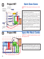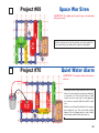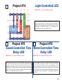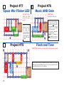
1
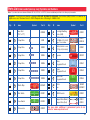
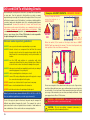
TM
Copyright © 2004 by Elenco Electronics, Inc. All rights reserved. No part of this book shall be reproduced by
any means; electronic, photocopying, or otherwise without written permission from the publisher.
REV-E
Revised 2004
753102
Table of Contents
Basic Troubleshooting
1
Advanced Troubleshooting
6
Parts List
2
Project Listings
7
How to Use It
3
Experiments 1 - 101
About Your Snap Circuits Parts
4
Other Snap Circuits Projects
45
DO’s and DON’Ts of Building Circuits
5
Snap Circuits Experiment Shapes
46
WARNING: SHOCK HAZARD - Never connect Snap Circuits to the
electrical outlets in your home in any way!
Basic Troubleshooting
1. Most circuit problems are due to incorrect assembly, always doublecheck that your circuit exactly matches the drawing for it.
2. Be sure that parts with positive/negative markings are positioned as
per the drawing.
3. Sometimes the light bulbs come loose, tighten them as needed. Use
care since glass bulbs can shatter.
4. Be sure that all connections are securely snapped.
5. Try replacing the batteries.
6. If the motor spins but does not balance the fan, check the black
plastic piece with three prongs on the motor shaft. Be sure that it is
at the top of the shaft.
Elenco Electronics is not responsible for parts damaged due to
incorrect wiring.
TM
Note: If you suspect you have damaged parts, you can follow the Advanced
Troubleshooting procedure on page 6 to determine which ones need replacing.
-1-
8 - 44
WARNING: Always check your wiring
before turning on a circuit. Never touch
the motor when it is spinning at high
speed. Never leave a circuit unattended
while the batteries are installed. Never
connect additional batteries or any other
power sources to your circuits.
BATTERIES:
Use only 1.5V AA type (not included).
Insert batteries with correct polarity.
Non-rechargeable batteries should not
be recharged. Rechargable batteries
should only be charged under adult
supervision, and should not be
recharged while in the product. Do not
mix alkaline, standard (carbon-zinc), or
rechargeable (nickel-cadmium) batteries.
Remove batteries when they are used
up. Do not short circuit the battery
terminals. Never throw batteries in a fire
or attempt to open its outer casing.
Batteries are harmful if swallowed, so
keep away from small children.
Parts List (Colors and styles may vary) Symbols and Numbers
Note: If you have the more advanced Models SC-300, SC-500, or SC-750, there are additional part lists in the other project manuals.
Important: If any parts are missing or damaged, DO NOT RETURN TO RETAILER. Call toll-free (800) 533-2441 or e-mail us at:
[email protected]. Customer Service • 150 W. Carpenter Ave. • Wheeling, IL 60090 U.S.A.
Qty.
ID
1
Name
Symbol
Part #
Qty.
ID
Name
Symbol
Part #
Base Grid
(11.0” x 7.7”)
6SCBG
1
D1
Red Light Emitting
Diode (LED)
6SCD1
3
1
1-Snap Wire
6S01
1
L1
2.5V Lamp Socket
3.2V Bulb (3.2V, 0.2A)
Type 14 or similar
6SCL1
6SCL1B
6
2
2-Snap Wire
6SC02
1
B1
Battery Holder - uses
2 1.5V type AA (not included)
6SCB1
3
3
3-Snap Wire
6SC03
1
SP
Speaker
6SCSP
1
4
4-Snap Wire
6SC04
1
U1
Music
Integrated Circuit
6SCU1
1
5
5-Snap Wire
6SC05
1
U2
Alarm
Integrated Circuit
6SCU2
1
6
6-Snap Wire
6SC06
1
U3
Space War
Integrated Circuit
6SCU3
1
WC
Whistle Chip
6SCWC
1
1
M1
Motor
Fan
6SCM1
6SCM1F
1
S1
Slide Switch
6SCS1
1
R1
100W Resistor
6SCR1
1
S2
Press Switch
6SCS2
1
1
Jumper Wire (Black)
Jumper Wire (Red)
6SCJ1
6SCJ2
1
RP
Photoresistor
6SCRP
You may order additional / replacement parts at our
website: www.snapcircuits.net
-2-
How To Use It
The Electronic Snap Circuits kit has 101 projects. They are
simple to build and understand.
The Snap Circuits kit uses building blocks with snaps to build
the different electrical and electronic circuits in the projects.
Each block has a function: there are switch blocks, lamp
blocks, battery blocks, different length wire blocks, etc. These
blocks are in different colors and have numbers on them so
that you can easily identify them. The circuit you will build is
shown in color and with numbers, identifying the blocks that
you will use and snap together to form a circuit.
For Example:
This is the switch block which is green and has the marking S1
on it as shown in the drawings. Please note that the drawing
doesn’t reflect the real switch block exactly (it is missing the ON
and OFF markings), but gives you the general idea of which
part is being used in the circuit.
To build each circuit, you have a power source block
number B1 that need two (2) “AA” batteries (not included
with the Snap Circuits kit).
A large clear plastic base grid is included with this kit to help
keep the circuit block together. You will see evenly spaced
posts that the different blocks snap into. You do not need this
base to build your circuits, but it does help in keeping your
circuit together neatly. The base has rows labeled A-G and
columns labeled 1-10.
Next to each part in every circuit drawing is a small number
in black. This tells you which level the component is placed
at. Place all parts on level 1 first, then all of the parts on level
2, then all of the parts on level 3, etc.
The 2.5V bulb comes packaged separate from its socket.
Install the bulb in the lamp socket L1 whenever that part is
used.
Place the fan on the motor M1 whenever that part is used,
unless the project you are building says not to use it.
This is a wire block which is blue and comes in different wire
lengths.
This one has the number 2 , 3 , 4 , 5 , or 6 on it
depending on the length of the wire connection required.
Some circuits use the jumper wires to make unusual
connections. Just clip them to the metal snaps or as
indicated.
There is also a 1-snap wire that is used as a spacer or for
interconnection between different layers.
Note: While building the projects, be careful not to
accidentally make a direct connection across the battery
holder (a “short circuit”), as this will damage and/or quickly
drain the batteries.
-3-
About Your Snap Circuits Parts
(Part designs are subject to change without notice).
Note: If you have the more advanced Models SC-300, SC-500, or SC-750,
there is additional information in your other project manual(s).
The base grid functions like the printed circuit boards found in most
electronic products. It is a platform for mounting parts and wires (though the
wires are usually “printed” on the board.
The blue snap wires are just wires used to connect other components, they
are used to transport electricity and do not affect circuit performance. They
come in different lengths to allow orderly arrangement of connections on the
base grid.
The red and black jumper wires make flexible connections for times when
using the snap wires would be difficult. They also are used to make
connections off the base grid (like the projects using water).
The batteries (B1) produce an electrical voltage using a chemical reaction.
This “voltage” can be thought of as electrical pressure, pushing electrical
“current” through a circuit. This voltage is much lower and much safer than
that used in your house wiring. Using more batteries increases the “pressure”
and so more electricity flows.
The slide switch (S1) connects (ON) or disconnects (OFF) the wires in a
circuit. When ON it has no effect on circuit performance.
The press switch (S2) connects (pressed) or disconnects (not pressed) the
wires in a circuit, just like the slide switch does.
W resistor (R1), “resist” the flow of electricity and
Resistors, such as the 100W
are used to control or limit the electricity in a circuit. Increasing circuit
resistance reduces the flow of electricity.
The photoresistor (RP) is a light-sensitive resistor, its value changes from
nearly infinite in total darkness to about 1000W when a bright light shines on it.
A light bulb, such as in the 2.5V lamp (L1), contains a special wire that glows
bright when a large electric current passes through it. Voltages above the
bulb’s rating can burn out the wire.
The motor (M1) converts elecricity into mechanical motion. Electricity is
closely related to magnetism, and an electric current flowing in a wire has a
magnetic field similar to that of a very, very tiny magnet. Inside the motor is
three coils of wire with many loops. If a large electric current flows through
the loops, the magnetic effects become concentrated enough to move the
coils. The motor has a magnet inside so, as the electricity moves the coils to
align them with the permanent magnet, the shaft spins.
The speaker (SP) converts electricity into sound. It does this by using the
energy of a changing electrical signal to create mechanical vibrations (using
a coil and magnet similar to that in the motor), these vibrations create
variations in air pressure which travel across the room. You “hear” sound
when your ears feel these air pressure variations.
The whistle chip (WC) contains two thin plates. When an electrical signal is
applied across them they will stretch slightly in an effort to separate (like two
magnets opposing each other), when the signal is removed they come back
together. If the electrical signal applied across them is changing quickly, then
the plates will vibrate. These vibrations create variations in air pressure that
your ears feel just like sound from a speaker.
The LED (D1) is a light emitting diode, and may be thought of as a special
one-way light bulb. In the “forward” direction (indicated by the “arrow” in the
symbol) electricity flows if the voltage exceeds a turn-on threshold (about
1.5V); brightness then increases. A high current will burn out the LED, so the
current must be limited by other components in the circuit. LEDs block
electricity in the “reverse” direction.
Some types of electronic components can be super-miniaturized, allowing
many thousands of parts to fit into an area smaller that your fingernail. These
“integrated circuits” (ICs) are used in everything from simple electronic toys to
the most advanced computers. The music, alarm, and space war ICs (U1,
U2, and U3) in Snap Circuits are actually modules containing specialized
sound-generation ICs and other supporting components (resistors,
capacitors, and transistors) that are always needed with them. This was done
to simplify the connections you need to make to use them. The descriptions
for these modules are given here for those interested, see the projects for
connection examples:
Music IC:
TRG
HLD
(+) - power from batteries
(–) - power return to batteries
OUT - output connection
HLD - hold control input
TRG - trigger control input
(–)
OUT
Music for ~20 sec on power-up, then hold HLD to (+) power
or touch TRG to (+) power to resume music.
(+)
Alarm IC:
IN2
IN1, IN2, IN3 - control inputs
(–) - power return to batteries
OUT - output connection
IN1
IN3
(–)
OUT
(+)
OUT
(+) - power from batteries
(–) - power return to batteries
OUT - output connection
IN1, IN2 - control inputs
IN2
Connect each control input to (–) power to sequence through
8 sounds.
Connect control inputs to (+) power to make five alarm
sounds, see project 22 for configurations.
Space War IC:
IN1
(–)
-4-
DO’s and DON’Ts of Building Circuits
After building the circuits given in this booklet, you may wish to experiment
on your own. Use the projects in this booklet as a guide, as many
important design concepts are introduced throughout them. Every circuit
will include a power source (the batteries), a resistance (which might be
a resistor, lamp, motor, integrated circuit, etc.), and wiring paths between
them and back. You must be careful not to create “short circuits” (very
low-resistance paths across the batteries, see examples below) as this
will damage components and/or quickly drain your batteries. Only
connect the ICs using configurations given in the projects, incorrectly
doing so may damage them. Elenco Electronics is not responsible
for parts damaged due to incorrect wiring.
TM
Here are some important guidelines:
ALWAYS use eye protection when experimenting on your own.
Examples of SHORT CIRCUITS - NEVER DO THESE!!!
Placing a 3-snap wire directly
across the batteries is a
SHORT CIRCUIT.
!
!
NEVER
DO!
NEVER
DO!
This is also a
SHORT CIRCUIT.
When the switch (S1) is turned on, this large circuit has a SHORT
CIRCUIT path (as shown by the arrows). The short circuit prevents any
other portions of the circuit from ever working.
ALWAYS include at least one component that will limit the current
through a circuit, such as the speaker, lamp, whistle chip, ICs
(which must be connected properly), motor, photoresistor, or
resistor.
!
ALWAYS use the LED and switches in conjunction with other
components that will limit the current through them. Failure to
do so will create a short circuit and/or damage those parts.
NEVER
DO!
ALWAYS disconnect your batteries immediately and check your wiring if
something appears to be getting hot.
ALWAYS connect ICs using configurations given in the projects or as per
the connection descriptions for the parts.
!
!
ALWAYS check your wiring before turning on a circuit.
NEVER
DO!
NEVER
DO!
NEVER connect to an electrical outlet in your home in any way.
NEVER leave a circuit unattended when it is turned on.
NEVER touch the motor when it is spinning at high speed.
Note: If you have the more advanced Models SC-300, SC-500, or SC-750,
there are additional guidelines in your other project manual(s).
For all of the projects given in this book, the parts may be arranged in
different ways without changing the circuit. For example, the order of
parts connected in series or in parallel does not matter — what matters is
how combinations of these sub-circuits are arranged together.
-5-
You are encouraged to tell us about new circuits you create. Upon review,
we will post them with your name, age, and hometown in a special section
on our website. If we use them in future manual revisions, we will send
you a copy of the manual so you can show your family and friends. Send
your suggestions to Elenco Electronics.
TM
WARNING: SHOCK HAZARD - Never connect Snap Circuits to
the electrical outlets in your home in any way!
!
CAUTION: Do not mix alkaline, standard (carbon-zinc), or
rechargeable (nickel-cadmium) batteries.
Advanced Troubleshooting
(Adult supervision recommended)
Elenco Electronics is not responsible for parts damaged due to
incorrect wiring.
TM
If you suspect you have damaged parts, you can follow
this procedure to systematically determine which ones
need replacing:
1. 2.5V lamp (L1), motor (M1), speaker (SP), and battery holder
(B1): Place batteries in holder and install bulb in lamp socket.
Place the 2.5V lamp directly across the battery holder, it should
light. Do the same with the motor (motor + to battery +), it should
spin to the right at high speed. “Tap” the speaker across the
batttery holder contacts, you should hear static as it touches. If
none work then replace your batteries and repeat, if still bad then
the battery holder is damaged.
2. Jumper wires: Use this minicircuit to test each jumper wire,
the lamp should light.
6. Alarm IC (U2): Build project 17, you should hear a siren. Then
place a 3-snap wire between grid locations A1 and C1, the
sound is different. Then move the 3-snap from A1-C1 to A3-C3
to hear a 3rd sound.
7. Music IC (U1): Build project 74 but use the press switch (S2) in
place of the photoresistor (RP). Turn it on and the LED (D1)
flickers for a while and stops, it resumes if you press and hold
down the press switch. Then touch a 3-snap wire across base
grid points A1 and C1 and the flickering resumes for a while.
8. Space war IC (U3) and photoresistor (RP): Build project 19,
both switches (S1 and S2) should change the sound. Then
replace either switch with the photoresistor, waving your hand
over it should change the sound.
9. Whistle chip (WC): Build project 61 and if there is light on the
photoresistor (RP) then you will hear sound from the whistle
chip.
Note: If you have the more advanced models SC-300, SC-500, or
SC-750, there are additional tests in your other project manual(s).
3. Snap wires: Use this minicircuit to test each of the snap
wires, one at a time. The lamp
should light.
4. Slide switch (S1) and Press switch (S2): Build project 1, if the
lamp (L1) doesn’t light then the slide switch is bad. Replace the
slide switch with the press switch to test it.
W resistor (R1) and LED (D1): Build project 7 except
5. 100W
initially use the speaker (SP) in place of the LED, you will hear
static if the resistor is good. Then replace the speaker with the
LED and see that it lights.
Elenco Electronics, Inc.
TM
150 W. Carpenter Avenue
Wheeling, IL 60090 U.S.A.
Phone: (847) 541-3800
Fax: (847) 520-0085
e-mail: [email protected]
Web Site: www.elenco.com
You may order additional / replacement parts at:
www.snapcircuits.net
-6-
Project Listings
Project #
1
2
3
4
5
6
7
8
9
10
11
12
13
14
15
16
17
18
19
20
21
22
23
24
25
26
27
28
29
30
31
32
33
34
-7-
Description
Electric Light & Switch
DC Motor & Switch
Sound Activated Switch
Adjusting Sound Level
Lamp & Fan in Series
Lamp & Fan in Parallel
Light Emitting Diode
One Direction for LED
Conduction Detector
Space War Alarm Combo
Flying Saucer
Decreasing Saucer Lift
Two-Speed Fan
The Fuse
Musical Doorbell
Momentary Alarm
Alarm Circuit
Laser Gun
Space War
Light Switch
Paper Space War
Light Police Siren
More Loud Sounds
More Loud Sounds (II)
More Loud Sounds (III)
More Loud Sounds (IV)
Clap Sounds
More Clap Sounds
More Clap Sounds (II)
More Clap Sounds (III)
More Clap Sounds (IV)
Voice Light Diode
Voice Control
Motor Space Sounds
Page #
8
8
9
9
10
10
11
11
12
12
13
13
14
14
15
15
16
16
17
17
17
18
18
18
18
18
19
19
19
19
19
20
20
20
Project #
35
36
37
38
39
40
41
42
43
44
45
46
47
48
49
50
51
52
53
54
55
56
57
58
59
60
61
62
63
64
65
66
67
68
Description
Page #
Motor Space Light
20
Space Battle (II)
21
Silent Space Battle
21
Periodic Sounds
21
Blinking Double Flashlight
21
Motor-Controlled Sounds
22
More Motor Sounds
22
More Motor Sounds (II)
22
More Motor Sounds (III)
22
More Motor Sounds (IV)
22
Light-Controlled Flicker
23
More Sound Effects
23
This OR That
24
This AND That
24
Neither This NOR That
25
NOT This AND That
25
Reflection Detector
26
Quieter Reflection Detector
26
Flashing Laser Light with Sound 27
Space War Flicker
27
Spinning Rings
28
Strobe the House Lights
28
Race Game
29
Using Parts as Conductors
29
Spin Draw
30
Space War Flicker Motor
30
Light-Controlled Sounds
31
Light-Controlled Sounds (II)
31
Light-Controlled Sounds (III)
31
Light-Controlled Sounds (IV)
31
Light-Controlled Sounds (V)
31
Electronic Bombing Game
32
Quiet Zone Game
33
Space War Music Combo
33
Project #
69
70
71
72
73
74
75
76
77
78
79
80
81
82
83
84
85
86
87
88
89
90
91
92
93
94
95
96
97
98
99
100
101
Description
Page #
Space War Siren
34
Quiet Water Alarm
34
Light-Controlled Lamp
35
Voice-Controlled Lamp
35
Motor-Controlled Lamp
35
Light-Controlled LED
36
Sound-Controlled Time Delay LED 36
Motor-Controlled Time Delay LED 36
Space War Flicker LED
37
Music AND Gate
37
Flash and Tone
37
Lamp, Speaker & Fan in Parallel 38
Pencil Alarm
38
Pencil Alarm Variants
38
Fun with the Alarm IC
39
Motor Sounds Combo
39
Motor Sounds Combo (II)
39
Music Alarm Combo
40
Bomb Sound
40
Bomb Sound (II)
40
Light-Controlled LED (II)
41
Touch Light
41
Touch Sound
41
Water Space War
42
Water Space War (II)
42
Human Space War
42
Noisier Water Space War
43
Light/Water Space War
43
OR/AND Space War Light
43
Simple Water Alarm
44
Simple Salt Water Alarm
44
Ambulance Water Alarm
44
Ambulance Contact Alarm
44
Project #1
Electric Light & Switch
OBJECTIVE: To show how electricity is turned “ON” or “OFF”
with a switch.
Build the circuit shown on the left by placing all the parts with a black 1
next to them on the board first. Then, assemble parts marked with a 2.
Install two (2) “AA” batteries (not included) into the battery holder (B1)
and screw the bulb into the lamp socket (L1) if you have not done so
already.
When you close the slide switch (S1), current flows from the batteries
through the lamp and back to the battery through the switch. The closed
switch completes the circuit. In electronics this is called a closed circuit.
When the switch is opened, the current can no longer flow back to the
battery, so the lamp goes out. In electronics this is called an open circuit.
Project #2
DC Motor & Switch
OBJECTIVE: To show how electricity is used to run a Direct
Current (DC) Motor.
Build the circuit shown on the left by placing all the parts with a black 1
next to them on the board first. Then, assemble parts marked with a 2.
When you close the switch (S1), current flows from the batteries
through the motor making it rotate. Place the fan blade on the motor
shaft and close the slide switch (S1). The motor will rotate forcing the
fan blade to move air past the motor.
In this project, you changed electrical power into mechanical power.
DC motors are used in all the battery powered equipment requiring
rotary motion, such as a cordless drill, electric tooth brush, and toy
trains that run on batteries just to name a few. An electric motor is
much easier to control than gas or diesel engines.
!
WARNING: Moving parts. Do not touch the fan or
motor during operation.
-8-
Project #3
Sound Activated Switch
OBJECTIVE: To show how sound can turn “ON” an electronic
device.
Build the circuit shown on the left by placing all the parts with a black 1
next to them on the board first. Then, assemble parts marked with a 2.
Finally, lay the speaker on the table and connect it to the circuit using
the jumper wires as shown.
When you close the slide switch (S1), the music may play for a short
time, and then stop. After the music has stopped, clap your hands
close to the whistle chip or tap the base with your finger. The music
should play again for a short time, then stop. Blow on the whistle chip
and the music should play.
You could connect the speaker using snap wires instead of the jumper
wires, but then the speaker may create enough sound vibrations to reactivate the whistle chip.
Project #4
Adjusting Sound Level
OBJECTIVE: To show how resistance can lower the sound from
the speaker.
Build the circuit shown on the left. When you close the slide switch
(S1), the music may play for a short time and then stop. After the
music has stopped, clap your hands close to the whistle chip or tap the
base with your finger. The music should play again for a short time,
then stop.
In this project, you changed the amount of current that goes through
the speaker and reduced the sound output of the speaker. Resistors
are used throughout electronics to limit the amount of current that
flows.
-9-
Project #5
Lamp & Fan in Series
OBJECTIVE: To show how a lamp can indicate when a fan is
running.
Build the circuit shown on the left by placing all the parts with a black 1
next to them on the board first. Then, assemble parts marked with a 2.
Finally, place the fan blade on the motor.
When you close the slide switch (S1), the fan will spin and the light
should turn on. The fan will take a while to start turning due to inertia.
Inertia is the property that tries to keep a body at rest from moving and
tries to keep a moving object from stopping.
The light helps protect the motor from getting the full voltage when the
switch is closed. Part of the voltage goes across the light and the rest
goes across the motor. Remove the fan and notice how the light gets
dimmer when the motor does not have to spin the fan blade.
!
Project #6
WARNING: Moving parts. Do not touch the fan or
motor during operation.
Lamp & Fan in Parallel
OBJECTIVE: To show how an indicator light can be connected
without affecting the current in the motor.
Build the circuit shown on the left.
When you close the slide switch (S1), both the fan and the light should
turn on. The fan will take a while to start turning due to inertia. In this
connection, the lamp does not change the current to the motor. The
motor should start a little faster than in Project #5.
Remove the fan and notice how the light does not change in
brightness as the motor picks up speed. It has its own path to the
battery.
!
WARNING: Moving parts. Do not touch the fan or
motor during operation.
-10-
Project #7
Light Emitting Diode
OBJECTIVE: To show how a resistor and LED are wired to emit
light.
Build the circuit shown on the left by placing all the parts with a black 1
next to them on the board first. Then, assemble parts marked with a 2.
When you close the slide switch (S1), current flows from the batteries
through the switch, through the resistor, through the LED (light emitting
diode) and back to the battery. The closed switch completes the circuit.
The resistor limits the current and prevents damage to the LED.
NEVER PLACE AN LED DIRECTLY ACROSS THE BATTERY! If no
resistor is in the circuit, the battery may push enough current through
the LED to damage the semiconductor that is used to produce the light.
LEDs are used in all types of electronic equipment to indicate
conditions and pass information to the user of that equipment.
Can you think of something you use everyday that has an LED in it?
Project #8
One Direction for LED
OBJECTIVE: To show how electricity can only pass in one
direction through an LED.
Rebuild the circuit used in Project #7 but put the LED in as shown on
the left.
When you close the slide switch (S1), current should flow from the
batteries through the resistor and then through the LED. When current
flows through an LED, it lights up. Since the LED is in backwards,
current cannot flow. The LED is like a check valve that lets current flow
in only one direction.
In this project, you changed the direction for current through the LED.
An electronic component that needs to be connected in one direction is
said to have polarity. Other parts like this will be discussed in future
projects. Placing the LED in backwards does not harm it because the
voltage is not large enough to break down this electronic component.
-11-
Project #9
Conduction Detector
OBJECTIVE: To make a circuit that detects the conduction of
electricity in different materials.
Rebuild the circuit from Project #7 but leave the on-off switch out as
shown on the left.
When you place a paper clip across the terminals as shown in the
picture on the left, current flows from the batteries through the resistor,
through the LED, and back to the battery. The paper clip completes
the circuit and current flows through the LED. Place your fingers
across the terminals and the LED does not light. Your body is too high
of a resistance to allow enough current to flow to light the LED. If the
voltage, which is electrical pressure, was higher, current could be
pushed through your fingers and the LED would light. This detector
can be used to see if a material like plastic is a good conductor or a
poor conductor.
Project #10
Space War Alarm Combo
OBJECTIVE: To combine the sounds from the space war and
alarm integrated circuits.
Build the circuit shown and add the jumpers to complete it. Turn it on,
press the press switch (S2) several times, and wave your hand over
the photoresistor (RP) to hear all the sound combinations. If the sound
is too loud you may replace the speaker (SP) with the whistle chip
(WC).
-12-
Project #11
Flying Saucer
OBJECTIVE: To make a circuit that launches the fan blade to
simulate a flying saucer.
Rebuild the circuit from Project #2, but reverse the polarity on the motor
so the negative (–) on the motor goes to the positive (+) on the battery.
When you close the slide switch (S1), the motor will slowly increase in
speed. When the motor has reached maximum rotation, turn the slide
switch (S1) off. The fan blade should rise and float through the air like
a flying saucer. Be careful not to look directly down on fan blade when
it is spinning.
The air is being blown down through the blade and the motor rotation
locks the fan on the shaft. When the motor is turned off, the blade
unlocks from the shaft and is free to act as a propeller and fly through
the air. If speed of rotation is too slow, the fan will remain on motor
shaft because it does not have enough lift to propel it. The motor will
spin faster when both batteries are new.
!
WARNING: Moving parts. Do not
touch the fan or motor during operation.
!
WARNING: Do not
lean over the motor.
Project #12
If the fan doesn’t fly off, then turn the switch on and off several times
rapidly when it is at full speed.
Decreasing Saucer Lift
OBJECTIVE: To show how voltage affects speed of a DC motor
and can decrease the lift of the saucer.
Change the circuit in Project #11 by adding the lamp (L1) in series with
the motor as shown in the diagram on the left.
When you place the lamp in series with any electronic device, it will
draw less current because it adds resistance. In this case, the lamp in
series reduces the current through the motor, and that reduces the top
speed of the motor. Close the slide switch (S1), and wait until the fan
reaches maximum speed. Open the switch and observe the difference
in the height due to the lamp. In most cases, it may not even launch.
-13-
!
WARNING: Moving parts. Do not touch the fan or
motor during operation.
!
WARNING: Do not lean over the motor.
Project #13
Two-Speed Fan
OBJECTIVE: To show how switches can increase or decrease
the speed of an electric fan.
Build the circuit shown on the left by placing all the parts with a black
1 next to them on the board first. Then, assemble parts marked with
a 2. Finally, add the 2-snap wires that are marked for level three.
!
WARNING:
Moving
parts. Do not touch
the fan or motor during
operation.
When you close the slide switch (S1), current flows from the batteries
through the slide switch (S1), motor (M1), the lamp (L1), and back to
the battery (B1). When the press switch (S2) is closed, the lamp is
shorted and motor speed increases.
The principle of removing resistance to increase motor speeds is only
one way of changing the speed of the motor. Commercial fans do not
use this method because it would produce heat in the resistor and fans
are used to cool circuits by moving air over them. Commercial fans
change the amount of voltage that is applied to the motor using a
transformer or other electronic device.
Project #14
The Fuse
OBJECTIVE: To show how a fuse is used to break all current
paths back to the voltage source.
Use the circuit built in Project #13.
!
WARNING:
Moving
parts. Do not touch
the fan or motor during
operation.
When you close the slide switch (S1), current flows from the batteries
through the slide switch (S1), the lamp (L1), motor (M1), and back to the
battery (B1). Pretend the 2-snap wire marked fuse in the drawing on the
left is a device that will open the circuit if too much current is taken from
the battery. When press switch (S2) is closed, the light is shorted and
motor speed increases due to an increase in current to the motor. While
still holding press switch (S2) down, remove the 2-snap wire marked
fuse and notice how everything stops. Until the fuse is replaced, the
open circuit path protects the electronic parts. If fuses did not exist,
many parts could get hot and even start fires. Replace the 2-snap wire
and the circuit should return to normal.
Many electronic products in your home have a fuse that will open when
too much current is drawn. Can you name some?
-14-
Project #15
Musical Doorbell
OBJECTIVE: To show how an integrated circuit can be used as
a musical doorbell.
Build the circuit shown on the left. When you close the slide switch
(S1), the music integrated circuit (U1) may start playing one song then
stop. Each time you press the press switch “doorbell button” (S2) the
song will play again and stop. Even if you let go of the press switch
(S2), the integrated circuit keeps the song playing until it has reached
the end of the song.
Musical integrated circuits are used to entertain young children in
many of the toys and chairs made to hold infants. If the music is
replaced with words, the child can also learn while they are
entertained. Because of great advances in miniaturization, many
songs are stored in a circuit no bigger than a pinhead.
Project #16
Momentary Alarm
OBJECTIVE: To show how integrated circuits can also create
loud alarm sounds in case of emergencies.
Modify the circuit used in Project #15 to look like the one shown on the
left.
When you close the slide switch (S1), the music integrated circuit (U1)
may start playing one song then stop. The song will be much louder
than in the previous project because it is now being used as an alarm.
Each time you press the press switch “alarm button” (S2) after the
song stops playing, the song will play again, but only while you hold
the button down.
-15-
Project #17
Alarm Circuit
OBJECTIVE: To show how an integrated circuit can be used to
make real alarm sounds.
Build the circuit shown on the left by placing all the parts with a black 1
next to them on the board first. Then, assemble parts marked with a 2.
When you close the slide switch (S1), the integrated circuit should start
sounding a very loud alarm sound. This integrated circuit is designed
to sweep through all the frequencies so even hard of hearing people
can be warned by the alarm.
If the alarm sound was passed through an amplifier and installed into
a police car, it would also serve as a good police siren.
Project #18
Laser Gun
OBJECTIVE: To show how integrated circuits sound can easily
be changed to exciting space war sounds.
Build the circuit shown on the left by placing all the parts with a black
1 next to them on the board first. Then, assemble parts marked with
a 2.
When you close the slide switch (S1), the integrated circuit should
start sounding a laser gun sound. This integrated circuit is designed
to produce different sounds that can easily be changed. You can even
switch the sound on and off quickly to add sound effects to your games
or recordings.
-16-
Project #19
Space War
OBJECTIVE: To introduce you to the space war integrated
circuit and the sounds it can make.
Build the circuit shown on the left, which uses the space war integrated
circuit. Activate it by flipping the switch or pressing the press switch,
do both several times and in combination. You will hear an exciting
range of sounds, as if a space war is raging!
Like the other integrated circuits, the space war IC is a superminiaturized electronic circuit that can play a variety of cool sounds
stored in it by using just a few extra components.
In movie studios, technicians are paid to insert these sounds at the
precise instant a gun is fired. Try making your sound occur at the
same time an object hits the floor. It is not as easy as it sounds.
Project #20 Light Switch
OBJECTIVE: To show how light
can control a circuit using a
photoresistor.
Use the circuit from Project #19 above, but replace the slide switch (S1)
with the photoresistor (RP). The circuit immediately makes noise. Try
turning it off. If you experiment, then you can see that the only ways to
turn it off are to cover the photoresistor, or to turn off the lights in the
room (if the room is dark). Since light is used to turn on the circuit, you
might say it is a "light switch".
The photoresistor contains material that changes its resistance when it
is exposed to light. As it gets more light, the resistance of the
photoresistor decreases. Parts like this are used in a number of ways
that affect our lives. For example, you may have streetlights in your
neighborhood that turn on when it starts getting dark and turn off in the
morning.
-17-
Project #21 Paper Space War
OBJECTIVE: To give a more dramatic demonstration of using the
photoresistor.
Use the same circuit as for Project #20. Find a piece of white paper that
has a lot of large black or dark areas on it, and slowly slide it over the
photosensitive resistor. You should hear the sound pattern constantly
changing, as the white and dark areas of the paper control the light to
the photosensitive resistance. You can also try the pattern below or
something similar to it:
Project #22
Light Police Siren
OBJECTIVE: To build a police siren that is controlled by light.
Build the circuit shown on the left by placing all the parts with a black
1 next to them on the board first. Then, assemble parts marked with
a 2. Finally, insert the parts with a 3 last on level 3.
Cover the photoresistor (RP) and turn on the switch (S1). A police
siren with music is heard for a while and stops, then you can control it
by covering or uncovering the photoresistor.
Project #23
Project #24
Project #25
Project #26
OBJECTIVE:
To show
variations of the circuit in
Project #22.
OBJECTIVE:
To show
variations of the circuit in
Project #22.
OBJECTIVE:
To show
variations of the circuit in
Project #22.
OBJECTIVE:
To show
variations of the circuit in
Project #22.
Modify the Project #22 by
connecting points X & Y. The
circuit works the same way but
now it sounds like a machine
gun with music.
Now remove the connection
between X & Y and then make a
connection between T & U. The
circuit works the same way but
now it sounds like a fire engine
with music.
Now remove the connection
between T & U and then make a
connection between U & Z. The
circuit works the same way but
now it sounds like an ambulance
with music.
Now remove the connections
between U & Z and between V &
W, then make a connection
between T & U. The circuit
works the same way but now it
sounds like a familiar song but
with static.
More Loud More Loud More Loud More Loud
Sounds
Sounds (II) Sounds (III) Sounds (IV)
-18-
Project #27
Clap Sounds
OBJECTIVE: To build a police siren and other sounds that are
controlled by clapping your hands.
Build the circuit shown on the left by placing all the parts with a black
1 next to them on the board first. Then, assemble parts marked with
a 2.
Turn on the slide switch (S1) and a police siren is heard and then
stops, clap your hands and it will play again. Note however that music
can be heard faintly in the background of the siren. If clapping does
not trigger the sound, tap the whistle chip with your finger.
Project #28
Project #29
Project #30
Project #31
OBJECTIVE: To show how
ICs can do many jobs.
OBJECTIVE: To show how
ICs can do many jobs.
OBJECTIVE: To show how
ICs can do many jobs.
OBJECTIVE: To show how
ICs can do many jobs.
Modify the last circuit by
connecting points X & Y. The
circuit works the same way but
now it sounds like a machine
gun.
Now remove the connection
between X & Y and then make a
connection between T & U. The
circuit works the same way but
now it sounds like a fire engine.
Now remove the connection
between T & U and then make a
connection between U & Z. The
circuit works the same way but
now it sounds like an
ambulance.
Now remove the connections
between U & Z and between V &
W, then make a connection
between T & U. The circuit
works the same way but now it
sounds like a familiar song but
with static.
More Clap
Sounds
-19-
More Clap More Clap More Clap
Sounds (II) Sounds (III) Sounds (IV)
Project #32
Voice Light Diode
OBJECTIVE: To build a
circuit that uses your voice
to control a light emitting
diode.
Build the circuit shown on the
left and turn on the switch.
The LED (D1) may be on for
a while and then turn off.
Clap or talk loud and the
diode will light again and
keep flickering for a little
while.
Project #34 Motor Space Sounds
OBJECTIVE: To build a
circuit that uses a motor to
activate space war sounds.
Turn it on and wait for any
sounds to stop then spin the
motor and the sounds play
again.
Do you know why turning the
motor makes the sound
play? Actually, the DC motor
is also a DC generator and
when you turn it, the motor
generates a voltage that
triggers the sound circuits.
Project #33
Voice Control
OBJECTIVE: To use your voice
to control sounds.
The preceding circuit probably did
not seem too exciting; so replace
the LED (D1) with the speaker
(SP). You hear a range of exciting
sounds. Clap or talk loud and the
sounds will resume.
If you find that the sound does not
turn off, then vibrations created by
the speaker may be activating the
whistle chip. Set the speaker on the
table near the circuit and connect it
to the same locations using the
jumper wires to prevent this.
Project #35
Motor
Space Light
OBJECTIVE: To build a circuit
that uses a motor to activate a
light diode.
This circuit is loud and may bother
other people around you so
replace the speaker with the LED
(D1), (position it like in Project 32);
the circuit operates in the same
manner.
-20-
Project #36
Space Battle (II)
OBJECTIVE:
To show
another way of using the
space war integrated circuit.
Build the circuit shown on the
left, which is based on the
circuit in the Space War
Project #19. Turn on the
switch and you will hear
exciting sounds, as if a space
battle is raging!
The motor is used here as a
3-snap wire, and will not spin.
!
Project #38
WARNING:
Moving
parts. Do not touch
the fan or motor during
operation.
Periodic Sounds
OBJECTIVE: To build a circuit with
light and sound that change and repeat.
Build the circuit shown on the left and turn
it on. The lamp alternates between being
on and off while the speaker alternates
between two musical tones . . . like
someone is flipping a switch, but at a very
consistent rate. Periodic signals like this
are very important in electronics.
-21-
Project #37
Silent Space
Battle
OBJECTIVE: To show another
way of using the space war part.
The preceding circuit is loud and may
bother people around you, so replace
the speaker (SP) with the LED (D1),
position it as in Project #32. Now you
have a silent space battle.
!
WARNING:
Moving
parts. Do not touch
the fan or motor during
operation.
Project #39
Blinking
Double
Flashlight
OBJECTIVE: To build a circuit with two
lights that alternate.
In the circuit at left, replace the speaker
(SP) with an LED (D1); position it as in
Project #32. The lamp alternates between
being on and off while the LED alternates
between being dimmer and brighter.
Project #40
Motor-Controlled Sounds
OBJECTIVE:
circuits.
To show how motion can trigger electronic
This circuit is controlled by spinning the motor with your hands. Turn
on the switch. A police siren is heard and then stops. Spin the motor
and it will play again. Note however, that music can be heard faintly in
the background of the siren.
Project #41
Project #42
Project #43
Project #44
More Motor
Sounds
More Motor
Sounds (II)
More Motor
Sounds (III)
More Motor
Sounds (IV)
OBJECTIVE: To show how
motion can trigger electronic
circuits.
OBJECTIVE: To show how
motion can trigger electronic
circuits.
OBJECTIVE: To show how
motion can trigger electronic
circuits.
OBJECTIVE: To show how
motion can trigger electronic
circuits.
Modify the last circuit by
connecting points X & Y with the
lamp (L1). The circuit works the
same way but now it sounds like
a machine gun.
Now remove the connection
between X & Y and then make a
connection between T & U with
the lamp (L1). The circuit works
the same way but now it sounds
like a fire engine.
Now remove the connection
between T & U and then make a
connection between U & Z with
the lamp (L1). The circuit works
the same way but now it sounds
like an ambulance.
Now remove the connections
between U & Z and between V &
W, then make a connection
between T & U. The circuit
works the same way but now it
sounds like a familiar song but
with static.
-22-
Project #45
Light-Controlled Flicker
OBJECTIVE: To make a circuit that uses light to control the
blinking of another light.
This circuit does not use the noisy speaker it uses a nice quiet LED.
Turn on the switch, the LED flickers. Wait a few seconds, then cover
the photoresistor and the flicker stops. The flicker is controlled by the
photoresistor, uncover it and the flicker resumes.
People that are deaf need lights to tell them when a doorbell is ringing.
They also use circuits like this to tell them if an alarm has been
triggered or an oven is ready.
Can you think of other uses?
Project #46
More Sound Effects
OBJECTIVE: To investigate the different sound effects available
from the alarm integrated circuit.
Build the circuit shown on the left. When you close the slide switch
(S1), the integrated circuit should start sounding an up-down siren.
This is just one more sound effect that this integrated circuit is
designed to produce. Different sounds that can easily be changed are
very important when designing games and toys. Switch the sound on
and off quickly and see if you can create even different effects. This
mode will create many robotic sounds if switched quickly.
-23-
Project #47
This OR That
OBJECTIVE: To introduce you to the OR concept of electronic
wiring.
Build the circuit shown. Notice that if you turn on the slide switch (S1)
OR press the press switch (S2) the LED lights up. There is no partially
lit state here, the diode is either totally on or totally off. While this may
seem very simple and boring, it represents an important concept in
electronics. Two switches like this may be used to turn on a light in
your house, or they might be two sensors at a railroad crossing used
to start the ding-ding sound and lower the gate. You could also have
more than two switches and the circuit would function the same way.
Project #48
This AND That
OBJECTIVE: To introduce you to digital circuits.
Build the circuit shown. Notice that if you turn on the slide switch (S1)
AND press the press switch (S2) the LED lights up. Once again, there
is no partially lit state here, the LED is either totally on or totally off.
Two switches like this may be used to turn on the same light in your
house, the room switch and the master switch in the electrical box. You
could also have more than two switches and the circuit would function
the same way.
Combinations of AND and OR circuits are used to add and multiply
numbers together in modern computers. These circuits are made of
tiny transistors in massive integrated circuits.
-24-
Project #49
Neither This NOR That
OBJECTIVE: To demonstrate the concept of a NOR circuit.
Build the circuit at left and test the combinations of the slide switch
(S1) and press switch (S2). If you compare it to the OR circuit in
Project #47, you can see the LED lights in the opposite combinations
of that circuit. Hence, we refer to it as a NOR circuit (short for “NOT
this OR that”). Like the OR and AND, it is an important building block
in computers.
Project #50
NOT This AND That
OBJECTIVE: To demonstrate the concept of a NAND circuit.
Build the circuit at left and test the combinations of the slide switch
(S1) and press switch (S2). If you compare it to the AND circuit in
Project #48, you can see the LED lights in the opposite combinations
of that circuit. Hence, we refer to it as a NAND circuit (short for “NOT
this AND that”). This circuit can also have more or less than two
inputs, though when it only has one input it is referred to as a NOT
circuit. Like the OR, AND, and NOR, NAND and NOT are important
building blocks in computers.
-25-
Project #51
Reflection Detector
OBJECTIVE: To detect if a mirror is present.
Build the circuit at left. Place it where there won’t be any room light
hitting the photoresistor (RP) (such as in a dark room or under a table),
and then turn it on. The 2.5V lamp (L1) will be bright but there should
be little or no sound.
Take a small mirror and hold it over the lamp and photoresistor. You
should hear sound now. You have a reflection detector! The more light
that gets reflected like this, the louder the sound. You can try holding
the mirror at different angles and distances and see how the sound
changes. You can also hold a white piece of paper over them, since
white surfaces reflect light.
Project #52
Quieter Reflection Detector
OBJECTIVE: To detect a mirror.
Let’s modify the reflection detector circuit so that it is not so loud and
annoying. We’ll also put a lamp on it that can be seen in a noisy room.
Build the circuit at left. Place it somewhere where there won’t be any
room light hitting the photoresistor (such as in a dark room or under a
table), and then turn it on. The 2.5V lamp will be bright but there
should be little or no sound.
Take a small mirror and hold it over the lamp and photoresistor. You
should hear sound now as the mirror onto the photoresistor reflects
light from the lamp. The more light that gets reflected like this, the
louder the sound. You can also hold a white piece of paper over the
circuit, since white surfaces reflect light.
-26-
Project #53
Flashing Laser Light
with Sound
OBJECTIVE: To build the circuit used in a toy laser gun with
flashing laser light and trigger.
When you press the press switch (S2), the integrated circuit should
start sounding a very loud laser gun sound. The red LED will flash
simulating a burst of laser light. You can shoot long repeating laser
burst, or short zaps by tapping the trigger switch.
Project #54
Space War Flicker
OBJECTIVE: To build a circuit using the space war IC to make
exciting sounds.
Build the circuit shown on the left, which uses the Space War
integrated circuit.
Set the switch on and the speaker makes exciting sounds. The output
of the IC can control lights, speakers, and other low power devices.
You may replace the speaker (SP) with the 2.5V lamp (L1), and the
bulb will flicker. You can also use the LED (D1) in place of the lamp
(position it with the “+” side towards the 6-snap).
-27-
Project #55
Spinning Rings
OBJECTIVE: To build an electronic spinner.
Setup: Cut out the disc on page 46 that looks like the one shown
here. Using Scotch tape, attach the disc with the printed side up on
the top of the fan blade. Place the blade on the motor as shown to the
left and below.
When the press switch (S2) is pressed, the arcs will turn into colored
rings with a black background. Notice how the color drops in
brightness when it is stretched to make a complete circle.
!
WARNING: Moving parts. Do not touch the fan or
motor during operation.
Project #56
Strobe the House Lights
OBJECTIVE: To use the spinner to see strobe effect due to 60
cycles.
Use the circuit from Project #55.
Setup: Place the spinning rings under a fluorescent light that runs on
normal house current. Start the disc spinning and release the press
switch (S2). As the speed changes you will notice the white lines first
seem to move in one direction then they start moving in another
direction. This effect is because the lights are blinking 60 times a
second and the changing speed of the motor is acting like a strobe
light to catch the motion at certain speeds. To prove this, try the same
test with a flashlight. The light from a flashlight is constant and if all
other lights are out, you will not see the effect that looks like a
helicopter blade in a movie. Some fluorescent lights use an electronic
ballast and they also produce a constant light.
!
WARNING: Moving parts. Do not touch the fan or
motor during operation.
-28-
Project #57
Race Game
OBJECTIVE: Build an electronic game for racing.
!
WARNING:
Moving
parts. Do not touch
the fan or motor during
operation.
Project #58
Modify Project #56 by adding the pointer as shown on the left. The paper should
be cut from page 46 and taped high enough on the speaker so the pointer will stick
over the fan with paper. Bend the pointer at a right angle as shown on the left.
Setup: Cut out the grid with four (4) colors from page 46 and place it under the
base as shown on the left. Each player picks a color (or two colors if only 2 people
are playing) and places a single snap on row G. The purple player in column 1,
the blue player in column 2, the green player in column 3, and the yellow player in
column 4. Spin the wheel by closing the press switch (S2). The first single color
wedge that the pointer points to is the first player to start.
The Play: Each player gets a turn to press the press switch. They release the
press switch and when the pointer points to a wedge the players that match the
colors on the wedge get to move up one space. If a liner comes up like the one
shown on the left then the players on each side of the line get to move up two (2)
spaces. The first player to reach the top row (A) wins. If two players reach the top
row at the same time they must both drop down to row “D” and play continues.
Using Parts as
Conductors
OBJECTIVE: To show that motors and lamps may sometimes be
used as ordinary conductors.
Turn on the switch and tap the whistle chip (WC), it makes a machine
gun sound (with music in the background). Thoroughly cover the
photoresistor with your hand and the sound becomes a siren. After a
while the sound will stop, tap the whistle chip and it resumes.
Press the press switch (S2) and the LED (D1) lights, but the lamp (L1)
does not light and the motor (M1) does not spin. Electricity is flowing
through the lamp and motor, but not enough to turn them on. So in this
circuit they are acting like 3-snap wires.
-29-
Project #59
Spin Draw
OBJECTIVE: To produce circular artistic drawings.
Rebuild the simple motor connection as shown on the left. This is the same setup as Project #57.
Setup: Cut out a circular piece of thin cardboard from the back of an old spiral notebook or note pad.
Use the fan blade as a guide. Place the fan on the cardboard and trace around it with a pencil or pen.
Cut the cardboard out with scissors and tape it to the fan blade. Do the same thing with a piece of white
paper, but tape the paper on top of the cardboard so it can be removed easily later.
Thin Cardboard
White Paper
Drawing: To make a ring drawing obtain some thin and thick marking pens as drawing tools. Spin the
paper by pressing and holding press switch (S2) down. Press the marker on the paper to form rings. To
make spiral drawings, release press switch (S2) and as the motor approaches a slow speed move the
marker from the inside outward quickly.
Change the colors often and avoid using too much black to get hypnotic effects. Another method is to make
colorful shapes on the disc then spin the disc and watch them blend into each other. When certain speeds
are reached under fluorescent lights without electronic ballasts, the strobe principle shown in another project
will produce strange effects and backward movement. Make a wheel with different colored spokes to see this
strange effect. Adding more spokes and removing spokes will give different effects at different motor speeds.
Project #60
Space War Flicker Motor
OBJECTIVE: To run the motor using the space war IC.
Turn on the switch and the motor spins (you may need to give it a push
with your finger to get it started). The sounds from the IC are used to
drive the motor. Because the motor uses magnets and a coil of wire
similar to a speaker, you may even hear the space war sounds coming
faintly from the motor.
-30-
Project #61
Light-Controlled Sounds
OBJECTIVE: To give a more dramatic demonstration of using
the photosensitive resistance.
Build the circuit shown on the left.
Turn on the slide switch (S1), a police siren is heard. The loudness of
the sound depends on how much light reaches the photoresistor, try
partially shielding it or placing near a very bright light, and compare the
sound.
Project #62
Project #63
Project #64
Project #65
LightControlled
Sounds (II)
LightControlled
Sounds (III)
LightControlled
Sounds (IV)
LightControlled
Sounds (V)
OBJECTIVE:
To show a
variation of the circuit in
Project #61.
OBJECTIVE:
To show a
variation of the circuit in
Project #61.
OBJECTIVE:
To show a
variation of the circuit in
Project #61.
OBJECTIVE:
To show a
variation of the circuit in
Project #61.
Modify the last circuit by
connecting points X & Y. The
circuit works the same way but
now it sounds like a machine
gun.
Now remove the connection
between X & Y and then make a
connection between T & U. The
circuit works the same way but
now it sounds like a fire engine.
Now remove the connection
between T & U and then make a
connection between U & Z. The
circuit works the same way but
now it sounds like an
ambulance.
Now remove the connections
between U & Z and between V &
W, then make a connection
between T & U. Now it sounds
like a computer.
-31-
Project #66
Electronic Bombing Game
OBJECTIVE: To make an electronic bombing game.
Shorting Bar for
X, Y, or Z.
Paper Sheet to
hide position of
shorting bar.
Shorting Bar for
B, C, or D.
Build the circuit at left. It uses both
jumper
wires
as
permanent
connections. It also uses two 2-snap
wires as “shorting bars”.
Setup: Player 1 sets the target by
placing one shorting bar under the
paper on row B, C, or D. Player 2
must NOT know where the shorting
bar is located under the paper.
The object is for Player 2 to guess
the location by placing his shorting
bar at positions X, Y, or Z. In the
drawing on the left Player 1 set up
this hole at position “D”. If Player 2
places his shorting bar across “Z” on
the first try then he gets a hit. He
keeps guessing until he hits. After
each hit, remove the shorting bars
and slide the switch off and on to
reset the sound.
Player 2 then sets the B, C, D side
and player 1 tries his luck.
Play multiple rounds and see who
gets the best overall score. The
winner will be the player who is best
at reading his opponent’s mind.
-32-
Project #67
Paper Sheet to
hide position of
shorting bar.
Shorting Bar for
X, Y, or Z.
Quiet Zone Game
OBJECTIVE: Make and play the electronic game of “Quiet
Zone”.
Use the circuit from Project #66, but place two 2-snap wires (“shorting
bars”) under the paper sheet as shown on left.
Setup: Player 1 sets the “Quiet Zone” by placing 2 shorting bars under
the paper on row A, B, C, or D, leaving only one open. Player 2 must
NOT know where the shorting bars are located under the paper.
Both Player 1 and Player 2 are given 10 points. The object is for Player
2 to guess the location of the “Quiet Zone” by placing his shorting bar at
positions X, Y, or Z. In the drawing on the left Player 1 set up the “Quiet
Zone” at position “C”. If Player 2 places his shorting bar across “Z” on
the first try, the sounds played mean he has not found the “Quiet Zone”
and he loses 1 point. He has three (3) tries to find the zone on each turn.
Each time sounds are made he loses a point.
Player 2 then sets the B, C, D side and player 1 starts searching. Play
continues until one player is at zero points and makes sound during that
players turn.
Shorting Bar
for B, C, or
D.
Project #68
Space War Music Combo
OBJECTIVE: To combine the sounds from the space war and
music integrated circuits.
Build the circuit shown and add the jumpers to complete it. Turn it on,
press the press switch (S2) several times, and wave your hand over
the photoresistor to hear all the sound combinations. If the sound is
too loud you may replace the speaker (SP) with the whistle chip (WC).
-33-
Project #69
Space War Siren
OBJECTIVE: To combine effects from the space war and alarm
integrated circuits.
Build the circuit shown on the left and turn on the slide switch (S1).
Press and hold the press switch (S2) to make the lamp brighter.
Project #70
Quiet Water Alarm
OBJECTIVE: To sound an alarm when water is
detected.
Sometimes you want a water alarm that can be heard
but is not loud enough to be annoying or distracting,
so let's make one. We'll also put a light on it that
could be seen in a noisy room, in a real application
you could use a powerful light that would be easily
seen.
Build the circuit shown but initially leave the jumper
wires outside the cup. Turn on the switch; nothing
happens. Place the jumper wires into a cup of water
and an alarm sounds and the light comes on.
-34-
Project #71
Light-Controlled Lamp
OBJECTIVE: To turn a lamp on and off using light.
Cover the unit, turn the switch on, and notice that the lamp is off
after a few seconds. Place the unit near a light and the lamp turns
on. Cover the photoresistor and place it in the light again. The lamp
will not turn on. The resistance of the photoresistor decreases as
the light increases. The low resistance acts like a wire connecting
point C to the positive (+) side of the battery.
Project #72
Voice-Controlled Lamp
Project #73
Motor-Controlled Lamp
OBJECTIVE: To turn a lamp on and off using the voltage
generated from a photoresistor.
OBJECTIVE: To turn a lamp on and off using the voltage
generated when a motor rotates.
Use the circuit from Project #71. Remove the photoresistor (RP) and
connect the whistle chip (WC) across points A & B. Turn the switch on
and clap your hands or talk loud near the whistle chip, the lamp will light.
The whistle chip has a piezocrystal between the two metal plates. The
sound causes the plates to vibrate and produce a small voltage. The
voltage then activates the music IC and turns the lamp on.
Use the circuit from Project #72. Remove the whistle chip and connect the
motor (M1) across points A & B. Turn the switch on and turn the shaft of
the motor and the lamp will light. As the motor turns, it produces a voltage.
This is because there is a magnet and a coil inside the motor. When the
axis turns the magnetic field will change and generate a small current in
the across it’s terminals. The voltage then activates the music IC.
-35-
Project #74
Light-Controlled LED
OBJECTIVE: To control an LED using light.
Cover the unit, turn the switch on, and notice that the LED is on for
a few seconds and then goes off. Place the unit near a light and the
LED will light. Cover the photoresistor (RP) and place it near the
light again. The LED will not turn on. The resistance of the
photoresistor decreases as the light increases.
Project #75
Sound-Controlled Time
Delay LED
OBJECTIVE: To control an LED using sound.
Use the circuit from Project #74. Connect the whistle chip (WC) to points
A1 and C1 on the base grid, then remove the photoresistor (RP). Turn
the switch on and clap your hands or talk loud near the whistle chip, the
LED will light. The whistle chip has a piezocrystal between the two metal
plates. The sound causes the plates to vibrate and produce a small
voltage. The voltage then activates the music IC.
Project #76
Motor-Controlled Time
Delay LED
OBJECTIVE: To control an LED using a motor.
Use the circuit from Project #75. Remove the whistle chip and connect
the motor (M1) across points A1 and C1 on the base grid. Turn the
switch on and turn the shaft of the motor and the LED will light. As the
motor turns, it produce a voltage. There is a magnet and a coil inside the
motor. When the axis turns the magnetic field will change and generate
a small current across its terminals. The voltage then activates the
music IC.
-36-
Project #77
Space War Flicker LED
OBJECTIVE:
Flash an LED
using the space
war IC.
Build the circuit
shown on the left.
The circuit uses
the Alarm and
Space War IC’s to
flash the LED (D1).
Turn the switch on
and the LED starts
flashing.
Project #79
Project #78
Music AND Gate
OBJECTIVE:
To build an AND gate.
You will only hear music if
you turn on the slide
switch (S1) AND press the
press switch (S2). This is
referred to as an AND
gate in electronics.
This concept is important
in computer logic.
Example: If condition X
AND condition Y are true,
then execute instruction Z.
Flash and Tone
OBJECTIVE: Build a circuit that flashes light and plays sounds.
Turn the switch on and the lamp and LED starts flashing. You hear two
different tones driving LED and lamp. IC’s can be connected to control
many different devices at the same time.
-37-
Project #80
!
Lamp, Speaker & Fan in Parallel
WARNING:
Moving parts. Do
not touch the fan
or motor during
operation.
OBJECTIVE: To show the power drop of components connected
in parallel.
Leave the fan off the motor. When you press the press switch (S2), the
motor spins and the lamp turns on. Observe how bright the lamp is. Place
the fan on the motor and press the press switch again. The lamp is not as
bright now, because it takes more power from the batteries to spin the
motor with the fan on it, which leaves less battery power available to light
the lamp. If you have weak batteries, the difference in lamp brightness will
be more obvious because weaker batteries don’t have as much power to
supply. Don’t keep this circuit on too long because it uses a lot of current
and will drain your batteries quickly.
The speaker is being used as a low-value resistance here to make the
above effects more apparent. If you remove it, then the lamp brightness
will increase slightly.
Project #81
Pencil Alarm
OBJECTIVE: To draw an alarm activator.
Build the circuit shown and connect the two jumpers to it, leave the loose ends of the jumpers
unconnected for now. There is one more part you need and you are going to draw it. Take a pencil
(No. 2 lead is best but other types will also work). SHARPEN IT, and fill in the shape below. You will
get better results if you place a hard, flat surface directly beneath this page while you are drawing.
Press hard (but don’t rip the paper), and fill in the shape several times to be sure you have a thick,
even layer of pencil lead.
Turn on the switch and take the loose ends of the jumpers, press them to the shape and move them
around over the drawing. If you don’t hear any sound then move the ends closer together and move
over the drawing, add another layer of pencil lead, or put a drop of water on the jumper ends to get
better contact.
Project #82
Pencil Alarm Variants
OBJECTIVE: To draw an alarm activator.
Remove the jumper connected to point Y (as shown in the drawing) and connect it to point X instead.
Touch the loose ends to the pencil drawing again, the sound is different now.
Next connect a 2-snap wire between points X & Y connect the jumper to either point. Touch the loose
ends to the pencil drawing again, you hear a different sound.
Now remove the 2-snap wire between X & Y and connect it between X & Z, connect the jumpers to
W & Y. Touch the loose ends to the pencil drawing again, you hear yet another sound.
Now you can draw your own shapes and see what kinds of sounds you can make.
-38-
Project #83
Fun with the Alarm IC
OBJECTIVE: To show some new ways of using the alarm IC.
Build the circuit shown and place the fan on the motor, but leave the jumpers
off for the time being. Turn on the slide switch (S1) and tap the whistle chip
(WC), it makes a machine gun sound (with music in the background).
Thoroughly cover the photoresistor (RP) with your hand and the sound
becomes a siren. With the photoresistor covered, press the press switch (S2)
and the sound becomes that of an ambulance. Uncover the photoresistor and
the sound remains that of a machine gun whether the press switch (S2) is
pressed or not. After a while the sound will stop, tap the whistle chip and it
resumes.
Connect the two jumpers as shown and tap the whistle chip to resume the
sound. The lamp (L1) and LED (D1) are lit and the motor spins. The sound
continues, but it may become distorted as the motor speeds up. The motor
draws a lot of power from the batteries, and this may reduce the voltage to the
music and alarm ICs, distorting the sound. The sound may even stop if your
batteries are weak.
!
Project #84
OBJECTIVE:
together.
!
-39-
To connect multiple devices
WARNING: Moving parts. Do not
touch the fan or motor during operation.
Motor
Sounds
Combo
In the circuit, the outputs from
the alarm and music ICs are
connected together. Build the
circuit shown and then place
the alarm IC (U2) directly over
the music IC (U1), resting on
two 1-snaps and a 2-snap.
Turn on the slide switch (S1)
and you will hear a siren and
music together while the lamp
varies in brightness. Push the
press switch (S2) and the fan
spins, while the sound may not
be as loud. The fan may rise
into the air when you release
the switch.
WARNING: Moving parts. Do not touch the fan or
motor during operation.
Project #85
OBJECTIVE:
together.
To connect multiple devices
Motor
Sounds
Combo (II)
In the circuit, the outputs from the
alarm and music ICs are
connected together. Build the
circuit shown and then place the
alarm IC (U2) directly over the
music IC (U1), resting on three 1snaps. Turn on the slide switch
(S1) and you will hear a siren and
music together. Push the press
switch (S2) and the fan spins, while
the sound may not be as loud. The
fan may rise into the air when you
release the switch.
!
WARNING: Moving parts. Do not
touch the fan or motor during operation.
This circuit is similar to project #89,
but the fan will fly a little higher
since the sound circuit no longer
drives the lamp (L1) and therefore
uses less battery power.
Project #86
Music Alarm Combo
OBJECTIVE: To combine the sounds from the music and alarm
integrated circuits.
Build the circuit shown and add the jumper to complete it. Turn it on
and you will hear a siren and music together. Press the press switch
(S2) and the siren changes to a fire engine sound. After a few seconds,
covering the photoresistor will stop the music (but the siren continues).
The motor is used here as a 3-snap wire and will not spin.
Project #87
Bomb Sound
OBJECTIVE: Build a circuit that
sounds like a bomb dropping.
Project #88
Bomb
Sound (II)
OBJECTIVE: Build a circuit
that sounds like a bombs
dropping.
Turn the switch on and you hear the
sound of a bomb dropping and then
exploding. The LED lights and then
flashes as the bomb explodes. This
is one sound generated from the
space war IC.
Use the circuit from Project #87.
Replace the switch with the
motor (M1). Turn the shaft on the
motor and now it sounds like a
bunch of bombs dropping.
-40-
Project #89
Light-Controlled LED (II)
OBJECTIVE: Build a circuit that turns an LED on and off if
there is light present.
When there is light on the photoresistor, the LED will flicker. Shield
the photoresistor from the light, the LED should turn off.
Project #90
Touch Light
Project #91
Touch Sound
OBJECTIVE: Build a circuit that turns on and off an LED using
the whistle chip.
OBJECTIVE: Build a circuit plays sound if you tap on the whistle
chip.
Use the circuit from Project 89. Replace the photoresistor with the
whistle chip (WC). Tap on the whistle chip and the LED flickers. Tap
again and the LED may flicker for a longer time. See how long the LED
will stay on.
Use the circuit from Project #90. Replace the LED with the speaker
(SP). Now you can hear the different sound as you tap on the whistle
chip.
-41-
Project #92
Water Space War
OBJECTIVE: To use water to control the space war integrated
circuit.
Build the circuit shown on the left, including the jumper wires going
between it and the cup of water shown. There will be sound as long
as the wires are in the water. Placing the wires out of and then back
into the water will change the sound played, there are eight (8)
different sounds.
Project #93
Water Space War (II)
OBJECTIVE: To use water to control the space war integrated
circuit.
Use the circuit from Project #92. Move the jumper wires from points D1
and F1 to points D3 and F3 and try it again. Does it work the same way?
See if you can get the same eight (8) sounds.
Project #94
Human Space War
OBJECTIVE: To use your body to control the space war IC.
Use the circuit from Project #93, but instead of placing the jumper wires
in the water to control the circuit, touch the metal in the jumper with your
fingers. Letting go and touching them again will change the sound just
as pulling the wires out of the water did.
-42-
Project #95
Noisier Water Space War
OBJECTIVE: To use water to control the space war integrated
circuit.
Add the press switch (S2) to the preceding circuit to make it look like
the one at left. There will be sound if the press switch is pressed or
the jumper wires are in the water.
Pressing the press switch or pulling the wires out of the water
changes the sound played.
If you prefer you can just touch the jumper wire metal with your
fingers instead of putting the jumpers in the water.
Project #96
Project #97
Light/Water Space War OR/AND Space War Light
OBJECTIVE: To use water to control the space war integrated
circuit.
Use the circuit from Project #95. Replace the speaker (SP) with the LED
(D1), positioning it as in Project #89. Putting the jumper wires in the
water OR pressing the press switch (S2) will cause the LED to be bright.
-43-
OBJECTIVE: To control the space war integrated circuit.
Use the circuit from Project #96. Replace the LED (D1) with the 2.5V
lamp (L1). Putting the jumper wires in the water OR pressing the press
switch (S2) will cause the lamp to be dimly lit. Putting the jumper wires
in the water AND pressing the press switch (S2) at the same time will
cause the lamp to be much brighter.
Project #98
Simple Water Alarm
OBJECTIVE: To sound an alarm when water is detected.
Build the circuit shown but initially leave the jumper wires outside the
cup. Turn on the switch; nothing happens. Place the jumper wires
into a cup of water and an alarm sounds!
You could use longer wires and lay them on your basement floor, if
your basement floods during a storm then this circuit will sound an
alarm.
Project #99
Simple Salt
Water Alarm
OBJECTIVE: To detect salt water.
Add salt to the water and tone of the alarm is
louder and faster, telling you that salt is in the
water you detected. Also, try holding the
jumper wires with your fingers, to see if your
body can set off the alarm.
Project #100
Project #101
Ambulance
Ambulance
Water Alarm
Contact Alarm
OBJECTIVE: To show a variation of the
circuit in Project #98.
OBJECTIVE: To show a variation of the
circuit in Project #98.
Modify the circuit in Project 98 by making a
connection between A & B. The water alarm
works the same way but now it sounds like an
ambulance.
The same circuit also detects if the jumper
wires get touched together, so connect them
to each other. The tone of the sound is now
much different. Therefore, this circuit will tell
you if there is water between the jumper wires
or if the wires are touching each other.
-44-
OTHER SNAP CIRCUITS PROJECTS!
For a listing of local toy retailers who carry our products, visit our website: www.elenco.com or call
us toll-free at 1-800-533-2441.
Snap Circuits
Snap Circuits Pro
Snap Circuits Extreme
Model SC-300
Model SC-500
Model SC-750
Build Over 300 Projects Contains Over 60 Parts
Build Over 500 Projects Contains Over 75 Parts
Build Over 750 Projects Contains Over 80 Parts
Including:
• AM Radio
• Water Detector
• Motion Detector
• Electronic Kazoo
Including:
• Antenna Coil
• Microphone
• Power Amplifier IC
• Variable Capacitor
Including:
• Electronic Cat
• Music Meter
• Adjustable Light Control
• Digitally Tuned FM Radio
Including:
• FM Radio Module
• Analog Meter
• Recording IC Module
• Diode
• Burglar Alarm
• Tone Generator
• Make Your Own Battery
• Music Radio
• Lie Detector
• Five Fixed-value Capacitors
• High Frequency IC
• Two Transistors
• Adjustable Resistor
•
•
•
•
•
•
•
•
Including:
• Strobe Light
• Electromagnetism
• Electronic Kazoo
• Transistor AM Radio
• Rechargeable Battery
• Solar Batteries
• Mega Pulser and Flasher
• Paperclip Compass
• Four Fixed-value Resistors
• Plus all experiments contained in the 300-in-1 (SC-300)!
Digital Voice Recorder
Light Controlled Music
AC Generator
Flashing Numbers
7-Segment LED Display
Relay
SCR
Transformer
Including:
• Solar Cell
• Electromagnet
• Vibration Switch
• Two-spring Socket
• Bag of Paperclips
• Plus all experiments contained in the 500-in-1 (SC-500)!
• Plus all experiments from 100-in-1 (SC-100)!
UC-30
Upgrade Kit
UC-40
Upgrade Kit
UC-60
Upgrade Kit
Converts
Converts
Converts
SC-100 Snap Circuits Jr.
SC-100 Snap Circuits Jr. SC-100 Snap Circuits Jr.
into
into
into
SC-750 Snap Circuits
SC-300 Snap Circuits
SC-500 Snap Circuits
includes 52 new parts,
includes 30 new parts
includes 42 new parts 650 experiments, plus the
CI-73 Computer Interface
and 200 experiments!
and 400 experiments!
-45-
Computer Interface for Snap Circuits
Model CI-73
Sample Screen of Computer Experiment
With this module you will also learn about and
use an oscilloscope and spectrum analyzer, as
you build over 73 BONUS EXPERIMENTS using
your Windows-based PC. Comes with all of the
interface parts you need and the software. Great
for introducing electronics through a computer.
Works with all versions of our Snap Circuits.
Acts as a Scope and Allows You to See the
Signals in the Circuit.
Page 28 for Project 55
Page 29 for Project 57
-46-
Elenco Electronics, Inc.
TM
150 W. Carpenter Avenue
Wheeling, IL 60090
(847) 541-3800
Web Site: www.elenco.com
e-mail: [email protected]