1
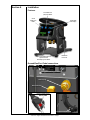
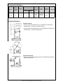
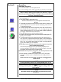
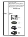
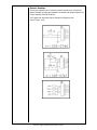
Owner’s Manual
Product:
CobraTurn Digital
Turntable
Manual:
091-0677
Serial:
14050001
Voltage Rating: 120 VAC
Revision:
May 2014 Rev D
Model Number: 127-006
n
ow
Sh
h
wit
tion
op
ble
nta
ur
al t
Table of Contents
Safety Considerations.........................................................................i-iii
Installation................................................................................ Section A
Features..............................................................................................................1
Ground/Gas/Foot Pedal Connection...................................................................1
Technical Specifications......................................................................................2
Dimensions.........................................................................................................3
Operation..................................................................................Section B
Operating Procedure...........................................................................................4
Troubleshooting..................................................................................................5
Accessories..............................................................................Section C
Kits......................................................................................................................5
Remote Hookups................................................................................................6
Appendices...............................................................................Section F
Diagrams / Parts List...........................................................................................7
Mechanical..........................................................................................................8
Electrical........................................................................................................... 11
Safety Warnings
Warranty
THIS PAGE INTENTIONALLY BLANK
SAFETY CONSIDERATIONS
ELECTRIC ARC WELDING EQUIPMENT
CAUTION : READ BEFORE ATTEMPTING INSTALLATION, OPERATION OR
MAINTENANCE OF THIS EQUIPMENT
1-1 INTRODUCTION
This equipment is intended for ultimate
application by commercial/industrial
users and for operation by persons
trained and experienced in the use and
maintenance of welding equipment.
Operation should not be undertaken
without adequate training in the use of
such equipment. Training is available
from many public and private schools or
similar facilities.
Safe practices in the installation, operation and maintenance of this equipment
requires proper training in the art, a
careful study of the information provided
with the equipment, and the use of
common sense. Rules for safe use
are generally provided by suppliers of
welding power sources, compressed
gas suppliers, and electrode suppliers.
Careful compliance with these rules will
promote safe use of this equipment.
The following Safety Rules cover some
of the more generally found situations.
READ THEM CAREFULLY. In case of
any doubt, obtain qualified help before
proceeding.
1-2 GENERAL PRECAUTIONS
A. Burn Prevention
ELECTRIC ARC WELDING PRODUCES
HIGH INTENSITY HEAT AND ULTRAVIOLET RADIANT ENERGY WHICH
MAY CAUSE SERIOUS AND PERMANENT EYE DAMAGE AND WHICH
MAY DAMAGE ANY EXPOSED SKIN
AREAS.
Wear helmet with safety goggles or
glasses with side shields underneath,
appropriate filter lenses or plates (protected by clear cover glass). This is a
must for welding or cutting (and chipping)
to protect the eyes from radiant energy
and flying metal. Replace cover glass
when broken, pitted, or spattered.
Medical first aid and eye treatment. First
aid facilities and a qualified first aid
person should be available for each shift
unless medical facilities are close by for
immediate treatment of flash burns of
the eyes and skin burns.
Wear protective clothing - leather (or
asbestos) gauntlet gloves, hat, and high
safety-toe shoes. Button shirt collar and
pocket flaps, and wear cuffless trousers
to avoid entry of sparks and slag.
Avoid oily or greasy clothing. A spark
may ignite them.
Flammable hair preparations should not
be used by persons intending to weld
or cut.
Hot metal such as electrode stubs and work
pieces should never be handled without
gloves.
Ear plugs should be worn when working
on overhead or in a confined space. A
hard hat should be worn when others work
overhead.
B. Toxic Fume Prevention
WARNING: The use of this product may
result in exposure to chemicals known
to the State of California to cause cancer
and birth defects or other reproductive
harm.
Adequate ventilation. Severe discomfort,
illness or death can result from fumes,
vapors, heat, or oxygen enrichment or
depletion that welding (or cutting) may
produce. Prevent them with adequate
ventilation. NEVER ventilate with oxygen.
Lead-, cadmium-, zinc-, mercury-, beryllium-bearing and similar materials, when
welded or cut, may produce harmful concentrations of toxic fumes. Adequate local
exhaust ventilation must be used, or each
person in the area, as well as the operator,
must wear an air-supplied respirator. For
beryllium, both must be used.
Metals coated with or containing materials
that emit toxic fumes should not be heated
unless coating is removed form the work
surface, the area is well ventilated, or the
operator wears an air-supplied respirator.
Work in a confined space only while it is
being ventilated and, if necessary, while
wearing an air-supplied respirator.
Causes of fire and explosion are: combustibles reached by the arc, flame,
flying sparks, hot slag, or heated material, misuse of compressed gases and
cylinders, and short circuits.
BE AWARE THAT flying sparks or falling
slag can pass through cracks, along
pipes, through windows or doors, and
through wall or floor openings, out of
sight of the goggled operator. Sparks
can fly many feet.
To prevent fires and explosion:
Keep equipment clean and operable,
free of oil, grease, and (in electrical
parts) of metallic particles that can cause
short circuits.
If combustibles are in area, do NOT weld
or cut. Move the work if practicable,
to an area free of combustibles. Avoid
paint spray rooms, dip tanks, storage
areas, ventilators. If the work cannot
be moved, move combustibles at least
35 feet away, out of reach of sparks and
heat; or protect against ignition with
suitable and snug-fitting, fire-resistant
covers or shields.
Walls touching combustibles on opposite
sides should not be welded on (or cut).
Walls, ceilings, and floor near work
should be protected by heat-resistant
covers or shields.
Fire watcher must be standing by with
suitable fire extinguishing equipment
during and for some time after welding
or cutting if:
Gas leaks in a confined space should be
avoided. Leaked gas in large quantities can
change oxygen concentration dangerously.
Do not bring gas cylinders into a confined
space.
1. Appreciable combustibles (including
building construction) are within 35 feet.
Leaving confined space, shut OFF gas
supply at source to prevent possible accumulation of gases in the space if downstream valves have been accidentally
opened or left open. Check to be sure that
the space is safe before reentering it.
3. Openings (concealed or visible) in
floors or walls within 35 feet may expose
combustibles to sparks.
Vapors from chlorinated solvents can be
decomposed by the heat of the arc (or
flame) to form PHOSGENE, a highly toxic
gas, and other lung and eye irritating products. The ultraviolet (radiant) energy of the
arc can also decompose trichloroethylene
and perchloroethylene vapors to form
phosgene. DO NOT WELD or cut where
solvent vapors can be drawn into the
welding or cutting atmosphere or where
the radiant energy can penetrate to atmospheres containing even minute amounts of
trichloroethylene or perchloroethylene.
C. Fire and Explosion Prevention
2. Appreciable combustibles are further
than 35 feet, but can be ignited by
sparks.
4. Combustibles adjacent to walls, ceilings, roofs, or metal partitions can be
ignited by radiant or conducted heat.
Hot work permit should be obtained
before operation to ensure supervisor’s
approval that adequate precautions have
been taken.
After work is done, check that area is
free of sparks, glowing embers, and
flames.
An empty container that held combustibles, or that can produce flammable or
toxic vapors when heated, must never
be welded on or cut, unless container
has first been cleaned in accordance
with industry standards.
This includes: a thorough steam or
caustic cleaning (or a solvent of water
washing, depending on the combustible’s
solubility), followed by purging and inerting with nitrogen or carbon dioxide, and
using protective equipment.
Water-filling just below working level may
substitute for inerting.
A container with unknown contents
should be cleaned (see paragraph
above). Do NOT depend on sense of
smell or sight to determine if it is safe
to weld or cut.
Hollow castings or containers must be
vented before welding or cutting. They
can explode.
Explosive atmospheres. NEVER weld or
cut where the air may contain flammable
dust, gas, or liquid vapors (such as
gasoline).
D. Compressed Gas Equipment
The safe handling of compressed gas
equipment is detailed in numerous
industry publications. The following
general rules cover many of the most
common situations.
1. Pressure Regulators
Regulator relief valve is designed to
protect only the regulator from overpressure; it is not intended to protect
any downstream equipment. Provide
such protection with one or more relief
devices.
Never connect a regulator to a cylinder
containing gas other than that for which
the regulator was designed.
Remove faulty regulator from service
immediately for repair (first close cylinder
valve). The following symptoms indicate
a faulty regulator:
Leaks - if gas leaks externally.
Excessive Creep - if delivery pressure
continues to rise with downstream valve
closed.
Faulty Gauge - if gauge pointer does
not move off stop pin when pressurized,
nor returns to stop pin after pressure
release.
Repair. Do NOT attempt repair. Send
faulty regulators for repair to manufacturer’s designated repair center, where
special techniques and tools are used
by trained personnel.
2. Cylinders
Cylinders must be handled carefully to
prevent leaks and damage to their walls,
valves, or safety devices:
Avoid electrical circuit contact with
cylinders including third rails, electrical
wires, or welding circuits. They can
produced short circuit arcs that may lead
to a serious accident. (See 1-3C)
ICC or DOT marking must be on each
cylinder. It is an assurance of safety
when the cylinder is properly handled.
Identifying gas content. Use only cylinders with name of gas marked on
them; do not rely on color to identify
gas content. Notify supplier if unmarked.
NEVER DEFACE or alter name, number,
or other markings on a cylinder. It is illegal
and hazardous.
Empties: Keep valves closed, replace caps
securely; mark MT; keep them separate
from FULLS, and return promptly.
Prohibited use. Never use a cylinder or its
contents for other than its intended use,
NEVER as a support or roller.
Locate or secure cylinders so they cannot
be knocked over.
Passageways and work areas. Keep cylinders clear of areas where they may be
stuck.
Transporting cylinders. With a crane, use
a secure support such as a platform or
cradle. Do NOT lift cylinders off the ground
by their valves or caps, or by chains, slings,
or magnets.
Do NOT expose cylinders to excessive
heat, sparks, slag, and flame, etc. that may
cause rupture. Do not allow contents to
exceed 55 degrees C (130 degrees F.)
Cool with water spray where such exposure
exists.
Protect cylinders, particularly valves from
bumps, falls, falling objects, and weather.
Replace caps securely when moving cylinders.
Stuck valve. Do NOT use a hammer or
wrench to open a cylinder valve that cannot
be opened by hand. Notify your supplier.
Mixing gases. NEVER try to mix any gases
in a cylinder.
NEVER refill any cylinder.
Cylinder fittings should never be modified
or exchanged.
3. Hose
Prohibited use. Never use hose other
than that designed for the specified gas.
A general hose identification rule is: red
for fuel gas, green for oxygen, and black
for inert gases.
Use ferrules or clamps designed for the
hose (not ordinary wire or other substitute)
as a binding to connect hoses to fittings.
No copper tubing splices. Use only standard brass fittings to splice hose.
away from people and sources of ignition.
Wipe with a clean, lintless cloth.
Match regulator to cylinder. Before
connecting, check that the regulator label
and cylinder marking agree, and that the
regulator inlet and cylinder outlet match.
NEVER Connect a regulator designed
for a particular gas or gases to a cylinder
containing any other gas.
Tighten connections. When assembling
threaded connections, clean and smooth
seats where necessary. Tighten. If
connection leaks, disassemble, clean,
and retighten, using properly fitting
wrench.
Adapters. Use a CGA adapter (available
from your supplier) between cylinder
and regulator, if one is required. Use
two wrenches to tighten adapter marked
RIGHT and LEFT HAND threads.
Regulator outlet (or hose) connections
may be identified by right hand threads
for oxygen and left hand threads (with
grooved hex on nut or shank) for fuel
gas.
5. Pressurizing Steps:
Drain regulator of residual gas through
suitable vent before opening cylinder
(or manifold valve) by turning adjusting
screw in (clockwise). Draining prevents
excessive compression heat at high
pressure seat by allowing seat to open
on pressurization. Leave adjusting
screw engaged slightly on single-stage
regulators.
Stand to side of regulator while opening
cylinder valve.
Open cylinder valve slowly so that regulator pressure increases slowly. When
gauge is pressurized (gauge reaches
regulator maximum) leave cylinder valve
in following position: for oxygen and inert
gases, open fully to seal stem against
possible leak; for fuel gas, open to less
than one turn to permit quick emergency
shut-off.
Use pressure charts (available from
your supplier) for safe and efficient
recommended pressure settings on
regulators.
Avoid long runs to prevent kinks and abuse.
Suspend hose off ground to keep it from
being run over, stepped on, or otherwise
damaged.
Check for leaks on first pressurization
and regularly thereafter. Brush with
soap solution. Bubbles indicate leaks.
Clean off soapy water after test; dried
soap is combustible.
Coil excess hose to prevent kinks and
tangles.
E. User Responsibilities
Protect hose from damage by sharp edges,
and by sparks, slag, and open flame.
Remove leaky or defective equipment
from service immediately for repair. Read
and follow user manual instructions.
Examine hose regularly for leaks, wear, and
loose connections. Immerse pressured
hose in water; bubbles indicate leaks
Repair leaky or worn hose by cutting area
out and splicing. Do NOT use tape.
4. Proper Connections
Clean cylinder valve outlet of impurities that
may clog orifices and damage seats before
connecting regulator. Except for hydrogen,
crack valve momentarily, pointing outlet
Follow all Safety Rules.
F. Leaving Equipment Unattended
Close gas supply at source and drain
gas.
G. Rope Staging-Support
Rope staging-support should not be
used for welding or cutting operation;
rope may burn.
1-3 ARC WELDING
Comply with precautions in 1-1, 1-2,
and this section. Arc Welding, properly
done, is a safe process, but a careless
operator invites trouble. The equipment
carries high currents at significant voltages. The arc is very bright and hot.
Sparks fly, fumes rise, ultraviolet and
infrared energy radiates, weldments
are hot, and compressed gases may
be used. The wise operator avoids
unnecessary risks and protects himself
and others from accidents.
A. Burn Protection
Comply with precautions in 1-2.
The welding arc is intense and visibly
bright. Its radiation can damage eyes,
penetrate lightweight clothing, reflect
from light-colored surfaces, and burn
the skin and eyes. Skin burns resemble
acute sunburn; those from gas-shielded
arcs are more severe and painful. DON’T
GET BURNED; COMPLY WITH PRECAUTIONS.
1. Protective Clothing
Wear long-sleeve clothing in addition to
gloves, hat, and shoes. As necessary,
use additional protective clothing such
as leather jacket or sleeves, flameproof
apron, and fire-resistant leggings. Avoid
outer garments of untreated cotton.
Bare skin protection. Wear dark, substantial clothing. Button collar to protect
chest and neck, and button pockets to
prevent entry of sparks.
2. Eye and Head Protection
Protect eyes from exposure to arc. Eyes
may be damaged by radiant energy
when exposed to the electric arc, even
when not looking in the direction of the
arc. Never look at an electric arc without
protection.
Welding helmet or shield containing a
filter plate shade no. 12 or denser must
be used when welding. Place over face
before striking arc.
Protect filter plate with a clear cover
plate.
Cracked or broken helmet or shield
should NOT be worn; radiation can be
passed through to cause burns.
Cracked, broken, or loose filter plates
must be replaced IMMEDIATELY.
Replace clear cover plate when broken,
pitted, or spattered.
Flash goggles with side shields MUST
be worn under the helmet to give some
protection to the eyes should the helmet
not be lowered over the face before
an arc is struck. Looking at an arc
momentarily with unprotected eyes
(particularly a high intensity gas-shielded
arc) can cause a retinal burn that may
leave a permanent dark area in the field
of vision.
3. Protection of Nearby Personnel
Enclose the welding area. For production
welding, a separate room or enclosed
bay is best. In open areas, surround the
operation with low-reflective, noncombustible screens or panels. Allow for free air
circulation, particularly at floor level.
Viewing the weld. Provide face shields for
all persons who will be looking directly
at the weld.
Others working in area. See that all persons
are wearing flash goggles.
Before starting to weld, make sure that
screen flaps or bay doors are closed.
B. Toxic Fume Prevention
Comply with precautions in 1-2B.
Generator engine exhaust must be vented
to the outside air. Carbon monoxide can
kill.
C. Fire and Explosion Prevention
Comply with precautions in 1-2C.
Equipment’s rated capacity. Do not overload
arc welding equipment. It may overheat
cables and cause a fire.
Loose cable connections may overheat or
flash and cause afire.
Never strike an arc on a cylinder or other
pressure vessel. It creates a brittle area that
can cause a violent rupture or lead to such
a rupture later under rough handling.
D. Compressed Gas Equipment
Comply with precautions in 1-2D.
E. Shock Prevention
Exposed electrically hot conductors or
other bare metal in the welding circuit, or in
ungrounded, electrically-HOT
ous condition that can shock, possibly
fatally.
Before welding, check ground for continuity. Be sure conductors are touching
bare metal of equipment frames at connections.
If a line cord with a ground lead is
provided with the equipment for connection to a switch box, connect the ground
lead to the grounded switch box. If a
three-prong plug is added for connection
to a grounded mating receptacle, the
ground lead must be connected to the
ground prong only. If the line cord comes
with a three-prong plug, connect to a
grounded mating receptacle. Never
remove the ground prong from a plug, or
use a plug with a broken ground prong.
2. Connectors
Fully insulated lock-type connectors
should be used to join welding cable
lengths.
3. Cables
Frequently inspect cables for wear,
cracks, and damage. IMMEDIATELY
REPLACE those with excessively worn
or damaged insulation to avoid possibly
lethal shock from bared cable. Cables
with damaged areas may be taped to
give resistance equivalent to original
cable.
Keep cable dry, free of oil and grease,
and protected from hot metal and
sparks.
equipment can fatally shock a person
whose body becomes a conductor. DO
NOT STAND, SIT, LIE, LEAN ON, OR
TOUCH a wet surface when welding without
suitable protection.
4. Terminals and Other Exposed
Parts
Terminals and other exposed parts of
electrical units should have insulating
covers secured before operation.
To protect against shock:
5. Electrode Wire
Electrode wire becomes electrically HOT
when the power switch of gas metal-arc
welding equipment is ON and welding
gun trigger is pressed. Keep hands
and body clear of wire and other HOT
parts.
Keep body and clothing dry. Never work
in damp area without adequate insulation
against electrical shock. Stay on a dry
duckboard, or rubber mat when dampness
or sweat cannot be avoided. Sweat, sea
water, or moisture between body and
an electrically HOT part - or grounded
metal - reduces the body surface electrical resistance, enabling dangerous and
possibly lethal currents to flow through
the body.
1. Grounding the Equipment
When installing, connect the frames of
each unit such as welding power source,
control, work table, and water circulator to
the building ground. Conductors must be
adequate to carry ground currents safely.
Equipment made electrically HOT by stray
currents may shock, possibly fatally. Do
NOT GROUND to electrical conduit, or to
a pipe carrying ANY gas or a flammable
liquid such as oil or fuel.
Three-phase connection. Check phase
requirement of equipment before installing.
If only three-phase power is available,
connect single-phase equipment to only
two wires of the three-phase line. Do NOT
connect the equipment ground lead to
the third (live) wire, or the equipment
will become electrically HOT - a danger-
6. Safety Devices
Safety devices such as interlocks and
circuit breakers should not be disconnected or shunted out.
Before installation, inspection, or service
of equipment, shut OFF all power, and
remove line fuses (or lock or red-tag
switches) to prevent accidental turning
ON of power. Disconnect all cables from
welding power source, and pull all 115
volts line-cord plugs.
Do not open power circuit or change
polarity while welding. If, in an emergency, it must be disconnected, guard
against shock burns or flash from switch
arcing.
Leaving equipment unattended. Always
shut OFF, and disconnect all power to
equipment.
Power disconnect switch must be available near the welding power source.
Thank You
For selecting a quality product. We want you to take
pride in operating this product...as much pride as we
have in bringing the product to you!
Please Examine Carton and Equipment For Damage Immediately
When this equipment is shipped, title passes to the purchaser upon receipt by the
carrier. Consequently, claims for material damaged in shipment must be made by the
purchaser against the transportation company at the time the shipment is received.
Please record your equipment identification information below for future reference. This
information can be found on your machine nameplate.
Model Name & Number
_____________________
Code & Serial Number
_____________________
Date of Purchase
_____________________
Whenever you request replacements parts for, or information on this equipment always
supply the information you have recorded above.
Read this Owner’s Manual completely before attempting to use this equipment. Save this manual
and keep it handy for quick reference. Pay particular attention to the safety instructions we
have provided for your protection.
Section A Installation
Features
Forward/Reverse
(DIR) Push Button
On/Off
(PWR) Push
Button
Digital RPM
LED Display
Tilt Release/
Push Knob
Speed Control/LED Brightness
Adjustment Knob
Start/Stop/Jog Push Button
Ground/Gas/Foot Pedal connections
Foot Pedal/Remote Connector
Ground Lug
Gas Connector
Fuse in Power Cord
P/N 151-0050
Tilt Release/Push Knob
CobraTurn™ Digital Turntable Owner's Manual - Page 1
Technical Specifications
Model
127-006
Optional
Turntable
Diameter
10"
Degrees
Tilt
0° to 90°
Speed Range R.P.M.
Low
.3
High
10
Ground
Capacity
AMPS
Input
Voltage
400A
60%
Duty
Cycle
120VAC
50/60 Hz
Shipping
Transmission
Weight
32 lbs
Gear
Load Specifications
Turntable Vertical
• 300 lbs. in the vertical position from 1-4 RPM with a balanced &
centered load, 5” max from the table surface
• 150 lbs. in the vertical position from 0.3-10 RPM with a balanced &
centered load, 7” max from table surface
Turntable Horizontal
• 300 lbs. in the horizontal position from 0.3-10 RPM with a balanced
load & centered load
CobraTurn™ Digital Turntable Owner's Manual - Page 2
Dimensions
CobraTurn™ Digital Turntable Owner's Manual - Page 3
Section B Operation
Operating Procedure
1. Connect turntable to 120 VAC power source.
2. Connect welding ground cable to grounding lug assembly on turntable.
NOTE:
Failure to attach a welding ground cable to the CobraTurn™ Digital
Turntable grounding lug will result in damage to the turntable electrical
circuit and void unit's warranty.
3. Connect foot switch/pedal if required, "PdL" will be briefly displayed (see
picture on page 1).
PWR Button
4. Push PWR button to switch the unit on.
NOTE: If unit doesn't turn on, check power connection and
the fuse.
5. The display will briefly show the firmware version and then show the last
rotational speed used. If you see any other message, please see the
Troubleshooting section.
DIR Button
6. To adjust display and indicators' brightness press and hold DIR button
(the turntable must be stopped). After ~1 sec., the display changes and
shows the brightness value (1 to 63), rotate knob to adjust brightness of
the display. Release DIR button when done.
7. Push DIR push button to desired rotation direction.
8. Establish desired speed setting using the knob while reading the LED
display on the turntable.
Knob Button
9. To start turntable with the set speed press knob and release within 1
sec., the motor will start and the knob lights green. Press knob again to
stop and the knob flashes red then turns blue. If the knob is held longer
than 1 sec., the turntable starts jogging (10 RPM), knob lights blinking
green and turntable jogs until released.
NOTE: When knob is pressed, the knob rotation is ignored to prevent
value changes while pressing.
With the foot pedal plugged in, the speed setting displayed is the
maximum speed the foot pedal will use. While pressing the foot pedal,
the display shows speed of the foot pedal setting.
NOTE: When the foot pedal is plugged in, the Start/Stop function of the
knob is disabled.
10.Press and hold the PWR button (display shows “OFF”) until power
is turned to standby mode. If released sooner, the display returns to
normal.
NOTE: The unit is not completely off unless it is unplugged from
power source.
NOTE:
Pressing invalid key causes "Err" message displayed for ~2 sec.
NOTE:
Pressing invalid key while foot pedal is plugged in, displays "PdL" and
key is ignored.
NOTE:
All turntable settings and calibration are preserved when power
is turned off.
CobraTurn™ Digital Turntable Owner's Manual - Page 4
Additional Display Messages
• nEE: This means the turntable memory was not set or lost. Power cord
needs to be unplugged to reset. If this error persists, please contact MK
support.
• bAd: This message is displayed for about 3 seconds and default settings
are restored and self-testing continues. WARNING: The turntable SHOULD
be recalibrated.
• CAL: If the display shows "CAL", the hardware calibration needs to be
performed (never calibrated or corrupted).
NOTE: Calibration requires special setup.
Contact MK Products for details.
Section C Accessories
Kits
005-0040
3-Jaw Chuck
(optional)
005-0677
10" Turntable
(optional)
005-0747
On/Off Foot Switch
(standard)
005-0746
Heavy Duty
Variable Speed Foot Control
(optional)
CobraTurn™ Digital Turntable Owner's Manual - Page 5
Remote Hookups
This section explains how to interface external controls to the CobraTurn™
Digital Turntable including the standard Foot Switch and Variable Speed Foot
Control available from MK Products.
The Trigger and Jog inputs may be Switches or Signals Levels.
(low=0v high= 3.3V)
CobraTurn™ Digital Turntable Owner's Manual - Page 6
Appendices
Diagrams / Parts List
Turntable Assembly..................................................................... 8
Housing Assembly..................................................................... 10
Electrical.................................................................................... 11
CobraTurn™ Digital Turntable Owner's Manual - Page 7
CobraTurn Digital Turntable Assembly
CobraTurn™ Digital Turntable Owner's Manual - Page 8
CobraTurn™ Digital Turntable Owner's Manual - Page 9
1
2
3
4
5
6
7
8
9
10
11
12
13
14
15
16
17
18
19
1
1
1
1
1
1
1
1
1
1
1
2
1
2
1
10
2
1
4
No. Qty.
003-2498
003-2499
003-2500
003-2501
003-2504
005-0777
145-0041
153-0909
261-0167
303-0110
309-0006
313-0013
313-0136
315-0030
319-0022
320-0095
320-0127
321-1111
328-0047
Part No.
ASSY BASE TURNTABLE
ASSY MOTOR TURNTABLE
ASSY HOUSING TURNTABLE
ASSY FRONT PNL ELEC BOX TURNTABLE
ASSY KNOB TURNTABLE
ASSY PCB FR PNL CNTLR TURNTABLE
BEZEL SNAP-IN BLACK
CON HSG CRMP 3T .156 .04
SLEEVE HANDLE TURNTABLE
ORING 13/16 ID x 15/16 OD
GASKET RUBBER
E-RING 3/4ID
RING EXT 13/16" ID
BRG SLV THRUST 3/4ID X 1-1/4OD X 1/16LG
SCR FHSC 10-24X1/2 ST BLK OXIDE
SCR BHSC 8-32X1/4 ST BLK ZINC
SCR BHSC 10-24X1/2 ST BLK ZINC
SSCR CONE 1/4-20X3/8 SS
SCR SHC 10-32 X 5/8
Description
20
21
22
23
24
25
26
27
28
29
30
31
32
33
34
35
36
37
38
1
4
1
6
3
1
4
1
2
1
1
1
1
1
1
1
A/R
A/R
1
Front Body Assembly
331-0119
333-0007
333-0041
333-0044
336-0105
336-0108
336-0130
351-0266
405-1363
419-0130
431-2055
431-2060
431-2064
431-2065
431-2072
438-0088
823-0050
835-0018
843-0712
WSHR SS .540 ID x .75 OD x .02 THK
WSHR SPR LK #10
WSHR LK #4 INTL STAR STL
WSHR LK #8 INTL STAR STL
SCR PN P 4-40X3/16 SS
SCR PN P 4-40X3/8 SS
SCR PN P 8-32X3/8 SS
STRAIN RELIEF 90 DEG
LABEL TURNTABLE
SPR COMP
WASHER TURNTABLE
HANDLE TURNTABLE
SHAFT AXLE TURNTABLE
KNOB PUSH TURNTABLE
PLUNGER LOCK TURNTABLE
PAINT PANEL BACK TURNTABLE
LOCTITE 222 PURPLE
GREASE RENOLT G193
ASSY POWER CABLE
CobraTurn Digital Turntable Housing Assembly
APPLY ADH LOCTITE
222 PURPLE - LOW STR
APPLY COMPOUND
JOINT NOALOX
APPLY O-RING
SILICONE
LUBRICANT
APPLY GREASE RENOLIT G193
APPLY LOCTITE,
PST PIPE
SEALANT
APPLY O-RING
SILICONE
LUBRICANT
No. Qty
1
2
3
4
5
6
7
8
9
10
11
12
13
14
15
16
17
18
19
20
1
1
2
1
2
1
1
1
1
Housing Turntable Assembly
Part
003-2503
316-0026
331-0188
333-0013
341-0106
431-2039
431-2057
431-2061
716-0009
Description
ASSY GROUND CABLE
Not available separately
Not available separately
Not available separately
Not available separately
SCR TR P 8-32X1/4 SST
WSHR FL 0.525ID X 0.875ODX0.063T Brass
WSHR SPR LK #1/2
NUT HX 1/2-13UNC 5/16THK BRS
Not available separately
Not available separately
Not available separately
GAS FITTING RIGHT ANGLE
WASHER INSUL GROUND
COPPER BRUSH TURNTABLE
Not available separately
Not available separately
Not available separately
Not available separately
DISC WIRE CLOTH SS 0.5 OD
CobraTurn™ Digital Turntable Owner's Manual - Page 10
CobraTurn Digital Turntable Electrical
CobraTurn™ Digital Turntable Owner's Manual - Page 11
16882 Armstrong Ave.
Irvine, CA 92606
Tel (949)863-1234
Fax (949)474-1428
www.mkproducts.com
August 1, 2010
THIS PAGE INTENTIONALLY BLANK
16882 Armstrong Ave.
Irvine, CA 92606
Tel (949)863-1234 Fax (949)474-1428
www.mkproducts.com