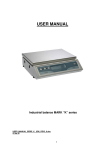
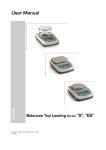
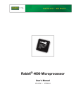
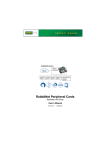
1
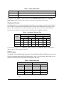
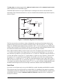
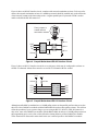
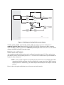
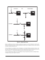
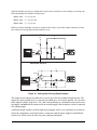
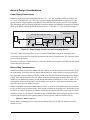
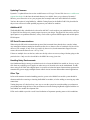
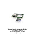
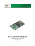
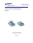
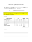
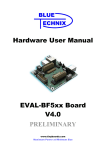
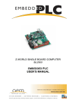
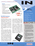
TN250 Designing With a RabbitCore® Module Introduction RabbitCore modules are designed to mount directly on a motherboard of your own design for quick integration into your embedded application. The RabbitCore modules already have the integrated and tested microprocessor, memory, and networking interfaces you need to allow you to focus on developing your application. RabbitCore modules typically have some or all of these features. • Rabbit® microprocessor with four to six serial ports • SRAM • Flash memory • Serial or NAND flash mass storage memory • Removable mass storage memory cards • A/D converter • Onboard power supply and voltage regulators • Ethernet interface • Wireless interface — Wi-Fi® or ZigBee® Once you’re ready to begin developing your own application, you will need to select the RabbitCore module that has the basic features you need. Our Web site provides a RabbitCore Module Selection Guide to help you select the RabbitCore module that has exactly the features you need to support your application. Also check the www.rabbit.com/products/CoreModules/ page for a more complete list that includes the newest releases. All RabbitCore modules, except the RCM3400, have an onboard programming header. The Prototyping Boards for the RabbitCore modules based on the Rabbit 3000 may also be hooked up with Rabbit Semiconductor’s LCD/keypad module. Each series of RabbitCore modules has a Development Kit that includes a Prototyping Board and the complete Dynamic C software package of sample programs and libraries that show you how to use the many features of the rabbitCore module you have selected. This allows you to quickly port your design as it evolves from the Prototyping Board to your very own motherboard. There is a convenient implementation of the RabbitCore module plus motherboard design in Rabbit Semiconductor’s RabbitFLEX™ configurable single-board computer solution. RabbitFLEX is based on a PowerCore FLEX module used with a motherboard whose design you can complete with an easy-to-use online configurator on Rabbit Semiconductor’s Web site. Your unique design can then be scheduled and built for fast turnaround at Rabbit Semiconductor’s factory in the United States. 022-0118 Rev. A 1 This technical note is not intended to be an exhaustive tutorial on electrical engineering design principles since many excellent references cover these topics in complete detail. Rather, this technical note elaborates some of the more important design considerations for a design built around a RabbitCore module, and provides some simple circuit schematics based on the Prototyping Boards sold with various RabbitCore modules to illustrate some basic inexpensive ways to implement certain types of circuit. Refer to your favorite electrical engineering and PCB layout textbooks for additional, more complete information. Design Sequence Once you have selected the RabbitCore module that has the basic features you’re looking for, you’re ready to begin your design. Start assigning the I/O with features that are available only on certain pins, then use features that are more generally available, and finally using any remaining pins for general-purpose I/O. These features are generally associated with Parallel Ports A–E on the Rabbit microprocessor (the Rabbit 3000 has Parallel Ports A–G). Where appropriate, each feature will have a suggested interface circuit and a description of it, and some features will have references to Dynamic C sample programs that illustrate their use. Note that not all the parallel port pins are necessarily available on a given RabbitCore module. Regardless of what type of non-serial input you will be using on any of the RabbitCore modules, the input should be pulled up (or down)—floating inputs tend to draw considerably more current and will be unprotected. Figure 1 shows an example of an input that is pulled up. R1 is a pullup resistor, and R2 is a current-limiting resistor. Resistors in the range of 10 kΩ to 100 kΩ are normally used for these two resistors. The section on Digital Inputs and Outputs shows inputs pulled down to ground, and shows other signal-conditioning circuits to filter or clamp the input signal presented to the Rabbit microprocessor input. Vcc R1 ® R2 Figure 1. Pulled-Up Input Input Capture The input capture peripheral on the Rabbit 3000 and the Rabbit 4000 chips consists of two channels, each of which contains a 16-bit counter and edge-detection circuitry. The input capture channels are usually used to determine the time between events. An event is signaled by a rising or falling edge (or optionally by either edge) on one of 12 or 16 input pins that can be selected as the input for either of the two channels. Each input-capture channel can accept input from one of the parallel port pins listed in Table 1. Remember that you can choose up to two input-capture channels. Use ICTxR to select which input pins to trigger on. 022-0118 Rev. A duration rising edge falling edge Figure 2. Captured Digital Signal 2 Table 1. Input Capture Pins Microprocessor Pins With Input Capture Capability Rabbit 3000 PC1, PC3, PC5, PC7, PD1, PD3, PD5, PD7, PF1, PF3, PF5, PF7, PG1, PG3, PG5, PG7 Rabbit 4000 PC1, PC3, PC5, PC7, PD1, PD3, PD5, PD7, PE1, PE3, PE5, PE7 The Dynamic C IC_TEST.C sample programs in the SAMPLES\Rabbit3000 or the SAMPLES\ Rabbit4000 folders illustrate how to measure a duration using an input capture input. Quadrature Decoder The Rabbit 4000 has a two-channel Quadrature Decoder that accepts inputs via specific pins on Parallel Ports D and E to detect movement and the direction of movement. Each channel has two inputs, the inphase (I) input and the 90 degree or quadrature-phase (Q) input. Table 2 lists the possible Quadrature Decoder pins for RabbitCore modules based on the Rabbit 3000 and Rabbit 4000 chips. Table 2. Quadrature Decoder Pins Rabbit 3000 Inputs Channel 1 Rabbit 4000 Channel 2 Channel 1 Channel 2 I Q I Q I Q I Q Option 1 PF1 PF0 PF3 PF2 PD1 PD0 PD3 PD2 Option 2 PF5 PF4 PF7 PF6 PE1 PE0 PE3 PE2 Option 3 — — — — PE5 PE4 PE7 PE6 Several sample programs in the SAMPLES\Rabbit3000 and the SAMPLES\Rabbit4000 folders illustrate the use of the Quadrature Decoder. PWM Outputs The Rabbit 3000 and Rabbit 4000 chips have a Pulse Width Modulator (PWM) that consists of a 10-bit free running counter and four width registers. Table 3 lists the possible PWM output pins for RabbitCore modules based on the Rabbit 3000 and Rabbit 4000 chips Table 3. PWM Output Pins Rabbit 3000* Rabbit 4000 PWM Output Pins PWM Output Pins Channel 0 PF4, PG3 Channel 0 PC4, PD4, PE4 Channel 1 PF5, PG7 Channel 1 PC5, PD5, PE5 Channel 2 PF6, PD5 Channel 2 PC6, PD6, PE6 Channel 3 PF7, PD7 Channel 3 PC7, PD7, PE7 * Parallel Port D/G options introduced with Rev. A of the Rabbit 3000 chip. 022-0118 Rev. A 3 The PWM_TEST.C sample programs in the SAMPLES\Rabbit3000 and the SAMPLES\Rabbit4000 folders illustrate the use of the PWM outputs. The Rabbit 2000 can also be set up for PWM outputs even though it does not have the built-in PWM functionality. This is demonstrated in the D/A converter of the BL1800 (Jackrabbit) single-board computers, shown in Figure 3. 24.9 kW DA0 8 9 + 10 LM324 1.0 kW 24.9 kW 100 nF PF6 10 kW 24.9 kW DA1 14 1.0 kW 13 + 12 LM324 24.9 kW 100 nF PF7 10 kW Figure 3. Schematic Diagram of D/A Converters The D/A converters have no reference voltage. Although they may have good resolution from one programmed voltage to the next, they do not have absolute accuracy. This is because the +3.3 V supply can change ±5%, the PWM outputs might not achieve the full 0 V and 3.3 V rail out of the processor, and the gain resistors in the circuit have a 1% tolerance. The D/A converters therefore need individual calibration, with the calibration constants held in software before absolute accuracy can be relied on. Pulse-width modulation (PWM) is used for the D/A conversion. The digital signal, which is either 0 V or 3.3 V, will be a train of pulses. The voltage will be 0 V for a given time, then jump to 3.3 V for a given time, then back to ground for a given time, then back to 3.3 V, and so on. A hardware filter that consists of a resistor and capacitor averages the 3.3 V signal and the 0 V signal over time. Therefore, if the time that the signal is at 3.3 V is equal to the time the signal is 0 V, the duty cycle will be 50%, and the average signal will be 1.65 V. If the time at 3.3 V is only 25% of the time, then the average voltage will be 0.825 V. Thus, the software needs to only vary the time the signal is at 3.3 V with respect to the time the signal is at 0 V to achieve any desired voltage between 0 and 3.3 V. It is very easy to do pulse-width modulation with the Rabbit 3000 microprocessor because the chip’s architecture includes an advanced PWM feature. Serial Ports Up to four or six serial ports may be set up with a RabbitCore module, depending on the RabbitCore module. The serial ports may be set up for RS-485 or for RS-422/RS-232, depending on the transceivers and associated hardware used on the motherboard. The sample program libraries for the RabbitCore modules based on the Rabbit 3000 (for example, SAMPLES\RCM3300\RCM33xx.LIB) show how to configure the serial ports in software. 022-0118 Rev. A 4 Figure 4 shows an RS-485 interface circuit, complete with network termination resistors. For best performance, the network termination resistors in a multidrop network should be enabled only on the end nodes of the network, but not on the intervening nodes. A regular parallel port I/O pin such as PD0 is used to enable or disable the RS-485 transceiver. Place jumpers to enable network termination resistors 2 1 4 3 6 5 +3.3 V 485 681 W 1 RxE PD0 TxE 3 4 100 kW RO 6 2 1 7 6 5 DE DI 220 W 681 W SP3483CN 485+ Figure 4. Sample Motherboard RS-485 Interface Circuit Figure 5 shows an RS-232 interface circuit for two serial ports, which may be configured in software as two RS-232 channels without flow control or as one RS-232 channel with flow control. +3.3 V 100 kW PC3 PC2 PC0 PC1 +3.3 V 100 kW 9 R2IN 8 7 10 T2OUT T2IN 14 11 T1OUT T1IN 13 12 R1IN R1OUT R2OUT RxC TxC TxD RxD SP3232EB Figure 5. Sample Motherboard RS-232 Interface Circuit Although most RabbitCore modules have a 100 kΩ pullup resistor on the parallel port lines that are used as the receive lines, RabbitCore modules with the Rabbit 4000 do not have these pullup resistors. This will not affect the operation of your system as long as you are using an RS-232, RS-422, or RS-485 transceiver chip. Also, some of the RabbitCore modules with the Rabbit 4000 do not have a 100 kΩ pullup resistor on the programming port’s receive line, which affects the cloning behavior of those RabbitCore modules. These situations are discussed in more detail in the user’s manual specific to the RabbitCore module. 022-0118 Rev. A 5 When using the RabbitCore modules based on the Rabbit 4000, keep in mind that Serial Ports E and F will not be the default configurations for the parallel port pins they are using. See the user’s manual specific to the RabbitCore module for information on how to configure that module’s parallel port pins. The serial ports may be set up as SDLC/HDLC serial ports, as SPI/clocked serial ports, or as asynchronous serial ports, with the specific pins and options dependent on the Rabbit microprocessor driving the RabbitCore module. These options are discussed below. SDLC/HDLC Serial Ports RabbitCore modules support the Synchronous Data Link Control (SDLC) and the High-Level Data Link Control (HDLC) protocols via synchronous Serial Ports E and F of the Rabbit 3000 and Rabbit 4000 microprocessors. The serial ports share the parallel port pins, which should then be used only with a serial device unless a buffer is added to switch between serial and parallel devices. Table 4. Common SDLC/HDLC Serial Ports Rabbit 3000 Rabbit 4000 Serial Port Tx/Rx Lines Clock Lines Tx/Rx Lines Clock Lines TxE PG6 PG4 PD6, PE6, PC6 PD4, PE4, PC4 RxE PG7 PG5 PD7, PE7, PC7 PD5, PE5, PC5 TxF PG2 PG0 PD2, PE2, PC2 PD0, PE0, PC0 RxF PG3 PG1 PD3, PE3, PC3 PD1, PE1, PC1 Serial Port E Serial Port F The HDLC_TEST.C sample program in the SAMPLES\Rabbit3000 folder demonstrates a simple loopback test using Serial Ports E and F in the HDLC mode. SPI/Clocked Serial Ports Serial Ports A–D (RabbitCore modules with Rabbit 3000 and Rabbit 4000 microprocessors) and Serial Ports A–B (RabbitCore modules with Rabbit 2000 microprocessors) may be used as Serial Peripheral Interface (SPI) or clocked (synchronous) serial ports. Alternative parallel port pins may be configured for these serial ports as explained in the individual RabbitCore user’s manuals. Table 5. Common SPI/Clocked Serial Ports Rabbit 2000 Rabbit 3000 Rabbit 4000 Serial Port Tx/Rx Lines Clock Lines Tx/Rx Lines Clock Lines Tx/Rx Lines Clock Lines Serial Port A PC6/PC7 PB1 PC6/PC7 PB1 PC6/PC7 PB1 Serial Port B PC4/PC5 PB0 PC4/PC5 PB0 PC4/PC5 PB0 Serial Port C PC2/PC3 PC2/PC3 PF1 PC2/PC3 PD2* PC0/PC1 PF0 PC0/PC1 PD0* Asynchronous Serial Port D PC0/PC1 * Note that PD2 and PD0 provide the SCLKC and SCLKD outputs automatically when Serial Ports C and D are set up as clocked serial ports, except for the RCM4000, where Parallel Port D is used for the 16-bit memory bus. Refer to the RCM4000 User’s Manual for other clock output alternatives. 022-0118 Rev. A 6 Asynchronous Serial Ports Any serial port may be used simply as an asynchronous serial port, and may be used as a CMOS serial port or teamed up with an RS-232 or RS-485 transceiver. Dynamic C has many sample programs tailored with a sample library for each RabbitCore module to illustrate their use with the Prototyping Board specific to a particular RabbitCore module. Slave Port A parallel communication port can be set up on the RabbitCore modules as a slave port to communicate with an external master device. More information is available in the microprocessor user’s manual for the Rabbit microprocessor in a particular RabbitCore module. Ethernet Selected RabbitCore modules have onboard Ethernet capability, either 10Base-T or 10/100Base-T. As illustrated by the RCM3400 and its Prototyping Board, it is also possible to add the Ethernet functionality on your motherboard. The Ethernet interface on RabbitCore modules based on the Rabbit 4000 microprocessor is simpler than on the other RabbitCore modules because of the built-in 10Base-T Ethernet capabilities of the microprocessor, which frees up some parallel port pins for other use. Wireless Interface Rabbit Semiconductor’s Technical Note TN249, Designing with Wireless Rabbits, provides design information for using RabbitCore modules with onboard Wi-Fi or ZigBee capabilities. Analog Inputs and Outputs Selected RabbitCore modules have an onboard A/D converter, the ADS7870 chip, that is accessed via clocked Serial Port B. The analog inputs on these RabbitCore modules come out as part of the standard pinout. It is also possible to add the A/D converter functionality on your motherboard either with an A/D converter chip such as the ADS7870 or with op-amps as shown in Figure 6 (the op-amp based A/D converter shown has limited accuracy, but is inexpensive; an A/D converter chip is recommended for better performance). The A/D converter based on the LM324 op-amps compares the DA0 voltage to AD0, the voltage presented to the A/D converter. DA0 therefore cannot be used for the D/A converter when the A/D converter is being used. +3.3 V 24.9 kW AD0 2 100 W 3 100 nF DA0 10 kW 6 100 W 5 24.9 kW DA0 too low LM324 8 10 kW + LM324 + 14 10 kW PB2 PB3 DA0 too high Figure 6. Discrete Inexpensive Op-Amp Based A/D Converter 022-0118 Rev. A 7 The A/D converter programs DA0 using a successive-approximation binary search until DA0 equals the A/D converter input voltage. That programmed DA0 voltage can then be reported as the A/D converter value. The AD0.C sample program in the SAMPLES\BL2500\ADC folder demonstrates this A/D conversion. Use a resistor divider such as the one shown in Figure 7 for the analog inputs. R11 Analog Inputs LN0 ADC LN1 ADC R12 C Analog Ground C R1 R2 AGND Figure 7. Resistor Divider Network to Filter and Scale Analog Inputs R1 and R2 are typically 20 kΩ to 100 kΩ, with a lower resistance leading to more accuracy, but at the expense of a higher current draw. R11 and R12 would then be 180 kΩ to 900 kΩ for a 10:1 attenuator. The capacitor filters noise pulses on the A/D converter input. The actual voltage range for a signal going to the A/D converter input is also affected by the 1, 2, 4, 5. 8, 10, 16, and 20 V/V software-programmable gains available on each channel of the ADS7870 A/D converter chip. Thus, you must scale the analog signal with an attenuator circuit and a software-programmable gain so that the actual input presented to the A/D converter is within the range limits of the ADS7870 A/D converter chip (-2 V to + 2 V or 0 V to + 2 V). The A/D converter chip can only accept positive voltages. With resistors R1 and R2 connected to ground, your analog circuit is well-suited to perform positive A/D conversions. When R1 and R2 are tied to ground for differential measurements, both differential inputs must be referenced to analog ground, and both inputs must be positive with respect to analog ground. The sample programs for specific RabbitCore modules illustrate the use of the onboard A/D converter. It is also possible to add D/A converter functionality on your motherboard either with a D/A converter chip such as the TLV5630 or with LM324 op-amps as shown in Figure 3 in the discussion on PWM outputs. When you use a D/A converter chip, you would buffer and scale the D/A converter outputs. Figure 8 shows the buffering and scaling to provide an output from 0 V to +10 V (12-bit resolution) or ±10 V (11-bit resolution, one bit used for polarity). 022-0118 Rev. A 8 52.3 kW 10 kW DAC 1.667 V ref. 11 kW 133 kW AV0 LM324 11 kW AI0 LM324 2.5 V ref. 133 kW Voltage Outputs AV1 AI1 Current Outputs 11 kW AGND Figure 8. Buffering and Scaling D/A Converter Outputs The DAC_VOLT_ASYNC.C and the DAC_VOLT_SYNC.C sample programs in the Dynamic C SAMPLES\BL2600\DAC folder show how to use the TLV5630 D/A converter to produce an analog output. The DAC.C sample program in the SAMPLES\BL2500\DAC folder shows how to use the LM324 op-amps with PWM to produce an analog output. Digital Inputs and Outputs Any remaining unused parallel port pins can be configured as general-purpose I/O. There may be other pins that may also be used as general-purpose I/O — refer to the user’s manual for the specific RabbitCore module for more information. NOTE: Even if you do not plan to use a parallel port pin, do not leave it as a floating input. These unused pins should be pulled up or down to minimize the current draw by the CMOS circuits in the microprocessor. Alternatively, you could configure the unused pins as an output to avoid the problem. Figure 9 shows the signal-conditioning circuit elements you should consider. 022-0118 Rev. A 9 Vcc OR PULLED UP PULLED DOWN R1 ® R2 ® R2 R1 Vcc R1 ® R2 FILTERING C1 Vcc Vcc D1 R1 CLAMPING ® R2 D2 Figure 9. Digital Input Setup Pullup or pulldown resistors are needed on parallel port input pins to set their default state, which would otherwise be undefined until the software initialization on power-up is completed. Resistors in the range of 10 kΩ to 100 kΩ are normally used. If you are going to be operating in a noisy environment, you can add a filtering capacitor as shown, with the value of the capacitor based on the desired RC time constant between the current-limiting resistor, R2, and the capacitor, C1. The filtering arrangement shown attenuates high-frequency noise. You may add diodes D1 and D2 to provide additional voltage clampdown protection to the digital input when high-voltage spikes might be expected. 022-0118 Rev. A 10 When the Parallel port pins are configured for outputs, they already have certain sinking or sourcing capabilities depending on the Rabbit microprocessor. • Rabbit 2000 — 5.0 V @ 8 mA • Rabbit 3000 — 3.3 V @ 6.8 mA • Rabbit 4000 — 3.3 V @ 8 mA Different voltages and higher currents are usually needed. Figure 10 provides sample schematics to show how sinking or sourcing digital outputs might be set up. SINKING OUTPUT K Vcc 27 kW ® 1 kW 10 nF MMBT2222A SOURCING OUTPUT K 100 kW MMBT4403 ® 1 kW MMBT2222A 1 kW 27 kW 10 nF Figure 10. Sinking and Sourcing Digital Outputs The output circuits shown can either sink or source up to 200 mA without using heat sinks. The outputs are shown pulled up to Vcc, but may be pulled up to +K or tied to ground. +K is an externally supplied voltage of up to 40 V DC, and is used primarily in combination with current sourcing outputs, and must also be connected to an external supply when an inductive load is connected to a sinking output. A different design would be used for high-current outputs, where care would have to be taken to ensure the components, circuit board traces, connectors, and the power supplies can handle the current. You will also need to allow for power and heat dissipation. 022-0118 Rev. A 11 General Design Considerations Power Supply Requirements RabbitCore modules based on the Rabbit 2000 use Vcc = + 5 V DC, and other RabbitCore modules use +3.3 V DC. The additional +1.8 V DC power supply needed by the Rabbit 4000 microprocessor is supplied by a linear voltage regulator on the RabbitCore module itself, and so does not have to be supplied from the motherboard. The Prototyping Boards supplied by Rabbit Semiconductor for RabbitCore modules based on the Rabbit 3000 and the Rabbit 4000 have both +5 V DC and +3.3 V DC as shown in Figure 11. POWER IN SWITCHING POWER REGULATOR +5 V LINEAR POWER REGULATOR +3.3 V 1 DCIN 2 3 DL4003 LM1117 47 µF 330 µH LM2575 2 3 U2 330 µF 10 µF 1 10 µF B140 Figure 11. Power Supply Circuit Used on Prototyping Boards The power supply shown can deliver up to 1 A in total. This should be enough for most applications, except where large currents are needed in conjunction with analog or digital outputs. The circuit shown has reverse-polarity protection. Ensure the components, circuit board traces, connectors, and the power supplies can handle the anticipated current and power dissipation. Bus Loading Considerations RabbitCore modules based on the Rabbit 2000 have address or data lines brought out for customer use on the motherboard. These lines share the Rabbit 2000 memory bus, and so each device that gets placed on these lines adds capacitive loading to the bus, which slows down the transitions from high to low and low to high. If the transitions get too slow, this affects the memory timing, and you can lose data. The user’s manuals for the RabbitCore modules provide timing information for loading up to 70 pF to enable you to determine the effects on timing (that is, the maximum clock speed for a given amount of loading). You may offset these effects by adding wait states. RabbitCore modules based on the Rabbit 4000 or on Rev. A (or later) of the Rabbit 3000 have an auxiliary I/O bus so that you can avoid placing any extra capacitive loading on the memory bus. Parallel Port A can be used as an external I/O data bus (8-bit data), and Parallel Port B pins PB2–PB7 can be used as an external address bus (6- to 8-bit address, 8-bit address only on Rabbit 4000). When using the auxiliary I/O bus, you must add the following line at the beginning of your program to enable the auxiliary I/O bus. #define PORTA_AUX_IO The I/O Bank Control Registers are used to access additional devices on either the memory bus or the auxiliary I/O bus. 022-0118 Rev. A 12 Environmental Considerations Pay attention to the temperature range and humidity over which your RabbitCore module is specified to operate. Your system will be constrained to operate within this temperature range or within the more restrictive temperature range of other components you use. Mechanical Considerations All RabbitCore modules have exclusion zones around the module that are illustrated in the user’s manual. Pay attention to these exclusion zones in your design since component heights can change with time as new suppliers are selected to meet demand, particularly when past suppliers have discontinued certain components. By allowing for the recommended exclusion zone, you can be sure that future revisions of a particular RabbitCore module will fit your design physically. The user’s manuals for all RabbitCore modules provide pin 1 locations for the header connectors on a motherboard “footprint.” These locations are relative to a mounting hole or fiducial whose position relative to other points on the board is absolute, unlike the board edge, which is scored and may vary slightly as a board is separated from a panel of several identical boards. At least one standoff is recommended for stability in RabbitCore modules that use a single IDC header to mate them with their motherboard — this includes some of the RabbitCore modules based on the Rabbit 3000, and all RabbitCore modules based on the Rabbit 4000. The standoffs also improve resistance to mechanical vibration in high-vibration environments. You may use either plastic “snap-in” standoffs or metal standoffs with screws and washers. Rabbit Semiconductor’s experience is that the plastic “snap-in” standoffs are easier to line up and insert, but are harder to remove than metal standoffs with screws and washers. Other Useful Tips Programming Options RabbitCore modules can be programmed via the following options • Onboard programming header (all RabbitCore modules except RCM3400, which requires the programming header to be on the motherboard). All RabbitCore modules based on the Rabbit 2000 and Rabbit 3000 microprocessors may also be programmed over an Ethernet link via Rabbit Semiconductor’s RabbitLink, which provides an Ethernet interface between a PC or a network and the programming header used to program the RabbitCore module. • Off-board programming header (RCM2000, RCM2100, RCM3400, and RCM4000 RabbitCore modules, which bring out Serial Port A, SMODE0/1, and CLKA signals on their signal headers). • Remotely over a DHCP Ethernet connection via RabbitSys, a Dynamic C software module that allows external access for remote application updates, and remote monitoring and control of the RabbitSys-enabled RabbitCore modules. The RabbitSys option is presently limited to RCM3365 RabbitCore modules. Once you have a working application, you can program other RabbitCore modules using the above options, or you can use a Rabbit Cloning Board to copy compiled software programs from one RabbitCore module to another. Alternatively, the Rabbit Field Utility supplied with Dynamic C can be used to load a binary image file created by Dynamic C to a RabbitCore module. The Rabbit Field Utility can be used without Dynamic C present on the host computer without recompiling the program each time it is loaded to a RabbitCore module. 022-0118 Rev. A 13 Updating Firmware Dynamic C is updated from time to time to add features or fix bugs. Visit our Web site at www.rabbit.com/ support/downloads/ for the latest downloads that may be available. Once you get the new Dynamic C libraries, you will need to review your program, then recompile and run it on the RabbitCore modules. You have the option of using RabbitSys, a Rabbit Cloning Board, or the Rabbit Field Utility described in the previous section to load the updated program on your rabbitCore modules. Additional I/O The Rabbit RIO chip, scheduled to be released in mid-2007, can be used on your motherboard to add up to 32 digital I/O lines and up to 4 general-purpose inputs to your design. The digital I/O lines can be used for input capture or as quadrature decoders, or they can be used to generate PWM outputs and variable-phase PWM outputs. SPI Serial Communications When using the SPI serial communication protocol, don't transmit faster than the slave can take in data. Any interruption in data transmission should reset the slave so that no offset of a multiple of 8 bits will be observed. For example, if only 2 bits were read in by the receiver, but the transmitter stopped for some reason; this means the data are now “off” by 2 bits, If there are multiple slaves on the bus, make sure the chip selects are correct, along with data going to that particular slave. Only one slave should drive the MISO line at any given time. Handling Noisy Environments One fundamental design strategy to minimize noise is to locate the RabbitCore module as far away as possible from any switching power supplies or other sources of electrical noise on the motherboard. In addition to using an RC filter with a digital input, it is possible to isolate the inputs from transients generated or transmitted by power-supply and high-current control circuits in motor and machine-control applications. Other Tips In line with common electronics handling practices, power to the RabbitCore module system should be disconnected before removing or inserting the RabbitCore module, or before adding or removing any other connections. Turning the power off, then back on, is one way to reset the system, but consider adding a reset button to your motherboard along the lines of the reset button used on the Prototyping Boards supplied with the various RabbitCore module Development Kits. LEDs can be added to provide a useful visual indication of important operating states or fault conditions. 022-0118 Rev. A 14 Summary Checklist As you work on your schematics for the motherboard, dump the net list and compare the net list to the schematics. Mark the power supply voltages, ground and net connections with different colors. As you trace each net, check off each node in the corresponding net list. Think about the net function and every node in the net. Ask yourself whether that is what you wanted. Once the net list is completely checked off, look at the schematics and confirm that every net and power supply connection is colored. Uncolored nets represent a potential problem. While these checks are time-consuming, they are the easiest way to reveal errors that would otherwise remain unnoticed until you had a board that would not work. Always run the ERC (Electrical Rules Check) routine associated with your schematic design software to identify and eliminate potential errors from your schematics. Adjust the schematics to eliminate all the errors and warnings. Note how many warnings you had — run the ERC program after each change and confirm that there are no errors and that there are fewer warnings. Keep repeating these steps until all the errors or warnings are accounted for. Check your parts list against the schematics — highlight the part in the schematics as you go through every component in the parts list. Confirm that any unhighlighted parts were left off the parts list intentionally. Similarly, confirm that there were no components on the parts list that were not to be placed on the printed circuit board. When you lay out a printed circuit board with multiple voltages, check that every component is connected to the power supply you intended. For nets that cross voltage regimes, check that the voltage and logic threshold levels are compatible. In particular, check for problems that may occur when one voltage is powered down while the others are not. An example of this is when portions of the circuit are battery-powered. Current can flow from the powered section into the other by way of the ESD protection diodes. Check the printed circuit board layout for mechanical conflicts — does the part footprint truly represent the part? You can print out the printed circuit board layout and lay parts on the printout to check the part footprints. Component height is often overlooked since it is not represented by the part footprint. Heat sinks and plug-in connectors often cause conflicts with adjacent components because these too are not represented by the footprint. Do not drive off the printed circuit board with a latch or flip-flop, always use buffered outputs when driving cables. Don’t let the schedule override your checking process. If you skip checking steps and have to respin the printed circuit board, you will lose more time than it would have taken to perform the checks. Are all unused inputs pulled up (or down)? Do all connections share a corresponding ground? Do you have reverse polarity protection on your power supply feed to the voltage regulator? 022-0118 Rev. A 15 Are your capacitors rated at least 20% higher than the max. voltage levels expected? Make sure any switching power supplies are designed like the manufacturer recommends and are placed away from the RabbitCore module. Make sure the power supply can handle the power needs of the RabbitCore module and that the traces on your motherboard have the necessary width and number of vias. Make sure any linear voltage regulators have proper heat-sinking areas on the copper pore around them. If you are using a wireless RabbitCore module, keep the antenna as far away as possible from noisy circuit elements on the motherboard, and be sure that the enclosure does not shield the antenna. Make sure all that all components have decoupling capacitors across the power and ground pins in your design. Rabbit Semiconductor Inc. www.rabbit.com 022-0118 Rev. A 16