1
Packet Over SONET
Module Installation and
User Guide
Extreme Networks, Inc.
3585 Monroe Street
Santa Clara, California 95051
(888) 257-3000
http://www.extremenetworks.com
Published: June 2001
Part number: 100080-00 Rev. 02
©2001 Extreme Networks, Inc. All rights reserved. Extreme Networks and BlackDiamond are
registered trademarks of Extreme Networks, Inc. in the United States and certain other jurisdictions.
ExtremeWare, ExtremeWare Vista, ExtremeWorks, ExtremeAssist, ExtremeAssist1, ExtremeAssist2,
PartnerAssist, Extreme Standby Router Protocol, ESRP, SmartTraps, Alpine, Summit, Summit1,
Summit4, Summit4/FX, Summit7i, Summit24, Summit48, Summit Virtual Chassis, SummitLink,
SummitGbX, SummitRPS, and the Extreme Networks logo are trademarks of Extreme Networks, Inc.,
which may be registered or pending registration in certain jurisdictions. The Extreme Turbodrive logo
is a service mark of Extreme Networks, which may be registered or pending registration in certain
jurisdictions. Specifications are subject to change without notice.
All other registered trademarks, trademarks, and service marks are property of their respective owners.
ii
Contents
Preface
Introduction
Terminology
xiii
xiv
Conventions
xiv
Related Publications
1
Overview
BlackDiamond 6800 Series Switch Overview
BlackDiamond I/O Modules
About the PoS Modules
Physical Description
Feature Summary
Function Summary
Service Provider Features
2
1-1
1-2
1-3
1-4
1-7
1-9
1-11
Installing or Replacing a PoS Module
Preparing for Installation
Software and Hardware Version Requirements
Cables and Connectors
Safety Information
Tools
I/O Module Slot Locations
Contents
xv
2-1
2-2
2-3
2-4
2-5
2-5
iii
3
Inserting and Securing a Module
2-7
Making Network Interface Cable Connections
2-9
Verifying the Module Installation
LED Indicators
Displayed Slot Status Information
2-10
2-10
2-10
Troubleshooting
Identifying Problem Categories
Fixing Configuration Errors
Upgrading the Switch Software Image
Upgrading the PoS Module Software Image
Fixing Power-Related Problems
Fixing Link Down Problems
Identifying Conditions for Replacing an I/O Module
2-11
2-12
2-13
2-14
2-14
2-15
2-15
2-16
Removing and Replacing an I/O Module
Tools and Equipment
Removing an I/O Module
2-16
2-16
2-17
Configuring the PoS Module
Basic PoS Module Configuration Information
Default PoS Module Configurations
PoS Port Configuration and Default VLAN Assignments
Default Configuration: Bridging Over PoS Ports
Routing Over PoS Ports
Automatic Protection Switching
Configuring and Monitoring SONET Ports
Commands for Configuring and Monitoring SONET Ports
Configuring SONET Framing
Configuring SONET Clocking
Configuring the Signal Fail Threshold
Configuring the Signal Degrade Threshold
Configuring the Section Trace Identifier
Configuring the Path Trace Identifier
Configuring the Signal Label
Resetting SONET Configuration Parameter Values
Displaying SONET Port Status Information
iv
3-2
3-2
3-3
3-3
3-6
3-7
3-12
3-13
3-13
3-14
3-14
3-15
3-15
3-16
3-17
3-17
3-18
Contents
SONET Events
Contents
3-19
Configuring and Monitoring PPP Functions
PPP Background Information
Commands for Configuring and Monitoring PPP Functions
Configuring the PoS Checksum
Configuring PoS Scrambling
Configuring Link Maintenance
Configuring PPP Link Quality Monitoring
Configuring PPP Authentication
Configuring the Name and Password for the Port
Creating an Authentication Database Entry
Configuring the Network Control Protocol
Configuring the MPLS Control Protocol
Configuring the Delayed-Down-Time Interval
Displaying PPP Information
Resetting PPP Configuration Parameter Values
3-22
3-22
3-26
3-27
3-27
3-28
3-29
3-30
3-30
3-31
3-33
3-34
3-35
3-36
3-37
Configuring VLAN-Related Attributes
Summary of VLAN-Related Commands
Configuring Tagged VLAN 802.1p and 802.1Q Functions
Generic VLAN Registration Protocol Functions
3-38
3-38
3-39
3-42
Configuring Forwarding Database Attributes
3-42
Configuring Spanning Tree Attributes
3-42
Configuring QoS Functions
Summary of QoS-Related Commands
Configuring a QoS Profile
Classification and Replacement Policies
Configuring DiffServ
Enhanced RED Support
QoS Monitor
Intra-Subnet QoS
3-43
3-43
3-44
3-46
3-47
3-51
3-59
3-59
Configuring and Monitoring Flow Statistics
Flow Statistics Background Information
Collection Port and Filtering Options
Collection Architecture Scalability and Reliability
Export Criteria
Commands for Configuring and Monitoring Flow Statistics
3-60
3-60
3-63
3-64
3-64
3-65
v
MIB Support for Flow Statistics
Configuring and Monitoring APS Functions
APS Network Configuration Options
Sample Line-Switching Scenario
APS Benefits
Commands for Configuring and Monitoring APS
Enabling and Disabling APS
Creating and Deleting an APS Group
Adding a Port to an APS Group
Deleting a Port from an APS Group
Configuring APS Authentication
Configuring Nonrevertive or Revertive Mode
Configuring APS Timers
Configuring APS Lockout
Configuring Forced Switch Mode
Configuring Manual Switch Mode
Resetting APS Group Configuration Parameters
Displaying APS Group Status Information
MIB Support for APS
A
vi
3-74
3-75
3-77
3-79
3-82
3-86
3-87
3-87
3-88
3-89
3-89
3-90
3-91
3-92
3-92
3-93
3-94
3-95
3-96
Configuring Port Tunneling
Configuring the PoS Port Tunnel
Configuring the Ethernet Module
Configuring the MPLS tls-Tunnel
3-97
3-98
3-99
3-100
Additional PoS Module Support Topics
Configuring General Switch Attributes
Configuring Port Attributes
Configuring IGMP Attributes
Configuring Layer 2 and 3 Switching Attributes
Configuring Access List Attributes
Changing Image and Configuration Attributes
3-101
3-101
3-102
3-105
3-105
3-106
3-106
ExtremeWare Command Compatibility Information
Related to the PoS Module
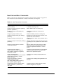
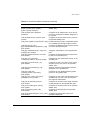
New Commands
New ExtremeWare Commands
A-1
A-2
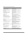
Changed Commands
A-5
Contents
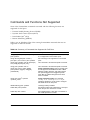
Commands and Functions Not Supported
B
A-8
Supported MIBs and Standards
SONET/SDH Support
Standards Supported for SONET/SDH
MIBs Supported for SONET/SDH
B-2
B-2
B-2
PPP Support
Standards Supported for PPP
MIBs Supported for PPP
B-2
B-2
B-3
QoS and DiffServ Support
Standards Supported for DiffServ
B-3
B-3
Flow Statistics Support
MIBs Supported for Flow Statistics
B-4
B-4
Automatic Protection Switching Support
Standards Supported for APS
MIBs Supported for APS
B-4
B-5
B-5
Index
Index of Commands
Contents
vii
viii
Contents
Figures
1-1
1-2
1-3
2-1
2-2
3-1
3-2
3-3
3-4
3-5
3-6
3-7
3-8
3-9
3-10
3-11
3-12
3-13
3-14
3-15
3-16
3-17
3-18
3-19
3-20
Figures
PoS module
Front panel views of the P3cSi and P3cMi modules
Front panel views of the P12cSi and P12cMi modules
Slot locations in a BlackDiamond 6800 series chassis
Inserting and securing a PoS module
Default configuration for BCP
IPCP configuration
APS configuration, port redundancy
APS configuration, module redundancy
APS configuration for switch redundancy
View of logical connectivity to PoS ports with IPCP enabled
View of logical connectivity to PoS ports with BCP enabled
Comparisons of RED and WRED operation
Format of NetFlow export datagram
NetFlow Collection Architecture Example
Linear 1+1 APS architecture
Linear 1+1 APS architecture with two switches
Virtual APS router configuration
Logical PPP connectivity to virtual APS router
Format of SONET K1 and K2 Bytes
Typical redundant switch configuration without APS
Redundant switch configuration with APS
APS configuration providing faster recovery from
line failure
APS in bridging configuration
Port tunneling via a PPP link
1-4
1-6
1-7
2-6
2-8
3-4
3-6
3-8
3-9
3-10
3-24
3-25
3-53
3-61
3-63
3-75
3-76
3-78
3-79
3-80
3-82
3-83
3-84
3-85
3-98
ix
x
Figures
Tables
1
2
2-1
3-1
3-2
3-3
3-4
3-5
3-6
3-7
3-8
3-9
3-10
3-11
3-12
3-13
3-14
3-15
3-16
3-17
3-18
3-19
A-1
Tables
Notice Icons
Text Conventions
PoS Module and Port LEDs
SONET Parameters and Values
SONET Port Commands
Summary of SONET Statistics
SONET Events
PPP Commands
VLAN-related Commands
QoS-Related Commands
Default Code Point-to-QoS Profile Mapping
Assured Forwarding Classes and Three-Level
Drop Precedence
Assured Forwarding Classes and Two-Level
Drop Precedence
Mapping PHBs to QoS Profiles
NetFlow Version 1 Record Format
Format of NetFlow Version 1 Export Datagram Header
Flow Statistics Commands
APS Protocol for Switch from Working Line to
Protection Line
APS Commands
Changes to General Switch Commands
Changes to Port Commands
Changes to Image Commands
New ExtremeWare Commands
xiv
xv
2-12
3-5
3-13
3-18
3-19
3-26
3-38
3-43
3-48
3-56
3-56
3-56
3-60
3-62
3-65
3-81
3-86
3-101
3-103
3-106
A-2
xi
A-2
A-3
A-4
xii
Summary of Commands with Enhanced Syntax
Summary of Commands with Augmented Implementation
Summary of Commands Not Supported for PoS Ports
A-5
A-6
A-8
Tables
Preface
This Preface provides an overview of this guide, describes guide conventions, and lists
other publications that may be useful.
Introduction
This guide provides the required information to install the PoS module in a
BlackDiamond® 6800 series switch from Extreme Networks and perform the initial
module configuration tasks.
This guide is intended for use by network administrators who are responsible for
installing and setting up network equipment. It assumes a basic working knowledge of:
• Local area networks (LANs).
• Ethernet concepts.
• Ethernet switching and bridging concepts.
• Routing concepts.
• Internet Protocol (IP) concepts.
• Routing Information Protocol (RIP) and Open Shortest Path First (OSPF).
• Simple Network Management Protocol (SNMP).
If the information in the release notes shipped with your module differs from the
information in this guide, follow the release notes.
Packet Over SONET Module Installation and User Guide
xiii
Terminology
When features, functionality, or operation is specific to one of the PoS modules, the
specific module name is used. Explanations about features and operations that are the
same across all of the PoS modules simply refer to the product as the “module.”
Switches and switch modules that use naming conventions ending in “i” have
additional capabilities that are documented throughout this user guide. For the most
current list of products supporting the “i” chipset, consult your release notes.
Unless otherwise specified, a feature requiring the “i” chipset requires the use of both
an “i” chipset-based management module, such as the MSM64i, and an “i”
chipset-based I/O module, such as the G8Xi.
Conventions
Table 1 and Table 2 list conventions that are used throughout this guide.
Table 1: Notice Icons
Icon
xiv
Notice Type
Alerts you to...
Note
Important features or instructions.
Caution
Risk of personal injury, system damage, or loss of data.
Warning
Risk of severe personal injury.
Packet Over SONET Module Installation and User Guide
Related Publications
Table 2: Text Conventions
Convention
Description
Screen displays
This typeface indicates command syntax, or represents information
as it appears on the screen.
Screen displays
bold
This typeface indicates how you would type a particular command.
The words “enter”
and “type”
When you see the word “enter” in this guide, you must type
something, and then press the Return or Enter key. Do not press the
Return or Enter key when an instruction simply says “type.”
[Key] names
Key names are written with brackets, such as [Return] or [Esc].
If you must press two or more keys simultaneously, the key names
are linked with a plus sign (+). Example:
Press [Ctrl]+[Alt]+[Del].
Words in italicized type
Italics emphasize a point or denote new terms at the place where
they are defined in the text.
Related Publications
The publications related to this one are:
• ExtremeWare™ release notes
• ExtremeWare Software User Guide
• BlackDiamond 6800 Series Switch Hardware Installation Guide
• BlackDiamond Module Installation Note
Documentation for Extreme Networks products is available on the World Wide Web at
the following location:
http://www.extremenetworks.com/
Packet Over SONET Module Installation and User Guide
xv
xvi
Packet Over SONET Module Installation and User Guide
1
Overview
The Packet over SONET (PoS) modules are I/O modules for the BlackDiamond 6800
series chassis-based system. These modules connect a BlackDiamond 6800 series switch
to the SONET infrastructure used by metropolitan area service providers and operators
of server co-location networks.
This chapter includes information on the following topics:
• BlackDiamond 6800 Series Switch Overview on page 1-1
• About the PoS Modules on page 1-3
BlackDiamond 6800 Series Switch Overview
The BlackDiamond 6800 series switch is a chassis-based switch designed to be placed in
the core of your network. The BlackDiamond 6800 series switch is flexible and scalable,
making it easy for you to meet the changing requirements of your network. The
combination of BlackDiamond, Alpine™, and Summit™ switches delivers a consistent
end-to-end network solution that provides a nonblocking architecture, wire-speed
switching, wire-speed IP routing, and policy-based Quality of Service (QoS).
Packet Over SONET Module Installation and User Guide
1-1
Overview
BlackDiamond I/O Modules
In addition to the PoS modules described in this guide, the BlackDiamond 6800 series
switch supports a variety of I/O modules that offer a choice of port connections over
different media types and distances. For more information, see the BlackDiamond 6800
Series Switch Hardware Installation Guide.
BlackDiamond 6800 series I/O modules can be inserted or removed at any time,
without causing disruption of network services. No configuration information is stored
on the I/O modules; all configuration information is stored on the MSM64i modules.
When the BlackDiamond 6800 series switch is powered on, the ExtremeWare software
determines which slots are occupied by I/O modules, determines whether it has a
configuration for each module, and generates a default configuration for each slot that
is occupied by an I/O module that has not yet been configured. The default
configuration is the minimal set of configuration parameter settings that will allow the
I/O module and its ports to function. The default configuration for the I/O module is
not preserved unless you explicitly save the information to nonvolatile RAM (NVRAM).
You can also use ExtremeWare commands to configure the I/O module after installing it
in the BlackDiamond chassis, or you can preconfigure the parameters of a module that
has not yet been inserted into the chassis.
If you preconfigure a slot for a particular module, the preconfigured information is used
when the module is inserted. You must select a module type for the slot before you can
preconfigure the parameters. If you have preconfigured a slot for a specific module type
and then insert a different type of module, you must explicitly overwrite the existing
configuration with a new configuration, or use the ExtremeWare unconfig
slot <slot> command to clear the existing slot configuration. If you enter a new
configuration for the new module, the module uses that configuration. If you clear the
slot configuration, the new module type can use the default configuration ExtremeWare
creates.
For information on configuring I/O modules, see the ExtremeWare Software User
Guide.
1-2
Packet Over SONET Module Installation and User Guide
About the PoS Modules
About the PoS Modules
Two key applications for the PoS modules are: interconnecting metropolitan area
networks across the SONET network infrastructure, and interconnecting server
co-location network sites directly using SONET links.
In the first application, the metropolitan area network service provider can build service
network sites in various cities, then use PoS modules in a BlackDiamond 6800 series
switch to connect those cities to a carrier’s SONET infrastructure.
In the second application, operators of server co-location networks can use PoS modules
in BlackDiamond 6800 series switches to create a SONET-based connection between
server co-location sites. The result is that their network is simpler to manage, and
problems can be isolated and resolved more expediently.
Extreme Networks offers the PoS module in the following configurations:
• P3cMi: four OC-3 multimode, short-reach optical interfaces
• P3cSi: four OC-3 single-mode, intermediate-reach optical interfaces
• P12cMi: two OC-12 multimode, short-reach optical interfaces
• P12cSi: two OC-12 single-mode, intermediate-reach optical interfaces
The “c” in the names of the modules indicates that the optical interfaces on
these modules operate in concatenated mode, which enables all the bandwidth
to be devoted to a single payload stream.
The P3cMi (multimode version) operates in the 1310 nanometer (nm) wavelength
window at a typical maximum cable distance of 2 kilometers (km) or 1.24 miles (mi).
The P12cMi (multimode version) also operates in the 1310 nanometer (nm) wavelength,
but at a typical maximum cable distance of 500 meters (m) or 0.31 (mi). The P3cSi and
P12cSi (single-mode versions) also operate in the 1310 nanometer (nm) wavelength
window, but at a typical maximum cable distance of 15 km or 9.32 (mi). All four
versions of the PoS module use industry-standard duplex SC optical fiber connectors.
Packet Over SONET Module Installation and User Guide
1-3
Overview
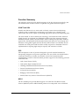
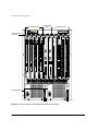
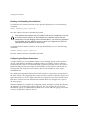
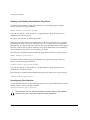
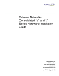
Physical Description
The PoS module consists of a printed circuit board mounted on a metal carrier that acts
as the insertion vehicle in a BlackDiamond 6800 series switch (see Figure 1-1). The
module carrier also includes ejector/injector handles and captive retaining screws at
each end of the module front panel. The module occupies one slot in a BlackDiamond
6800 series switch.
Captive
retaining screw
Module status LED
Module diagnostics LED
Ejector/injector
handle
Network processors
and heat sinks
Network interface ports
Two on OC-12 PoS module
Four on OC-3 PoS module
Port status LED
(one per port)
Service ports
General Purpose Processor (GPP)
PoS_002
Figure 1-1: PoS module
1-4
Packet Over SONET Module Installation and User Guide
About the PoS Modules
The PoS module has the following key components:
• Two high-performance network processors
• A General Purpose Processor (GPP) subsystem
The network processors are programmable devices that participate with the Extreme “i”
chipset to support expanded functionality, features, and flexibility.
The GPP subsystem handles system control and I/O module management functions.
The GPP subsystem resides outside of the I/O module data path to optimize
performance.
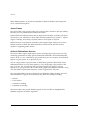
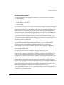
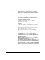
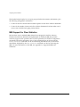
PoS Module LED Indicators
The PoS modules are equipped with two module-level LED indicators (STATUS and
DIAG) and one port-level LED indicator for each network interface port on the PoS
module (see Figure 1-2 and Figure 1-3).
The STATUS LED indicator is located near the top end of the PoS module front panel,
near the ejector/injector handle. This LED indicator is a bi-color LED (displaying in
either green or amber) that signals the operating status of the module as a whole.
The DIAG LED indicator is located beside the STATUS LED. This LED is a single-color
LED (displaying in amber only) that flashes amber when diagnostics are running on the
module, and is solid amber if the module fails the diagnostics.
The port-level LED is an LED next to the port number identifying each fiber optic
network interface connector on the front panel of the module. The port LED is a bi-color
LED (displaying in either green or amber) that signals the operating status of that
network interface port.
For more information on PoS module LED states and their use in troubleshooting PoS
module problems, see “Verifying the Module Installation” on page 2-10.
Service Ports
The PoS modules are equipped with two front-panel service ports: one port is a
subminiature DB-9 connector; the other is a micro HD-15 connector (see Figure 1-1).
Both ports are reserved for use only by Extreme Networks technical support personnel
for diagnostic purposes.
Packet Over SONET Module Installation and User Guide
1-5
Overview
Module status LEDs
Port
status
LEDs
Network
interface
ports
Port
status
LEDs
Service ports
BD_P3
Figure 1-2: Front panel views of the P3cSi and P3cMi modules
1-6
Packet Over SONET Module Installation and User Guide
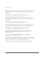
About the PoS Modules
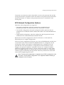
Module status LEDs
Port
status
LEDs
Network
interface
ports
Port
status
LEDs
Service ports
BD_P12
Figure 1-3: Front panel views of the P12cSi and P12cMi modules
Feature Summary
The PoS modules provide the following key networking functions:
• Support for both Synchronous Optical Network (SONET) and Synchronous Digital
Hierarchy (SDH) modes of operation
• Support for the Point-to-Point Protocol (PPP) suite, including:
— Link Control Protocol (LCP)
— Link Maintenance option for LCP
— Link Quality Report (LQR) Protocol
— Password Authentication Protocol (PAP)
— Challenge Handshake Authentication Protocol (CHAP)
— IP Control Protocol (IPCP)
— Bridging Control Protocol (BCP)
— Extreme Discovery Protocol Control Protocol (EDPCP)
Packet Over SONET Module Installation and User Guide
1-7
Overview
• Efficient support for IP routing over SONET via IPCP
• Support for Transparent LAN Services (TLS) over SONET via BCP
• Support for MultiProtocol Label Switching Control Protocol (MPLSCP) via PPP
• Support for jumbo frames
• Extensive support for Quality of Service (QoS) and Differentiated Services (DiffServ),
including:
— Eight ingress queues and eight egress queues per interface
— Ingress and egress rate shaping and limiting
— IEEE 802.1Q VLAN priorities
— Weighted RED (WRED) congestion avoidance algorithm
— Assured Forwarding and Expedited Forwarding RFCs
• Support for service provider specific features, such as:
— Flexible remapping of DiffServ codepoints
— Flexible remapping of IEEE 802.1Q VLAN IDs
— VLAN tunneling via nested 802.1Q tags
— Port tunneling of High-Level Data Link Control (HDLC) byte streams
• Support for NetFlow Version 1 per-flow statistics, including:
— Capacity for two million flow records per PoS module
— Scalability via distribution to groups of flow-record collector devices
— Filters enabling statistics to be maintained for selected flows
— Aggregation option for further reducing the volume of exported data
• Resiliency with fast recovery from SONET link failures via support for Automatic
Protection Switching (APS) protocol in multiple configurations, including networks
where the working and protection lines are:
— Terminated in the same SONET module
— Terminated in different SONET modules residing in the same BlackDiamond 6800
series system
— Terminated in different SONET modules residing in different BlackDiamond 6800
series systems
1-8
Packet Over SONET Module Installation and User Guide
About the PoS Modules
Function Summary
The following sections provide brief descriptions of the key functions provided by the
PoS modules. Each of these sections is expanded into greater detail in Chapter 3.
SONET and SDH
SONET and SDH are the two terms used to identify a time division multiplexing
technology that is optimized for transporting voice traffic across a digital optical
network, but that is also capable of providing high-speed capacity for transporting data.
The term SONET is used to identify the technology used within the North American
digital network. Its standards are published by Bellcore and the American National
Standards Institute (ANSI). The term SDH is used to identify the equivalent standard
approved by the International Telecommunication Union (ITU) for use in Europe and
elsewhere in the global digital network. Because SDH evolved out of SONET, the two
standards are closely joined and have been widely accepted as a dominant choice for
implementations requiring high transport capacity and resistance to failure.
PPP
PPP encompasses a suite of protocols designed to provide standard methods for
transporting datagrams over point-to-point links. The use of PPP over SONET links is
commonly referred to as Packet over SONET, or PoS. The Extreme Networks
implementation of PPP for the PoS module provides support for the following protocols
in the PPP suite:
• Link Control Protocol (LCP)
• Link Quality Report (LQR) Protocol
• Challenge Handshake Authentication Protocol (CHAP)
• Password Authentication Protocol (PAP)
• IP Control Protocol (IPCP)
• Bridging Control Protocol (BCP)
• Extreme Discovery Protocol Control Protocol (EDPCP)
MPLS
The PoS module ports provide MPLS support via a PPP link. The MPLS Control
Protocol (MPLSCP) allows MPLS labeled packets to be transported across a PPP link.
Packet Over SONET Module Installation and User Guide
1-9
Overview
MPLS labeled packets can also be encapsulated in Ethernet headers and transported
across a PPP link using BCP.
Jumbo Frames
The PoS module ports provide jumbo frame support that is similar to that provided by
Ethernet ports on a BlackDiamond 6800 series switch.
Jumbo frames are Ethernet frames that are larger than 1522 bytes, including four bytes
used for the cyclic redundancy check (CRC). Extreme products that use the “i” chipset
support switching and routing of jumbo frames at wire-speed on all ports.
Jumbo frames are used between endstations that support larger frame sizes for more
efficient transfers of bulk data. Both endstations involved in the transfer must be
capable of supporting jumbo frames.
QoS and Differentiated Services
The PoS modules support eight ingress queues and eight egress queues per port. The
scheduling parameters for these queues (minimum bandwidth, maximum bandwidth,
priority level, etc.) are controlled by QoS profiles that you can customize for individual
ingress or egress queues on a specific PoS port.
You can assign frames to queues based on IEEE 802.1p priorities, MPLS EXP values,
Differentiated Services Code Points (DSCPs), or by configuring a QoS profile for the
port or VLAN. You can tailor the DSCP-to-queue mapping for ingress or egress
directions on a per-port basis. Most of the existing ingress classification functions, along
with the DiffServ replacement functions, are also supported for PoS ports.
The supported DiffServ functions maximize user flexibility while providing all of the
features needed to support the standard per-hop behaviors (PHBs), including:
• Default
• Class Selector
• Assured Forwarding
• Expedited Forwarding
The PoS modules also provide flexible support for the well-known Weighted RED
(WRED) congestion avoidance algorithm.
1-10
Packet Over SONET Module Installation and User Guide
About the PoS Modules
Service Provider Features
The PoS modules provide the following features for service provider environments:
• DSCP mapping
• VLAN ID (VID) tag mapping
• VLAN ID (VID) tag nesting
• Port tunneling
You can use the diffserv dscp-mapping command to configure a mapped relationship
between an input DSCP and an associated output DSCP. Each PoS port supports three
DSCP mapping tables: one of the tables is used in the ingress direction; two are used for
egress flows (onto the SONET link). The two egress tables are for the congested and
noncongested states, as determined by the RED algorithm. If RED is not enabled on the
PoS port, the egress congested-state mapping table is not used.
In the ingress direction, the input DSCP of a packet received from the SONET link is
replaced by an output DSCP before the packet is forwarded. In the egress direction, the
operation is similar, except that the DSCP mapping occurs before the packet is
transmitted onto the SONET link.
One potential use of the DSCP mapping capability is to reconcile varying DiffServ
policies at the boundary between autonomous systems, such as at the boundary
between two ISPs. The availability of different tables for the congested and
noncongested states is useful in marking operations that increase the probability of
packets being dropped during times of congestion, as discussed in the DiffServ Assured
Forwarding RFC (RFC 2597).
An analogous feature has been added for managing 802.1Q tags. The
dot1q tagmapping command provides support for VLAN ID (VID) mapping tables.
Each PoS port supports two VID tables: one table is used in the ingress direction; the
other is used in the egress direction. Each of the tables enables an input VID to be
mapped to an output VID. This feature is useful in reconciling policy differences at the
boundary between the customer and the service provider.
Another related enhancement provides support for nested 802.1Q tags by allowing a
tag push or tag pop attribute to be associated with a VID. The push attribute indicates that
a new tag is to be added to the frame, while the pop attribute indicates that the top-level
tag is to be removed from the frame. This capability is augmented by an option that
allows the 802.1p priority of the frame to be either preserved or set to a
user-configurable value when a new tag is pushed. These functions make it possible for
service providers to tunnel customer-specific VLANs across a common SONET
backbone in a very simple manner.
Packet Over SONET Module Installation and User Guide
1-11
Overview
The PoS module also supports port tunneling. Port tunneling can be used to
encapsulate and transport the raw High-Level Data Link Control (HDLC) encapsulated
byte stream from one PoS port to another PoS port across an MPLS network. This
allows service providers to tunnel different types of SONET HDLC streams across a
non-SONET backbone like Ethernet.
NetFlow Statistics
Each PoS port can maintain and export statistics for the flows that traverse the
associated SONET link.
Per-flow statistics are useful for many management purposes, including:
• Accounting and billing
• Network capacity planning and trend analysis
• Network monitoring
• Workload characterization
• User profiling
• Data warehousing and mining
Each PoS module can maintain two million flow records. Per-flow statistics are reported
in the NetFlow, Version 1 format, which groups flow records together into UDP
datagrams for export to a flow-collector device.
The PoS module also provides a NetFlow distribution feature to provide a growth path
to more scalable and robust collection architectures. This feature allows a single PoS
port to distribute statistics across multiple groups of flow-collector devices in a
load-balanced manner. The function also includes a health-check feature that
significantly improves the reliability of the collection architecture. The health-checker
ensures that only responsive flow-collector devices are included in the effective export
distribution lists.
To further enhance scalability, the PoS module also offers filters and filter-based
aggregation options that allow you to configure a PoS port to maintain statistics
selectively for only those flows matching specified filters. The aggregation options can
further reduce the volume of exported data by enabling a single set of statistics to be
maintained for all the flows that match an aggregation filter.
1-12
Packet Over SONET Module Installation and User Guide
About the PoS Modules
Automatic Protection Switching
Automatic Protection Switching, or APS, is a physical-layer resiliency feature specified
in the SONET standards. Multiplex Section Protection, or MSP, is the APS equivalent in
the SDH standard, which is also supported by the PoS module. Throughout this guide,
the terms APS and Automatic Protection Switching are used to refer to the protection
switching features of both standards.
Of the various protection switching modes specified in the SONET/SDH standards, the
BlackDiamond 6800 series switches use the linear 1+1 architecture to protect tributary
SONET lines. In the linear 1+1 architecture, there is one protection line for each working
line. If the working line fails, traffic is automatically switched to the protection line. You
can also control whether traffic switched to the protection line is automatically switched
back to the working line when it is restored to service.
The Extreme Networks implementation supports network configurations where:
• Working and protection lines are terminated in the same PoS module.
• Working and protection lines are terminated in different PoS modules residing in the
same BlackDiamond 6800 series switch.
• Working and protection lines are terminated in different PoS modules residing in
different BlackDiamond 6800 series switches.
Packet Over SONET Module Installation and User Guide
1-13
Overview
1-14
Packet Over SONET Module Installation and User Guide
2
Installing or Replacing a
PoS Module
This chapter includes information on the following topics:
• Preparing for Installation on page 2-1
• Inserting and Securing a Module on page 2-7
• Making Network Interface Cable Connections on page 2-9
• Verifying the Module Installation on page 2-10
• Troubleshooting on page 2-11
• Removing and Replacing an I/O Module on page 2-16
Preparing for Installation
This section describes the preparation steps that you must perform before inserting and
securing a PoS module. This section includes information on the following topics:
• Software and Hardware Version Requirements on page 2-2
• Cables and Connectors on page 2-3
• Safety Information on page 2-4
• Tools on page 2-5
• I/O Module Slot Locations on page 2-5
Packet Over SONET Module Installation and User Guide
2-1
Installing or Replacing a PoS Module
Software and Hardware Version Requirements
The PoS modules are compatible with “i”-series MSM modules only, but are compatible
with both Summit and “i”-series I/O modules. For the most current list of I/O modules
supported for use with the PoS modules, consult your release notes.
Software support for PoS modules is provided in an ExtremeWare technology release,
which is a software release providing specialized hardware support and/or additional
functionality not found in the current mainstream ExtremeWare release.
The ExtremeWare technology release that supports PoS modules includes multiple
software packages. One software package runs on the MSM module, while another
package runs on each PoS module. These software packages are downloaded
independently using the ExtremeWare download image command. Each software
package has an associated version number that you can display by using the
show version command. As a recommendation (not a requirement), the MSM software
package and the PoS module software package should be the same version. To ensure
compatibility, the MSM performs an automatic compatibility check before a PoS module
is activated. In case of incompatibility, the PoS ports on the module will not come up
and the show slot command will indicate that the software on the PoS module is
incompatible with the software on the MSM.
You can also verify compatibility by comparing the version of the MSM software
package with the version of the PoS module software package. The format of the
software version field of the ExtremeWare software version identifier has been extended
to support technology releases. The following example of the ExtremeWare software
version identifier illustrates the extended version format:
ExtremeWare V6.1.5 (Build 20) Project IP_SERV_TECH_REL V1.2.64
In this example, the technology release-specific version information Project
IP_SERV_TECH_REL V1.2.64 is added to the base ExtremeWare version identifier
ExtremeWare V6.1.5 (Build 20) to form the extended version identifier format. The first
field of the version identifier, ExtremeWare V6.1.5 (Build 20), identifies the ExtremeWare
software version on which this technology release is based. The second field in the
extended version identifier, Project IP_SERV_TECH_REL, is the name of the technology
release. The final field, V1.2.64 is a three-part number that identifies the version of the
technology release. In the example, the first part of the number, 1, is the extended major
version number; the second part of the number, 2, is the extended minor version number;
the third part of the number, 24, is the extended build version number.
2-2
Packet Over SONET Module Installation and User Guide
Preparing for Installation
The MSM software package is compatible with the PoS module software package when
the following conditions are true:
• Base ExtremeWare version numbers match
• Technology release names match
• Extended major version numbers match
• Extended minor version number of the MSM software package is equal to or greater
than the extended minor version of the PoS module software package
The extended build number is ignored for compatibility comparisons.
For example, MSM software package ExtremeWare V6.1.5 (Build 20) Project
IP_SERV_TECH_REL V1.2.64 is compatible with PoS module software package
ExtremeWare V6.1.5 (Build 20) Project IP_SERV_TECH_REL V1.1.98, but is not compatible
with PoS module software package ExtremeWare V6.1.5 (Build 20) Project
IP_SERV_TECH_REL V2.1.1.
Cables and Connectors
Extreme Networks offers the PoS module in the following configurations:
• P3cMi: four OC-3 multimode, short-reach optical interfaces
• P3cSi: four OC-3 single-mode, intermediate-reach optical interfaces
• P12cMi: two OC-12 multimode, short-reach optical interfaces
• P12cSi: two OC-12 single-mode, intermediate-reach optical interfaces
The “c” in the names of the modules indicates that the optical interfaces on
these modules operate in concatenated mode, which enables all the bandwidth
to be devoted to a single payload stream.
The P3cMi (multimode version) operates in the 1310 nanometer (nm) wavelength
window at a typical maximum cable distance of 2 kilometers (km) or 1.24 miles (mi).
The P12cMi (multimode version) also operates in the 1310 nanometer (nm) wavelength,
but at a typical maximum cable distance of 500 meters (m) or 0.31 (mi). The P3cSi and
P12cSi (single-mode versions) also operate in the 1310 nanometer (nm) wavelength
window, but at a typical maximum cable distance of 15 km or 9.32 (mi). All four
versions of the PoS module use industry-standard duplex SC optical-fiber connectors.
Packet Over SONET Module Installation and User Guide
2-3
Installing or Replacing a PoS Module
Use the appropriate type of optical-fiber cable—single-mode or multimode—to connect
the PoS ports of your BlackDiamond 6800 series switch to another switch or router.
Single-mode and multimode optical-fiber cables can be acquired from a number
of different cable vendors, including AMP, Anixter, AT&T, Red-Hawk, and
Siemens.
Safety Information
Before you begin the process of installing or replacing a PoS module in a BlackDiamond
6800 series system, read the safety information in this section.
Failure to observe the necessary safety guidelines can lead to personal injury or
damage to the equipment.
In addition, observe the following safety guidelines:
• All service to components of a BlackDiamond 6800 series switch, including I/O
modules, should be performed by trained service personnel only. Service personnel
are persons having appropriate technical training and experience necessary to be
aware of the hazards to which they are exposed in performing a task and of
measures to minimize the danger to themselves or other persons.
The PoS modules use electronic components that are sensitive to static
electricity. Electrostatic discharge (ESD) originating from you or from objects
around you can damage these components. Exercise every possible
precaution to prevent ESD when working around printed circuit assemblies.
Keep all printed circuit assemblies in protective ESD-preventive sacks or
place them on antistatic mats until you are ready to install them. Wear an
ESD-preventive wrist strap and ensure that the leash is securely grounded
before handling a bare printed circuit assembly.
• This device contains fiber optic ports. To protect your eyes, you should never look at
the fiber optic ports while they are on, or look directly at the fiber cable ends when
they are on.
• This module is a Class 1 laser device.
2-4
Packet Over SONET Module Installation and User Guide
Preparing for Installation
Tools
You need the following tools to install an Extreme Networks I/O module in a
BlackDiamond 6800 series chassis.
• ESD-preventive wrist strap and grounding leash that is provided with the
BlackDiamond 6800 series chassis.
• Number 1 Phillips-head screwdriver.
• Optical-fiber cable of the type appropriate to the I/O module version you plan to
install (see “Cables and Connectors” on page 2-3 for more information about cable
and connector requirements).
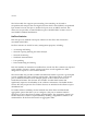
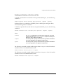
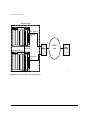
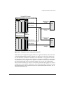
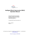
I/O Module Slot Locations
Figure 2-1 shows the I/O module slot locations in the BlackDiamond 6800 series chassis.
You can install the PoS module in any of the numbered slots labeled slots 1 through 8.
I/O modules do not fit in slots A or B. When you are installing a new PoS module, you
must first remove the blank filler from the available slot.
To ensure a sufficient flow of cooling air across the component side of the PoS
module, install the PoS module in the BlackDiamond 6800 series chassis so that
another module, a blank filler, or the far right chassis wall covers the component
side of the module.
Packet Over SONET Module Installation and User Guide
2-5
Installing or Replacing a PoS Module
MSM module
slots
I/O module slots
ESD wrist strap
connector
1
2
3
4
A
B
50015
50015
I/O module slots
5
6
7
8
51032
51040
52011
STATUS
STATUS
DIAG
DIAG
R
ER
G
DIA
S
TU
STA
V
EN
R
ST
M
S
SY
R
ER
V
EN
R
ST
M
S
SY
1
1
9
17
25
2
10 18
26
1
5
9
2
6
10
3
7
11
4
12
20
28
4
8
12
5
13
21
29
6
14
22
30
7
15
23
31
8
16
24
32
3
= ACTIVITY
AMBER
= LINK OK
GREEN
FLASHING GREEN = DISABLED
11 19
AMBER
=
ACTIVITY
27
GREEN
=
LINK OK
FLASHING
GREEN
=
DISABLED
2
1
17
1
CONSOLE
3
CONSOLE
2
3
4
20
5
21
4
4
MODEM
MODEM
5
5
6
MGMT
MGMT
8
24
9
25
6
7
LINK /
ACTIVITY
LINK /
ACTIVITY
8
7
9
12
28
13
29
10
8
11
PCMCIA
PCMCIA
12
POWER
16
32
POWER
DC OUT
DC OUT
AC IN
AC IN
50021
50021
Power supplies
V-50/60Hz
200-240V, 15A
V-50/60Hz
200-240V, 15A
PoS_003
Figure 2-1: Slot locations in a BlackDiamond 6800 series chassis
2-6
Packet Over SONET Module Installation and User Guide
Inserting and Securing a Module
Inserting and Securing a Module
This section describes the procedures for inserting and securing a PoS module.
Caution: I/O modules must be installed in any of the numbered chassis slots
labeled slots 1 through 8. I/O modules do not fit in slots A or B. Forceful
insertion can damage the I/O module.
1 Before you install modular cards in the BlackDiamond 6800 series chassis, put on the
ESD-preventive wrist strap that is provided with the chassis, and connect the metal
end of the grounding leash to the ground receptacle located on the top-left corner of
the BlackDiamond 6800 series switch front panel.
Leave the ESD-preventive wrist strap permanently connected to the BlackDiamond
6800 series chassis so that it is always available when you need to handle
ESD-sensitive switch components.
2 Identify the chassis slot for the module. If necessary, remove the blank filler from the
slot to make room for the PoS module.
Any unoccupied module slot in the chassis should have a blank filler installed
for electromagnetic compatibility (EMC) and to ensure adequate airflow
through the chassis.
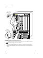
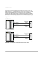
3 To insert a PoS module, use Figure 2-2 as a reference and follow these steps:
To prevent ESD damage, handle the PoS module by the metal card carrier
edges only. Never touch components on the printed circuit board or pins on
any of the connectors. Never attempt to lift or hold the module by using the
heat sinks on either of the network processors.
a Grasp the module by its front panel with one hand and place your other hand
under the edge of the metal card carrier to support the weight of the module.
b Ensure that the module is right side up (printed circuit board, or PCB, facing to
the right) and that the ejector/injector handles are fully extended.
c
Carefully align the upper and lower edges of the metal card carrier in the chassis
slot and slide the module slowly into the slot, taking particular care that the heat
sinks on the two network processors are not obstructed in any way.
d Continue sliding the module into the chassis slot until the ejector/injector
handles make contact with the front edges of the chassis slot, then stop.
Packet Over SONET Module Installation and User Guide
2-7
Installing or Replacing a PoS Module
(a) Loosen
captive screws
1
2
3
4
A
B
50015
50015
5
6
7
8
(b) Pivot
ejector/injector
handles
POWER
POWER
DC OUT
AC IN
50020
DC OUT
AC IN
50020
PoS_004
Figure 2-2: Inserting and securing a PoS module
When the module is pushed into the chassis slot, the ejector/injector handles
will begin pivoting to their closed position.
e To seat the module in the backplane connectors, completely close the module
ejector/injector handles by pushing them toward the center of the module front
panel.
2-8
Packet Over SONET Module Installation and User Guide
Making Network Interface Cable Connections
f
Use a #1 Phillips-head screwdriver to tighten the captive screw on each end of
the module front panel to prevent the module from being dislodged from the
backplane connectors and to ensure satisfactory protection from EMI.
Repeat this procedure for additional modules, if applicable.
Making Network Interface Cable Connections
Use the appropriate type of optical-fiber cable—single-mode or multimode—to connect
the PoS ports of your BlackDiamond 6800 series switch to another switch or router.
Kinks and sharp bends can destroy or impair the cable’s ability to convey light
pulses accurately from one end of the cable to the other. Use care in dressing
the optical-fiber cables: provide satisfactory strain relief to support the cable and
maintain an adequate bend radius at all cable turns, particularly where the cable
connects to the I/O module.
Working carefully, one port at a time, follow these steps:
1 Verify that you have identified the correct optical-fiber cable for the PoS module
port.
2 Use an alcohol wipe or other appropriate cleaning agent to clean the fiber element
on the cable connectors to be sure they are free of dust, oil, and other contaminants.
3 Align the transmit (Tx) and receive (Rx) connectors on the optical-fiber cable with
the correct corresponding connectors on the PoS module.
On the PoS modules, the transmit (Tx) connector on each port is the top connector.
4 Press the cable connectors into their mating connectors on the PoS module until the
cable connector is firmly seated.
5 Repeat steps 1 through 4 for the remaining cables on this or other PoS modules.
6 Dress and secure the cable bundle to provide appropriate strain relief and protection
against bends and kinks.
Packet Over SONET Module Installation and User Guide
2-9
Installing or Replacing a PoS Module
Verifying the Module Installation
After you have installed the PoS module and connected the fiber optic cables, verify
that the I/O module is working correctly. Check the LEDs on the front panel of the I/O
module and use the command-line interface (CLI) show slot <slot> command to
display slot-specific information about the newly installed module.
LED Indicators
When the PoS module and its ports are configured and operating normally, the
front-panel LED indicators should appear as follows:
• STATUS LED indicator: flashing green
• DIAG LED indicator: off
• Port status LED indicators (per port):
— Green: The link is operational.
— Green blinking: The link is disabled.
— Amber blinking, returning to green: There is activity on the link.
— Amber blinking: The link is down (SONET error).
— Off: No signal was received.
Displayed Slot Status Information
Assuming that there are no other problems with the PoS module, the command
show slot n (where n is the number of the slot where you installed the module) will
show that ExtremeWare has detected the module and set it to the OPERATIONAL state.
As the module progresses through its initialization, the show slot n command will
show the GPP subsystem change state to OPERATIONAL, and then each of the network
processors will change state to OPERATIONAL.
When the GPP subsystem has completed its initialization cycle and the
subsystem state is OPERATIONAL, you can use the show diagnostics
{<slot>} command to check the results of the module’s power-on self test
(POST).
2-10
Packet Over SONET Module Installation and User Guide
Troubleshooting
Troubleshooting
This section describes how to isolate module-specific problems and determine when it
is appropriate to remove and replace a PoS module. This section includes information
on the following topics:
• Identifying Problem Categories on page 2-12
• Fixing Configuration Errors on page 2-13
• Upgrading the Switch Software Image on page 2-14
• Upgrading the PoS Module Software Image on page 2-14
• Fixing Power-Related Problems on page 2-15
• Fixing Link Down Problems on page 2-15
• Identifying Conditions for Replacing an I/O Module on page 2-16
The information in this section should be used in conjunction with the
“Troubleshooting” appendix in the ExtremeWare Software User Guide and the
release notes that accompanied your Extreme Networks product. If you
encounter a problem that is not discussed in one of these resources, contact
Extreme Networks technical support.
Packet Over SONET Module Installation and User Guide
2-11
Installing or Replacing a PoS Module
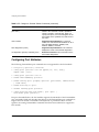
Identifying Problem Categories
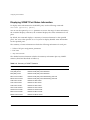
Table 2-1 lists the color states of PoS module and port LEDs and describes their
associated meanings. The STATUS and DIAG LEDs apply to the module as a whole; the
port status LED for each port provides status information about that port.
Table 2-1: PoS Module and Port LEDs
LED
Color
Indicates
Corrective action
STATUS
Green blinking
Normal operation
(No action required.)
Amber blinking
Configuration error (configured
slot type is different than
inserted module type)
See “Fixing Configuration
Errors” on page 2-13.
Version error (ExtremeWare
version does not recognize
inserted module)
See “Upgrading the Switch
Software Image” on
page 2-14.
Version error (the PoS module See “Upgrading the PoS
image version is not compatible Module Software Image”
with the MSM image version)
on page 2-14.
DIAG
2-12
Hardware error (module failed
diagnostics)
See “Identifying Conditions
for Replacing an I/O
Module” on page 2-16.
Network processor or GPP
down (as detected by network
processor heartbeat protocol)
Reboot slot. If condition
persists, run diagnostics.
Off
No power
See “Fixing Power-Related
Problems” on page 2-15.
Amber blinking
Diagnostics in progress
(No action required.) When
the LED goes off, use the
show diagnostics
{<slot>} command to see
test status.
Amber
Diagnostics failed
See “Identifying Conditions
for Replacing an I/O
Module” on page 2-16.
Off
No diagnostics in progress
(No action required.)
Packet Over SONET Module Installation and User Guide
Troubleshooting
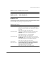
Table 2-1: PoS Module and Port LEDs (continued)
LED
Port x
Color
Indicates
up1
Corrective action
Green
Link
(No action required.)
Green blinking
Link disabled
See “Fixing Link Down
Problems” on page 2-15.
Amber blinking,
returning to green
Activity on link
(No action required.)
Amber blinking
Link down; SONET link problem See “Fixing Link Down
Problems” on page 2-15.
Off
No received signal
See “Fixing Link Down
Problems” on page 2-15.
1. The link is up, but the PPP/VLAN interface might not be up. To determine whether PPP is up, use the
show ppp command to display PPP status information (see the command description on page 3-27).
Fixing Configuration Errors
If the STATUS LED on the PoS module turns amber and blinks, use the show slot
command to display the configured slot type. The output from this command also
displays information about the module state, including the CARD MISMATCH
message. This message indicates that the slot was previously configured for a module
type different than the one you just installed.
Use one of the following commands to reset the slot configuration:
• clear slot <slot>
• unconfig slot <slot>
• config slot <slot> module [f32t | f32f | f48t | g4x | g6x | g8x |
g12x | p3c | p12c]
The first two commands listed above clear the slot of a previously assigned
module type. The third command replaces the existing module type configuration
with a new module type configuration.
Packet Over SONET Module Installation and User Guide
2-13
Installing or Replacing a PoS Module
Upgrading the Switch Software Image
If the STATUS LED on the PoS module turns amber and blinks, use the show slot
command to display the configured slot type. The output from this command also
displays information about the module state, including the CARD UNKNOWN
message. This message indicates that the installed ExtremeWare software image version
does not recognize the module type.
To correct this problem, you will need to upgrade the ExtremeWare software image. To
perform this task, see the “Software Upgrade and Boot Options” chapter in the
ExtremeWare Software User Guide.
Upgrading the PoS Module Software Image
The PoS module software image file contains the executable code that runs on the PoS
module. The image file is preinstalled on the PoS module at the factory. As new
versions of the image are released, they can be downloaded to the PoS module.
When you upgrade the PoS module software image, you might also be required
to upgrade the image for associated MSM modules to maintain software
compatibility.
To download a PoS software image, use the following command:
download image [<ipaddress> | <hostname>] <filename> {primary | secondary}
slot <slot>
This command is the same command used to download ExtremeWare images to MSM
modules, but you use the slot <slot> option to download the specified image file to
the PoS module in the specified slot rather than to one of the switch’s image partitions.
Like the MSM module, the PoS module can store up to two images: a primary and a
secondary image. When you download a new image, you must specify the image
space—primary or secondary—where the new image is to be stored. If you do not
specify the image space, the new image is downloaded to the image space that will be
used as the load source on the next reboot.
To select which image—primary or secondary—the PoS module will load on the next
reboot, use the following command:
use image [primary | secondary] slot <slot>
2-14
Packet Over SONET Module Installation and User Guide
Troubleshooting
Fixing Power-Related Problems
If the LEDs on all other modules are off, verify that the BlackDiamond 6800 series
switch is connected to an appropriate power source and is turned on.
If the LEDs on the new module are off, but the LEDs on other modules are on, try
ejecting and reseating the unpowered module. If the module still does not power up, it
is possible that the available system power is not sufficient to handle the power
requirements of the added module. To test this condition, temporarily eject another I/O
module to see whether that frees enough power to power up the new card. If it does,
you may need to upgrade the power supply configuration in this BlackDiamond 6800
series switch. For more information on system power configuration, see the
BlackDiamond 6800 Series Switch Hardware Installation Guide.
Fixing Link Down Problems
A flashing green port status LED can indicate the following conditions:
• Port is disabled.
• Port is not configured as a member of a VLAN.
To enable a port, use the following command:
enable ports <portlist>
To add a port to a VLAN, use the following command:
config vlan <name> add port <portlist> {tagged | untagged} {nobroadcast}
A flashing amber port status LED indicates that a signal has been detected, but that one
or more SONET alarms exist. Use the show sonet detail command to display SONET
status information.
If the port status LED is off, suspect a loss-of-signal condition caused by a optical-fiber
cable or connector problem. Check for one or more of the following conditions:
• The transmit (Tx) and receive (Rx) cable connectors are reversed in the module port
connector. Remove and reinsert the connectors in their correct positions.
• The optical-fiber cable is not terminated. Verify that the connectors on both ends of
the cable are plugged in correctly and firmly seated.
• The optical-fiber cable is damaged. Replace the cable with a cable known to be good
and try again.
Packet Over SONET Module Installation and User Guide
2-15
Installing or Replacing a PoS Module
Identifying Conditions for Replacing an I/O Module
If the STATUS LED on the PoS module turns amber and blinks, use the show slot
command to display the slot status information. If the output of the command shows
that the module state is not OPERATIONAL, use the following commands to run the
diagnostics on the module and display the results:
run diagnostics [normal | extended] <slot>
show diagnostics {<slot>}
The displayed results list each test that was run, and indicate whether that test passed
or failed. If the diagnostics fail, replace the PoS module with another module of the
same type.
After you run the diagnostics, you must use the reboot slot command to reset
the slot and reload the operational PoS module software image.
For more information about the slot diagnostics, see the “Status Monitoring and
Statistics” chapter in the ExtremeWare Software User Guide.
Removing and Replacing an I/O Module
I/O modules can be installed only in any of the BlackDiamond 6800 series chassis slots
labeled slots 1 through 8. I/O modules do not fit in slots A or B. Forceful insertion can
damage the I/O module.
I/O modules can be extracted from the BlackDiamond 6800 series chassis, or
inserted into the chassis at any time, without disrupting network services.
Tools and Equipment
You will need the following items to remove and replace an I/O module:
• ESD-preventive wrist strap and leash
• Number 1 Phillips-head screwdriver
• Replacement I/O module
2-16
Packet Over SONET Module Installation and User Guide
Removing and Replacing an I/O Module
Removing an I/O Module
To remove an I/O module, follow these steps:
1 Put on the ESD-preventive wrist strap that is provided with the chassis, and verify
that the metal end of the leash is connected to the ground receptacle located on the
top-left corner of the BlackDiamond 6800 series switch front panel.
2 Identify the I/O module to be replaced and write down the following information
for later use:
— The chassis slot number and the type of I/O module. When you install the
replacement I/O module, install it in the same chassis slot.
— The optical-fiber cable connections to the I/O module connectors. You must
reconnect the cables to the same connectors on the replacement I/O module.
3 Disconnect all of the optical-fiber cables from the I/O module and set them carefully
aside.
Be very careful in handling optical-fiber cables: kinks and sharp bends can
destroy or degrade the cable’s ability to convey light pulses accurately.
4 Use the #1 Phillips-head screwdriver to loosen the captive screw at each end of the
I/O module front panel.
5 Grasp both ejector/injector handles and pivot them simultaneously away from each
other to unseat the module from the chassis backplane.
6 Use the ejector/injector handles to pull the module part way out of the chassis slot.
Do not touch the printed circuit board or any connector pins.
There is an EMI-preventive gasket attached to one edge of the module front
panel. To prevent diminished EMI protection, handle the module carefully and
avoid damage to this gasket.
7 Grasp the module front panel with one hand and place your other hand under the
metal card carrier to support the weight of the module. Slide the module completely
out of the chassis slot. Place the module immediately into an antistatic sack to
protect it from ESD damage and prevent dust from collecting on the module’s
optical-fiber connectors.
8 Install and secure the replacement module as described in the “Inserting and
Securing a Module” on page 2-7.
9 Check your notes on the slot assignment and cable connection information that you
wrote down before removing the defective I/O module, then reconnect the network
interface cables to their assigned ports on the I/O module.
Packet Over SONET Module Installation and User Guide
2-17
Installing or Replacing a PoS Module
2-18
Packet Over SONET Module Installation and User Guide
3
Configuring the PoS Module
This chapter describes the ExtremeWare commands that support the PoS module. Other
commands and background information used to configure I/O modules and switch
behavior in a network are documented in the ExtremeWare Software User Guide. For
hardware installation information on the BlackDiamond 6800 series switch, see the
BlackDiamond Hardware Installation Guide.
Documentation for Extreme Networks products is available on the World Wide
Web at the Extreme Networks home page at http://www.extremenetworks.com/.
This chapter includes information on the following topics:
• Basic PoS Module Configuration Information on page 3-2
• Configuring and Monitoring SONET Ports on page 3-12
• Configuring and Monitoring PPP Functions on page 3-22
• Configuring VLAN-Related Attributes on page 3-38
• Configuring Forwarding Database Attributes on page 3-42
• Configuring Spanning Tree Attributes on page 3-42
• Configuring QoS Functions on page 3-43
• Configuring and Monitoring Flow Statistics on page 3-60
• Configuring and Monitoring APS Functions on page 3-75
• Configuring Port Tunneling on page 3-97
• Additional PoS Module Support Topics on page 3-101
Packet Over SONET Module Installation and User Guide
3-1
Configuring the PoS Module
Basic PoS Module Configuration Information
This section uses several typical usage and configuration schemes to provide a brief
overview of the PoS module configuration process as a general context for the detailed
command description sections that follow.
Default PoS Module Configurations
When the BlackDiamond 6800 series switch is powered on, the ExtremeWare software
determines which slots are occupied by I/O modules, determines whether it has a
configuration for each module, and generates a default configuration for each slot that
is occupied by an I/O module that has not yet been configured. The default
configuration is the minimal set of configuration parameter settings that will allow the
I/O module and its ports to function.
For the PoS modules, the default configuration depends on whether the module is an
OC-3 module (P3cSi or P3cMi) or an OC-12 module (P12cSi or P12cMi). The OC-3
modules have some port-pairing considerations that affect configuration (see “PoS Port
Configuration and Default VLAN Assignments” on page 3-3). In either case, the default
configuration on the PoS module is for bridging (see “Default Configuration: Bridging
Over PoS Ports” on page 3-3), with the Bridging Control Protocol (BCP) enabled, so that
the module’s ports are brought up as members of the default VLAN and traffic is
bridged between all ports in the VLAN. The default configuration includes values for
the configurable SONET link parameters.
To perform routing over PoS ports using the IP Control Protocol (IPCP), or to take
advantage of other features and capabilities, such as providing redundancy over the
tributary links of the SONET network using Automatic Protection Switching (APS), you
will need to perform additional configuration tasks. For examples of how to extend the
configuration, see “Routing Over PoS Ports” on page 3-6 and “Automatic Protection
Switching” on page 3-7.
3-2
Packet Over SONET Module Installation and User Guide
Basic PoS Module Configuration Information
PoS Port Configuration and Default VLAN Assignments
The ports on the PoS modules are identified by a port number that is a combination of
the slot number where the module is installed and the port number on the module. The
nomenclature for the port number is as follows:
slot:port
For example, you would refer to the four ports on an OC-3 PoS module installed in
slot 4 of the BlackDiamond 6800 series chassis by the port numbers 4:1, 4:2, 4:3, and 4:4.
For more information about port numbers and port configuration, see the
ExtremeWare Software User Guide.
Because the default Point-to-Point Protocol (PPP) network control protocol is the Bridge
Control Protocol (BCP), all PoS ports are initially enabled for bridging. By default, only
ports 1 and 3 on the OC-3 PoS modules are assigned to the default VLAN, while ports 2
and 4 are not assigned to a VLAN.
Because the first port pair on the OC-3 PoS modules (ports 1 and 2) and the second port
pair (ports 3 and 4) use a common link to the switch backplane, ports belonging to the
same port pair cannot be assigned to the same VLAN. The only exception to this rule is
when APS is defined and one of the two ports of a port pair is used as the working line
port, while the second port is used as the protection line port.
The port-pair restriction described above for the OC-3 PoS modules does not
apply to the OC-12 PoS module.
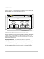
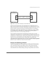
Default Configuration: Bridging Over PoS Ports
The default configuration of the OC-3 PoS module enables you to connect either port 1
or 3 (not both) of an OC-3 PoS module in a BlackDiamond 6800 series switch to either
port 1 or 3 of an OC-3 PoS module in a second BlackDiamond switch. In this
configuration, all ports reside in the default VLAN and traffic is bridged between all
ports in the VLAN. If you enable the Spanning Tree protocol, you can connect more
ports in parallel, but they will be blocked for traffic transmission. Loadsharing is not
supported over PoS links.
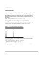
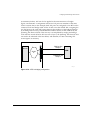
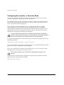
Configuration Commands for BCP
The bridged network example shown in Figure 3-1 does not require additional
configuration commands for BCP support, because the default SONET and PPP
Packet Over SONET Module Installation and User Guide
3-3
Configuring the PoS Module
configuration values will bring up the ports as members of the default VLAN.
However, the commands to enable BCP together with the default SONET values (see
Table 3-1) are listed below for reference. The command unconfig ppp ports
<portlist> will also reset these default values.
BlackDiamond 1
1
2
3
4
A
B
5
BlackDiamond 2
6
7
8
1
2
3
4
A
B
5
6
7
8
8:1
BCP
1:3
PoS_005
Figure 3-1: Default configuration for BCP
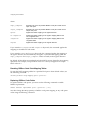
Configuring Default SONET and PPP Settings
The following configuration commands apply to the PoS module installed in slot 8 of
BlackDiamond switch 1, as shown in Figure 3-1.
config ppp echo 1 5 ports 8:1
config ppp authentication off ports 8:1
config ppp quality off ports 8:1
config ppp user "extreme" encrypted "f7P*8aPO+86+’RL8E?MDZBJV‘F)UC.-"
ports 8:1
config ppp bcp on ports 8:1
config ppp ipcp off ports 8:1
config ppp pos checksum 32 ports 8:1
config ppp pos scrambling on ports 8:1
config ppp delayed-down-time 1 ports 8:1
3-4
Packet Over SONET Module Installation and User Guide
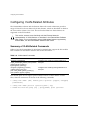
Basic PoS Module Configuration Information
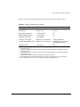
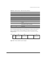
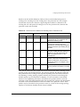
Table 3-1 lists the configurable SONET link parameters and their default values.
Table 3-1: SONET Parameters and Values
Parameter
Possible Values
Default Value
Framing
SONET or SDH
SONET
internal or line
internal
10-3
10-5
10-5
10-5 through 10-9
10-6
0 through 255
1
Maximum of 15 characters
15 NULL characters
Maximum of 64 characters
IP address of port’s VLAN (in
dotted-decimal notation)
0 through xFF
auto
Clock source
Signal Failure
threshold1
Signal Degrade threshold2
J0 Section Trace
byte3
J0 Section Trace
string4
J1 Path Trace identifier
string5
C2 Signal Label6
through
1. B2 bit error rate (BER) threshold; a Signal Failure (SF) event is generated if the BER exceeds the
specified threshold.
2. B2 bit error rate (BER) threshold; a Signal Degrade (SD) event is generated if the BER exceeds the
specified threshold.
3. The default value of 1 is per ANSI T1.105-1995. This parameter applies only when SONET framing is
configured on the port.
4. This parameter applies only when SDH framing is configured on the port.
5. When SDH framing is configured on the port, only the first 15 characters of the string are applied.
6. Set automatically based on synchronous payload envelope (SPE) payload type.
Packet Over SONET Module Installation and User Guide
3-5
Configuring the PoS Module
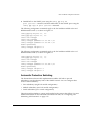
Routing Over PoS Ports
While you can configure BCP to perform routing over PoS ports, IPCP might be a better
choice than BCP in those cases where the link will carry only routed IP traffic, because
it provides a more efficient encapsulation scheme than does BCP, and thereby increases
the maximum link throughput.
To take best advantage of the wire-speed layer 3 routing capabilities of the
BlackDiamond 6800 series switch using the PoS module, configure IPCP as the PPP
network control protocol to route between the PoS ports and any other VLANs. If you
do not configure APS, an IPCP port must be the only port in a VLAN.
BlackDiamond 1
1
2
3
4
A
B
5
BlackDiamond 2
6
7
8
1
8:1 IPCP
1:1
8:2
1:3
IPCP
2
3
4
A
B
5
6
7
8
PoS_006
Figure 3-2: IPCP configuration
Configuration Commands for IPCP
For the IPCP routing network configuration example shown in Figure 3-2, the default
configuration parameter settings for PoS ports should be suitable for most installations.
Thus, only minimal additional configuration is needed to get IPCP up and running on a
PoS port. The necessary configuration steps are:
1 Create a VLAN for each SONET port using the create vlan <name> command.
2 Add each SONET port to a VLAN using the config vlan <name> add
ports <port> command.
3 Define an IP router port on each VLAN by assigning an IP address to each VLAN
using the config vlan <name> ipaddress <ipaddress> {<mask>} command,
and enable IF forwarding using the enable ipforwarding command.
3-6
Packet Over SONET Module Installation and User Guide
Basic PoS Module Configuration Information
4 Disable BCP on the SONET ports using the config ppp bcp off
ports <portlist> command, and then enable IPCP on the SONET ports using the
config ppp ipcp on ports <portlist> command.
The following configuration commands apply to the PoS module installed in slot 8 of
BlackDiamond switch 1, as shown in Figure 3-2.
config
config
create
create
config
config
enable
config
config
ppp bcp off ports 8:1, 8:2
ppp ipcp on ports 8:1, 8:2
vlan vlanipcp1
vlan vlanipcp2
vlanipcp1 ipaddress 192.168.100.1 /30
vlanipcp2 ipaddress 192.168.200.1 /30
ipforwarding
vlanipcp1 add ports 8:1
vlanipcp2 add ports 8:2
The following configuration commands apply to the PoS module installed in slot 1 of
BlackDiamond switch 2, as shown in Figure 3-2.
config
config
create
create
config
config
enable
config
config
ppp bcp off ports 1:1, 1:3
ppp ipcp on ports 1:1, 1:3
vlan vlanipcp1
vlan vlanipcp2
vlanipcp1 ipaddress 192.168.100.2 /30
vlanipcp2 ipaddress 192.168.200.2 /30
ipforwarding
vlanipcp1 add ports 1:3
vlanipcp2 add ports 1:1
Automatic Protection Switching
The ExtremeWare software APS implementation enables PoS links to provide
redundancy over the tributary links of the SONET network. You can configure three
levels of APS redundancy:
• Port redundancy (single PoS module configuration)
• Module redundancy (two PoS module configuration)
• Switch redundancy (two switch configuration)
These three APS redundancy options are described in the sections that follow. For more
detailed information on the commands associated with APS, see “Configuring and
Monitoring APS Functions” on page 3-75.
Packet Over SONET Module Installation and User Guide
3-7
Configuring the PoS Module
APS Port Redundancy
Figure 3-3 is an example of a single-module APS redundancy configuration, in which
the working line and the protection line are terminated in the same PoS module in the
BlackDiamond 6800 series switch. This configuration provides simple protection against
line failures.
Add-Drop
Multiplexer
(ADM)
BlackDiamond 1
1
2
3
4
A
B
5
6
7
8
BlackDiamond 2
1
2
3
4
A
B
5
6
7
8
8:1
(Working line)
8:2
(Protection
line)
SONET
ring
1:4
PoS_007
Figure 3-3: APS configuration, port redundancy
Configuration Commands for APS: Port Redundancy
The following configuration commands apply to the PoS module installed in slot 8 of
BlackDiamond switch 1, as shown in Figure 3-3.
create
config
enable
create
config
config
enable
3-8
vlan apslbvlan
vlan apslbvlan ipaddress 192.168.1.1 /30
loopback-mode apslbvlan
aps 1
aps 1 add 8:1 working
aps 1 add 8:2 protection 192.168.1.1
aps
Packet Over SONET Module Installation and User Guide
Basic PoS Module Configuration Information
APS Module Redundancy
Figure 3-4 is an example of a two-module APS redundancy configuration, in which the
working line and the protection line are terminated in two different PoS modules in the
same BlackDiamond 6800 series switch. This configuration provides simple protection
against both line and module failures.
BlackDiamond 1
1
2
3
4
A
B
5
BlackDiamond 2
6
7
8
1
8:1
(Working line)
2
3
4
A
B
5
6
7
8
ADM
SONET
ring
5:4
1:4
(Protection
line)
PoS_008
Figure 3-4: APS configuration, module redundancy
Configuration Commands for APS: Module Redundancy
The following configuration commands apply to the two PoS modules installed in
slots 5 and 8 of BlackDiamond switch 1, as shown in Figure 3-4.
create
config
enable
create
config
config
enable
vlan apslbvlan
apslbvlan ipaddress 192.168.1.1 /30
loopback-mode apslbvlan
aps 1
aps 1 add 8:1 working
aps 1 add 5:4 protection 192.168.1.1
aps
Packet Over SONET Module Installation and User Guide
3-9
Configuring the PoS Module
APS Switch Redundancy
Figure 3-5 is an example of a two-switch APS redundancy configuration, in which the
working line is terminated in a PoS module in one BlackDiamond switch, while the
protection line is terminated in a different PoS module in a different BlackDiamond
switch. This configuration expands protection to include line, module, and switch
failures.
BlackDiamond 1
1
2
3
4
A
B
BlackDiamond 2
5
6
7
8
1
2
3
4
A
B
5
6
7
8
ADM
8:1
(Working line)
SONET
ring
1:4
6:1
apsvlan
BlackDiamond 3
1
2
3
4
A
B
6:1
5
6
7
8
3:2
(Protection line)
PoS_009
Figure 3-5: APS configuration for switch redundancy
3-10
Packet Over SONET Module Installation and User Guide
Basic PoS Module Configuration Information
Configuration Commands for APS: Switch Redundancy
The following configuration commands apply to the PoS module installed in slot 8 of
BlackDiamond switch 1, as shown in Figure 3-5.
create vlan apsvlan
config apsvlan add port 6:1
config apsvlan ipaddress 192.168.1.1 /30
enable loopback-mode apsvlan
enable ipforwarding
create aps 1
configure aps 1 add 8:1 working
enable aps
The following configuration commands apply to the PoS module installed in slot 3 of
BlackDiamond switch 3, as shown in Figure 3-5.
create vlan apsvlan
configure apsvlan add port 6:1
configure apsvlan ipaddress 192.168.1.2 /30
enable ipforwarding
create aps 1
configure aps 1 add 3:2 protection 192.168.1.1
enable aps
Packet Over SONET Module Installation and User Guide
3-11
Configuring the PoS Module
Configuring and Monitoring SONET Ports
In addition to the ExtremeWare commands for configuring slot and port behavior that
are described in the ExtremeWare Software User Guide, this section describes the
commands used to configure SONET link attributes.
This section provides information on the following topics:
• Commands for Configuring and Monitoring SONET Ports on page 3-13
• Configuring SONET Framing on page 3-13
• Configuring SONET Clocking on page 3-14
• Configuring the Signal Fail Threshold on page 3-14
• Configuring the Signal Degrade Threshold on page 3-15
• Configuring the Section Trace Identifier on page 3-15
• Configuring the Path Trace Identifier on page 3-16
• Configuring the Signal Label on page 3-17
• Resetting SONET Configuration Parameter Values on page 3-17
• Displaying SONET Port Status Information on page 3-18
Table 3-1 on page 3-5 describes the configurable SONET link parameters and their
default values, Table 3-2 on page 3-13 describes the ExtremeWare commands for
configuring and monitoring SONET ports, Table 3-3 on page 3-18 lists the supported
SONET statistics, and Table 3-4 on page 3-19 describes the SONET events and their
associated actions.
3-12
Packet Over SONET Module Installation and User Guide
Configuring and Monitoring SONET Ports
Commands for Configuring and Monitoring SONET Ports
Table 3-2 describes the ExtremeWare commands for configuring and monitoring SONET
ports. Each command is described in detail in the sections that follow.
Table 3-2: SONET Port Commands
Command
Description
config sonet clocking [line | internal]
ports <portlist>
Configures the clocking source for the specified
SONET ports.
config sonet framing [sonet | sdh]
ports <portlist>
Configures the framing type for the specified
SONET ports.
config sonet signal label [auto | <hex_octet>] Configures the Signal Label value for the
ports <portlist>
specified SONET ports.
config sonet threshold signal degrade
<error_rate> ports <portlist>
Configures the Signal Degrade threshold for the
specified SONET ports.
config sonet threshold signal fail <error_rate> Configures the Signal Failure threshold for the
ports <portlist>
specified SONET ports.
config sonet trace path <id_string>
ports <portlist>
Configures the Path Trace Identifier string for the
specified SONET ports.
config sonet trace section [<id_byte> |
string <id_string>] ports <portlist>
Configures the Section Trace Identifier for the
specified SONET ports.
show sonet {<portlist>} {detail}
Displays SONET port status.
unconfig sonet ports <portlist>
Resets the configuration parameters of the
specified SONET ports to their default values.
Configuring SONET Framing
You can configure each port for framing that complies with either the SONET standard
or the SDH standard. SONET is primarily an American standard; SDH is the
international version. The default is SONET.
To configure the framing for the specified SONET port, use the following command:
config sonet framing [sonet | sdh] ports <portlist>
The following command example selects SDH framing for port 1 of the PoS module
installed in slot 8 of the BlackDiamond switch.
config sonet framing sdh ports 8:1
Packet Over SONET Module Installation and User Guide
3-13
Configuring the PoS Module
Configuring SONET Clocking
You can configure each port on the PoS module to use either line clocking, where the
clock source is recovered from the received bit stream, or internal clocking, where the
clock source is based on an internal clock. The default is internal.
To configure the clocking source for the specified SONET port, use the following
command:
config sonet clocking [line | internal] ports <portlist>
The following command example selects line clocking for port 1 of the PoS module
installed in slot 8 of the BlackDiamond switch.
config sonet clocking line ports 8:1
Configuring the Signal Fail Threshold
A Signal Failure (SF) event is generated if the bit error rate (BER) for the SONET line
exceeds the configured threshold. An SF event brings the port down. If Automatic
Protection Switching (APS) is enabled on the port, an SF event initiates a line switch.
To configure the Signal Fail threshold for the specified SONET port, use the following
command:
config sonet threshold signal fail <error_rate> ports <portlist>
The error_rate parameter is an integer in the range from 3 to 5, where the SF BER is
10-error_rate. The default value of the error_rate parameter is 5, which equates to an SF
bit error rate of 10-5, or 1 per hundred thousand.
The following command example sets the Signal Fail threshold value to 3 for port 1 of
the PoS module installed in slot 8 of the BlackDiamond switch.
config sonet threshold signal fail 3 ports 8:1
You might set the signal fail threshold lower than the default value of 5 if your
particular application has a very low tolerance for errors. In general, you should
not change the default setting unless you are an expert and have a specific
reason for the change.
3-14
Packet Over SONET Module Installation and User Guide
Configuring and Monitoring SONET Ports
Configuring the Signal Degrade Threshold
A Signal Degrade (SD) event is generated if the BER for the SONET line exceeds the
configured Signal Degrade threshold. If APS is enabled on the port, an SD event
initiates a line switch.
To configure the Signal Degrade threshold for the specified SONET port, use the
following command:
config sonet threshold signal degrade <error_rate> ports <portlist>
The error_rate parameter is an integer in the range from 5 to 9, where the SD bit error
rate is 10-error_rate. The default value of the error_rate parameter is 6, which equates to
an SD bit error rate of 10-6, or 1 per million.
The following command example sets the Signal Degrade threshold value to 8 for port 1
of the PoS module installed in slot 8 of the BlackDiamond switch.
config sonet threshold signal degrade 8 ports 8:1
You might set the signal degrade threshold to a different value than the default
value of 6 depending on your particular application’s tolerance for errors. In
general, you should not change the default setting unless you are an expert and
have a specific reason for the change.
Configuring the Section Trace Identifier
Section trace is a maintenance feature of SONET. One byte of the Section Overhead
associated with each SONET frame is used to carry information identifying the
transmitting equipment.
To configure the Section Trace identifier for the specified SONET port, use the following
command:
config sonet trace section [<id_byte> | string <id_string>] ports <portlist>
In this command, the Section Trace identifier can take one of two forms: an ID byte
(id_byte) or an ID string (id_string).
The id_byte parameter is an integer in the range from 1 to 255, with a default value
of 1. This parameter applies only when SONET framing is configured, in which case,
the configured id_byte value is transmitted in each SONET frame.
Packet Over SONET Module Installation and User Guide
3-15
Configuring the PoS Module
The id_string parameter is a string of up to 15 characters. By default, the <id_string>
parameter contains 15 NULL characters. This parameter applies only when SDH
framing is configured, in which case the SDH framing cycles repetitively through a
15-character string, sending one character per frame. If the configured string contains
fewer than 15 characters, it is padded to full length by NULL characters.
The following command example sets the Section Trace identifier to the string
“1800wombat” for port 1 of the PoS module installed in slot 8 of the BlackDiamond
switch.
config sonet trace section string 1800wombat ports 8:1
Configuring the Path Trace Identifier
Path trace is a maintenance feature of SONET. One byte of the Path Overhead
associated with each SONET frame is used to carry information identifying the
originating Path Terminating Equipment (PTE).
To configure the Path Trace identifier for the specified SONET port, use the following
command:
config sonet trace path <id_string> ports <portlist>
The id_string parameter is a string of up to 64 characters. By default, the id_string
parameter contains the IP address assigned to the VLAN to which the port belongs.
This IP address is represented in dotted-decimal notation. If no IP address is assigned to
the port’s VLAN, the id_string parameter defaults to a string of 64 NULL characters.
When SONET framing is configured, a 64-character string is transmitted repetitively,
one character per frame. If the configured string consists of fewer than 64 characters, it
is padded to its full length with NULL characters.
When SDH framing is configured, the maximum length of the id_string parameter is
15 characters. If the configured string consists of more than 15 characters, it is truncated
to 15 characters.
The following command example sets the Path Trace identifier to the string “parador”
for port 1 of the PoS module installed in slot 8 of the BlackDiamond switch.
config sonet trace path parador ports 8:1
3-16
Packet Over SONET Module Installation and User Guide
Configuring and Monitoring SONET Ports
Configuring the Signal Label
The Signal Label field occupies one byte (C2) of the Path Overhead associated with each
SONET frame. It is used to indicate the type of contents carried in the Synchronous
Payload Envelope (SPE). For example, 0x16 indicates scrambled PPP/HDLC, while
0xCF indicates unscrambled PPP/HDLC.
To configure the C2 Signal Label value for the specified SONET port, use the following
command:
config sonet signal label [auto | <hex_octet>] ports <portlist>
The value parameter is specified as a hexadecimal integer in the range from 00 to FF. It
may be necessary to specify a particular Signal Label value in order to interoperate with
implementations that do not follow the standard conventions for the Signal Label field.
To determine whether you need to specify a particular Signal Label value, perform the
following tasks:
1 Use the show sonet command to display SONET port status information.
2 Look for a Path Payload Label Mismatch (PLM-P) event indicating that the received
payload type does not match the expected payload.
3 Compare the contents of the received C2 field (Signal Label value) with the contents
of the transmitted C2 field.
If no Signal Label value is specified, the command defaults to auto, which causes the
value of the Signal Label field to be set automatically based on standard conventions for
the given payload type.
The following command example sets the Signal Label to the hexadecimal value CF for
port 1 of the PoS module installed in slot 8 of the BlackDiamond switch.
config sonet signal label CF ports 8:1
Resetting SONET Configuration Parameter Values
To reset the SONET configuration parameters for the specified SONET ports to their
default values, use the following command:
unconfig sonet ports <portlist>
Packet Over SONET Module Installation and User Guide
3-17
Configuring the PoS Module
Displaying SONET Port Status Information
To display status information for the SONET ports, use the following command:
show sonet {<portlist>} {detail}
You can use the optional portlist parameter to narrow the range of status information
the command displays; otherwise, the command displays the status information for all
ports.
By default, the command displays a summary of status information for the specified
ports. You can use the optional detail keyword to display detailed status information
for the specified ports.
The summary of status information includes the following information for each port:
• Values of all port configuration parameters
• Port state
• Any active events
The detailed status information includes the summary information plus any SONET
statistics (listed and described in Table 3-3).
Table 3-3: Summary of SONET Statistics
Statistic
Description
Section parity errors
Number of B1 parity errors detected
Line parity errors
Number of B2 parity errors detected
Path parity errors
Number of B3 parity errors detected
REI-L event counter
Number of B2 parity errors detected by peer LTE
REI-P event counter
Number of B3 parity errors detected by peer PTE
LOS event counter
Number of LOS events
LOF event counter
Number of LOF events
LOP event counter
Number of LOP events
AIS-L event counter
Number of AIS-L events
AIS-P event counter
Number of AIS-P events
RDI-L event counter
Number of RDI-L events
RDI-P event counter
Number of RDI-P events
3-18
Packet Over SONET Module Installation and User Guide
Configuring and Monitoring SONET Ports
Table 3-3: Summary of SONET Statistics (continued)
Statistic
Description
PLM-P event counter
Number of PLM-P events
SF BER event counter
Number of SF BER events
SD BER event counter
Number of SD BER events
SONET Events
The PoS module can detect and report a variety of error and alarm conditions, some of
which also trigger actions on the SONET link. Table 3-4 describes these events and their
associated actions. Syslog messages are output for these events.
Table 3-4: SONET Events
Event
Description
Loss of Signal (LOS)
Loss of Signal is detected by the Section Terminating Equipment
(STE) when an all-zeroes pattern on the incoming SONET signal
lasts 100 microseconds or longer. This condition can be caused by
loss of light.
SONET Action: Send RDI-L upon LOS detection.
Loss of Frame (LOF)
Loss of Frame is detected by the STE when a Severely Errored
Framing (SEF) defect on the incoming signal persists for 3
milliseconds.
Related SONET Overhead: A1, A2 (framing pattern).
SONET Action: Send RDI-L upon LOF detection.
Loss of Pointer (LOP)
The Path Loss Of Pointer event is detected as a result of excess
New Data Flags (NDFs) or invalid pointers in the H1/H2 fields of the
received signal.
Related SONET Overhead: H1,H2 contain NDF and pointer.
SONET Action: Send RDI-P upon LOP detection.
Alarm Indication
Signal—Line (AIS-L)
The Line Alarm Indication Signal is sent by the upstream STE to
inform the LTE that a LOS or LOF defect has been detected.
Extreme's SONET module never sends AIS-L. AIS-L was formerly
known as Line Far End Receive Failure (FERF).
Related SONET Overhead: K2 carries AIS-L.
SONET Action: Send RDI-L upon reception of AIS-L.
Packet Over SONET Module Installation and User Guide
3-19
Configuring the PoS Module
Table 3-4: SONET Events (continued)
Event
Description
Alarm Indication
Signal—Path (AIS-P)
The Path Alarm Indication Signal is sent by the upstream LTE to
inform the PTE that a LOS, LOF, AIS-L, or LOP defect has been
detected. Extreme's SONET module never sends AIS-P. AIS-P was
formerly known as Path Far End Receive Failure (FERF).
Related SONET Overhead: H1,H2,H3 = 0 when indicating AIS-P.
SONET Action: Send RDI-P upon receiving AIS-P.
Remote Defect
Indicator—Line (RDI-L)
The Line Remote Defect Indication is sent by the downstream LTE
when a LOS, LOF, or AIS-L defect is detected.
Related SONET Overhead: K2 carries RDI-L.
Remote Defect
Indicator—Path (RDI-P)
The Path Remote Defect Indication is sent by the downstream PTE
when a LOP or AIS-P defect is detected.
Related SONET Overhead: G1 carries RDI-P.
Remote Error
Indicator—Line (REI-L)
The Line Remote Error Indicator conveys a count of detected B2
parity errors from the peer LTE.
Related SONET Overhead: M1 carries REI-L.
Remote Error
Indicator—Path (REI-P)
The Path Remote Error Indicator conveys a count of detected B3
parity errors from the peer PTE.
Related SONET Overhead: G1 carries REI-P.
Path Payload Label
Mismatch (PLM-P)
The Path Payload Label Mismatch event occurs when the received
payload type does not match the expected payload. This event is
commonly caused by a Signal Label or scrambling mode mismatch
configuration error.
Related SONET Overhead: C2 carries the Signal Label.
Signal Failure Bit Error
Rate (SF BER)
The Signal Failure BER event occurs when the B2 bit error rate
exceeds the configured SF threshold. This event is used for APS
switching.
Related SONET Overhead: B2 carries line parity.
SONET Action: Send RDI-L upon detecting SF BER event.
Signal Degrade Bit Error
Rate (SD BER)
The Signal Degrade BER event occurs when the B2 bit error rate
exceeds the configured SD threshold. This event is used for APS
switching.
Related SONET Overhead: B2 carries line parity.
3-20
Packet Over SONET Module Installation and User Guide
Configuring and Monitoring SONET Ports
Table 3-4: SONET Events (continued)
Event
Description
Automatic Protection
Switching (APS)
An APS event occurs when the value of K1 or K2 changes. This
event is an input to the APS state machine, which is responsible for
handling the event and outputting the appropriate syslog message.
The LOS, LOF, AIS-L, SF BER, and SD BER events are also input to
the APS state machine.
Related SONET Overhead: K1,K2
Packet Over SONET Module Installation and User Guide
3-21
Configuring the PoS Module
Configuring and Monitoring PPP Functions
In addition to the ExtremeWare commands for configuring slot and port behavior that
are described in the ExtremeWare Software User Guide, this section describes the
commands you use to configure PPP attributes for PoS module ports.
This section provides information on the following topics:
• PPP Background Information on page 3-22
• Commands for Configuring and Monitoring PPP Functions on page 3-26
• Configuring the PoS Checksum on page 3-27
• Configuring PoS Scrambling on page 3-27
• Configuring Link Maintenance on page 3-28
• Configuring PPP Link Quality Monitoring on page 3-29
• Configuring PPP Authentication on page 3-30
• Configuring the Name and Password for the Port on page 3-30
• Creating an Authentication Database Entry on page 3-31
• Configuring the Network Control Protocol on page 3-33
• Configuring the MPLS Control Protocol on page 3-34
• Configuring the Delayed-Down-Time Interval on page 3-35
• Displaying PPP Information on page 3-36
• Resetting PPP Configuration Parameter Values on page 3-37
Table 3-5 on page 3-26 describes the ExtremeWare commands you use to configure and
monitor PPP functions.
PPP Background Information
The Point-to-Point Protocol (PPP) encompasses a suite of protocols designed to provide
standard methods for transporting datagrams over point-to-point links. The use of PPP
over SONET links is commonly referred to as Packet over SONET, or PoS. The Extreme
Networks implementation of PPP for the PoS module provides support for the
following protocols in the PPP suite:
• Link Control Protocol (LCP)
• Link Quality Report (LQR) Protocol
3-22
Packet Over SONET Module Installation and User Guide
Configuring and Monitoring PPP Functions
• Challenge Handshake Authentication Protocol (CHAP)
• Password Authentication Protocol (PAP)
• IP Control Protocol (IPCP)
• Bridging Control Protocol (BCP)
• MultiProtocol Label Switching Control Protocol (MPLSCP)
• Extreme Discovery Protocol Control Protocol (EDPCP)
Link Control Protocol. The Link Control Protocol (LCP) establishes a logical
connection with the peer LCP entity through an exchange of configuration packets.
Data traffic cannot flow over the SONET link until LCP has successfully established this
connection. LCP is also responsible for negotiating options that are independent of
particular network layer protocols, such as the Quality Report, Authentication Protocol,
and Maximum Receive Unit options.
Quality Protocol Configuration Option. The LCP Quality Protocol configuration
option can be used to specify the use of the Link Quality Report (LQR) Protocol to
monitor the quality of the SONET link. If the LQR Protocol detects that the quality of
the link is less than a configured threshold, all network layer protocols running over the
link are brought down. This process of determining data loss and link viability is
referred to as Link Quality Monitoring (LQM).
Link Maintenance Configuration Option. In addition to the LQR option, the Extreme
Networks implementation of PPP also provides a Link Maintenance configuration
option. When link maintenance is enabled on a port and that port is not receiving data
packets, the link maintenance facility periodically transmits LCP echo-request packets. If
an echo-reply is not received within a configured interval, LCP brings the link down.
Authentication Protocols. The Extreme Networks implementation of PPP uses the
Challenge Handshake Authentication Protocol (CHAP) and the Password
Authentication Protocol (PAP) to authenticate peer network elements. PAP is a simple
protocol based on a clear-text user name and password pair, while CHAP is a stronger
authentication protocol that uses the Message Digest, Version 5 (MD5) one-way hash
algorithm. In the use of either protocol, if authentication fails, the connection with the
peer is terminated.
IP Control Protocol. IPCP is a member of a family of Network Control Protocols
(NCPs) defined for use with PPP. IPCP establishes and configures a connection to
transport IP datagrams efficiently across a PPP link between two routers. When IPCP is
Packet Over SONET Module Installation and User Guide
3-23
Configuring the PoS Module
enabled on a PoS port, all data forwarded over the SONET link must be routed by the
BlackDiamond 6800 series switch, as illustrated in Figure 3-6.
1
2
3
4
A
B
5
6
7
8
IP Router
192.168.9.1
192.168.10.1
VLAN a
Ethernet
port 1
Ethernet
port n
192.168.11.1
VLAN x
VLAN y
PPP-IPCP
PoS
port 1
PPP-IPCP
PoS
port n
PoS_021
Figure 3-6: View of logical connectivity to PoS ports with IPCP enabled
Generally, when IPCP is enabled on a port, the port must be a member of one and only
one VLAN. Furthermore, no other ports may be members of this VLAN, and IP routing
is the only protocol supported on the VLAN. The one exception to this rule occurs
when APS is enabled. A single VLAN may contain two IPCP-enabled ports if they are
members of the same APS group.
Bridging Control Protocol. BCP establishes and configures a connection for
transporting Ethernet MAC frames across a PPP link. The BCP link must be established
successfully before data traffic can flow over the link. Because BCP carries Ethernet
MAC frames, any protocol can be transported across a BCP connection. In a simplified
sense, BCP allows the PoS link to appear as an Ethernet LAN segment to the rest of the
switch, so BCP makes it possible for LAN services to be extended transparently across
SONET wide-area networks. Therefore, the port can be a member of multiple VLANs,
and frames can be either bridged or routed onto the link, as illustrated in Figure 3-7.
3-24
Packet Over SONET Module Installation and User Guide
Configuring and Monitoring PPP Functions
1
2
3
4
A
B
5
6
7
8
IP Router
192.168.9.1
192.168.10.1
VLAN x
Ethernet
port 1
PPP-BCP
PoS
port 1
VLAN y
PPP-BCP
PoS
port 3
PPP-BCP
PoS
port n
PoS_022
Figure 3-7: View of logical connectivity to PoS ports with BCP enabled
As Figure 3-7 shows, PoS ports 1 and 3 are bridged together along with Ethernet port 1
to form VLAN x, PoS port 3 belongs to both VLAN x and VLAN y, and routed
connectivity exists between VLAN x and VLAN y.
BCP is defined in RFC 2878, which was recently approved by the IETF as an update to
RFC 1638. Two features of the updated version are: support for IEEE 802.1Q VLANs,
and inline management. The VLAN support enables a BCP entity to advertise its ability
to accept frames containing a VLAN tag. Inline management refers to the capability of
transporting the Spanning Tree Protocol and other bridge management protocols inline
using the Bridged Data PPP Protocol ID (previously, RFC 1638 specified that Spanning
Tree Protocol messages be transported using a unique PPP Protocol ID). Extreme’s
implementation supports these features as specified in the new RFC.
MultiProtocol Label Switching Control Protocol. MPLSCP establishes and
configures a connection for transporting MPLS labeled frames across a PPP link. The
MPLSCP connection must be established successfully before data traffic can flow over
the link. Only unicast MPLS labeled packets are supported. Multicast MPLS labeled
packets are discarded by the PoS port.
Packet Over SONET Module Installation and User Guide
3-25
Configuring the PoS Module
MPLSCP is not explicitly configured on a PoS port. Rather, MPLSCP is automatically
enabled on a PoS port when the port is configured for IPCP, and MPLS is enabled on
the VLAN that the PoS port is a member of. When MPLSCP is enabled on a PoS port,
the port will transport IP and MPLS labeled packets, and the port must be a member of
one and only one VLAN. Furthermore, no other ports may be members of this VLAN,
and IP routing is the only protocol supported on the VLAN. The one exception to this
rule occurs when APS is enabled. A single VLAN may contain two IPCP-enabled ports
if they are members of the same APS group.
Extreme Discovery Protocol Control Protocol. EDPCP supports the exchange of
EDP control packets across PoS links. EDP is used to gather information about
neighboring Extreme switches, and to exchange topology information. EDPCP uses PPP
protocol ID 0x820D; EDP packets use PPP protocol ID 0x020D. These PPP protocol IDs
were assigned by the Internet Assigned Numbers Authority (IANA). When the PPP
peer is from a vendor other than Extreme, EDPCP is disabled on the link.
Commands for Configuring and Monitoring PPP Functions
Table 3-5 describes the ExtremeWare commands you use to configure and monitor PPP
functions. Each command is described in detail in the sections that follow.
Table 3-5: PPP Commands
Command
Description
config ppp [bcp [on | off] |
ipcp [on {peer-ipaddress <ipaddress>} | off]]
ports <portlist>
Configures the Network Control Protocol that will
run on the specified PPP ports.
config ppp authentication [off | chap | pap |
chap-pap] ports <portlist>
Configures authentication on the specified PPP
ports.
config ppp delayed-down-time <seconds>
ports <portlist>
Configures the delayed-down-time interval used
by PPP for the specified ports.
config ppp echo [<seconds>
<consecutive_misses> | off] ports <portlist>
Configures the link maintenance protocol on the
specified ports.
config ppp pos checksum [32 | 16]
ports <portlist>
Configures the size of the HDLC Frame Check
Sequence (FCS) to be used on the specified
SONET ports.
config ppp pos scrambling [on | off]
ports <portlist>
Specifies whether the payload data should be
scrambled on the specified SONET ports.
config ppp quality [off |
<required_percent> {<seconds>}]
ports <portlist>
Configures the Link Quality Monitoring (LQM)
protocol on the specified ports.
3-26
Packet Over SONET Module Installation and User Guide
Configuring and Monitoring PPP Functions
Table 3-5: PPP Commands (continued)
Command
Description
config ppp user <name> {encrypted}
{<password>} ports <portlist>
Configures the user name and password that the
specified PPP ports use in the event the PPP
peer requests authentication.
show ppp {<portlist>} {detail}
Displays status information for PPP ports.
unconfig ppp ports <portlist>
Resets the PPP configuration parameters for the
specified ports to their default values.
The following command is an enhanced application of the existing ExtremeWare
create account command. The pppuser keyword is used to specify the name of a
local database entry that is used to authenticate PPP peers.
create account pppuser <name> {encrypted} {<password>}
The PPP use of this command is described in “Creating an Authentication Database
Entry” on page 3-31.
Configuring the PoS Checksum
To configure the size of the HDLC Frame Check Sequence (FCS) to be used on the
specified SONET port, use the following command:
config ppp pos checksum [32 | 16] ports <portlist>
Choose either the 32-bit FCS or the 16-bit FCS. A 32-bit FCS is the default. RFC 2615
recommends the use of the 32-bit FCS.
For OC-3 applications, RFC 2615 allows the use of a 16-bit FCS, but
recommends using a 32-bit FCS. You should limit your use of the 16-bit FCS to
supporting interoperability with equipment that does not support the 32-bit FCS.
The following command example sets the FCS to 16 for port 1 of the PoS module
installed in slot 8 of the BlackDiamond switch.
config ppp pos checksum 16 ports 8:1
Configuring PoS Scrambling
To enable or disable payload data scrambling on the specified port, use the following
command:
Packet Over SONET Module Installation and User Guide
3-27
Configuring the PoS Module
config ppp pos scrambling [on | off] ports <portlist>
Choose either on or off. Scrambling is enabled by default.
RFC 2615 recommends that the SONET payload be scrambled. The option of disabling
scrambling is provided for backward compatibility with an earlier PoS standard.
Scrambling was introduced in RFC 2615 to alleviate potential security problems where
malicious users might intentionally generate packets with bit patterns that create
SONET synchronization problems.
The following command example turns off the scrambling function for port 1 of the PoS
module installed in slot 8 of the BlackDiamond switch.
config ppp pos scrambling off ports 8:1
Configuring Link Maintenance
The Extreme Networks implementation of PPP provides a link maintenance
configuration option. When link maintenance is enabled on a port and that port is not
receiving data packets, the link maintenance facility periodically transmits Link Control
protocol (LCP) echo-request packets. If an echo-reply is not received within a
configured interval, LCP brings the link down.
To enable the link maintenance protocol on a specified PPP port, use the following
command:
config ppp echo [<seconds> <consecutive_misses> | off] ports <portlist>
The seconds parameter is an integer in the range from 1 to 300 that specifies the period
between transmissions of echo-request packets.
The consecutive_misses parameter is an integer in the range from 1 to 100 that
determines how long PPP waits for a reply. If an echo-reply is not received within an
interval of duration (consecutive_misses * seconds) seconds, the link is brought down.
When APS is enabled on a SONET port, link maintenance should also be enabled on
that port.
The link maintenance protocol is off by default. If you enable link maintenance, the
recommended seconds value is 3, and the recommended consecutive_misses value is
10.
3-28
Packet Over SONET Module Installation and User Guide
Configuring and Monitoring PPP Functions
The following example enables link maintenance on port 1 of a PoS module in slot 8
and sets seconds to 3 and consecutive misses to 10.
config ppp echo 3 10 ports 8:1
Configuring PPP Link Quality Monitoring
The Link Control Protocol (LCP) establishes a logical connection with the peer LCP
entity through an exchange of configuration packets. Data traffic cannot flow over the
SONET link until LCP has successfully established this connection. LCP also allows the
negotiation of a quality monitoring protocol to monitor the viability of the PPP link on
a continuous basis. This process of determining data loss and link viability is referred to
as Link Quality Monitoring (LQM).
The LQM protocol uses the Link Quality Report (LQR) packet as a mechanism in the
test of the PPP link. The LQM protocol periodically transmits LQR packets containing
counts of packets and octets that have been transmitted and successfully received. This
information enables the LQM protocol to determine the percentage of data that is being
dropped due to poor link quality. If the drop percentage is greater than a configured
threshold, all network-layer protocols are brought down. Bringing a poor-quality link
down may be desirable when an alternate network path exists, or when billing is based
on the amount of data transmitted. By default, LQM is off.
To enable the LQM protocol on a specified PPP port, use the following command:
config ppp quality [off | <required_percent> {<seconds>}] ports <portlist>
The required_percent parameter is an integer in the range from 1 to 99 that is used to
determine the drop percentage threshold, where:
drop percentage threshold = (100–<required_percent>).
The optional seconds parameter is an integer in the range from 1 to 300. This parameter
value determines how often quality reports should be received from the peer LQR
entity. If you do not specify a value for the seconds parameter, the command uses the
default value of 30 seconds.
It can take up to seven reporting intervals for LCP to bring a link down. If the link
quality improves subsequent to being brought down, LCP automatically brings the link
back up. This type of service restoration takes a minimum of seven reporting intervals.
Packet Over SONET Module Installation and User Guide
3-29
Configuring the PoS Module
The following example enables the LQM protocol on port 1 of a PoS module in slot 3
and sets required_percent to 95. Because no value is specified for the optional
seconds parameter, the command uses the default of 30 seconds.
config ppp quality 95 ports 3:1
Configuring PPP Authentication
The Extreme Networks implementation of PPP uses the Challenge Handshake
Authentication Protocol (CHAP) and the Password Authentication Protocol (PAP) to
authenticate peer network elements. PAP is a simple protocol based on a clear-text user
name and password pair, while CHAP is a stronger authentication protocol that uses
the Message Digest, Version 5 (MD5) one-way hash algorithm. In the use of either
protocol, if authentication fails, the connection with the peer is terminated.
To configure authentication on a specified PPP port, use the following command:
config ppp authentication [off | chap | pap | chap-pap] ports <portlist>
The default is authentication off, meaning the peer is not authenticated.
When you configure authentication using the chap keyword, the peer is authenticated
using CHAP.
When you configure authentication using the pap keyword, the peer is authenticated
using PAP.
When you configure authentication using the chap-pap keyword, a request is made to
authenticate the peer using CHAP, but PAP may be used if the peer does not support
CHAP.
The following command example turns on CHAP authentication for port 1 of the PoS
module installed in slot 8 of the BlackDiamond switch.
config ppp authentication chap ports 8:1
Configuring the Name and Password for the Port
In the event a PPP peer requests authentication, the Extreme Networks implementation
of PPP responds to the peer’s CHAP or PAP authentication requests regardless of
whether the port is configured to authenticate the peer.
3-30
Packet Over SONET Module Installation and User Guide
Configuring and Monitoring PPP Functions
To configure the name and password for a specified PPP port, use the following
command:
config ppp user <name> {encrypted} {<password>} ports <portlist>
The name and password parameters can contain a maximum of 32 alphanumeric
characters each. As an option, you can use double quotation characters as delimiters to
enclose the name and password parameters.
If you do not specify a password parameter in this command, the command prompts
you to enter the new password two times: the first time to set the new password; the
second time to confirm the password.
The factory default value for both the name and password parameters is the word
extreme.
You should not attempt to use the encrypted keyword. It is used by the switch
when generating an ASCII configuration.
The following command example sets the name to “titus” and sets the password to
“1Afortune” for port 1 of the PoS module installed in slot 8 of the BlackDiamond
switch.
config ppp user "titus" "1Afortune" ports 8:1
Creating an Authentication Database Entry
Responses to authentication requests include a username. When the requesting entity
receives a response, it searches its local database for an entry with the specified
username. When an entry is located, the associated password is used to validate the
authentication response.
To create a local database entry that can be used to authenticate a PPP peer, use the
following command:
create account pppuser <name> {encrypted} {<password>}
The name and password parameters are both character strings of up to 32 alphanumeric
characters. Both strings must start with an alphabetic character, but can be any
combination of alphanumerical characters thereafter. As an option, you can use double
quotation characters as delimiters to enclose the name and password parameters.
Packet Over SONET Module Installation and User Guide
3-31
Configuring the PoS Module
If you do not specify a password string in this command, the command prompts you to
enter the password two times: the first time to set the string; the second time to confirm
it.
You should not attempt to use the encrypted keyword. It is used by the switch
when generating an ASCII configuration.
The following command example sets the authentication database name to “stretch”
and sets the password to “baserunner” for port 1 of the PoS module installed in slot 8 of
the BlackDiamond switch.
create account pppuser "stretch" "baserunner" ports 8:1
3-32
Packet Over SONET Module Installation and User Guide
Configuring and Monitoring PPP Functions
Configuring the Network Control Protocol
The Network Control Protocol is configured on a per-port basis, meaning that different
ports on the same module can be running either the Bridging Control Protocol (BCP) or
the IP Control Protocol (IPCP)—both protocols cannot be configured at the same time
on any port.
Generally, when IPCP is configured on a port, that port must be a member of a single
VLAN. Further, no other ports on this switch can be members of this VLAN, and IP
routing is the only protocol supported on this VLAN. The one exception to this rule is
when Automatic Protection Switching (APS) is enabled. In which case, a single VLAN
may contain two ports configured for IPCP if they are both members of the same APS
group.
For more information about setting up VLANs, see the ExtremeWare Software
User Guide.
BCP establishes and configures a connection for transporting Ethernet MAC frames
across a PPP link. Because BCP carries Ethernet MAC frames, any protocol can be
transported across a BCP connection. In a simplified sense, BCP allows the PoS link to
appear as an Ethernet LAN segment to the rest of the switch, so BCP makes it possible
for LAN services to be extended transparently across SONET wide-area networks.
Therefore, the port can be a member of multiple VLANs, and frames can be either
bridged or routed onto the link.
Generally, most of the switch capabilities provided for Ethernet ports are also available
for PoS ports configured for BCP. One exception is that there are restrictions on which
OC-3 PoS module ports can be bridged together (be configured as members of the same
VLAN). Ports 1 and 2 on the same OC-3 PoS module cannot be bridged together, and
ports 3 and 4 on the same OC-3 PoS module cannot be bridged together—unless they
are members of the same APS group. There are no such restrictions on OC-12 PoS
module ports.
To configure the Network Control Protocol for a specified PPP port, use the following
command:
config ppp [bcp [on | off] | ipcp [on {peer-ipaddress <ipaddress>} | off]]
ports <portlist>
By default, BCP is enabled on all PoS ports. BCP cannot be configured on a port unless
IPCP is off; IPCP cannot be configured on a port unless BCP is off.
Packet Over SONET Module Installation and User Guide
3-33
Configuring the PoS Module
When used with IPCP, the optional peer-ipaddress keyword and parameter value
provides a way to configure the IP address of the peer router. This capability is useful
with peer routers that do not advertise their IP address through the IPCP IP-Address
configuration option. If the peer router does advertise an IP address through IPCP, the
configured value for peer-ipaddress is ignored.
The following command example turns IPCP off and BCP on for port 1 of the PoS
module installed in slot 8 of the BlackDiamond switch.
config ppp ipcp off port 8:1
config ppp bcp on port 8:1
Configuring the MPLS Control Protocol
MPLSCP establishes and configures a connection for transporting MPLS labeled frames
across a PPP link. The MPLSCP connection must be established successfully before
MPLS labeled data traffic can flow over the link. Only unicast MPLS labeled packets are
supported. Multicast MPLS labeled packets are discarded by the PoS port.
MPLSCP is not explicitly configured on a PoS port. However, MPLSCP is automatically
enabled on a PoS port when the port is configured for IPCP and MPLS is enabled on
the VLAN that the PoS port is a member of. When MPLSCP is enabled on a PoS port,
the port will transport IP and MPLS labeled packets, and the port must be a member of
one and only one VLAN. Furthermore, no other ports may be members of this VLAN,
and IP routing is the only protocol supported on the VLAN. The one exception to this
rule occurs when APS is enabled. A single VLAN may contain two IPCP-enabled ports
if they are members of the same APS group.
You must have a PoS module and an MPLS module installed in your
BlackDiamond switch to use MPLS on a PoS port.
To configure MPLSCP on a PoS port, complete the following steps:
1 Create a VLAN for the PoS port using the create vlan <name> command.
2 Add the PoS port to the VLAN using the config vlan <name> add ports <port>
command.
3 Define an IP router port on the VLAN by assigning an IP address to the VLAN
using the config vlan <name> ipaddress <ipaddress> {<mask>} command.
4 Disable BCP on the PoS port using the config ppp bcp off ports <portlist>
command and enable IPCP on the PoS port using the config ppp ipcp on ports
<portlist> command.
3-34
Packet Over SONET Module Installation and User Guide
Configuring and Monitoring PPP Functions
5 Configure MPLS on the VLAN using the config mpls add vlan [<name> | all]
command.
The following command example creates a VLAN named vlan1 and configures MPLSCP
on PoS port 8:1 on VLAN vlan1:
create
config
config
config
config
config
vlan
vlan
vlan
ppp
ppp
mpls
vlan1
vlan1 add ports 8:1
vlan1 ipaddress 192.168.100.1
bcp off ports 8:1
ipcp on ports 8:1
add vlan vlan1
For more information about MPLS and configuring MPLS, see the MPLS Installation and
User Guide.
Configuring the Delayed-Down-Time Interval
The delayed-down-time interval is the amount of time that PPP waits before declaring a
port down after a physical link failure has been detected. A non-zero value is useful
when recovery from the link failure is fast, for example, when APS is enabled on a
SONET port. In this case, APS may recover from the link failure before PPP responds,
thereby minimizing network down time. Generally, you should set a non-zero value for
the delayed-down-time interval any time APS is configured at either end of the link.
To configure the delayed-down-time interval for a specified PPP port, use the following
command:
config ppp delayed-down-time <seconds> ports <portlist>
The value of the seconds parameter is an integer number in the range from 0 to 20
seconds. The default is 1 second.
A delayed-down-time interval of one second is usually sufficient to accommodate
APS line switches.
The following command example sets the delayed-down-time interval to 2 seconds for
port 1 of the PoS module installed in slot 8 of the BlackDiamond switch.
config ppp delayed-down-time 2 ports 8:1
Packet Over SONET Module Installation and User Guide
3-35
Configuring the PoS Module
Displaying PPP Information
To display status information for PPP ports, use the following command:
show ppp {<portlist>} {detail}
If you enter the show ppp command without an argument or keyword, the command
displays status information for all PPP ports. Use the optional portlist parameter to
display status information for one or more specific ports.
By default, the command displays a summary of status information for the specified
PPP port. Use the detail keyword to display detailed status information.
The summary display includes the following status information for each PPP port:
• Values of all PPP configuration parameters
• Physical link status
The detailed display includes the information reported in the summary display, and
adds the following status and management counters:
• Detailed link status:
— PPP link phase
— LCP state
— BCP or IPCP state
— EDPCP state
— Link packet and octet counters
• Detailed LCP status:
— LCP options negotiated (local and remote)
— LCP packet counters
— Number of link-down events due to PPP maintenance
• Detailed authentication status:
— Remote username (if applicable)
— CHAP or PAP packet counters
• Detailed BCP or IPCP status:
— Options negotiated (local and remote)
— Packet counters
3-36
Packet Over SONET Module Installation and User Guide
Configuring and Monitoring PPP Functions
• Detailed LQM status:
— Statistics from the most recent Link Quality Report (LQR)
— Time since the most recent LQR
— LQR packet counters
— Number of link-down events due to LQM
Resetting PPP Configuration Parameter Values
To reset the PPP configuration parameters for the specified port to their default values,
use the following command:
unconfig ppp ports <portlist>
Packet Over SONET Module Installation and User Guide
3-37
Configuring the PoS Module
Configuring VLAN-Related Attributes
The ExtremeWare software and the Extreme Networks switch architecture provide a
range of Virtual Local Area Network (VLAN) features, which are described in detail in
the ExtremeWare Software User Guide. This section describes how these features are
supported on the PoS module.
This section assumes some familiarity with the Extreme Networks
implementation of VLAN features as described in the ExtremeWare Software
User Guide. For more information about VLAN-related features supported by
ExtremeWare, see the ExtremeWare Software User Guide.
Summary of VLAN-Related Commands
Table 3-6 lists the ExtremeWare VLAN-related commands that support the PoS module.
Each command is described in detail in the sections that follow.
Table 3-6: VLAN-related Commands
Command
Description
config dot1q tagmapping
<input_vlanid/output_vlanid> ports <portlist>
{egress {priority <priority>} |
ingress {priority <priority>}}
Configures the VLAN tag mapping tables for a
PoS port.
config dot1q tagnesting {<vlanid> |
<vlanid_range>} [off | pop |
push <new_vlanid> {priority <priority>}]
ports <portlist> {egress | ingress}
Configures the VLAN tag nesting attributes for a
PoS port.
PoS module ports do not support protocol-based VLANs or MAC address VLANs.
Thus, there are restrictions on the use of the following commands:
• config vlan <name> [add | delete] ports <portlist> {tagged | untagged}
{nobroadcast}
• config vlan <name> protocol [<protocol_name> | any]
• enable mac-vlan mac-group [any | group_number] ports <portlist>
3-38
Packet Over SONET Module Installation and User Guide
Configuring VLAN-Related Attributes
The restrictions are as follows:
• A PoS port cannot be added to a VLAN if the VLAN is a protocol-based VLAN.
• A VLAN cannot be configured to be a protocol-based VLAN if the VLAN contains a
PoS port.
• A MAC address VLAN cannot be enabled on a PoS port.
The config vlan <name> protocol any command is supported, because it can be
used to configure the default VLAN for PoS ports.
In the config vlan <name> [add | delete] ports <portlist> {tagged |
untagged} {nobroadcast} command, PoS ports support the optional tagged and
untagged keywords when BCP is enabled, and ignore them when IPCP is enabled.
IPCP and BCP are mutually exclusive configuration options for a given PoS port: they
cannot both be enabled simultaneously on the same PoS port. Generally, when IPCP is
enabled on a port, the port must be a member of one and only one VLAN. Furthermore,
no other ports may be members of this VLAN, and IP routing is the only protocol
supported on the VLAN. The one exception to this rule occurs when APS is enabled. A
single VLAN may contain two IPCP-enabled ports if they are members of the same APS
group.
Configuring Tagged VLAN 802.1p and 802.1Q Functions
The dot1q tag mapping and tag nesting commands are supported only by PoS
ports and apply only when BCP is enabled on the PoS port.
The following ExtremeWare commands are supported for the PoS module:
• config dot1q ethertype <ethertype>
• config dot1p type dot1p_priority <priority> qosprofile <qosprofile>
If a PoS port receives a frame with a priority value “n” that is not mapped to a
profile in the range from qp1 through qp8, the frame is assigned to QoS profile
qpn+1.
The following commands provide PoS module support for managing 802.1Q tags:
• config dot1q tagmapping
• config dot1q tagnesting
Packet Over SONET Module Installation and User Guide
3-39
Configuring the PoS Module
Configuring VLAN Tag Mapping Tables
The config dot1q tagmapping command provides support for VLAN ID (VID)
mapping tables. Each PoS port supports two VID tables: one table is used in the ingress
direction; the other is used in the egress direction. These tables make it possible to map
an input VID to an output VID, which can be useful in reconciling policy differences at
the boundary between the customer and the service provider. The tables also allow the
option of preserving the 802.1p priority or overwriting the priority with a configured
value.
To configure the VLAN tag mapping tables for a PoS port, use the following command:
config dot1q tagmapping <input_vlanid/output_vlanid> ports <portlist>
{egress {priority <priority>} | ingress {priority <priority>}}
The input_vlanid and output_vlanid parameters are both integers in the range from
1 to 4095 and must be separated by a slash character.
The priority parameter is an integer in the range from 0 to 7.
Use the egress keyword to apply the mapping of the input VLAN ID to the output
VLAN ID to frames received from the switch backplane prior to transmitting them onto
the PPP link. Use the ingress keyword to apply the mapping to input frames received
from the PPP link. The mappings are applied after they are classified to a QoS profile.
Frames containing the VLAN ID specified in input_vlanid are changed so that the
VLAN ID is set to the value specified in output_vlanid before the frame is forwarded.
If you omit both the egress and the ingress keywords, the command automatically
applies the specified mapping to the egress direction, and also applies a symmetrical
mapping (with the input_vlanid and output_vlanid values reversed) to the ingress
direction.
These tables also give you the option of preserving the 802.1p priority or overwriting
the priority with a user-configured value. Using the priority keyword in the
command indicates that the 802.1p priority field is to be set to the value specified in
priority. To preserve the 802.1p priority, do not enter the priority keyword and
value when using this command.
The default behavior is that the tables are initialized such that VLAN IDs are not altered
by the mapping operations, and frame priority is preserved. For example, an input
VLAN ID of n is always mapped to an output VLAN ID of n, and the 802.1p priority
field is not changed.
3-40
Packet Over SONET Module Installation and User Guide
Configuring VLAN-Related Attributes
Configuring VLAN Tag Nesting Attributes
The config dot1q tagnesting command provides support for 802.1Q tags by
allowing a tag push or pop attribute to be associated with a VLAN ID. The push
attribute indicates that a new tag is to be added to the frame, while the pop attribute
indicates that the top-level tag is to be removed from the frame. The command also
gives you the option to preserve the 802.1p priority of the frame or set it to a configured
value when a new tag is added (pushed) to the frame. VLAN ID (VID) mapping occurs
before a new tag is pushed, and after a nested tag is popped.
To configure the VLAN tag nesting attributes for a PoS port, use the following
command:
config dot1q tagnesting {<vlanid> | <vlanid_range>} [off | pop |
push <new_vlanid> {priority <priority>}] ports <portlist> {egress | ingress}
The vlanid parameter is an integer in the range from 1 to 4095. The vlanid_range
parameter is specified in the form start_vlanid-end_vlanid, where the start and end
values are both integers in the range from 1 to 4095 and must be separated by a
hyphen.
The push keyword indicates that a new tag is to be added to frames containing the VID
specified in vlanid or to one of the VIDs in the range specified in vlanid_range. The
new tag added to frames contains the value specified in new_vlanid.
The pop keyword indicates that the top-level tag is to be removed from frames when
that tag contains either the VID specified in vlanid or any one of the VIDs in the range
specified in vlanid_range.
If you do not specify a VID or a range of VIDs, the command settings are applied to all
VIDs.
Tag operations can be performed in either the egress direction (to the SONET link) or
the ingress direction (from the SONET link). If you do not specify a direction, the
default behavior is that tag operations are performed in the egress direction. If you do
not use either the egress or ingress keyword and tag pushing is configured, a
corresponding tag pop operation is automatically configured for the ingress direction. If
you do not use either the egress or ingress keyword and tag nesting is disabled using
the off keyword, tag nesting is disabled in both directions.
The optional priority keyword provides a way to overwrite the 802.1p priority with a
user-configured value when a new tag is pushed. Using the priority keyword in the
command indicates that the 802.1p priority field is to be set to the value specified in
Packet Over SONET Module Installation and User Guide
3-41
Configuring the PoS Module
priority, which is an integer in the range from 0 to 7. To preserve the 802.1p priority,
do not enter the priority keyword and value when using this command.
Default behavior is that tag nesting is disabled (off) for all VLAN IDs.
Tag push operations apply to egress frames only when the port is configured to
transmit tagged frames for the associated VLAN. Tag nesting operations apply only to
ingress frames that contain a VLAN tag. Tag nesting operations are applied after
classification to a QoS profile.
The default PPP MRU is sufficient for a single level of tag nesting (where the
frame contains two VLAN tags) between two Extreme Networks switches. If
higher levels of VLAN tag nesting are needed, jumbo frame support must be
enabled.
The DiffServ and RED functions are not performed by PoS ports when frames
contain nested tags (more than one tag).
Generic VLAN Registration Protocol Functions
The Generic VLAN Registration Protocol (GVRP) is not supported on PoS module
ports, so the following command will not work if you specify a PoS port:
config gvrp {listen | send | both | none] ports <portlist>
Configuring Forwarding Database Attributes
PoS ports support all of the existing ExtremeWare forwarding database (FDB)
commands. For more information on these commands, see the ExtremeWare Software
User Guide.
Configuring Spanning Tree Attributes
PoS ports support all of the existing ExtremeWare Spanning Tree commands.
3-42
Packet Over SONET Module Installation and User Guide
Configuring QoS Functions
Configuring QoS Functions
The ExtremeWare software and the Extreme Networks switch architecture provide a
number of Quality of Service (QoS) functions, which are described in detail in the
ExtremeWare Software User Guide. This section describes how these QoS functions, such
as Differentiated Services (DiffServ) and Random Early Detection (RED) are supported
on the PoS module.
This section assumes some familiarity with the Extreme Networks
implementation of QoS and DiffServ features as described in the ExtremeWare
Software User Guide. For more information about QoS and DiffServ features
supported by ExtremeWare, see the ExtremeWare Software User Guide.
This section contains information on the following topics:
• Summary of QoS-Related Commands on page 3-43
• Configuring a QoS Profile on page 3-44
• Classification and Replacement Policies on page 3-46
• Configuring DiffServ on page 3-47
• Enhanced RED Support on page 3-51
Summary of QoS-Related Commands
Table 3-7 contains an alphabetical list of the QoS-related commands that support the
PoS module. Commands with keywords or parameters shown in italic typeface are
existing ExtremeWare commands that have been enhanced to support the PoS module.
Each command is described in detail in the sections that follow.
Table 3-7: QoS-Related Commands
Command
Description
config diffserv dscp-mapping
<input_codepoint>/<output_codepoint>
ports <portlist> {egress {no-congestion |
congestion} | ingress}
Configures a mapping between an input DiffServ
code point (DSCP) and an associated output
DSCP for the specified PoS ports.
config diffserv examination code-point
<code_point> qosprofile <qosprofile>
ports <portlist> {low-drop-probability |
high-drop-probability}
Configures the mapping between a DSCP and a
specified QoS profile.
Packet Over SONET Module Installation and User Guide
Added keywords for low-drop-probability and
high-drop-probability.
3-43
Configuring the PoS Module
Table 3-7: QoS-Related Commands (continued)
Command
Description
config red [drop-probability |
low-drop-probability | high-drop-probability]
<percent> {ports <portlist>}
Configures the RED drop probability for a
specified port.
config red min-threshold <percent>
ports <portlist>
Configures the minimum queue length threshold
for RED operation on the specified PoS ports.
config qosprofile <qosprofile>
{minbw <percent>} {maxbw <percent>}
{priority <level>} {minbuf <percent>}
{maxbuf <percent>} {<portlist>}
{egress | ingress}
Configures a QoS profile.
disable red ports <portlist>
{queue <queue#>}
Disables RED on the specified PoS ports.
Added keywords for low-drop-probability and
high-drop-probability; added optional keyword
and argument to specify ports.
Added optional egress and ingress keywords.
Added optional keyword and argument to specify
the queue number.
enable red ports <portlist> {queue <queue#>} Enables RED on the specified PoS ports.
Added optional keyword and argument to specify
the queue number.
show ports info detail
Displays detailed system-related information.
Command output enhanced to display RED
configuration information.
unconfig diffserv dscp-mapping
ports <portlist>
Resets the DSCP mapping tables for the
specified PoS ports to their default values.
Configuring a QoS Profile
The SONET modules support eight ingress queues and eight egress queues per port.
The scheduling parameters (minimum bandwidth, maximum bandwidth and priority
level) for these queues are controlled by QoS profiles qp1 through qp8, which are
defined using the existing ExtremeWare config qosprofile command.
This command has been enhanced to allow you to configure more module-specific
parameters on a port-by-port basis, including the ability to customize the QoS profile
parameters for individual ingress or egress queues on a specific SONET port.
The syntax and description of the enhanced config qosprofile command are
described below.
3-44
Packet Over SONET Module Installation and User Guide
Configuring QoS Functions
To configure the scheduling parameters for a specified QoS profile, use the following
command:
config qosprofile <qosprofile> {minbw <percent>} {maxbw <percent>}
{priority <level>} {minbuf <percent>} {maxbuf <percent>} {<portlist>}
{egress | ingress}
The optional egress and ingress keywords apply only to PoS ports. As stated earlier,
the PoS modules support eight egress queues and eight ingress queues per port, and the
scheduling parameters for these queues are controlled by QoS profiles qp1-qp8, which
means queue #0 is controlled by qp1, queue #1 is controlled by qp2, and so on.
The optional portlist parameter allows QoS profiles to be customized on a
port-by-port basis for the PoS modules. The egress and ingress keywords allow you
to fine-tune the customization (down to a particular egress or ingress queue on a given
port). If you do not enter either the egress or ingress keyword in the command, the
configured parameters apply to the egress queue associated with the specified QoS
profile by default.
The minbw parameter specifies the minimum percentage of the bandwidth guaranteed
to be available to the specified queue for transmissions from the QoS profile. The value
is an integer in the range from 0 through 100. The default value is 0. The sum of the
minimum bandwidth parameters across all eight QoS profiles cannot exceed 90%.
The maxbw parameter specifies the maximum percentage of the bandwidth that the
specified queue can use for transmissions from the QoS profile. The value is an integer
in the range from 1 through 100. The default value is 100.
The optional priority keyword and level parameter specify the service priority for
the specified queue. The service priority determines which traffic is scheduled when
bandwidth is still available after the minimum requirements of all profiles have been
satisfied. Settings for level include: low, lowHi, normal, normalHi, medium,
mediumHi, high, or highHi. The default setting is low.
The minbuf and maxbuf keywords do not apply to PoS ports.
Packet Over SONET Module Installation and User Guide
3-45
Configuring the PoS Module
Classification and Replacement Policies
This section deals primarily with classification operations performed by IPCP or BCP
configured PoS ports.
Most of the existing ingress classification functions are supported for IPCP or BCP
configured PoS ports. Functions such as access list and destination MAC address QoS
policies are supported, as is the enable diffserv replacement command.
Egress frames are always assigned to a QoS profile based on their 802.1p priority. Thus,
when a PoS port receives a frame from the switch fabric with a priority value n, that
frame is assigned to egress QoS profile qpn+1.
The existing enable diffserv examination ports and disable diffserv
examination ports commands are used on PoS ports to control whether the DiffServ
code point (DSCP) is examined for ingress classification purposes.
When you enable the PPP Bridging Control Protocol (BCP) on a PoS port, non-IP frames
that contain a VLAN tag are assigned to an ingress QoS profile based on their 802.1p
priority value. You can configure this assignment using the config dot1p type
command, which is used to specify the mappings between 802.1p priority values and
QoS profiles. However, if a PoS port receives a frame with a priority value n, for which
there is no mapping to one of the eight profiles (qp1-qp8), that frame is assigned to
ingress QoS profile qpn+1.
If diffserv examination is not enabled, then the preceding 802.1p priority
classification rules are applied to tagged IP frames as well.
In both cases, untagged frames are assigned to a single ingress QoS profile (provided
that the port is an untagged member of a VLAN; if that is not the case, then untagged
frames are discarded). This QoS profile defaults to qp1, but you can assign it to another
profile using the config ports <portlist> qosprofile <qosprofile> command or
the config vlan <name> qosprofile <qosprofile> command (where the port-based
QoS configuration has higher precedence than VLAN-based QoS).
Additionally, if you enable the PPP IP Control Protocol (IPCP) on a PoS port and do not
enable diffserv examination on the port, then all ingress frames (received from the
SONET link) are assigned to a single ingress QoS profile. The profile defaults to qp1,
but you can configure it to another profile using the config ports <portlist>
qosprofile <qosprofile> command or the config vlan <name> qosprofile
<qosprofile> command.
3-46
Packet Over SONET Module Installation and User Guide
Configuring QoS Functions
If you enable diffserv examination on a PoS port, then ingress IP frames are
assigned to a QoS profile based on the DiffServ code point (regardless of whether you
enabled either BCP or IPCP on the port). The existing config diffserv examination
code-point command maps DiffServ code points to QoS profiles. This command has
been enhanced for use with PoS ports. The syntax and description of the enhanced
config diffserv examination code-point command are given below.
Also note that, in all cases, the 802.1p priority bits of ingress frames forwarded to the
switch backplane are set based on the ingress QoS profile classification. More
specifically, the 802.1p priority value is set to qp# – 1. For example, if the packet is
classified to qp5, then the 802.1p priority value is set to 4.
When you enable MPLSCP on a PoS port, classification for MPLS labeled packets is
done based only on the EXP bits in the label stack entry of the ingress frame. The EXP
bits are used to map an ingress frame to an 802.1p priority and assigned to the
corresponding ingress queue. Before the frame is forwarded to the switch backplane,
the 802.1p bits in the frame are set based on the exp-to-dot1p mapping. You can use the
config mpls qos-mapping exp-to-dot1p command to configure the EXP to 802.1p
mapping. You can use the config dot1p type dot1p_priority command to
configure the 802.1p to QoS mapping.
When you configure MPLSCP on a PoS port, other types of ingress commands such as
config diffserv examination code-point, config ports <portlist>
qosprofile, and config vlan <name> qosprofile are supported only for IPCP data
frames and not MPLS labeled frames. Similarly, egress replacement commands such as
enable dot1p replacement and enable diffserv replacement are supported only
for IPCP data frame and not MPLS labeled frames.
Configuring DiffServ
All of the existing ExtremeWare DiffServ commands are supported by PoS ports with IP
frames that are encapsulated in BCP or IPCP, not MPLSCP (including the enhancements
to the config diffserv examination code-point command, described earlier in this
chapter). PoS ports also support a DiffServ code point (DSCP) mapping function that
you configure using the config diffserv dscp-mapping command, which is
described below. The DSCP is a 6-bit value in the IP-TOS byte of the IP packet header.
For more information on DSCPs, see “Configuring DiffServ” in the ExtremeWare Software
User Guide.
Packet Over SONET Module Installation and User Guide
3-47
Configuring the PoS Module
DiffServ Classification
When a packet arrives at the switch on an ingress port, the switch examines the first six
of eight TOS bits, called the code point. The switch can assign the QoS profile used to
subsequently transmit the packet based on the code point. The QoS profile controls a
hardware queue used when transmitting the packet out of the switch, and determines
the forwarding characteristics of a particular code point. The examination of DiffServ
information is disabled by default. To enable examination of DiffServ information, use
the command:
enable diffserv examination ports [<portlist> | all]
Changing DiffServ Code Point Assignments in the QoS Profile
Because the code point uses six bits, it has 64 possible values (26 = 64). By default, the
values are grouped and assigned to the default QoS profiles listed in Table 3-8.
Table 3-8: Default Code Point-to-QoS Profile Mapping
Code Point
QoS Profile
0-7
Qp1
8-15
Qp2
16-23
Qp3
24-31
Qp4
32-39
Qp5
40-47
Qp6
48-55
Qp7
56-63
Qp8
To configure the mapping between a DiffServ code point and a specified QoS profile,
use the following command:
config diffserv examination code-point <code_point>
qosprofile <qosprofile> ports <portlist>
{low-drop-probability | high-drop-probability}
The mapping is applied in the ingress direction—for IP packets received from the
SONET link.
3-48
Packet Over SONET Module Installation and User Guide
Configuring QoS Functions
The optional low-drop-probability and high-drop-probability keywords apply
only to PoS ports. If you do not enter either of these keywords in the command, the
command uses low-drop-probability as the default.
The low-drop-probability and high-drop-probability keywords are useful in
conjunction with the Weighted RED (WRED) implementation provided by PoS ports.
This implementation supports two different drop probabilities: one for DiffServ code
points designated as having low drop-probability; another for DiffServ code points
designated as having high drop-probability. These keywords give you complete
flexibility in assigning DiffServ code points to these two drop-probability levels.
Configuring DiffServ Code Point Mapping Tables
You can use the diffserv dscp-mapping command to configure a mapped relationship
between an input DSCP and an associated output DSCP. Each PoS port supports three
DSCP mapping tables: one of the tables is used in the ingress direction; two are used for
egress flows (onto the SONET link). The two egress tables are for the congested and
noncongested states, as determined by the RED algorithm. If RED is not enabled on the
PoS port, the egress congested-state mapping table is not used.
In the ingress direction, the input DSCP of a packet received from the SONET link is
replaced by an output DSCP before the packet is forwarded. In the egress direction, the
operation is similar, except that the DSCP mapping occurs before the packet is
transmitted onto the SONET link.
One potential use of the DSCP mapping capability is to reconcile varying DiffServ
policies at the boundary between autonomous systems, such as at the boundary
between two ISPs. The availability of different tables for the congested and
noncongested states is useful in marking operations that increase the probability of
packets being dropped during times of congestion, as discussed in the DiffServ Assured
Forwarding RFC (RFC 2597).
This command applies only to PoS ports with IP frames that are encapsulated in
BCP or IPCP, not MLSCP. You should also be aware that DSCP mapping is
performed even when the diffserv examination function is disabled on the
port.
To configure the mapping between an input DSCP and an associated output DSCP, use
the following command:
config diffserv dscp-mapping <input_codepoint>/<output_codepoint>
ports <portlist> {egress {no-congestion | congestion} | ingress}
Packet Over SONET Module Installation and User Guide
3-49
Configuring the PoS Module
where:
input_codepoint
Specifies one of the 64 possible DiffServ code point values as the
input code point.
output_codepoint
Specifies one of the 64 possible DiffServ code point values as the
output code point.
egress
Applies the DSCP mapping to the egress direction.
no-congestion
Applies the DSCP mapping to the egress mapping table for the
non-congested state.
congestion
Applies the DSCP mapping to the egress mapping table for the
congested state.
ingress
Applies the DSCP mapping to the ingress direction.
If you omit the no-congestion and congestion keywords, the command applies the
mapping to the tables for both states.
If you omit the egress and ingress keywords, the command applies the mapping to
the egress direction, and automatically configures a symmetrical mapping (with the
input_codepoint and output_codepoint values reversed) in the ingress direction.
By default, all the tables are initialized such that DSCPs are not altered by the mapping
operations. For example, an input DSCP value of n is always mapped to an output
DSCP value of n.
Resetting DiffServ Code Point Mapping Tables
To reset the DSCP mapping tables for a specified PoS port to their default values, use
the following command:
unconfig diffserv dscp-mapping ports <portlist>
Replacing DiffServ Code Points
To replace DiffServ code points, you must use the following command to enable
DiffServ replacement:
enable diffserv replacement ports [<portlist> | all]
You then change the 802.1p priority to DiffServ code point mapping to any code point
value using the following command:
3-50
Packet Over SONET Module Installation and User Guide
Configuring QoS Functions
config diffserv replacement priority <vpri> code_point <code_point>
ports [<portlist> | all]
By doing so, the hardware queue used to transmit a packet determines the DiffServ
value replaced in the IP packet.
To verify the DiffServ configuration, use the command:
show ports <portlist> info detail
Enhanced RED Support
Random Early Detection (RED) is a congestion avoidance mechanism. The basic idea
behind RED is that most data transports detect packet loss and will, therefore, restrain
transmission—if only temporarily—when they detect dropped packets. Consequently, if
the switch needs to signal another device to slow transmission due to congestion, RED
provides a way of intelligently dropping packets.
This section describes the changes and additions to ExtremeWare to support RED in
conjunction with PoS modules that have IP frames encapsulated in BCP or IPCP, not
MPLSCP. The Extreme implementation of RED combines the functions of the RED
algorithm with IP precedence to provide support for preferential traffic handling for
higher-priority packets. This implementation provides weighted RED (WRED)
functionality through two packet-drop probabilities (described below), so that a device
can selectively drop lower-priority traffic when an interface begins to show signs of
congestion. This capability is combined with DiffServ attributes to allow you to tailor
performance characteristics for different classes of service.
Configuring RED Drop Probability
To configure the RED drop probability for a specified PoS port, use the following
command:
config red [drop-probability | low-drop-probability | high-drop-probability]
<percent> {ports <portlist>}
The optional low-drop-probability, high-drop-probability, and ports keywords
are supported only for SONET ports.
If you omit the ports keyword, the command applies the setting to all ports.
Packet Over SONET Module Installation and User Guide
3-51
Configuring the PoS Module
The drop probability is specified as a percentage, where the percent parameter is an
integer in the range from 1 to 100.
Weighted RED (WRED) functionality is supported through two different drop
probabilities: a low-drop-probability and a high-drop-probability. The DiffServ code
points of IP packets indicate whether the packet should be dropped with low
probability or high probability, and the appropriate percentage is then applied if WRED
is active.
WRED is applied only to IP packets. The config diffserv examination
code-point command gives you complete flexibility in assigning DSCPs to the
two different drop-probability levels. This configured mapping of DSCPs to
drop-probability levels is used by WRED even if diffserv examination is
disabled on the port.
The drop-probability keyword indicates that the specified percentage should be used
for both the low and high drop-probabilities. This effectively disables WRED and
reverts to standard RED operation. For SONET ports, both the low and high
drop-probabilities default to 10%.
The role of the configured drop probability in RED operation on SONET ports is
illustrated in Figure 3-8A. RED is active when the average queue length is between the
minimum and maximum thresholds. In this region, the probability that a given packet
is dropped increases in a straight line up to the configured drop probability at the
maximum threshold. All packets are dropped when the average queue length exceeds
the maximum threshold.
The operation of WRED on SONET ports is depicted in Figure 3-8B. In this case, the
drop probability depends not only on the average queue length, but also upon whether
the DSCP indicates that the packet should be dropped with a low or high probability,
which is to say, the DSCP of the packet controls which curve is used.
3-52
Packet Over SONET Module Installation and User Guide
Configuring QoS Functions
A. RED Operation on SONET Ports
100
Packet
drop
probability
Configured drop-probability
0
Minimum
threshold
Average queue length
Maximum
threshold
B. WRED Operation on SONET Ports
100
Packet
drop
probability
High-drop-probability
Low-drop-probability
0
Minimum
threshold
Average queue length
Maximum
threshold
PoS_010
Figure 3-8: Comparisons of RED and WRED operation
Packet Over SONET Module Installation and User Guide
3-53
Configuring the PoS Module
Enabling and Disabling RED Ports
The existing ExtremeWare commands to enable and disable RED ports have been
enhanced to provide RED configuration attributes for the PoS modules. Because the PoS
modules support eight egress queues per port, the commands were enhanced to allow
the user a way to enable RED selectively on an individual port and queue basis. By
default, RED is disabled.
To enable RED on a specified PoS port, use the following command:
enable red ports <portlist> {queue <queue#>}
To disable RED on a specified PoS port, use the following command:
disable red ports <portlist> {queue <queue#>}
The optional queue keyword applies only to SONET ports. You can use this keyword to
enable or disable the RED function on an individual queue basis.
The queue# parameter is an integer in the range from 0 to 7, and identifies one of the
eight egress queues. If you omit the queue keyword, the command applies to all of the
queues for the PoS port.
Configuring the RED Minimum Queue Length Threshold
The packet drop probability is based, in part, on the RED minimum queue length
threshold. When the average queue length exceeds this threshold, the RED algorithm is
activated and begins dropping packets. The packet drop rate increases in a linear
fashion as the average queue length increases or until the average queue length hits the
maximum threshold.
This command applies only to SONET ports.
To configure the minimum queue length threshold for RED operation on a specified PoS
port, use the following command:
config red min-threshold <percent> ports <portlist>
The threshold value is specified as a percentage in the range from 1 to 100. For SONET
ports, the minimum threshold is a percentage of 1000 packet buffers, and the maximum
threshold is set to the value calculated by the formula:
minimum ((3 * minimum threshold buffers), maximum available buffers)
3-54
Packet Over SONET Module Installation and User Guide
Configuring QoS Functions
By default, the minimum threshold for SONET ports is 10%, or 100 buffers; thus, the
default maximum threshold is 300 buffers.
You can use the show ports info detail command to display the settings of the
minimum and maximum thresholds, displayed in terms of the number of buffers.
Use the ports keyword to configure the threshold parameter on specific SONET ports.
Support for Standard Per-Hop Behaviors
The per-hop behavior (PHB) describes the externally observable packet forwarding
handling (or “behavior”) to be applied by the receiving network element when there are
competing requests for resources such as bandwidth and buffer space. In the packet
forwarding path, differentiated services are identified by mapping the differentiated
services code point (DSCP) contained in the IP packet header to a specific forwarding
behavior at each network element along its path. The DSCP is 6 bits wide, and takes the
form xxxxxx, where x can be either 0 or 1. The DSCP field is capable of identifying one
of 64 distinct code points. For purposes of code point allocation and management, the
code point space is divided into three pools: one pool of 32 code points (pool 1)
constitutes the recommended code points to be allocated as standards; a second pool of
16 code points (pool 2) is set aside for experimental or local use; a third pool of 16 code
points (pool 3) that are initially set aside for experimental or local use, but that might be
used for standard assignments if pool 1 is ever exhausted. The mapping of DSCPs to
PHBs is a user-configurable function, as described below.
The current standards call for two PHBs: Assured Forwarding (AF) and Expedited
Forwarding (EF). The EF PHB describes the required behavior for voice-over-IP service.
The AF PHB consists of four independently forwarded AF classes: AF1, AF2, AF3, and
AF4. Within each of these classes, an IP packet can be assigned to different levels of
drop precedence (used to determine drop probability) depending on how many levels
of drop precedence the implementation supports. RFC 2597 describes two schemes for
drop-precedence levels: a three-level scheme (see Table 3-9) and a two-level scheme (see
Table 3-10). The three-level scheme supports low, medium, and high drop-precedence
levels for the AF classes; the two-level scheme supports low and high drop-precedence
levels (and groups the medium drop-precedence code-points with the high
drop-precedence code-points). The Extreme implementation for the PoS module
supports the two-level drop-precedence scheme.
Packet Over SONET Module Installation and User Guide
3-55
Configuring the PoS Module
Table 3-9: Assured Forwarding Classes and Three-Level Drop Precedence
Drop-Precedence Level
AF1
AF2
AF3
AF4
Low drop precedence
(AF11) 001010
(AF21) 010010
(AF31) 011010
(AF41) 100010
Medium drop precedence
(AF12) 001100
(AF22) 010100
(AF32) 011100
(AF42) 100100
High drop precedence
(AF13) 001110
(AF23) 010110
(AF33) 011110
(AF43) 100110
Table 3-10: Assured Forwarding Classes and Two-Level Drop Precedence
Drop-Precedence Level
AF1
AF2
AF3
AF4
Low drop precedence
(AF11) 001010
(AF21) 010010
(AF31) 011010
(AF41) 100010
High drop precedence
(AF12) 001100
(AF22) 010100
(AF32) 011100
(AF42) 100100
(AF13) 001110
(AF23) 010110
(AF33) 011110
(AF43) 100110
In addition, a network element that complies with the DiffServ standards must also
provide a recommended default code point, which must be unique for code points in the
standard space. The default PHB describes the common, best-effort forwarding behavior
offered by existing network elements, as defined in RFC 1812.
As an additional differentiation, a set of code points has been allocated for use as the
Class Selector code points, which describe the minimum forwarding handling
requirements needed to preserve compatibility with existing practices while respecting
flexibility for the future.
Table 3-11 and the command examples that follow show how the standard per-hop
behaviors (PHBs) might be mapped onto ExtremeWare QoS profiles qp1 through qp8.
Table 3-11: Mapping PHBs to QoS Profiles
PHB
Default
QoS
Profile
DSCP
3-56
Class Selector
AF1
AF2
AF3
AF4
EF
qp1
qp2
qp3
qp4
qp5
qp6
qp7
qp8
000000
001000
010000
011000
100000
101000
110000
111000
001010
001100
001110
010010
010100
010110
011010
011100
011110
100010
100100
100110
101110
Packet Over SONET Module Installation and User Guide
Configuring QoS Functions
The DSCPs associated with a PHB are assigned to the appropriate QoS profile using the
config diffserv examination code-point command. For example, the following
command sets up the mapping for the EF PHB:
config diffserv examination code-point 46 qosprofile qp8 ports 2:1-2:2
Additional configuration steps for SONET ports in this example are as follows:
• Enable RED for all PHBs except the EF PHB. For example:
enable red ports 2:1-2:2
disable red ports 2:1-2:2 queue 8
• Configure a high drop-probability of 20% on the SONET ports. For example:
config red high-drop-probability 20 ports 2:1-2:2
• Enable examination of DiffServ information. For example:
enable diffserv examination ports 2:1-2:2
• Configure the default PHB. For example:
config diffserv examination code-point 0 qosprofile qp1 ports 2:1-2:2
• Configure the Class Selectors. For example:
config diffserv examination code-point
ports 2:1-2:2 high-drop-probability
config diffserv examination code-point
ports 2:1-2:2 high-drop-probability
config diffserv examination code-point
ports 2:1-2:2 high-drop-probability
config diffserv examination code-point
ports 2:1-2:2 low-drop-probability
config diffserv examination code-point
ports 2:1-2:2 low-drop-probability
config diffserv examination code-point
ports 2:1-2:2 high-drop-probability
config diffserv examination code-point
ports 2:1-2:2 low-drop-probability
8 qosprofile qp2
16 qosprofile qp2
24 qosprofile qp2
32 qosprofile qp2
40 qosprofile qp2
48 qosprofile qp3
56 qosprofile qp3
• Configure the drop-probability for the DSCPs assigned to AF1 through AF4.
For example, for AF1 (qp4):
config diffserv examination code-point 10 qosprofile qp4
ports 2:1-2:2 low-drop-probability
config diffserv examination code-point 12 qosprofile qp4
ports 2:1-2:2 high-drop-probability
Packet Over SONET Module Installation and User Guide
3-57
Configuring the PoS Module
config diffserv examination code-point 14 qosprofile qp4
ports 2:1-2:2 high-drop-probability
For example, for AF2 (qp5):
config diffserv examination code-point 18 qosprofile qp5
ports 2:1-2:2 low-drop-probability
config diffserv examination code-point 20 qosprofile qp5
ports 2:1-2:2 high-drop-probability
config diffserv examination code-point 22 qosprofile qp5
ports 2:1-2:2 high-drop-probability
For example, for AF3 (qp6):
config diffserv examination code-point 26 qosprofile qp6
ports 2:1-2:2 low-drop-probability
config diffserv examination code-point 28 qosprofile qp6
ports 2:1-2:2 high-drop-probability
config diffserv examination code-point 30 qosprofile qp6
ports 2:1-2:2 high-drop-probability
For example, for AF4 (qp7):
config diffserv examination code-point 34 qosprofile qp7
ports 2:1-2:2 low-drop-probability
config diffserv examination code-point 36 qosprofile qp7
ports 2:1-2:2 high-drop-probability
config diffserv examination code-point 38 qosprofile qp7
ports 2:1-2:2 high-drop-probability
• Configure the congested-state mappings for DSCPs 10 (AF11), 18 (AF21), 26 (AF31),
and 34 (AF41). For example:
config
config
config
config
diffserv
diffserv
diffserv
diffserv
dscp-mapping
dscp-mapping
dscp-mapping
dscp-mapping
10/12
18/20
26/28
34/36
egress
egress
egress
egress
congestion
congestion
congestion
congestion
• Use the EF PHB to configure bandwidth reservation and rate limiting. For example:
config diffserv examination code-point 46 qosprofile qp8 ports 2:1-2:2
config qosprofile qp8 minbw 10 maxbw 20 2:1-2:2 egress
config qosprofile qp8 minbw 10 maxbw 20 2:1-2:2 ingress
3-58
Packet Over SONET Module Installation and User Guide
Configuring QoS Functions
Displaying RED Configuration Information for PoS Module Ports
While the syntax of the existing show ports info detail command has not changed,
the output of the command now displays the RED and DiffServ configuration
parameters associated with PoS module ports.
To display QoS, RED, and DiffServ information for a specified PoS port, use the
following command:
show ports info detail
For PoS ports, the existing show ports qosmonitor command has also been
enhanced to display the number of packet transmissions and discards from each
queue (in both egress and ingress directions).
QoS Monitor
The QoS Monitor utility is supported for PoS module ports. The QoS Monitor and its
associated ExtremeWare commands are described in the ExtremeWare Software User
Guide.
Intra-Subnet QoS
Intra-Subnet QoS (ISQ) is not supported on switches that use the “i” chipset; the PoS
module is supported only on switches that use the “i” chipset.
Packet Over SONET Module Installation and User Guide
3-59
Configuring the PoS Module
Configuring and Monitoring Flow Statistics
Each PoS port can maintain and export traffic statistics for the flows that traverse the
associated SONET link. A flow is defined as a unidirectional sequence of packets
between a particular source device and destination device that share the same protocol
and transport-layer information. Flows are defined by the following fields: source IP
address, destination IP address, source port, destination port, protocol type, and SONET
interface. Per-flow statistics are useful for many management purposes, including:
• Accounting and billing
• Network capacity planning and trend analysis
• Network monitoring
• Workload characterization
• User profiling
• Data warehousing and mining
Flow Statistics Background Information
Each PoS module can maintain two million flow records. Per-flow statistics are exported
in the NetFlow Version 1 record format described in Table 3-12. NetFlow records are
unidirectional in nature, which implies that two flow records are maintained for a
typical TCP connection: one record for flow in the ingress direction; a second for the
flow in the egress direction. Also, records are maintained only for TCP and UDP flows.
Table 3-12: NetFlow Version 1 Record Format
Field Name
Octets
Field Description
srcaddr
4
Source IP address
dstaddr
4
Destination IP address
nexthop
4
IP address of next-hop router; set to zero for per-flow
statistics; set to xFFFF for filter-based aggregated statistics
input
2
Input interface index; set to index of PoS interface for
ingress flows received from the SONET link; set to zero for
egress flows that are being transmitted over the SONET link
output
2
Output interface index; set to index of PoS interface for
egress flows that are being transmitted over the SONET link;
set to zero for ingress flows received from the SONET link
3-60
Packet Over SONET Module Installation and User Guide
Configuring and Monitoring Flow Statistics
Table 3-12: NetFlow Version 1 Record Format (continued)
Field Name
Octets
Field Description
dPkts
4
Number of packets sent in this flow
dOctets
4
Number of octets sent in this flow
First
4
SysUptime when flow record was created
Last
4
SysUptime at most-recent, or last packet of flow
srcport
2
Source port number, valid only for TCP and UDP flows
dstport
2
Destination port number, valid only for TCP and UDP flows
pad
2
Unused field
prot
1
Number identifying the IP protocol; for example, 6=TCP and
17=UDP
tos
1
IP Type-of-Service (TOS) field value from initial packet that
caused this flow record to be created
tcp_flags
1
Cumulative OR of TCP flags field, valid only when prot=6
pad
11
Unused field
Flow records are grouped together into UDP datagrams for export to a flow-collector
device. A NetFlow Version 1 export datagram can contain up to 25 flow records.
Figure 3-9 shows the format of the export datagram; Table 3-13 describes the export
datagram header.
octets
16
52
52
Header
Flow record 1
Flow record 2
52
. . .
Flow record n
PoS_023
Figure 3-9: Format of NetFlow export datagram
Packet Over SONET Module Installation and User Guide
3-61
Configuring the PoS Module
Table 3-13: Format of NetFlow Version 1 Export Datagram Header
Field Name
Octets
Field Description
version
2
Header version=1.
count
2
Number of flow records in datagram.
SysUptime
4
Current time in milliseconds since the switch booted.
unix_secs
4
Current count of seconds since 0000 UTC 1970.
unix_nsecs
4
Current count of residual nanoseconds since 0000 UTV
1970.
The IP addresses (or hostnames) and UDP port numbers of the available flow collectors
can be configured on a per-switch basis. The flow collection architecture example in
Figure 3-10 illustrates how multiple BlackDiamond switches might export flow records
to flow-collector devices that, in turn, feed records into a central collector-server. Other
flow-collector architectures are also possible. For example, each SONET port might
export statistics to a dedicated flow-collector device.
The ExtremeWare NetFlow implementation for the PoS module also enables a single
SONET port to distribute statistics across multiple groups of flow-collector devices. This
NetFlow distribution feature enables a scalable collection architecture that is able to
accommodate high volumes of exported data. The NetFlow distribution feature is
enabled by configuring export distribution groups that contain the addresses of multiple
flow-collector devices. The feature uses a distribution algorithm that ensures all of the
records for a given flow are exported to the same collector. The algorithm also ensures
that the flow records for both the ingress and egress directions of a TCP or UDP
connection are exported to the same collector when both flows traverse the SONET link
and both filters are configured to export to the same group. For example, a potentially
different group can be associated with a filter. The flow records that match the filter are
then sent to one of the flow collector devices in that group. You could also establish
redundancy by allowing multiple flow collector devices per group so that data is still
collected as long as there is one working flow collector device in that group.
To implement flow-collector devices, you can choose from commercial software
products and public-domain software packages.
3-62
Packet Over SONET Module Installation and User Guide
Configuring and Monitoring Flow Statistics
Accounting/
billing
Profiling
User-specific
applications
Network
planning
Centralized
collector-server
Summarized
data
Flow-collector
device
Flow-collector
device
UDP
UDP
NetFlow
NetFlow
NetFlow
NetFlow
Black
Diamond
Black
Diamond
Black
Diamond
Black
Diamond
PoS_024
Figure 3-10: NetFlow Collection Architecture Example
Collection Port and Filtering Options
By default, each PoS port maintains statistics for all the flows traversing the SONET link
in both the ingress and egress directions. However, generalized filtering options exist
that enable a port to maintain statistics only for ingress flows, only for egress flows, or
only for selected ingress and/or egress flows.
You can use these filtering options to configure a PoS port to maintain statistics
selectively for only those flows that match a specified filter. Up to 16 filters are
supported for each PoS port: eight filters for ingress flows; eight filters for egress flows.
The filters consist of a {value,mask} pair for each of the following flow components:
destination IP address, source IP address, destination port, source port, and protocol.
Conceptually, the filters work by logically ANDing the contents of each of these five
Packet Over SONET Module Installation and User Guide
3-63
Configuring the PoS Module
components of a forwarded flow with the associated masks from the first filter. Statistics
are maintained if the results of the AND operations match the configured filter values
for all fields of the five flow components. If there is not a match on all fields of the five
components, then the operation is repeated for the second filter, and so on. If there is no
match for any of the filters, then statistics are not maintained for the flow.
Collection Architecture Scalability and Reliability
By supporting statistics distribution across groups of flow-collector devices, the
NetFlow distribution function enables a scalable collection architecture that is able to
accommodate high volumes of exported data. The function also includes a health-check
feature that significantly improves the reliability of the collection architecture. The
health-checker ensures that only responsive flow-collector devices are included in the
effective export distribution lists.
Up to 32 export distribution groups can be configured on a Black Diamond 6800 series
switch. Each of these groups can contain the addresses of up to eight flow-collector
devices. A particular export group can then be specified for each filter, which provides a
high-degree of flexibility.
A filter-based aggregation capability is also offered to further enhance scalability. Each
filter can be configured to be either a per-flow filter or an aggregation filter. When a flow
matches a filter that is configured as an aggregation, normal per-flow statistics are not
maintained for the flow. Instead, a single set of statistics is maintained for all the flows
that match the aggregation filter, which can substantially reduce the volume of exported
data.
Aggregated flow statistics are also exported in the NetFlow Version 1 format. The
nexthop field of the flow record (see Table 3-12) is set to xFFFF to indicate that the record
is associated with a filter-based aggregation. The srcaddr, dstaddr, srcport, dstport, and prot
fields of an aggregated flow record are set to the corresponding value components of
the associated filter specification.
Export Criteria
TCP flow records are exported when the associated connection is terminated. Flow
records are also exported on an age basis. All flow records, including aggregation
records, are examined at least once every 30 minutes. If the age of the flow is greater
than a configurable time, the record is exported. If the flow is still active, a new flow
record will be created when the next packet arrives.
The PoS module transmits a NetFlow Export Datagram when 25 flow records are ready
for export, or when at least one flow has been awaiting export for one second.
3-64
Packet Over SONET Module Installation and User Guide
Configuring and Monitoring Flow Statistics
Commands for Configuring and Monitoring Flow Statistics
Table 3-14 is an alphabetical list of the ExtremeWare flow statistics commands that
support the PoS module. Each command is described in detail in the sections that
follow.
Table 3-14: Flow Statistics Commands
Command
Description
config flowstats export {<group#>} [add |
delete] [<ipaddress> | <hostname>]
<udp_port>
Configures the flow-collector devices to which
NetFlow datagrams are exported.
config flowstats filter <filter#> {aggregation}
{export <group#>} ports <portlist>
[ingress | egress] <filterspec>
Configures a flow record filter for the specified
SONET ports.
config flowstats source ipaddress
<ipaddress>
Configures the IP address that is to be used as
the source IP address for NetFlow datagrams to
be exported.
config flowstats timeout <minutes> ports
<portlist>
Configures the timeout value for flow records on
the specified SONET ports.
disable flowstats filter <filter#>
ports <portlist> [ingress | egress]
Disables a specified flow record filter for the
specified SONET ports.
disable flowstats ping-check {<group#>}
Disables the flow statistics ping-check function for
a specified group of collector devices.
disable flowstats ports <portlist>
Disables the flow statistics function on the
specified SONET ports.
enable flowstats filter <filter#> ports <portlist> Enables a specified flow record filter for the
[ingress | egress]
specified SONET ports.
enable flowstats ping-check {<group#>}
Enables the flow statistics ping-check function for
a specified group of collector devices.
enable flowstats ports <portlist>
Enables the flow statistics function on the
specified SONET ports.
show flowstats {<portlist> | export {<group#>} Displays status information for the flow statistics
{detail}}
function.
unconfig flowstats ports <portlist>
Packet Over SONET Module Installation and User Guide
Resets the flow statistics configuration
parameters for the specified SONET ports to their
default values.
3-65
Configuring the PoS Module
Enabling and Disabling Flow Statistics
To enable the flow statistics function on the specified SONET port, use the following
command:
enable flowstats ports <portlist>
The flow statistics function is disabled by default.
Flow statistics are collected only on SONET ports that are configured to use the
IP Control Protocol (IPCP). No flow statistics are collected on ports that are
configured to use the Bridging Control Protocol (BCP). You will not be prevented
from enabling the flow statistics function on ports not configured for IPCP, but
statistics will not be collected on those ports.
To disable the flow statistics function on the specified SONET port, use the following
command:
disable flowstats ports <portlist>
The flow statistics function is disabled by default.
Configuring the Export Destination
A single SONET port can distribute statistics across multiple groups of flow-collector
devices. This NetFlow distribution capability makes it possible to create a collection
architecture that scales to accommodate high volumes of exported data. It also offers a
health-checking function that improves the reliability of the collection architecture by
ensuring that only responsive flow-collector devices are included in active export
distribution lists.
The distribution algorithm ensures that all the records for a given flow are exported to
the same collector. The algorithm also ensures that flow records for both the ingress and
egress directions of a TCP or UDP connection are exported to the same collector (when
both flows traverse the same SONET link and both filters are configured to export to
the same group).
NetFlow distribution is enabled by configuring export distribution groups that identify
the addresses of multiple flow-collector devices. You can configure up to 32 export
distribution groups on a BlackDiamond 6800 series switch, and each group can contain
as many as eight flow-collector devices.
3-66
Packet Over SONET Module Installation and User Guide
Configuring and Monitoring Flow Statistics
To configure the export groups and flow-collector devices to which NetFlow datagrams
are exported, use the following command:
config flowstats export {<group#>} [add | delete]
[<ipaddress> | <hostname>] <udp_port>
The optional group# parameter is an integer in the range from 1 through 32 that
identifies the specific group for which the destination is being configured. If you do not
specify a value for the group# parameter, the parameter value defaults to 1.
You can use the add and delete keywords to add or delete flow-collector destinations.
To export NetFlow datagrams to a group, you must configure at least one flow-collector
destination. By default, no flow-collector destinations are configured. To configure a
flow-collector destination, use either an IP address and UDP port number pair or a
hostname and UDP port number pair to identify the flow-collector device to which
NetFlow export datagrams are to be transmitted. You can configure up to eight
flow-collector destinations for each group. When multiple flow-collectors are configured
as members of the same group, the exported NetFlow datagrams are distributed across
the available destinations.
Configuring the Source IP Address
To configure the IP address that is to be used as the source IP address for NetFlow
datagrams to be exported, use the following command:
config flowstats source ipaddress <ipaddress>
No NetFlow datagrams are exported until the source IP address is configured.
Depending on how it is configured, a flow-collector device can use the source IP
address of received NetFlow datagrams to identify the switch that sent the information.
The configured IP address should be associated with a VLAN that has
loopback-mode enabled.
The following command example specifies that the IP address 192.168.100.1 is to be
used as the source IP address for exported NetFlow datagrams.
config flowstats source ipaddress 192.168.100.1
Packet Over SONET Module Installation and User Guide
3-67
Configuring the PoS Module
Configuring Flow Record Timeout
Flow records are exported on an age basis: All flow records are examined at least once
every 30 minutes. If the age of the flow record is greater than the configured timeout,
the record is exported. If the flow is still active, a new flow record will be created when
the next packet arrives.
To configure the timeout value for flow records on the specified SONET port, use the
following command:
config flowstats timeout <minutes> ports <portlist>
The timeout value is the number of minutes to use in deciding when to export flow
records. The number is an integer in the range from 1 to 1440. The default timeout is 5
minutes.
The following command example specifies a 10-minute timeout for exported NetFlow
datagrams on port 1 of the PoS module installed in slot 8 of the BlackDiamond switch.
config flowstats timeout 10 ports 8:1
Configuring a Flow Record Filter
You can configure a SONET port to maintain statistics selectively for only those flows
that match a specified filter. Each port on an PoS module supports 16 filters: eight filters
for ingress flows; eight filters for egress flows.
To configure a flow record filter for the specified SONET port, use the following
command:
config flowstats filter <filter#> {aggregation} {export <group#>}
ports <portlist> [ingress | egress] <filterspec>
where:
filter#
The filter# parameter is an integer in the range from 1 to 8 that
operates with either the ingress or egress keyword to identify the
filter that is being defined.
aggregation
To reduce the volume of exported data, use this optional keyword to
maintain a single set of statistics for all the flows that match the
specified filter.
3-68
Packet Over SONET Module Installation and User Guide
Configuring and Monitoring Flow Statistics
export <group#>
To specify a particular export distribution group on a per-filter basis,
use the optional export keyword with a group number value to
identify the set of flow collector devices to which records for flows
matching the filter are to be exported. If you do not specify a value
for group#, the value defaults to 1.
ingress
Use this keyword to specify that the filter being defined in the
command is one of the eight filters to be applied to ingress flows.
egress
Use this keyword to specify that the filter being defined in the
command is one of the eight filters to be applied to egress flows.
filterspec
Each filter is defined using a value/filtermask pair for each of the five
components in the following sequence:
{destination IP address, source IP address,
destination port number,
source port number, protocol}
in the form:
[{dest-ip <ipaddress_value/ipaddress_filtermask>}
{source-ip <ipaddress_value/ipaddress_filtermask>}
{dest-port <port_value/port_filtermask>}
{source-port <port_value/port_filtermask>}
{protocol <protocol_value/protocol_filtermask>} |
match-all-flows | match-no-flows]
The ipaddress_filtermask, port_filtermask, and
protocol_filtermask parameters are configured using
hexadecimal notation.
You can also use either the match-all-flows keyword or the
match-no-flows keyword in place of settings for the five
components. The match-all-flows keyword adjusts the
value/filtermask settings for all the components to 0/0 such that the
filter matches any flow. The match-no-flows keyword adjusts the
value/filtermask settings for all the components such that the filter
does not match any flow.
By default, filter #1 is configured to match-all-flows, and the
remaining filters are configured to match-no-flows.
Conceptually, the filters work by ANDing the contents of each of the
five components of a forwarded flow with the associated masks from
the first defined filter (filter #1). Statistics are maintained if the results
of the AND operations match the configured filter values for all fields
of the sequence. If there is no match, then the operation is repeated
for filter #2, and so on. If there is no match for any of the filters, then
statistics are not maintained for the flow. Filters for any or all of the
sequence components can be configured with a single command.
Packet Over SONET Module Installation and User Guide
3-69
Configuring the PoS Module
The following command example configures a filter to collect statistics on ingress flows
destined for 192.168.1.1 from the 192.169.0.0/16 subnet with a destination port of 80
using protocol 6.
config flowstats filter 1 export 1 ports all ingress
dest-ip 192.168.1.1/FFFFFFFF source-ip 192.169.0.0/FFFF0000
dest-port 80/FFFF source-port 0/0 protocol 6/FF
Likewise, the following command example configures a filter to collect statistics on
egress traffic from the 192.168.0.0/16 subnet to 192.169.1.1 with a destination port of 80
using protocol 6.
config flowstats filter 1 export 1 ports all egress
dest-ip 192.169.1.1/FFFFFFFF source-ip 192.168.0.0/FFFF0000
dest-port 80/FFFF source-port 0/0 protocol 6/FF
The following command example configures a filter to collect aggregate statistics for all
egress traffic flowing from the 192.170.0.0/16 subnet to the 192.171.255.255 subnet.
config flowstats filter 2 aggregation export 1 ports all egress
dest-ip 192.171.0.0/FFFF0000 source-ip 192.170.0.0/FFFF0000
dest-port 0/0 source-port 0/0 protocol 0/0
Likewise, the following command example configures a filter to collect aggregate
statistics for all ingress traffic flowing from the 192.171.0.0/16 subnet to the
192.170.0.0/16 subnet.
config flowstats filter 2 aggregation export 1 ports all ingress
dest-ip 192.170.0.0/FFFF0000 source-ip 192.171.0.0/FFFF0000
dest-port 0/0 source-port 0/0 protocol 0/0
Finally, the following command examples configure two filters—an egress filter and an
ingress filter— to collect statistics on any remaining flows that did not match the ingress
and egress filters defined in the four previous command examples.
config flowstats filter 3 export 1 ports all egress match-all-flows
config flowstats filter 3 export 1 ports all ingress match-all-flows
3-70
Packet Over SONET Module Installation and User Guide
Configuring and Monitoring Flow Statistics
Enabling and Disabling a Flow Record Filter
To enable a specified flow record filter for the specified SONET port, use the following
command:
enable flowstats filter <filter#> ports <portlist> [ingress | egress]
By default, filter #1 is enabled on all SONET ports for both ingress and egress flows,
and all remaining filters are disabled.
To disable a specified flow record filter for the specified SONET port, use the following
command:
disable flowstats filter <filter#> ports <portlist> [ingress | egress]
where:
filter#
The filter# parameter is an integer in the range from 1 to 8 that
operates with either the ingress or egress keyword to identify the
filter that is being enabled or disabled.
ingress
Use this keyword to specify that the filter being enabled or disabled is
one of the eight filters to be applied to ingress flows.
egress
Use this keyword to specify that the filter being enabled or disabled is
one of the eight filters to be applied to egress flows.
The following command example enables ingress filter #2 on port 1 of the PoS module
installed in slot 8 of the BlackDiamond switch.
enable flowstats filter 2 ports 8:1 ingress
The following command example disables ingress filter #2 on port 1 of the PoS module
installed in slot 8 of the BlackDiamond switch.
disable flowstats filter 2 ports 8:1 ingress
Packet Over SONET Module Installation and User Guide
3-71
Configuring the PoS Module
Enabling and Disabling Flow Statistics Ping-Check
To enable the flow statistics ping-check function for a specified group of collector
devices, use the following command:
enable flowstats ping-check <group#>
If you do not specify a value for the group# parameter, the ping-check function is
enabled for all collector groups.
The ping-check function is enabled by default.
When the ping-check function is enabled, each of the flow collector devices is pinged
periodically to check its network connectivity. If a flow collector device is repetitively
unresponsive, it is temporarily removed from the export distribution list for that group.
The flow collector device will be returned to the export distribution list automatically
when subsequent ping checks are consistently successful.
The following command example enables the ping-check function for export group 2.
enable flowstats ping-check 2
To disable the flow statistics ping-check function for a specified group of collector
devices, use the following command:
disable flowstats ping-check <group#>
If you do not specify a value for the group# parameter, the ping-check function is
disabled for all collector groups.
The following command example disables the ping-check function for export group 2.
disable flowstats ping-check 2
Unconfiguring Flow Statistics
To reset the flow statistics configuration parameters for a specified SONET port to their
default values, use the following command:
unconfig flowstats ports <portlist>
This command does not affect the enabled or disabled status of flow statistics
collection, nor does it affect the configured export destinations.
3-72
Packet Over SONET Module Installation and User Guide
Configuring and Monitoring Flow Statistics
The following command example resets the flow statistics configuration parameters for
port 1 of the PoS module installed in slot 8 of the BlackDiamond switch to their default
values.
unconfig flowstats ports 8:1
Displaying Flow Statistics Status Information
To display status information for the flow statistics function, use the following
command:
show flowstats {<portlist> | export {<group#>} {detail}}
where:
portlist
Use this optional parameter to specify the SONET port for which
status information is to be displayed.
export
Use this optional keyword to display status information for export
groups, which are configured on a switch-wide basis.
group#
Use this optional parameter with the export keyword to display
status information for a specific export group. If you do not specify a
value for the group# parameter, the export keyword by itself
displays status information for all export groups.
detail
Use this optional keyword to display detailed export group status
information.
If you enter the show flowstats command with none of the optional keywords or
parameters, the command displays a summary of status information for all ports.
The summary status display for a port includes the following information:
• Values for all flow statistics configuration parameters
• Count of flow records that have been exported
• Counts of the number of packets/bytes for which flow statistics were not maintained
because of insufficient resources
The summary status display for an export group includes the following information:
• Values for all configuration parameters
• Status of each export destination device
Packet Over SONET Module Installation and User Guide
3-73
Configuring the PoS Module
The detailed status display for an export group includes the summary information, plus
the following management information:
• Counts of the flow records that have been exported to each flow collector destination
• Counts of the number of times each flow collector destination has been taken out of
service due to health-check (ping check) failures
MIB Support for Flow Statistics
Because there are no standard MIBs defined for managing the NetFlow function,
Extreme Networks has defined and implemented an enterprise MIB that provides
read-only support (GET operations but not SET operations) for NetFlow configuration
parameters and status information. Any of the parameters that can be set with the
config flowstats commands can be accessed using the MIB, and any of the status
information displayed by the show flowstats command can also be read using the
MIB. For more information on the MIB, see Appendix B, “Supported MIBs and
Standards.”
3-74
Packet Over SONET Module Installation and User Guide
Configuring and Monitoring APS Functions
Configuring and Monitoring APS Functions
Automatic Protection Switching, or APS, is a resiliency feature specified in the SONET
standards. Of the different modes of operation defined in the APS specifications, the
BlackDiamond 6800 series switch supports the Linear 1+1 APS architecture to protect
tributary SONET lines connecting switches to Add-Drop Multiplexers (ADMs). Linear
APS can be contrasted with the Ring APS architectures, which protect the lines between
the equipment comprising a SONET ring. Figure 3-11 is an example of the Linear 1+1
architecture, where there is one protection line for each working line, and the ADM
transmits the same data to both the working line and the protection line.
BlackDiamond
1
2
3
4
A
B
5
6
7
8
Working line
ADM
SONET
ring
PoS
device
Protection line
PoS_011
Figure 3-11: Linear 1+1 APS architecture
The APS standards specify both unidirectional and bidirectional-switching modes. In
the bidirectional mode, both ends must select, or receive data from, the same line. Thus,
switching from one line to another must be coordinated. This synchronization is
achieved using APS protocols that are carried in the K1 and K2 bytes of the SONET line
overhead. The K1 and K2 bytes must be transmitted on the protection line, and may
also be transmitted on the working line; however, receivers cannot assume that the K1
and K2 bytes will be transmitted on the working line.
Bidirectional switching is advantageous for data communication applications where the
working line and the protection line are terminated in different switches, as depicted in
Figure 3-12. Because the working and protection lines form a single SONET interface
with respect to the rest of the network, it is clearly more straightforward and efficient
for one switch to handle all the payload transmission and reception responsibilities for
Packet Over SONET Module Installation and User Guide
3-75
Configuring the PoS Module
the interface. Consequently, the BlackDiamond 6800 series switch supports bidirectional
switching, but not unidirectional switching.
Virtual router
BlackDiamond 1
1
2
3
4
A
B
5
6
7
8
Working
line
ADM
Ethernet
SONET
ring
PoS
device
BlackDiamond 2
1
2
3
4
A
B
5
6
7
8
Protection
line
PoS_012
Figure 3-12: Linear 1+1 APS architecture with two switches
The 1+1 architecture can also operate in revertive or nonrevertive mode, which allows you
to determine what action should be taken when traffic is active on the protection line
and the working line becomes operational. The BlackDiamond 6800 series switch
supports both revertive and non-revertive modes of operation.
In revertive mode, when traffic is active on the protection line and the working line
becomes operational, traffic will be switched automatically from the protection line to
the working line.
3-76
Packet Over SONET Module Installation and User Guide
Configuring and Monitoring APS Functions
Conversely, in nonrevertive mode, when traffic is active on the protection line and the
working line becomes operational, traffic will remain on the protection line (until either
manual intervention or a failure on the protection line forces a switch back to the
working line).
APS Network Configuration Options
Three basic APS configurations are supported:
• Two-switch configuration, where the working line is terminated in one
BlackDiamond switch and the protection line is terminated in another.
• Two-module configuration, where the working line and the protection line are
terminated in two different SONET modules that reside in the same BlackDiamond
chassis.
• Single-module configuration, where the working line and the protection line are
terminated in the same BlackDiamond SONET module.
Because the two-switch configuration is the most advanced, it is discussed first,
followed by the two simpler configurations.
In the two-switch configuration (see Figure 3-13), the two BlackDiamond switches form
a virtual APS switch. The PoS interface in BlackDiamond #1 is configured to be the
working line, while the PoS interface in BlackDiamond #2 is configured to be the
protection line. The same IP address is configured for both PoS interfaces. In this
example, the common IP address is 192.168.10.1. The use of a common IP address
enables the neighboring PPP router to view the virtual APS switch as a single router
entity; the neighboring router is unaware that its partner is actually two cooperating
switches. Figure 3-14 illustrates the logical PPP connectivity between the virtual APS
router and the neighboring PPP router.
Note: The two-switch configuration is supported only if PPP is configured on the
PoS ports. The two-switch configuration is not supported if HDLC tunneling is
configured on the PoS ports.
Packet Over SONET Module Installation and User Guide
3-77
Configuring the PoS Module
Virtual router
BlackDiamond 1
1
2
3
4
A
B
5
6
7
8
192.168.10.1
Working
line
Ethernet
ADM
SONET
ring
PoS
device
BlackDiamond 2
1
2
3
4
A
B
5
6
7
8
Protection
line
192.168.10.1
PoS_013
Figure 3-13: Virtual APS router configuration
3-78
Packet Over SONET Module Installation and User Guide
Configuring and Monitoring APS Functions
Virtual APS router
PoS 192.168.10.1
Neighbor PPP router
SONET
192.168.10.2 PoS
PoS_014
Figure 3-14: Logical PPP connectivity to virtual APS router
Another important characteristic of the virtual APS router configuration shown in
Figure 3-13 is the Ethernet link between BlackDiamond #1 and BlackDiamond #2. This
Ethernet link provides an out-of-band communications channel that provides a way for
the two switches to synchronize their use of the SONET interfaces. For example, if
BlackDiamond #1 detects poor signal quality on the working line, it sends a message
over the Ethernet link to BlackDiamond #2, which initiates a switch to the protection
line. The Ethernet link is also used to carry heartbeat messages that enable the
protection switch to take over if the working switch fails.
The two-module and single-module configurations are similar to the two-switch
configuration, except that there is no out-of-band Ethernet communications link. These
configurations are simpler, because a single switch manages both the working line and
the protection line. One advantage of the simpler single-switch configurations is faster
network-recovery times following a line or module failure. The single-module
configuration protects against line failures, while the two-module configuration protects
against both line and module failures. The two-switch configuration further expands the
protection scope to include line, module, and switch failures.
Sample Line-Switching Scenario
In the following sample line-switching scenario, the working router initiates the APS
switch to the protection line. In this sample scenario, assume that the working line is
active, and that the working router initiates a switch to the protection line upon
detecting a signal fail or signal degrade condition on the working line. The working
router initiates the line switch by sending a message to the protection router over the
Packet Over SONET Module Installation and User Guide
3-79
Configuring the PoS Module
out-of-band Ethernet connection. All APS-related Ethernet communications between the
working router and the protection router are via UDP. Upon receiving the message, the
protection router invokes the APS protocol to request that the ADM switch to the
protection line. The APS protocol is carried in the K1 and K2 bytes of the SONET
overhead. The format of the K1 and K2 bytes is illustrated in Figure 3-15.
bit #
1
5
REQUEST
K1
bit #
K2
4
1
8
CHANNEL #
4
CHANNEL #
5
ARCH
6
8
MODE /
INDICATION
Legend
REQUEST
0000
No Request
0001
Do Not revert (nonrevertive only)
0010
Reverse Request (bidirectional only)
0100
Excercise
0110
Wait-To-Restore (revertive only)
1000
Manual Switch
1010
Signal Degrade
1100
Signal Fail
1110
Forced Switch
1111
Lockout of Protection
CHANNEL #
K1 - number of channel issuing request (1=>working, 0=>protection)
K2 - 0 if channel # in received K1=0, else channel # bridged to protection line
ARCHITECTURE
0 => provisioned for 1+1 architecture
MODE / INDICATION
100
Provisioned for Unidirectional Switching Mode
101
Provisioned for Bidirectional Switching Mode
110
Line Remote Defect Indication (RDI-L)
111
Line Alarm Indication Signal (AIS-L)
PoS_019
Figure 3-15: Format of SONET K1 and K2 Bytes
3-80
Packet Over SONET Module Installation and User Guide
Configuring and Monitoring APS Functions
Based on the K1 and K2 definitions, Table 3-15 shows the detailed APS protocol
exchanges for switching from the working line to the protection line. The example
assumes the switch occurs because a Signal Degrade condition is detected on the
working line. All APS protocol exchanges occur on the protection line, between the
protection router and the ADM.
Table 3-15: APS Protocol for Switch from Working Line to Protection Line
Protect Router → ADM
ADM → Protect Router
Comments
K1 Byte
K2 Byte
K1 Byte
K2 Byte
0000 0000
0000 0 101
0000 0000
0000 0 101
No failures; working line active. Example
is provisioned for 1+1 architecture and
bidirectional switching mode.
1010 0001
0000 0 101
0000 0000
0000 0 101
Protection router receives Signal Degrade
message from working router over
Ethernet link, and sends Signal Degrade
request for channel 1 (the working line) to
the ADM.
1010 0001
0000 0 101
0010 0001
0001 0 101
ADM acknowledges the Signal Degrade
request by sending Reverse Request for
channel 1 in K1; K2 indicates that the
ADM has bridged channel 1 to the
protection line.
1010 0001
0001 0 101
0010 0001
0001 0 101
Protection router selects (receives)
channel 1 data from the protection line
based on received K2, and uses K2 to
indicate that channel 1 is bridged to the
protection line.
1010 0001
0001 0 101
0010 0001
0001 0 101
ADM selects (receives) channel 1 data
from the protection line based on received
K2.
After the APS line switch has completed, the protection router sends a message to the
working router over the Ethernet link. The message indicates that the line switch has
been performed. The working router responds by taking down the SONET interface
and initiating a routing topology update. Similarly, the protection router brings the
SONET interface up and advertises availability of routes accessible via the SONET
interface. The neighboring PPP router will think that its partner (which is now the
protection router) has renegotiated the link. On the LAN side, packets with destinations
accessible via the SONET interface will be forwarded to the protection router. These
packets may be forwarded to the protection router as a result of the routing topology
updates or the Extreme Standby Router Protocol (ESRP).
Packet Over SONET Module Installation and User Guide
3-81
Configuring the PoS Module
APS Benefits
In this section, we examine the benefits provided by APS. A typical redundant switch
configuration is illustrated in Figure 3-16. In this scheme, both BlackDiamond switches
have two SONET interfaces that are connected to different ADMs. In this configuration,
no switch, PoS interface, SONET line, or ADM represents a single point-of-failure.
Compare this with the APS configuration depicted in Figure 3-17.
BlackDiamond 1
1
2
3
4
A
B
5
6
7
8
192.168.10.1
192.168.20.1
ADM
1
BlackDiamond 2
1
2
3
4
A
B
5
6
7
8
192.168.10.3
ADM
2
192.168.20.3
PoS_015
Figure 3-16: Typical redundant switch configuration without APS
3-82
Packet Over SONET Module Installation and User Guide
Configuring and Monitoring APS Functions
Virtual APS router
BlackDiamond 1
1
2
3
4
A
B
5
6
7
8
192.168.10.1
Working line
Group 1
ADM
1
192.168.20.1
Protection line
Group 1
Ethernet
BlackDiamond 2
1
2
3
4
A
B
5
6
7
Protection line
Group 2
8
192.168.10.1
ADM
2
192.168.20.1
Working line
Group 2
PoS_016
Figure 3-17: Redundant switch configuration with APS
While these two configurations appear similar, the significant difference between them
is that the BlackDiamond switches in Figure 3-17 appear to the rest of the network as
two PoS interfaces (IP addresses 192.168.10.1 and 192.168.20.1), as opposed to the four
PoS interfaces shown in Figure 3-16 (IP addresses 192.168.10.1, 192.168.20.1, 192.168.10.3,
and 192.168.20.3). The configuration in Figure 3-17 enables customers to purchase half
the SONET bandwidth without sacrificing resiliency. In fact, the APS configuration
offers increased resiliency by virtue of not reducing maximum throughput as a result of
a single line or switch failure. Furthermore, if the extra bandwidth is needed, two larger
bandwidth interfaces are more efficient than four smaller bandwidth interfaces, due to
suboptimal load-balancing.
Packet Over SONET Module Installation and User Guide
3-83
Configuring the PoS Module
Figure 3-18 shows an APS configuration that provides faster network recovery from
SONET line failures or degradations. Recovery is faster in this case because no routing
topology updates are needed. Recovery is isolated to the switch and ADM pair
connected to the failed line, and consists of performing an APS line switch operation.
The downside of the configuration shown in Figure 3-18, relative to Figure 3-17, is that
failure of a BlackDiamond switch will reduce the maximum SONET bandwidth by half.
Note that failure of an ADM will also halve the maximum available bandwidth in either
configuration.
BlackDiamond 1
1
2
3
4
A
B
5
6
7
8
192.168.10.1
Working line
Group 1
ADM
1
192.168.10.1
Protection line
Group 1
BlackDiamond 2
1
2
3
4
A
B
5
6
7
8
192.168.20.1
Protection line
Group 2
ADM
2
192.168.20.1
Working line
Group 2
PoS_017
Figure 3-18: APS configuration providing faster recovery from line failure
3-84
Packet Over SONET Module Installation and User Guide
Configuring and Monitoring APS Functions
As mentioned earlier, APS can also be applied to the interconnection of bridges.
Figure 3-19 illustrates a configuration where two PoS ports are members of the same
VLAN. Assume that, in this example, both PoS ports are configured to run BCP on the
common VLAN and bridge traffic for the VLAN across the SONET link. Assigning the
two PoS ports to the same APS group improves the resiliency of the bridged network
by enabling faster recovery from SONET line failures relative to that achieved by the
Spanning Tree Protocol (STP). This recovery is accomplished by simply performing a
local APS line switch. Because APS recovers at layer 1, the Spanning Tree Protocol does
not need to be informed of the line failure, and therefore, no time-consuming STP
reconvergence is necessary.
Working line
Group 1
Ethernet
ADM
VLAN
X
Protection line
Group 1
PoS_018
Figure 3-19: APS in bridging configuration
Packet Over SONET Module Installation and User Guide
3-85
Configuring the PoS Module
Commands for Configuring and Monitoring APS
Table 3-16 lists the ExtremeWare APS commands that support the PoS module. Each
command is described in detail in the sections that follow.
Table 3-16: APS Commands
Command
Description
config aps <group#> [nonrevert |
revert <minutes>]
Configures APS operation in either nonrevertive
or revertive switching mode.
config aps <group#> add <port> [working |
protection <ipaddress>]
Adds a SONET port to an APS group.
config aps <group#> authenticate [off |
on <string>]
Configures authentication of APS control
messages.
config aps <group#> delete <port>
Deletes a SONET port from an APS group.
config aps <group#> force [off | working |
protection]
Requests that an APS group be forced to use a
specified line as the active line.
config aps <group#> lockout [off | on]
Controls whether a switch to the protection line is
locked out.
config aps <group#> manual [off | working |
protection]
Manually determines whether an APS group uses
its working line or its protection line as the active
line.
config aps <group#> timers <seconds>
<consecutive_misses>
Sets the values of the timers used in the APS
hello protocol that is exchanged between the
working and protection switches for an APS
group.
create aps <group#>
Creates an APS group with the specified group
number.
delete aps <group#>
Deletes the specified APS group.
disable aps
Disables the APS function for an entire switch.
enable aps
Enables the APS function for an entire switch.
show aps {<group#>} {detail}
Displays APS group status information.
unconfig aps <group#>
Resets the APS group configuration parameters
to their default values.
3-86
Packet Over SONET Module Installation and User Guide
Configuring and Monitoring APS Functions
Enabling and Disabling APS
To enable the APS function for the entire switch, use the following command:
enable aps
To disable the APS function for the entire switch, use the following command:
disable aps
Creating and Deleting an APS Group
An APS group includes one working line and one protection line. The working line and
protection line can reside on the same BlackDiamond switch or on two different
BlackDiamond switches. The group is identified by a unique number.
To create an APS group, use the following command:
create aps <group#>
The group# parameter is an integer in the range from 1 through 65535 that identifies the
APS group to be created. The APS group numbers must be unique across all
BlackDiamond switches that are cooperating to provide the APS function. The group
numbers must also be used in a consistent manner across BlackDiamond switches. For
example, if the working line is assigned to group #1 on BlackDiamond #1, and the
associated protection line resides on BlackDiamond #2, the protection line must also be
assigned to group #1 on BlackDiamond #2. The group# is used to identify the partner
line, which can be either the working line or the protection line, in Ethernet messages
exchanged by BlackDiamond switches that are cooperating to provide the APS function.
The following command example creates APS group 1001 on the BlackDiamond switch:
create aps 1001
To delete an APS group, use the following command:
delete aps <group#>
The group# parameter is an integer in the range from 1 to 65535 that identifies the APS
group to be deleted.
The following command example deletes APS group 1001:
delete aps 1001
Packet Over SONET Module Installation and User Guide
3-87
Configuring the PoS Module
Adding a Port to an APS Group
To add a SONET port to an APS group, use the following command:
config aps <group#> add <port> [working | protection <ipaddress>]
The group# parameter is an integer in the range from 1 to 65535 that identifies the APS
group to which the specified port is to be added.
The port parameter identifies the SONET port that is to be added to the APS group.
You must also specify whether the port is the APS working or protection line. You can
add only one working line and one protection line to an APS group. If you designate
the port the protection line, then you must also specify the IP address (ipaddress
parameter) of the BlackDiamond switch where the working line resides. This IP address
is used to send APS control messages to the BlackDiamond switch containing the
working line.
The configured IP address should be associated with an Ethernet VLAN that has
loopback mode enabled to minimize the impact of network outages on APS
functionality. Also, when using APS to protect links on different BlackDiamond
6800 series switches, the network connecting the working and protection
switches must always have sufficient bandwidth to support APS control transfers.
In routing configurations, the working line and the protection line should represent the
same IP address from the perspective of the neighboring PPP switch. When the working
line and protection line reside in the same BlackDiamond switch, both ports should be
members of the same VLAN. The case where both the working line and the protection
line for an APS group reside in the same BlackDiamond switch is the only situation
where IPCP can be enabled on multiple SONET ports that are members of the same
VLAN. In general, if IPCP is enabled on a PoS module port, that port can be a member
of only one VLAN and no other ports on that switch can be members of that VLAN.
The following command example adds port 1 of the module installed in slot 8 of the
BlackDiamond switch to APS group 1001 as the working line.
config aps 1001 add 8:1 working
3-88
Packet Over SONET Module Installation and User Guide
Configuring and Monitoring APS Functions
Deleting a Port from an APS Group
To delete a SONET port from an APS group, use the following command:
config aps <group#> delete <port>
The group# parameter is an integer in the range from 1 to 65535 that identifies the APS
group from which the specified port is to be deleted.
The port parameter identifies the SONET port that is to be deleted from the APS group.
Deleting the working line from an APS group initiates a switch to the protection
line, but deleting the active protection line from an APS group does not initiate a
switch to the working line.
The following command example deletes port 1 of the module installed in slot 8 of the
BlackDiamond switch from APS group 1001.
config aps 1001 delete 8:1
Configuring APS Authentication
The authentication string is used to validate APS control frames received over an
Ethernet link. If authentication fails, the associated APS control frame is discarded.
To configure authentication of APS control messages, use the following command:
config aps <group#> authenticate [off | on <string>]
The group# parameter is an integer in the range from 1 to 65535 that identifies the APS
group to which the authentication command applies.
You must also specify whether authentication is to be turned off or turned on. The
default setting is off.
If you are enabling authentication, you must also specify a text authentication string of
no more than eight alphanumeric characters as part of the command. If the working
line and the protection line for an APS group reside in different BlackDiamond
switches, the same authentication string must be configured at both BlackDiamond
switches; otherwise, authentication will not work.
The following command example enables APS authentication for group 1001, with
“seer5dog” as the authentication string.
config aps 1001 authenticate on seer5dog
Packet Over SONET Module Installation and User Guide
3-89
Configuring the PoS Module
Configuring Nonrevertive or Revertive Mode
You can configure the APS action that should be taken when traffic is active on the
protection line and the working line becomes operational.
The default switching mode is nonrevertive switching, which means traffic remains on
the protection line until either manual intervention or a failure on the protection line
forces a switch back to the working line.
If you configure revertive switching mode on an APS group, traffic is switched
automatically from the protection line to the working line after the user-defined
Wait-To-Restore (WTR) period. The WTR period minimizes frequent switching due to
intermittent errors on the working line by restoring service only when no errors are
detected on the working line during the WTR period.
A longer WTR period provides more protection against frequent switching by
waiting to assure that the working line is fully operational, but prolongs the time it
takes to restore traffic to the working line after it is fully operational.
To configure APS operation in either nonrevertive or revertive switching mode, use the
following command:
config aps <group#> [nonrevert | revert <minutes>]
The group# parameter is an integer in the range from 1 to 65535 that identifies the APS
group to which the configuration command applies.
The minutes parameter is an integer in the range from 0 to 12. If you select revertive
switching mode, you must enter a value for minutes.
This command applies only to SONET ports performing the protection line
function.
The following command example configures APS group 1001 to operate in revertive
switching mode, with a WTR of 5 minutes.
config aps 1001 revert 5
3-90
Packet Over SONET Module Installation and User Guide
Configuring and Monitoring APS Functions
Configuring APS Timers
To set the values of the timers used in the APS hello protocol that is exchanged between
the working and protection switches for an APS group, use the following command:
config aps <group#> timers <seconds> <consecutive_misses>
The group# parameter is an integer in the range from 1 to 65535 that identifies the APS
group to which this configuration command applies.
The seconds parameter is an integer in the range from 1 to 300 that specifies the
amount of time the protection switch waits between transmissions of hello packets to
the working switch. The default value is 1.
The consecutive_misses parameter is an integer in the range from 1 to 100 that
controls the time interval the protection switch waits before assuming that the working
switch has failed. If the working switch does not respond within consecutive_misses
hello intervals, or (consecutive_misses * seconds) seconds, the protection switch
assumes that the working switch has failed and initiates a line switch. The default value
is 5.
In some cases, even if the working switch and working line are both operational,
congestion might temporarily slow the response time of the working switch to the
point that the protection switch assumes the working switch has failed, causing
premature or unnecessary line switches. While setting larger values for seconds
and consecutive_misses will protect against premature or unnecessary line
switches, they can also delay a line switch when an actual switch failure occurs.
This command applies only to SONET ports performing the protection line
function.
The following command example configures the timers for APS group 1001 to 1 second
and 3 consecutive misses.
config aps 1001 timers 1 3
Packet Over SONET Module Installation and User Guide
3-91
Configuring the PoS Module
Configuring APS Lockout
You can specify that an APS group operates in lockout mode, which means switches
from the working line to the protection line are prohibited until you turn off lockout
mode for that APS group. You should use this command when you want to prevent a
switchover to the protection line, such as when the protection line is being
reprovisioned, repaired, or debugged.
To control whether a switch to the protection line is locked out, use the following
command:
config aps <group#> lockout [off | on]
The group# parameter is an integer in the range from 1 to 65535 that identifies the APS
group to which the lockout command applies.
By default, lockout mode is off.
This command applies only to SONET ports performing the protection line
function. Also, the settings from this command are not preserved when the
switch reboots.
The following command example turns on lockout mode for APS group 1001.
config aps 1001 lockout on
Configuring Forced Switch Mode
You can request that an APS group be forced to use the working line as the active line,
or be forced to use the protection line as the active line. Use this command when you
plan to perform service on the other link and don’t want a switchover to occur.
To request that an APS group be forced to use a specified line as the active line, use the
following command:
config aps <group#> force [off | working | protection]
The group# parameter is an integer in the range from 1 to 65535 that identifies the APS
group to which the force command applies.
The off keyword turns off forced switch mode. By default, force switch mode is off.
3-92
Packet Over SONET Module Installation and User Guide
Configuring and Monitoring APS Functions
The working keyword forces the specified APS group to use the working line as the
active line. The protection keyword forces the specified APS group to use the
protection line as the active line.
A forced switch is a high priority request. Only three events can override a forced
switch request:
• A config aps force off command
• A config aps lockout on command (that was either in effect before the force
command or issued after the force command)
• A Signal Fail condition detected on the protection line
This command applies only to SONET ports performing the protection line
function. Also, the settings from this command are not preserved when the
switch reboots.
The following command example forces APS group 1001 to use the protection line as
the active line:
config aps 1001 force protection
Configuring Manual Switch Mode
You can manually determine whether an APS group uses its working line as the active
line, or uses its protection line as the active line. One potential use of this capability is to
perform a manual switch back to the working line after an error condition has cleared
without waiting for the full Wait-To-Restore period to elapse.
To manually determine whether an APS group uses its working line or its protection
line as the active line, use the following command:
config aps <group#> manual [off | working | protection]
The group# parameter is an integer in the range from 1 to 65535 that identifies the APS
group to which the command applies.
The off keyword turns off manual switch mode. By default, manual switch mode is off.
The working keyword causes the specified APS group to use the working line as the
active line. The protection keyword causes the specified APS group to use the
protection line as the active line.
Packet Over SONET Module Installation and User Guide
3-93
Configuring the PoS Module
A manual switch is a lower priority request than a forced switch. The following events
can override a manual switch:
• A config aps manual off command
• A config aps force working or a config aps force protection command
• A config aps lockout on command
• A detected Signal Fail or Signal Degrade line condition
This command applies only to SONET ports performing the protection line
function. Also, the settings from this command are not preserved when the
switch reboots.
The following command example configures APS group 1001 to use its working line as
the active line:
config aps 1001 manual working
Resetting APS Group Configuration Parameters
To reset the APS group configuration parameters to their default values, use the
following command:
unconfig aps <group#>
The group# parameter is an integer in the range from 1 to 65535 that identifies a
particular APS group.
This command does not affect the ports that have been added to the APS
group, but does cancel any outstanding lockout, force, or switch requests.
The following command example resets the configuration parameters of APS group
1001 to their default values:
unconfig aps 1001
3-94
Packet Over SONET Module Installation and User Guide
Configuring and Monitoring APS Functions
Displaying APS Group Status Information
To display APS group status information, use the following command:
show aps {<group#>} {detail}
The optional group# parameter is an integer in the range from 1 to 65535 that identifies
a particular APS group for which status is to be shown.
If you enter the show aps command without an argument or keyword, the command
displays a summary of status information for all configured APS groups. You can use
the detail keyword to display more detailed status information.
Summary status includes the following information for each APS group:
• Provisioned values of all APS configuration parameters, including SONET port
numbers and whether the ports are performing the working or protection line
function.
• An indication of whether the line associated with each configured port is active or
inactive from an APS perspective, along with a timestamp indicating when the last
APS state change occurred.
• An indication of whether an error condition currently exists on the line associated
with each configured port, along with a timestamp indicating when the last error
occurred (errors include Signal Fail and Signal Degrade Events).
• An indication of whether a Signal Fail (SF) or Signal Degrade (SD) Event due to an
excessive Bit Error Rate (BER) currently exists on the line associated with each
configured port. The BER thresholds that cause SF and SD Events can be specified as
part of configuring a SONET port.
• Counts of the number of SF and SD Events initiated by each configured port due to
an excessive BER.
• A count of the number of APS Authentication Failures, which is a count of the
number of received APS control packets that have been discarded due to
authentication failures.
Detailed status includes the information reported in the summary status along with
additional status and management counters. Detailed status only applies to ports
performing the protection line function.
Packet Over SONET Module Installation and User Guide
3-95
Configuring the PoS Module
Detailed management counters reported for each protection-line port include:
• Automatic line switches initiated by the working-line switch, by the protection-line
switch, and by the ADM
• Line switches initiated due to external commands, such as through either the config
aps <group#> force command or the config aps <group#> manual command)
• Line switches completed successfully
• Hello Protocol failures (this count is included as a component of the counter for
automatic line switches initiated by the protection-line switch)
• APS mode mismatch failures, which occur when the ADM indicates that it is
provisioned for the 1:n APS architecture, or when the ADM indicates that it is
provisioned for unidirectional-switching mode
• Protection switching byte failures, which occur when the received K1 byte is either
inconsistent or contains an invalid request code
• Channel mismatch failures, which occur when the channel number in the
transmitted K1 byte does not match the channel number in the received K2 byte
• Far-end protection line failures, which occur when a Signal Fail request code is
received on the protection line
Additional detailed status information reported for each protection-line port includes:
• Current contents of received K1 and K2 bytes
• Contents of K1 and K2 bytes that are currently being transmitted
• Indication of whether an APS Mode Mismatch Failure is currently active
• Indication of whether a Protection Switching Byte Failure is currently active
• Indication of whether a Channel Mismatch Failure is currently active
• Indication of whether a Far-End Protection Line Failure is currently active
MIB Support for APS
Because no standard MIBs are defined for managing the APS function, Extreme
Networks has defined and implemented an enterprise MIB that provides read-only
support (GET operations but not SET operations) for APS configuration parameters and
status information. Any of the parameters that can be set with the config aps
commands can be accessed using the MIB, and any of the status information displayed
by the show aps command can also be read using the MIB. For more information on the
MIB, see Appendix B.
3-96
Packet Over SONET Module Installation and User Guide
Configuring Port Tunneling
Configuring Port Tunneling
Port tunneling can be used to encapsulate and transport the raw High-Level Data Link
Control (HDLC) encapsulated byte stream from one PoS port to another PoS port across
an MPLS network. This allows service providers to tunnel different types of SONET
HDLC streams across a non-SONET backbone like Ethernet. The initial implementation
of port tunneling requires an MPLS backbone network.
The following ExtremeWare port command has been added to support HDLC tunneling
on a PoS module:
config ports <portlist> tunnel hdlc [off | mpls]
After you configure the PoS port, you can tunnel HDLC encapsulated frames from a
PoS port across a SONET or Ethernet based MPLS network. The ingress PoS port
encapsulates the entire HDLC frame, including the HDLC header and FCS, inside an
Ethernet/MPLS header. HDLC control bytes are de-stuffed on the ingress PoS port. The
egress PoS port strips the Ethernet/MPLS header and forwards the HDLC frame.
HDLC control bytes are stuffed on the egress PoS ports. HDLC idle bytes, x7E, are not
tunneled, but runts and aborted frames are tunneled. Figure 3-20 displays port
tunneling between PoS port 1:4 on BlackDiamond switch 1 and PoS port 8:4 on
BlackDiamond switch 2 with a PPP link between Customer switch 1 and Customer
switch 2. PPP is not terminated on either BlackDiamond switch 1 or BlackDiamond
switch 2.
Packet Over SONET Module Installation and User Guide
3-97
Configuring the PoS Module
BlackDiamond 1
10.1.1.1
1
Customer
switch 1
2
3
4
A
B
5
6
7
8
MPLS
over
Ethernet
BlackDiamond 2
10.1.1.2
1
2
3
4
SONET
A
B
5
6
7
8
SONET
Customer
switch 2
HDLC tunnel
PPP payload
PoS_029
Figure 3-20: Port tunneling via a PPP link
When you configure a PoS port for HDLC tunneling, make sure PPP is not configured
and BCP and IPCP are off. Furthermore, the PoS port should be the only port in the
VLAN, and an MPLS tls-tunnel should be configured for this VLAN. For more
information about MPLS and MPLS commands, see the MPLS Installation and User
Guide. The payload inside the HDLC can be PPP or another HDLC encapsulated
protocol. SONET Automatic Protection Switching (APS) is supported between tunneled
PoS ports on the same module or different modules in the same switch. APS is not
supported for tunneled PoS ports on different switches. By default, HDLC tunneling is
turned off on PoS ports.
The following sections describe how to configure a port tunnel.
Configuring the PoS Port Tunnel
The following configuration commands apply to the PoS module installed in slot 1 of
BlackDiamond switch 1, as shown in Figure 3-20.
3-98
Packet Over SONET Module Installation and User Guide
Configuring Port Tunneling
config
config
create
config
config
ppp ipcp off port 1:4
ppp bcp off port 1:4
vlan customerx
vlan customerx add port 1:4
ports 1:4 tunnel hdlc mpls
The following configuration commands apply to the PoS module installed in slot 8 of
BlackDiamond switch 2, as shown in Figure 3-20.
config
config
create
config
config
ppp ipcp off port 8:4
ppp bcp off port 8:4
vlan customerx
vlan customerx add port 8:4
ports 8:4 tunnel hdlc mpls
The PoS port should be the only port in the VLAN.
Configuring the Ethernet Module
The following configuration commands apply to the Ethernet module installed in slot 8
of BlackDiamond switch 1, as shown in Figure 3-20.
create
config
config
enable
config
config
enable
vlan mplsCloud
vlan mplsCloud add port 8:1
vlan mplsCloud ipaddress 10.1.1.1/24
ipforwarding mplsCloud
ospf routerid automatic
ospf add vlan mplsCloud area 0.0.0.0
ospf
The following configuration commands apply to the Ethernet/MPLS module installed
in slot 1 of BlackDiamond switch 2, as shown in Figure 3-20.
create
config
config
enable
config
config
enable
vlan mplsCloud
vlan mplsCloud add port 1:1
vlan mplsCloud ipaddress 10.1.1.2/24
ipforwarding mplsCloud
ospf routerid automatic
ospf add vlan mplsCloud area 0.0.0.0
ospf
For more information about VLANs and OSPF features supported by
ExtremeWare, see the ExtremeWare Software User Guide.
Packet Over SONET Module Installation and User Guide
3-99
Configuring the PoS Module
Configuring the MPLS tls-Tunnel
The following configuration commands create an MPLS tls-tunnel between
BlackDiamond switch 1 and BlackDiamond switch 2, as shown in Figure 3-20.
config mpls add vlan mplsCloud
config mpls add tls-tunnel BD2 10.1.1.2 customerX tls-labels 8F100 8F200
enable mpls
The following configuration commands create an MPLS tls-tunnel between
BlackDiamond switch 2 and BlackDiamond switch 1, as shown in Figure 3-20.
config mpls add vlan mplsCloud
config mpls add tls-tunnel BD1 10.1.1.1 customerX tls-labels 8F200 8F100
enable mpls
For more information about MPLS and MPLS commands, see the MPLS
Installation and User Guide.
3-100
Packet Over SONET Module Installation and User Guide
Additional PoS Module Support Topics
Additional PoS Module Support Topics
This section describes additional command and configuration information related to the
use of the PoS modules. This section includes information on the following topics:
• Configuring General Switch Attributes on page 3-101
• Configuring Port Attributes on page 3-102
• Configuring IGMP Attributes on page 3-105
• Configuring Layer 2 and 3 Switching Attributes on page 3-105
• Configuring Access List Attributes on page 3-106
• Changing Image and Configuration Attributes on page 3-106
Configuring General Switch Attributes
Except as described below, the PoS module supports all of the general ExtremeWare
switch commands. Table 3-17 describes the changes to existing ExtremeWare general
switch commands to support the PoS module. Commands with keywords or
parameters shown in italic typeface are existing ExtremeWare commands that have been
enhanced to support the PoS module.
Table 3-17: Changes to General Switch Commands
Command
Description of Change
show slot {<slot>}
Augmented implementation: For the PoS
module, the information displayed by this
command will include data about the software
images loaded on the module, as well as network
processor and GPP status.
config slot <slot> module [f32t | f32f | f48t |
g4x | g6x | g8x | g12x | p3c | p12c]
Enhanced command: The p3c and p12c
keywords represent the OC-3 PoS module and
the OC-12 PoS module, respectively.
show version
Augmented implementation: The information
displayed by this command will include data
about the PoS module and the bootrom version
of the PoS module.
Packet Over SONET Module Installation and User Guide
3-101
Configuring the PoS Module
Table 3-17: Changes to General Switch Commands (continued)
Command
Description of Change
reboot {time <date> <time> | cancel}
{slot <slot>}
Enhanced command: The slot <slot> option was
added to the command to make it possible to
reboot a module in a specific slot. When you
specify this option, the command applies to the
PoS module in the specified slot, rather than to
the switch.
clear counters
Augmented implementation: For the PoS
module, this command clears statistics for all of
the PoS-related functions: SONET, PPP,
NetFlow, DiffServ, and APS.
show diagnostics {<slot>}
Augmented implementation: This command
displays the result of PoS module diagnostics.
run diagnostics [normal | extended] <slot>
Enhanced command: This command runs the
PoS module diagnostics.
Configuring Port Attributes
The following ExtremeWare port commands are not supported for the PoS module:
• show ports {<portlist>} collisions
• config ports <portlist> auto off {speed [10 | 100 | 1000]}
duplex [half | full]
• config ports <portlist> auto on
• enable smartredundancy <portlist>
• enable sharing <port> grouping <portlist> {port-based | address-based
| round-robin}
• enable mirroring to <port>
• disable learning ports <portlist>
• config mirroring add [vlan <name> | port <port> |
vlan <name> ports <portlist>]
Except as described below, the PoS module supports the remainder of the ExtremeWare
port commands. Table 3-18 describes the changes to the ExtremeWare port commands to
support the PoS module. Commands with keywords or parameters shown in italic
typeface are existing ExtremeWare commands that have been enhanced to support the
PoS module.
3-102
Packet Over SONET Module Installation and User Guide
Additional PoS Module Support Topics
Table 3-18: Changes to Port Commands
Command
Description of Change
disable jumbo-frame ports [<portlist> | all]
Augmented implementation: This command
applies to PoS ports when disabling jumbo-frame
support changes the negotiated maximum
receive unit (MRU) size.
disable ports <portlist>
Augmented implementation: For PoS modules,
this command brings down the PPP link on the
specified port, and changes the port status LED
to blinking green.
enable jumbo-frame ports [<portlist> | all]
Augmented implementation: This command
applies to PoS ports when enabling jumbo-frame
support changes the negotiated maximum
receive unit (MRU) size.
enable ports <portlist>
Augmented implementation: For PoS modules,
this command enables the PPP link on the
specified port, and changes the port status LED
to solid green (if no other problems exist).
restart ports <portlist>
Augmented implementation: For PoS modules,
this command causes the PPP link to be
renegotiated.
show ports {<portlist>} info {detail}
Augmented implementation: The information
displayed by this command includes DiffServ and
RED configuration parameters for the PoS
module ports.
show ports {<portlist>} qosmonitor {egress |
ingress} {discards}
Enhanced command: The optional egress,
ingress, and discards keywords display
information for PoS ports.
By default, the command displays transmissions
in the egress direction. The ingress keyword
causes the command to monitor and display
queue statistics for the ingress direction. The
discard keyword causes the command to monitor
and display packet discard statistics rather than
transmission statistics. Currently, the egress,
ingress, and discard keywords apply only to PoS
ports.
show ports {<portlist>} rxerrors
Packet Over SONET Module Installation and User Guide
Augmented implementation: Only a subset of
the statistics displayed by this command are
applicable to PoS ports. The fields that do not
apply to PoS ports are displayed with values of
all zeroes.
3-103
Configuring the PoS Module
Table 3-18: Changes to Port Commands (continued)
Command
Description of Change
show ports {<portlist>} txerrors
Augmented implementation: Only a subset of
the statistics displayed by this command are
applicable to PoS ports. The fields that do not
apply to PoS ports are displayed with values of
all zeroes.
Jumbo Frame Support
The Extreme Networks implementation of PPP supports the Link Control Protocol
(LCP) maximum receive unit (MRU) option, which specifies the maximum number of
octets that a PPP information field can contain and still be received successfully. In the
Extreme Networks implementation, the advertised MRU size depends mainly on two
factors:
• Whether IPCP or BCP is enabled on the PoS port
• Whether jumbo frame support is enabled on the PoS port
If IPCP is configured on the port and jumbo frame support is not enabled, the Extreme
Networks implementation of PPP advertises an MRU of 1500 octets and requires that
the peer have an MRU of at least 1500 octets.
If BCP is configured on the port and jumbo frame support is not enabled, the advertised
MRU is 24 octets larger than in the corresponding IPCP case. The additional octets are
needed to accommodate the larger frame size associated with the bridged format, which
includes the MAC header. If VLAN tags are to be transmitted, the peer’s MRU must be
at least 1520 octets; otherwise, the peer’s MRU must be a minimum of 1516 octets.
If IPCP is configured on the port and jumbo frame support is enabled on the port, the
advertised MRU size in octets is calculated using the following formula:
(configured jumbo frame MTU – 22)
and the peer is also required to have an MRU at least this large.
If BCP is configured on the port and jumbo frame support is enabled on the port, the
peer’s MRU must be (configured jumbo frame MTU – 6) octets at a minimum, and at
least (configured jumbo frame MTU – 2) octets if VLAN tags are to be transmitted.
3-104
Packet Over SONET Module Installation and User Guide
Additional PoS Module Support Topics
Consider these factors when configuring jumbo frame support on a PoS port:
• Because the jumbo frame MTU setting affects the PPP MRU setting of the PoS port
and the peer, changing the jumbo frame MTU setting can have the following results:
— Temporary disruption of the logical connection because the Link Control Protocol
might need to terminate the logical connection and then re-establish it with larger
MRU sizes.
— Longer term disruption of the logical connection because of the requirement that
the logical connection can only be established when (a) jumbo frame support is
enabled on the peer PoS port, and (b) the same jumbo frame MTU size must be
configured on both ends of the logical connection when the peer is also a
BlackDiamond switch.
• When the jumbo frame size is changed from a value of 8191 or less to a value greater
than 8192, any PoS modules that have ports with jumbo frame support enabled must
be rebooted for the change to take effect.
• The peer MRU is always allowed to be greater than or equal to the MRU size of the
local port.
• Fragmentation and path MTU discovery is performed, but is based on checking the
peer’s MRU in conjunction with the IP MTU configured for the egress VLAN (which
can be set using the config ip-mtu <number> vlan <name> command), rather than
the jumbo frame MTU setting.
For more information on the ExtremeWare jumbo frame commands, see the ExtremeWare
Software User Guide.
Configuring IGMP Attributes
For more information on the ExtremeWare IGMP commands, see the ExtremeWare
Software User Guide.
Configuring Layer 2 and 3 Switching Attributes
All of the IP routing protocols are supported: RIP, OSPF, BGP, DVMRP, and PIM.
When BCP is enabled on a PoS port, IPX RIP and SAP are supported.
Packet Over SONET Module Installation and User Guide
3-105
Configuring the PoS Module
Configuring Access List Attributes
For more information on the ExtremeWare access list commands, see the ExtremeWare
Software User Guide.
On the OC-3 PoS module, the access list functions apply to port pairs, where
ports 1 and 2 are a pair, and ports 3 and 4 are a pair. This pairing scheme
means that the ports in a given pair share the same access lists: ports 1 and 2
share the same lists, while ports 3 and 4 share their access lists. For example, if
an access list is configured for port 1, that access list also applies to port 2, and
vice versa. This restriction does not apply to the OC-12 PoS module.
Changing Image and Configuration Attributes
Except as described below, the PoS module supports all of the ExtremeWare commands
associated with managing image and configuration attributes. For more information
about these commands and operations, see the “Software Upgrade and Boot Options”
appendix in the ExtremeWare Software User Guide. Table 3-19 describes the command
changes to support the PoS module. Commands with keywords or parameters shown in
italic typeface are existing ExtremeWare commands that have been enhanced to support
the PoS module.
Table 3-19: Changes to Image Commands
Command
Description of Change
download bootrom [<ipaddress> |
<hostname>] <filename> {slot <slot>}
The slot <slot> option has been added to this
command to support downloading the bootrom
code to a specified PoS module rather than to
one of the switch’s MSMs.
download image [<ipaddress> | <hostname>] The slot <slot> option has been added to this
<filename> {primary | secondary}
command to support downloading of images to a
{slot <slot>}
specified PoS module. When you enter the
command with this option, the image is
downloaded to the module in the specified slot
rather than to one of the switch’s image
partitions.
use image [primary | secondary] {slot <slot>} The slot <slot> option has been added to this
command to select which image will load on the
module in the specified slot on the next reboot.
3-106
Packet Over SONET Module Installation and User Guide
A
ExtremeWare Command
Compatibility Information Related
to the PoS Module
This appendix summarizes the ExtremeWare command changes and additions to
support for the PoS module, and includes information on the following topics:
• New commands added to support the PoS module on page A-1
• Commands changed to support the PoS module on page A-5
• Commands not supported by the PoS module on page A-8
New Commands
New commands have been added to ExtremeWare to support the following functions:
• SONET
• PPP
• MPLSCP
• QoS and DiffServ
• Flow statistics
• Automatic Protection Switching
• 802.1Q tag mapping and tag nesting
• Port tunneling
Packet Over SONET Module Installation and User Guide
A-1
New ExtremeWare Commands
Table A-1 lists the new ExtremeWare commands that have been added to support the
PoS module. For more information on these commands, see Chapter 3.
Table A-1: New ExtremeWare Commands
Command
Description
config aps <group#> [nonrevert |
revert <minutes>]
Configures APS operation in either nonrevertive
or revertive switching mode.
config aps <group#> add <port> [working |
protection <ipaddress>]
Adds a SONET port to an APS group.
config aps <group#> authenticate [off |
on <string>]
Configures authentication of APS control
messages.
config aps <group#> delete <port>
Deletes a SONET port from an APS group.
config aps <group#> force [off | working |
protection]
Requests that an APS group be forced to use a
specified line as the active line.
config aps <group#> lockout [off | on]
Controls whether a switch to the protection line is
locked out.
config aps <group#> manual [off | working |
protection]
Manually determines whether an APS group uses
its working line or its protection line as the active
line.
config aps <group#> timers <seconds>
<consecutive_misses>
Sets the values of the timers used in the APS
hello protocol that is exchanged between the
working and protection switches for an APS
group.
config diffserv dscp-mapping
<input_codepoint>/<output_codepoint>
ports <portlist> {egress {no-congestion |
congestion} | ingress}
Configures a mapping between an input DiffServ
code point (DSCP) and an associated output
DSCP for the specified PoS ports.
config dot1q tagmapping
<input_vlanid/output_vlanid> ports <portlist>
{egress {priority <priority>} | ingress
{priority <priority>}}
Configures the VLAN tag mapping tables for a
PoS port.
config dot1q tagnesting {<vlanid> |
<vlanid_range>} [off | pop |
push <new_vlanid> {priority <priority>}]
ports <portlist> {egress | ingress}
Configures the VLAN tag nesting attributes for a
PoS port.
config flowstats export {<group#>} [add |
delete] [<ipaddress> | <hostname>]
<udp_port>
Configures the flow-collector devices to which
NetFlow datagrams are exported.
A-2
Packet Over SONET Module Installation and User Guide
New Commands
Table A-1: New ExtremeWare Commands (continued)
Command
Description
config flowstats filter <filter#> {aggregation}
{export <group#>} ports <portlist>
[ingress | egress] <filterspec>
Configures a flow record filter for the specified
SONET ports.
config flowstats source ipaddress
<ipaddress>
Configures the IP address that is to be used as
the source IP address for NetFlow datagrams to
be exported.
config flowstats timeout <minutes> ports
<portlist>
Configures the timeout value for flow records on
the specified SONET ports.
config ports <portlist> tunnel hdlc [off | mpls] Enables tunneling for HDLC encapsulated frames
from a SONET port through an MPLS network.
config ppp [bcp [on | off] |
ipcp [on {peer-ipaddress <ipaddress>} | off]]
ports <portlist>
Configures the Network Control Protocol that will
run on the specified PPP ports.
config ppp authentication [off | chap | pap |
chap-pap] ports <portlist>
Configures authentication on the specified PPP
ports.
config ppp delayed-down-time <seconds>
ports <portlist>
Configures the delayed-down-time interval used
by PPP for the specified ports.
config ppp echo [<seconds>
<consecutive_misses> | off] ports <portlist>
Configures the link maintenance protocol on the
specified ports.
config ppp pos checksum [32 | 16]
ports <portlist>
Configures the size of the HDLC Frame Check
Sequence (FCS) to be used on the specified
SONET ports.
config ppp pos scrambling [on | off]
ports <portlist>
Specifies whether the payload data should be
scrambled on the specified ports.
config ppp quality [off |
<required_percent> {<seconds>}]
ports <portlist>
Configures the Link Quality Monitoring (LQM)
protocol on the specified ports.
config ppp user <name> {encrypted}
{<password>} ports <portlist>
Configures the user name and password that the
specified PPP port uses in the event the PPP
peer requests authentication.
config red min-threshold <percent>
ports <portlist>
Configures the minimum queue length threshold
for RED operation on the specified PoS ports.
config sonet clocking [line | internal]
ports <portlist>
Configures the clocking source for the specified
SONET ports.
config sonet framing [sonet | sdh]
ports <portlist>
Configures the framing type for the specified
SONET ports.
config sonet signal label [auto | <hex_octet>] Configures the Signal Label value for the
ports <portlist>
specified SONET ports.
Packet Over SONET Module Installation and User Guide
A-3
Table A-1: New ExtremeWare Commands (continued)
Command
Description
config sonet threshold signal degrade
<error_rate> ports <portlist>
Configures the Signal Degrade threshold for the
specified SONET ports.
config sonet threshold signal fail <error_rate> Configures the Signal Failure threshold for the
ports <portlist>
specified SONET ports.
config sonet trace path <id_string>
ports <portlist>
Configures the Path Trace Identifier string for the
specified SONET ports.
config sonet trace section [<id_byte> |
string <id_string>] ports <portlist>
Configures the Section Trace Identifier for the
specified SONET ports.
create aps <group#>
Creates an APS group with the specified group
number.
delete aps <group#>
Deletes the specified APS group.
disable aps
Disables the APS function for an entire switch.
disable flowstats filter <filter#>
ports <portlist> [ingress | egress]
Disables a specified flow record filter for the
specified SONET ports.
disable flowstats ping-check {<group#>}
Disables the flow statistics ping-check function for
a specified group of collector devices.
disable flowstats ports <portlist>
Disables the flow statistics function on the
specified SONET ports.
enable aps
Enables the APS function for an entire switch.
enable flowstats filter <filter#> ports <portlist> Enables a specified flow record filter for the
[ingress | egress]
specified SONET ports.
enable flowstats ping-check {<group#>}
Enables the flow statistics ping-check function for
a specified group of collector devices.
enable flowstats ports <portlist>
Enables the flow statistics function on the
specified SONET ports.
show aps {<group#>} {detail}
Displays APS group status information.
show flowstats {<portlist> | export {<group#>} Displays status information for the flow statistics
{detail}}
function.
show ppp {<portlist>} {detail}
Displays status information for PPP ports.
show sonet {<portlist>} {detail}
Displays SONET port status.
unconfig aps <group#>
Resets the APS group configuration parameters
to their default values.
unconfig diffserv dscp-mapping
ports <portlist>
Resets the DSCP mapping tables for the
specified PoS ports to their default values.
A-4
Packet Over SONET Module Installation and User Guide
Changed Commands
Table A-1: New ExtremeWare Commands (continued)
Command
Description
unconfig flowstats ports <portlist>
Resets the flow statistics configuration
parameters for a specified SONET port to their
default values.
unconfig ppp ports <portlist>
Resets the PPP configuration parameters for the
specified ports to their default values.
unconfig sonet ports <portlist>
Resets the configuration parameters of the
specified SONET port to their default values.
Changed Commands
Changes to existing ExtremeWare commands fall into two categories:
• Syntax enhancements to support the PoS module
• Implementation changes to support the PoS module
Syntax changes are visible: keywords or arguments may have been added or changed to
make it possible to configure the behavior associated with the PoS module.
Implementation changes may be visible, taking the form of different input behavior,
such as blocking an attempt at specifying a PoS port for a given command, or in
additional information in the results of a command, such as in a show ports command.
Commands not described in this section are supported by the PoS module as
described in the ExtremeWare Software User Guide.
Table A-2 is an alphabetical list of the existing ExtremeWare commands whose syntax
has been enhanced to support the PoS module. New keywords and arguments are
shown in italic typeface.
Table A-2: Summary of Commands with Enhanced Syntax
Command
Description
config diffserv examination code-point
<code_point> qosprofile <qosprofile>
ports <portlist> {low-drop-probability |
high-drop-probability}
Added optional keywords for low-drop-probability
and high-drop-probability.
Packet Over SONET Module Installation and User Guide
A-5
Table A-2: Summary of Commands with Enhanced Syntax (continued)
Command
Description
config red [drop-probability |
low-drop-probability | high-drop-probability]
<percent> {ports <portlist>}
Added keywords for low-drop-probability and
high-drop-probability; added optional keyword
and argument to specify ports.
config qosprofile <qosprofile>
{minbw <percent>} {maxbw <percent>}
{priority <level>} {minbuf <percent>}
{maxbuf <percent>} {<portlist>}
{egress | ingress}
Added optional egress and ingress keywords.
config slot <slot> module [f32t | f32f | f48t |
g4x | g6x | g8x | g12x | p3c | p12c]
Added keywords to specify the OC-3 and OC-12
PoS modules.
create account [admin | user | pppuser]
<username> {encrypted} {<password>}
Added pppuser keyword.
disable red ports <portlist>
{queue <queue#>}
Added optional keyword and argument to specify
the queue number.
download bootrom [<ipaddress> |
<hostname>] <filename> {slot <slot>}
Added optional keyword and augment to specify
the slot.
download image [<ipaddress> | <hostname>] Added optional keyword and argument to specify
<filename> [primary | secondary} {slot <slot>} the slot.
enable red ports <portlist> {queue <queue#>} Added optional keyword and argument to specify
the queue number.
reboot {time <date> <time> | cancel}
{slot <slot>}
Added optional keyword and argument to specify
the slot where the module is installed.
show ports {<portlist>} qosmonitor
{egress | ingress} {discards}
Added optional egress and ingress keywords;
added optional discards keyword.
use image [primary | secondary] {slot <slot>} Added optional keyword and argument to specify
the slot where the module is installed.
Table A-3 is an alphabetical list of the existing ExtremeWare commands whose
implementation has been augmented to support the PoS module.
Table A-3: Summary of Commands with Augmented Implementation
Command
Description
clear counters
For the PoS module, this command clears
statistics for all of the PoS-related functions:
SONET, PPP, NetFlow, DiffServ, and APS.
disable jumbo-frame ports [<portlist> | all]
This command applies to PoS ports when
disabling jumbo-frame support changes the
negotiated maximum receive unit (MRU) size.
A-6
Packet Over SONET Module Installation and User Guide
Changed Commands
Table A-3: Summary of Commands with Augmented Implementation (continued)
Command
Description
disable ports <portlist>
For PoS modules, this command brings down the
PPP link on the specified port, and changes the
port status LED to blinking green.
enable jumbo-frame ports [<portlist> | all]
This command applies to PoS ports when
enabling jumbo-frame support changes the
negotiated maximum receive unit (MRU) size.
enable ports <portlist>
For PoS modules, this command enables the
PPP link on the specified port, and changes the
port status LED to solid green (if no other
problems exist).
restart ports <portlist>
For PoS modules, this command causes the PPP
link to be renegotiated.
show diagnostics {<slot>}
This command displays results of diagnostics for
the PoS module.
show ports {<portlist>} info {detail}
The information displayed by this command will
include new DiffServ and RED configuration
parameters.
show ports {<portlist>} rxerrors
Only a subset of the statistics displayed by this
command are applicable to PoS ports. The fields
that do not apply to PoS ports are displayed with
values of all zeroes.
show ports {<portlist>} txerrors
Only a subset of the statistics displayed by this
command are applicable to PoS ports. The fields
that do not apply to PoS ports are displayed with
values of all zeroes.
show slot <slot>
For the PoS module, the information displayed by
this command will include data about the
software images loaded on the module, as well
as status information on the network processors
and GPP.
show version
The information displayed by this command will
include data about the PoS I/O module and the
bootrom version of the PoS I/O module.
Packet Over SONET Module Installation and User Guide
A-7
Commands and Functions Not Supported
None of the ExtremeWare commands associated with the following functions are
supported for PoS ports:
• Extreme Standby Routing Protocol (ESRP)
• Dynamic Link Context System (DLCS)
• Intra-Subnet QoS™ (ISQ)
• Remote Monitoring (RMON)
Table A-4 is an alphabetical list of the existing ExtremeWare commands that are not
supported for the PoS module.
Table A-4: Summary of Commands Not Supported for PoS Ports
Command
Description
config gvrp {listen | send | both | none]
ports <portlist>
The Generic VLAN Registration Protocol (GVRP)
is not supported on PoS module ports.
config mirroring add [vlan <name> |
port <port> | vlan <name> ports <portlist>
Port mirroring is not supported on PoS module
ports.
config ports <portlist> auto off {speed [10 |
100 | 1000]} duplex [half | full]
This command is an Ethernet-specific command.
config ports <portlist> auto on
This command is an Ethernet-specific command.
<name1>
config vlan
[add | delete]
ports <portlist> {tagged | untagged}
{nobroadcast}
Usage restrictions apply. PoS I/O module ports
do not support Protocol-Based VLANs or MAC
Address VLANs; otherwise, PoS ports support
the optional tagged and untagged keywords
when BCP is enabled and ignore them when
IPCP is enabled.
config vlan <name2> protocol
<protocol_name>
Usage restrictions apply. The command
config vlan <name> protocol any is
supported, because it can be used to configure
the default VLAN for PoS ports.
disable learning ports <portlist>
Learning is always enabled.
enable dlcs ports <portlist>
No DLCS functions are supported for a PoS port
when the port is a member of a VLAN.
enable esrp vlan <name>
Not supported when a PoS port is a member of
the VLAN specified as <name>.
A-8
Packet Over SONET Module Installation and User Guide
Commands and Functions Not Supported
Table A-4: Summary of Commands Not Supported for PoS Ports (continued)
Command
Description
enable isq <name>
Not supported when a PoS port is a member of
the VLAN specified as <name>.
enable mac-vlan mac-group [any |
group_number] ports <portlist>
PoS I/O module ports do not support
Protocol-Based VLANs or MAC Address VLANs.
enable mirroring to <port>
Port mirroring is not supported on PoS module
ports.
enable sharing <port> grouping <portlist>
Load-sharing port groups are not supported for
PoS module ports.
enable smartredundancy <portlist>
This command is an Ethernet-specific command.
show ports {<portlist>} collisions
This command is an Ethernet-specific command.
1. When <name> is a protocol-based VLAN.
2. When a PoS port is a member of the VLAN specified as <name>.
Packet Over SONET Module Installation and User Guide
A-9
A-10
Packet Over SONET Module Installation and User Guide
B
Supported MIBs and Standards
This appendix lists the software standards and management information bases (MIBs)
supported in relation to the PoS modules.
For a broader list of the software standards supported by ExtremeWare as a
whole, see the “Supported Standards” appendix in the ExtremeWare Software
User Guide.
This appendix includes information on the following topics:
• SONET/SDH Support on page B-2
• PPP Support on page B-2
• QoS and DiffServ Support on page B-3
• Flow Statistics Support on page B-4
• Automatic Protection Switching Support on page B-4
Packet Over SONET Module Installation and User Guide
B-1
SONET/SDH Support
This section lists the Synchronous Optical Network/Synchronous Digital Hierarchy
(SONET/SDH) related standards and SNMP MIBs that are supported for the PoS
modules.
Standards Supported for SONET/SDH
The Extreme Networks SONET/SDH implementation complies with the following
standards:
• GR-253-CORE, Synchronous Optical Network (SONET) Transport Systems: Common
Generic Criteria, Bellcore, Issue 2, Revision 2, January 1999.
• ANSI T1.105.02-1995, Synchronous Optical Network (SONET)—Payload Mappings,
American National Standards Institute, 1995.
• ITU-T G.707 (03/96), Network Node Interfaces for the Synchronous Digital Hierarchy
(SDH), March 1996.
MIBs Supported for SONET/SDH
A subset of RFC 2558, Definitions of Managed Objects for the SONET/SDH Interface Type,
has been implemented. The Virtual Tributary (VT) group and the Section/Line/Path
interval tables were not implemented. Read-only support (GET operations, but not SET
operations) has been implemented for the remainder of the MIB.
PPP Support
This section lists the PPP-related software standards and SNMP MIBs that are
supported for the PoS modules.
Standards Supported for PPP
In addition to the MIB support described above, the Extreme Networks PPP
implementation complies with the following standards:
• RFC 1661: The Point-to-Point Protocol
• RFC 1662: PPP in HDLC-like Framing
B-2
Packet Over SONET Module Installation and User Guide
QoS and DiffServ Support
• RFC 2615: PPP over SONET/SDH
• RFC 1334: PPP Authentication Protocols (specifies PAP)
• RFC 1994: PPP Challenge Handshake Authentication Protocol (CHAP)
• RFC 1989: PPP Link Quality Monitoring
• RFC 1332: The PPP Internet Protocol Control Protocol (IPCP)
• RFC 2878: The PPP Bridging Control Protocol (BCP)
• RFC 1191: Path MTU Discovery
• RFC 3032: MPLS Label Stack Encoding
MIBs Supported for PPP
The interface counters in MIB-II (RFC 1213) are supported for PPP.
Support for read-only operations (GET operations, but not SET operations) is provided
for the following PPP MIBs:
• RFC 1471: The Definitions of Managed Objects for the Link Control Protocol of the
Point-to-Point Protocol
• RFC 1472: The Definitions of Managed Objects for the Security Protocols of the
Point-to-Point Protocol
• RFC 1474: The Definitions of Managed Objects for the IP Network Control Protocol of the
Point-to-Point Protocol
• RFC 1473: The Definitions of Managed Objects for the Bridge Control Protocol
QoS and DiffServ Support
This section lists the DiffServ-related software standards that are supported for the
PoS modules.
Standards Supported for DiffServ
The Extreme Networks implementation of RED is based on the well-known paper
Random Early Detection Gateways for Congestion Avoidance, by Sally Floyd and Van
Jacobson. The Extreme Networks implementation of RED also complies with the
Packet Over SONET Module Installation and User Guide
B-3
recommendations published in RFC 2309, Recommendations on Queue Management and
Congestion Avoidance in the Internet.
The Extreme implementation of DiffServ complies with the following standards:
• RFC 2474: Definition of the Differentiated Services Field (DS Field) in the IPv4 and IPv6
Headers
• RFC 2475: An Architecture for Differentiated Services
• RFC 2597: Assured Forwarding PHB Group
• RFC 2598: An Expedited Forwarding PHB
Flow Statistics Support
This section lists the flow statistics MIBs that are supported for the PoS modules.
MIBs Supported for Flow Statistics
Because no standard MIBs are defined for managing the NetFlow function, Extreme
Networks has defined and implemented an enterprise MIB that provides read-only
support (GET but not SET operations) for NetFlow configuration parameters and status
information. Any of the parameters that can be set with the config flowstats
commands can be accessed through using the MIB, and any of the status information
displayed by the show flowstats command can also be read using the MIB.
You can download the NetFlow enterprise MIB from the Extreme Network World Wide
Web site at the following URL:
http://www.extremenetworks.com/support/documentation.asp
Automatic Protection Switching Support
This section lists the APS-related standards and MIBs that are supported for the PoS
modules.
B-4
Packet Over SONET Module Installation and User Guide
Automatic Protection Switching Support
Standards Supported for APS
In addition to the MIB support described above, the Extreme Networks APS
implementation complies with the following standards:
• GR-253-CORE, Synchronous Optical Network (SONET) Transport Systems: Common
Generic Criteria, Bellcore, Issue 2, Revision 2, January 1999.
• ANSI T1.105.01-1998, Synchronous Optical Networks (SONET)—Automatic Protection
Switching, American National Standards Institute, 1998.
• ITU-T G.783 (04/97), Characteristics of Synchronous Digital Hierarchy (SDH) Equipment
Functional Blocks, April 1997.
MIBs Supported for APS
Because no standard MIBs are defined for managing the APS function, Extreme
Networks has defined and implemented an enterprise MIB that provides read-only
support (GET but not SET operations) for APS configuration parameters and status
information. Any of the parameters that can be set with the config aps commands can
be accessed through using the MIB, and any of the status information displayed by the
show aps command can also be read using the MIB.
You can download the APS enterprise MIB from the Extreme Network World Wide Web
site at the following URL:
http://www.extremenetworks.com/support/documentation.asp
Packet Over SONET Module Installation and User Guide
B-5
B-6
Packet Over SONET Module Installation and User Guide
Index
Numerics
802.1p command support
802.1Q command support
3-39
3-39
A
access list support for PoS modules
3-106
AIS-L event counter (SONET)
3-18
AIS-P event counter (SONET)
3-18
alarm indication signal—line (AIS-L)
3-19
alarm indication signal—path (AIS-P)
3-20
APS
authentication, configuring
3-89
commands (table)
3-86
configuration examples
configuration overview
3-75
configuration parameter values, resetting 3-94
configuration quickstart
3-7
enabling and disabling
3-87
hello timers, configuring
3-91
line group
creating and deleting
3-87
forced switch mode, configuring
3-92
lockout, configuring
3-92
manual switch mode, configuring
3-93
port, adding
3-88
port, deleting
3-89
status information, displaying
3-95
module redundancy
3-7
nonrevertive mode, configuring
3-90
port redundancy
3-7
revertive mode, configuring
3-90
single-module port redundancy example
3-8
summary of support
1-13
Packet Over SONET Module Installation and User Guide
switch redundancy
two-module port redundancy example
two-switch redundancy example
Assured Forwarding (AF) PHB
authentication
APS, configuring
PPP
local database entry, creating
port name and password, configuring
protocol, configuring
Automatic Protection Switching. See APS
3-7
3-9
3-10
3-55
3-89
3-31
3-31
3-30
B
basic configuration tasks
BCP
basic configuration tasks
configuring
default configuration for bridging
OC-3 port pairs
overview
BGP
BlackDiamond switch
default slot configuration
I/O modules
overview
slot preconfiguration
bootrom
downloading
Bridging Control Protocol. See BCP
bridging over PoS ports
3-2
3-3
3-33
3-3
3-2
1-9, 3-24
3-105
1-2, 3-2
1-2
1-1
1-2
3-106
3-3
i
E
C
cables
multimode
2-3
single-mode
2-3
Challenge Handshake Authentication Protocol. See
CHAP
CHAP
configuring
3-30
MD5 hash algorithm
3-23
overview
1-9, 3-23
code points
assignments, changing
3-48
class selector
3-56
default
3-56
mapping tables, resetting
3-50
mapping, configuring
3-49
replacing
3-50
concatenated mode
1-3, 2-3
config ppp bcp off ports
3-34
config ppp ipcp on ports
3-34
connectors
diagnostic service ports
1-5
optical fiber
2-3
conventions
notice icons, Preface
xiv
text, Preface
xv
EDPCP
1-9, 3-26
electrostatic discharge (ESD), preventing damage
2-4
ESRP
A-8
Expedited Forwarding (EF) PHB
3-55
Extreme Discovery Protocol Control Protocol. See
EDPCP
Extreme Standby Routing Protocol. See ESRP
ExtremeWare
base version identifier
2-2
technology release versions
2-2
F
FDB
flow statistics
configuration overview
configuration parameters, resetting
enabling and disabling
flow record filter
configuring
enabling and disabling
flow record timeout, configuring
ping-check function, configuring
source IP address, configuring
status information, displaying
3-42
3-60
3-72
3-66
3-68
3-71
3-68
3-72
3-67
3-73
D
G
default
settings, SONET (table)
3-5
slot configuration
1-2, 3-2
delayed-down-time interval (PPP), configuring 3-35
Differentiated Services. See DiffServ
DiffServ
code points
assignments, changing
3-48
Assured Forwarding
3-56
Class Selector
3-56
default
3-56
Expedited Forwarding
3-56
mapping tables, configuring
3-49
mapping tables, resetting
3-50
QoS profile mapping assignments (table)
3-48
replacement, enabling
3-50
commands (table)
3-43
configuring
3-47
mapping PHBs to QoS profiles (table)
3-56
DLCS
A-8
drop probability (RED), configuring
3-51
DVMRP
3-105
Dynamic Link Context System. See DLCS
Generic VLAN Registration Protocol. See GVRP
GPP subsystem
1-5
GVRP
3-42, A-8
ii - Index
H
hardware version requirements
HDLC
HDLC tunneling
high drop precedence
High-Level Data Link Control. See HDLC
2-2
3-97
3-56
I
IGMP, support for PoS modules
3-105
image
commands, changed (table)
3-106
downloading
3-106
primary or secondary, using
3-106
installation
air-flow requirements and slot assignments 2-5
connecting network interface cables
2-9
inserting and securing a module
2-7
slot locations (figure)
2-6
tools
2-5
Packet Over SONET Module Installation and User Guide
verifying operation
2-10
version requirements, software and hardware
2-2
Intra-Subnet QoS. See ISQ
IP Control Protocol. See IPCP
IPCP
basic configuration for routing
3-6
configuring
3-33
overview
1-9, 3-23
IPX
3-105
ISQ
A-8
J
jumbo frame support
LCP MRU
MTU
1-10
3-104
3-104
N
NCP
BCP, configuring
configuring
default configuration
IPCP, configuring
NetFlow statistics support
Network Control Protocol. See NCP
network processors
3-33
3-33
3-2
3-33
1-12
1-5
O
L
LCP
jumbo frame MRU
Quality Report option
support
LED indicators
line parity errors (SONET)
Link Control Protocol. See LCP
Link Quality Monitoring. See LQM
Link Quality Report Protocol. See LQR
LOF event counter (SONET)
LOP event counter (SONET)
LOS event counter (SONET)
loss of frame (LOF)
loss of pointer (LOP)
loss of signal (LOS)
low drop precedence
LQM
configuring
overview
LQR
MRU
3-104
MTU
3-104
MultiProtocol Label Switch. See MPLS
MultiProtocol Label Switching Control Protocol.
See MPLSCP
3-104
3-23
1-9, 3-23
1-5, 2-10
3-18
3-18
3-18
3-18
3-19
3-19
3-19
3-56
3-29
3-23
1-9, 3-23
M
MAC-based VLANs
3-38, A-8, A-9
maximum receive unit. See MRU
maximum transmission unit. See MTU
MD5 hash algorithm
3-23
medium drop precedence
3-56
minimum queue length threshold (RED),
configuring
3-54
MPLS
overview
1-9
packet classification
3-47
MPLSCP
configuration
3-26
overview
3-25
Packet Over SONET Module Installation and User Guide
optical interfaces
Class 1 laser device (warning)
OC-12 multimode
OC-12 single-mode
OC-3 multimode
OC-3 single-mode
optical safety precautions
optical-fiber cable connections
OSPF
Overview
PoS module (figure)
2-4
2-3
2-3
2-3
2-3
2-4
2-9
3-105
1-3,
1-3,
1-3,
1-3,
1-4
P
PAP
configuring
3-30
overview
1-9, 3-23
Password Authentication Protocol. See PAP
path parity errors (SONET)
3-18
path payload label mismatch (PLM-P)
3-20
payload data scrambling
3-27
per-hop behaviors. See PHBs
PHBs
Assured Forwarding (AF)
3-55
Assured Forwarding classes (table)
3-56
Class Selector
3-56
Default
3-56
drop precedence levels (table)
3-56
Expedited Forwarding (EF)
3-55
support and configuration
3-55
PIM
3-105
PLM-P event counter (SONET)
3-19
Point-to-Point Protocol. See PPP
port
commands, changed (table)
3-103
SONET commands (table)
3-13
port tunnel
Index - iii
PoS port tunnel, configuring
3-98
port tunneling
1-12, 3-97
Ethernet module, configuring
3-99
MPLS tls- tunnel, configuring
3-100
PoS module
feature summary
1-7
GPP subsystem
1-5
hot-swapping
1-2
installing
2-7
LED indicators
1-5, 2-10, 2-12
network processors
1-5
optical interface characteristics
1-3, 2-3
physical description
1-4
troubleshooting
2-11
PPP
authentication database entry, creating
3-31
authentication, configuring
3-30
BCP
1-9, 3-24
CHAP
1-9, 3-23
configuration commands (table)
3-26
configuration parameter values, resetting 3-37
delayed-down-time interval, configuring 3-35
EDPCP
1-9, 3-26
Frame Check Sequence (FCS), configuring 3-27
IPCP
1-9, 3-23
LCP
1-9, 3-23
Link Quality Monitoring (LQM), configuring
3-29
LQR
1-9, 3-23
maximum receive unit (MRU)
3-104
MPLSCP
3-25
NCP
BCP, configuring
3-33
IPCP, configuring
3-33
overview
1-9, 3-22
PAP
1-9, 3-23
payload data scrambling, configuring
3-27
port name and password, configuring
3-31
port status information, displaying
3-36
PoS checksum, configuring
3-27
PoS scrambling, configuring
3-27
precedence levels
3-56
protocol-based VLANs
3-38, A-8, A-9
Q
QoS
802.1p and 802.1Q support
configuring
DiffServ support
functions
profile, configuring
RED support
support overview
QoS monitor
Quality of Service. See QoS
Quality Report option
iv - Index
3-39
3-43
3-43
1-10, 3-43
3-44
3-43
1-8
3-59
3-23
R
Random Early Detection. See RED
RDI-L event counter (SONET)
3-18
RDI-P event counter (SONET)
3-18
RED
commands (table)
3-43
configuration information, displaying
3-59
drop probability, configuring
3-51
enhancements for PoS support
3-51
minimum queue length threshold, configuring
3-54
operation compared to WRED (figure)
3-52
PHB support
3-55
ports, enabling and disabling
3-54
REI-L event counter (SONET)
3-18
REI-P event counter (SONET)
3-18
remote defect indicator—line (RDI-L)
3-20
remote defect indicator—path (RDI-P)
3-20
remote error indicator—line (REI-L)
3-20
remote error indicator—path (REI-P)
3-20
Remote Monitoring. See RMON
RIP
3-105
RMON
A-8
routing over PoS ports
3-6
S
safety information
2-4
SAP
3-105
SD BER event counter (SONET)
3-19
SDH
1-9
section parity errors (SONET)
3-18
SF BER event counter (SONET)
3-19
signal degrade bit error rate (SD BER)
3-20
signal failure bit error rate (SF BER)
3-20
software
checking version compatibility
2-2
downloading packages
2-2
technology release version identifier
2-2
version requirements
2-2
SONET
clock source
3-5, 3-14
configuration parameter values, resetting 3-17
configuration parameter values, summary
(table)
3-5
error and alarm events (table)
3-19
framing type
3-5, 3-13
overview
1-9
Path Trace identifier
3-5, 3-16
port configuration commands (table)
3-13
port status information, displaying
3-18
Section Trace byte
3-5, 3-15
Section Trace identifier
3-5, 3-15
Signal Degrade threshold
3-5, 3-15
Signal Fail threshold
3-5, 3-14
Signal Label
3-5, 3-17
Packet Over SONET Module Installation and User Guide
statistics (table)
Spanning Tree Protocol. See STP
STP
ExtremeWare commands
support
Synchronous Digital Hierarchy. See SDH
Synchronous Optical Network. See SONET
3-18
3-42
3-42
T
tag mapping
tag nesting
technology release version identifier
tools for installation
troubleshooting
3-40
3-41
2-2
2-5
2-11
V
VLANs
configuration commands (table)
tag mapping
tag nesting
tagged VLAN 802.1p and 802.1Q functions
3-38
3-40
3-41
3-39
W
Weighted RED. See WRED
WRED
drop probability
3-49, 3-51, 3-52
operation compared to RED (figure)
3-52
Packet Over SONET Module Installation and User Guide
Index - v
vi - Index
Packet Over SONET Module Installation and User Guide
Index of Commands
C
clear counters 3-102, A-6
config aps 3-86, 3-90, A-2
config aps add 3-86, 3-88, A-2
config aps authenticate 3-86, 3-89, A-2
config aps delete 3-86, 3-89, A-2
config aps force 3-86, 3-92, A-2
config aps lockout 3-86, 3-92, A-2
config aps manual 3-86, 3-93, A-2
config aps timers 3-86, 3-91, A-2
config diffserv dscp-mapping 3-43, 3-49, A-2
config diffserv examination code-point 3-43, 3-48,
A-5
config diffserv replacement priority 3-51
config dot1p type 3-39
config dot1p_priority 3-47
config dot1q ethertype 3-39
config dot1q tagmapping 3-38, 3-40, A-2
config dot1q tagnesting 3-38, 3-41, A-2
config flowstats export 3-65, 3-67, A-2
config flowstats filter 3-65, A-3
config flowstats filter ports 3-68
config flowstats source ipaddress 3-65, 3-67, A-3
config flowstats timeout 3-65, A-3
config flowstats timeout ports 3-68
config gvrp 3-42, A-8
config mirroring add 3-102, A-8
config mpls add vlan 3-35
config mpls qos-mapping 3-47
config ports auto off 3-102, A-8
config ports auto on 3-102, A-8
config ports tunnel hdlc 3-97, A-3
config ppp 3-26, 3-33, A-3
config ppp authentication 3-26, 3-30, A-3
Packet Over SONET Module Installation and User Guide
config ppp delayed-down-time 3-26, 3-35, A-3
config ppp echo 3-26, 3-28, A-3
config ppp pos checksum 3-26, 3-27, A-3
config ppp pos scrambling 3-26, 3-28, A-3
config ppp quality 3-26, 3-29, A-3
config ppp user 3-27, 3-31, A-3
config qosprofile 3-44, 3-45, A-6
config red 3-44, 3-51, A-6
config red min-threshold 3-44, A-3
config red min-threshold ports 3-54
config slot 3-101, A-6
config sonet clocking 3-13, 3-14, A-3
config sonet framing 3-13, A-3
config sonet signal label 3-13, 3-17, A-3
config sonet threshold signal degrade 3-13, 3-15,
A-4
config sonet threshold signal fail 3-13, 3-14, A-4
config sonet trace path 3-13, 3-16, A-4
config sonet trace section 3-13, 3-15, A-4
config vlan add ports 3-6, 3-34, A-8
config vlan delete ports A-8
config vlan ipaddress 3-6, 3-34
config vlan protocol A-8
config vlan protocol any 3-39, A-8
create account A-6
create account pppuser 3-31
create aps 3-86, 3-87, A-4
create vlan 3-6, 3-34
D
delete aps 3-86, 3-87, A-4
disable aps 3-86, 3-87, A-4
disable flowstats A-4
disable flowstats filter A-4
i
disable flowstats filter ports 3-65, 3-71
disable flowstats ping-check 3-72, A-4
disable flowstats ports 3-65
disable jumbo-frame A-6
disable jumbo-frame ports 3-103
disable learning ports 3-102, A-8
disable ports 3-103, A-7
disable red A-6
disable red ports 3-44, 3-54
download bootrom 3-106, A-6
download image 3-106, A-6
U
unconfig aps 3-86, 3-94, A-4
unconfig diffserv dscp-mapping 3-44, A-4
unconfig diffserv dscp-mapping ports 3-50
unconfig flowstats A-5
unconfig flowstats ports 3-65, 3-72
unconfig ppp A-5
unconfig ppp ports 3-4, 3-27, 3-37
unconfig sonet A-5
unconfig sonet ports 3-13, 3-17
use image 3-106, A-6
E
enable
enable
enable
enable
enable
enable
enable
enable
enable
enable
enable
enable
enable
enable
enable
enable
enable
enable
aps 3-86, 3-87, A-4
diffserv examination ports 3-48
diffserv replacement ports 3-50
flowstats A-4
flowstats filter A-4
flowstats filter ports 3-65, 3-71
flowstats ping-check 3-65, 3-72, A-4
flowstats ports 3-65, 3-66
jumbo-frame A-7
jumbo-frame ports 3-103
mac-vlan A-9
mirroring 3-102
mirroring to A-9
ports 3-103, A-7
red A-6
red ports 3-44, 3-54
sharing 3-102, A-9
smartredundancy 3-102, A-9
R
reboot 3-102, A-6
restart ports 3-103, A-7
run diagnostics 3-102
S
show
show
show
show
show
show
show
show
show
show
show
show
show
aps 3-86, 3-95, A-4
diag 3-102, A-7
flowstats 3-65, 3-73, A-4
ports collisions 3-102, A-9
ports info 3-51, 3-103, A-7
ports info detail 3-44
ports qosmonitor 3-103, A-6
ports rxerrors 3-103, A-7
ports txerrors 3-104, A-7
ppp 3-27, 3-36, A-4
slot 2-10, 3-101, A-7
sonet 3-13, 3-18, A-4
version 3-101, A-7
ii - Index of Commands
Packet Over SONET Module Installation and User Guide