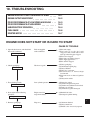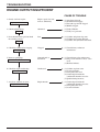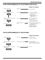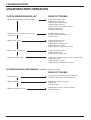
1
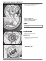
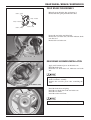
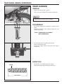
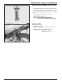
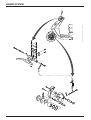
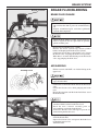
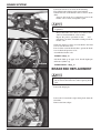
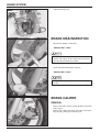
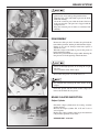
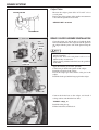
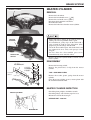
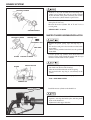
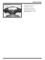
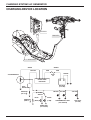
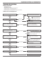
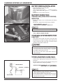
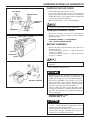
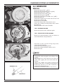
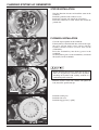
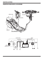
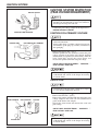
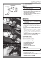
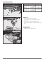
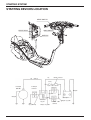
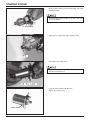
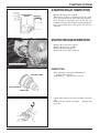
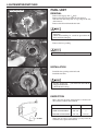
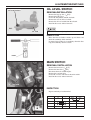
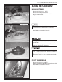
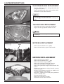
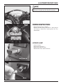
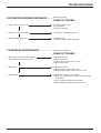
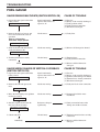
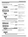
REAR WHEEL / BRAKE / SUSPENSION
TROUBLESHOOTING
Wobble or vibration in motorcycle
Tire pressure incorrect
Faulty tire
Bent rim
Loose wheel bearing
Swing arm bushing worn
Wheel out of balance
Soft suspension
Weak springs
Rear damper improperly adjusted, oil leakage
Hard suspension
Rear damper improperly adjusted
Bent shock absorber rod
Suspension noise
Loose fasteners
Worn shock
11-2
REAR WHEEL / BRAKE / SUSPENSION
REAR WHEEL
REMOVAL
Support the motor cycle on the main stand.
Loosen the rear brake adjuster, and remove the brake
cable.
Remove the brake arm joint B.
ADJUST
ADJUST NUT
NUT
ADJUST
NUT
Remove the muffler. ( 3-7 )
Remove the rear wheel mud guard.
Loosen the rear wheel U nut.
Remove the washer.
Remove the rear wheel.
U-NUT
U-NUT
U-NUT
INSPECTION
Turn the wheel, and check the rim for wobbles.
SERVICE LIMIT : Radical 2.0mm
Axial 2.0mm
INSTALLATION
Insert the rear wheel over the final shaft.
11-3
REAR WHEEL / BRAKE / SUSPENSION
Insert the washer, and tighten with the U nut.
TORQUE VALUE : 6.0~8.0kgf m
Install the brake arm joint B.
Install the rear brake cable.
Install the rear brake rod adjusting nut.
Install the rear wheel mud guard.
Install the muffler.
Check the free play of the brake after the rear wheel
assemblying
REAR BRAKE
Remove the rear wheel. ( 11-3 )
INSPECTION
Measure the brake drum of inner diameter
SERVICE LIMIT : 111mm
Measure the thickness of the brake lining.
SERVICE LIMIT : 2.0mm
11-4
REAR WHEEL / BRAKE / SUSPENSION
REAR BRAKE DISASSEMBLY
Manually open the brake shoe and remove it.
Remove the shoe spring from the brake shoe.
Loosen the rear brake arm fixing bolt.
Remove the rear brake arm, rear brake indicator, brake
cam, dust seal.
Remove the rear brake cam.
REAR
BRAKE
CAM
REAR
REAR BRAKE
BRAKE CAM
CAM
REAR
BRAKE
CAM
REAR BRAKE ASSEMBLY/INSTALLATION
Apply small amount of grease to the brake cam.
Install the brake cam.
Install the rear brake dust seal, indicator, rear brake
arm.
Align the punch marks of the brake arm and the
brake cam before assembly.
Remove the excessive grease after assembling the
shoe.
REAR
BRAKE
CAM
REAR
REAR BRAKE
BRAKE CAM
CAM
Install the brake shoe and spring.
Install the rear brake shoe to the rear brake cam.
Install the rear wheel.
Install the washer and U nut.
Check the brake for smooth operation.
11-5
REAR WHEEL / BRAKE / SUSPENSION
REAR CUSHION
REAR
REAR
CUSHION
REAR CUSHION
CUSHION
REMOVAL
Remove the luggage box. ( 3-3 )
Loosen the top and bottom rear cushion setting bolts.
Support the frame firmly prior to working.
SETTING
SETTING
BOLTS
SETTING BOLTS
BOLTS
DISASSEMBLY
Install the compressor attachment as shown in the
figure.
Install the cushion on the cushion compressor, and
compress the spring.
TOOLS : COMPRESSOR ATTACHMENT
REAR COMPRESSOR
Fix the bottom metal, and loosen the lock nut.
Remove the bottom metal.
Remove the stopper rubber, spring from the damper
component.
INSPECTION
Measure the rear cushion spring free length.
Check the damper rod for deflection or damage.
SPRING
FREE LENGTH
11-6
REAR WHEEL / BRAKE / SUSPENSION
REAR CUSHION ASSEMBLY/INSTALLATION
Assemble the spring, spring guide, and stopper rubber.
Apply thread locking agent to the lock nut, and install
the rear cushion compressor attachment on the damper
rod.
Fix the upper joint, and tighten the lock nut.
TORQUE VALUE : 4.0kgf m
TOOLS : REAR CUSHION COMPRESSOR
REAR CUSHION COMPRESSOR ATTACHMENT
INSTALLATION
REAR
REAR
CUSHION
REAR CUSHION
CUSHION
Install the rear cushion.
Tighten the top and bottom of the cushion with bolt.
TORQUE VALUE : UPPER SIDE 3.5kgf m
LOWER SIDE 3.5kgf m
SETTING
SETTING
BOLTS
SETTING BOLTS
BOLTS
11-7
BRAKE SYSTEM
12-0
12. BRAKE SYSTEM
SERVICE INFORMATION
TROUBLESHOOTING
BRAKE FLUID/BLEEDING
BRAKE PAD REPLACEMENT
12-1
12-1
12-3
12-4
BRAKE DISK INSPECTION
BRAKE CALIPER
MASTER CYLINDER
12-6
12-7
12-9
SERVICE INFORMATION
GENERAL SAFETY
Do not allow foreign material to enter the system when replenishing brake fluid.
To prevent chemical changes, do not mix different types of brake fluid.
Do not use the old brake fluid again.
Brake fluid can cause damage to painted, plastic, and rubber surfaces. Take precaution not to allow parts to be
contaminated by the brake fluid.
Do not reuse sealing washers.
Clean the disassembled parts with brake fluid, and check for any clogged passage with compressed air.
Bleed the brake hose after removing it.
TROUBLESHOOTING
HYDRAULIC DISK BRAKE
Braking power unsatisfactory
Air in the brake system.
Moisture in brake fluid
Brake pad and disk contaminated.
Caliper piston seal worn
Master cylinder piston seal worn
Brake pad worn
Caliper inside contaminated
Unsatisfactory caliper sliding part operation
Lopsided wear of brake pad and disk
Low brake fluid level
Clogged brake fluid line
Disk bent or distorted
Caliper piston seized or worn
Master cylinder piston seized or worn
Disk worn
Master cylinder inside contaminated
Brake lever bent
Hard brake lever movement or unsatisfactory
return
Brake system clogged
Caliper piston seized or worn
Unsatisfactory caliper sliding part operation
Brake fluid line clogged
Caliper piston seal worn
Master cylinder piston seized or worn
Brake lever bent
Brake drag
Brake pad and disk contaminated
Improper wheel alignment
Lopsided wear of brake pad and disk
Disk bent or distorted
Unsatisfactory caliper sliding part operation
Hydraulic system contaminated with dust.
12-1
BRAKE SYSTEM
MECHANICAL DRUM BRAKE
Poor brake performance
Improperly adjusted brake
Worn brake linings
Worn brake drum
Worn brake cam
Improperly installed brake linings
Brake cable sticking/needs lubrication
Contaminated brake linings
Contaminated brake drum
Worn brake shoes at cam contact areas
Improper engagement between brake arm and camshaft serrations
Brake lever hard or slow to return
Worn/broken return spring
Improperly adjusted brake
Sticking brake drum due to contamination
Worn brake shoes at cam contact areas
Brake cable sticking/needs lubrication
Worn brake cam
Improperly installed brake linings
Brake squeaks
Worn brake linings
Worn brake drum
Contaminated brake linings
Contaminated brake drum
12-2
BRAKE SYSTEM
MASTER
CYLINDER
MASTER
MASTER CYLINDER
CYLINDER
BRAKE FLUID/BLEEDING
BRAKE FLUID CHANGE
A contaminate disk or pad reduces braking power.
Do not allow the disk or pad to be contaminated by
oil.
Replace contaminated pads, and remove pollutants
from the disk completely.
Check the brake fluid level often, and replenish new
fluid as required. Do not spill fluid on painted,
plastic or rubber parts.
Remove the front handle cover. ( 3-6 )
Remove the master cylinder cap, master cylinder
holder, and diaphragm from the master cylinder.
Connect the bleeder hose to the bleeder valve. Loosen
the bleeder valve, and pump the brake lever repeatedly.
When there is no more fluid flowing out of the bleeder
valve, stop pumping the brake lever.
FRONT
CALIPER
FRONT
FRONT CALIPER
CALIPER
FRONT
CALIPER
AIR BLEEDING
BLEEDER VALVE
Fill the reservoir with DOT 3 or 4 brake fluid up to the
upper level.
To prevent chemical changed, do not use different
types of brake fluid.
Connect the recommended brake bleeder to the bleeder
valve.
Loosen the bleeder valve while pumping the brake
lever.
Repeat this operation until the brake fluid flows out of
the brake bleeder.
Check fluid level often, and replenish fluid if the
amount of fluid is reduced to the lower level.
Read the user’s manual carefully prior to
disassembling or using the brake bleeder.
Protect the bleeder valve with tape to prevent air
from entering the bleeder valve.
Repeat the above operation until there is no air flowing
out of the bleeder hose.
Squeeze the bleeder valve and operate the brake lever
to check the ingress of air.
Add brake fluid.
12-3
BRAKE SYSTEM
If the brake bleeder is not used, do the following,
First, fill the brake fluid up to the upper limit line.
Connect the hose to the bleeder valve to receive brake
fluid.
Squeeze the brake lever completely loosen the
bleeder valve 1/2 turn, and tighten it again.
Do not release the brake lever unitl the bleeder valve
is tightened.
Release the brake lever slowly to its fullest extent,
and leave it unattended for a few seconds.
Repeat the process specified in item
and
until there is no more air bubbles coming out of the
bleeder valve.
Check the fluid level often, and add fluid if the fluid
level is near the lower level.
If no air leaks out of the bleeder hose, operate the brake
lever to check the presence of air.
Assemble the bleeder valve.
TORQUE : 0.6kgf m
Add brake fluid up to upper level. Install diaphragm
and mater cylinder cap.
BLEEDER
BLEEDER
VALVE
BLEEDER VALVE
VALVE
TORQUE VALUE : 1.0kgf m
BRAKE PAD REPLACEMENT
When replacing brake pads, replace whole set.
Do not remove the brake hose when replacing brake
pads.
Loosen the hanger pin.
Loosen the 2 front brake caliper fixing bolts from the
front fork.
Remove the front caliper.
FIXING
BOLTS
FIXING
FIXING BOLTS
BOLTS
FIXING
12-4
BRAKE SYSTEM
To install a new brake pad into the brake, press the
piston to return to the original position.
Remove the hanger pin, pad shim, and brake pad.
HANGER
HANGER
PIN
HANGER PIN
PIN
BRAKE
BRAKE
PAD
BRAKE PAD
PAD
Verify that the pad spring is installed in specific
position.
PAD
SPRING
PAD
PAD SPRING
SPRING
PAD
Install a new brake pad, pad shim, and hanger pin.
HANGER
HANGER
PIN
HANGER PIN
PIN
Install the brake caliper into the left front fork.
Be careful not to damage the brake pad.
Tighten the caliper braket bolt.
TORQUE : 2.7kgf m
12-5
BRAKE SYSTEM
Tighten the hanger pin.
HANGER PIN
PIN
HANGER
HANGER
PIN
BRAKE DISK INSPECTION
Measure the thickness of the disk.
SERVICE LIMIT : 3.0mm
Measure the brake disk thickness at the several
points and replace if the smallest measurement is
less then the specified service limit.
Check the brake disk for bent and twist.
SERVICE LIMIT : 0.4mm
Replace the brake disk if the disk for damage or
cracks.
BRAKE CALIPER
REMOVAL
Remove the brake oil bolts and the brake hose from the
brake caliper.
Remove the caliper from the L. front fork and remove
the pad spring, hanger pin and brake pad.
12-6
BRAKE SYSTEM
Pay attention not to let the brake fluid adhere to the
parts because it can damage the painted surface.
Wind the hose joint with cloth to prevent the brake
fluid from leaking.
Clean the removed parts with the brake fluid and
make sure that the each port isn’t clogged with the
compressed air.
Keep the removed parts in order to avoid dust from
adhering.
DISASSEMBLY
CALIPER
CALIPER
CALIPER
CALIPER
Remove the slide pin, the L. bracket, the pin bush, the
boot and the pin boot, and the pin bolt from the caliper.
If there is any wear or damage in the boot, replace it
with the new one.
Wind the caliper with cloth to prevent the piston or
brake fluid from leaking.
Remove the piston from the caliper while blowing the
low-pressure air in the opening of the brake hose.
AIR
AIR
GUN
AIR GUN
GUN
Never use the high-pressure air or bring the air gun
too close.
Never touch the inside of the caliper
DUST
DUST
SEAL
DUST SEAL
SEAL
Disassemble the piston seal and the dust seal
PISTON
PISTON
SEAL
PISTON SEAL
SEAL
Pay attention not to damage the inner surface of the
caliper.
Clean the piston and the inside of the caliper and
remove the oil from the seal groove.
BRAKE CALIPER INSPECTION
Caliper Cylinder
Check the caliper cylinder bore for scoring, scratches
or other damage.
Measure the caliper cylinder I.D. in X and Y axis at
serveral points.
Replace the caliper cylinder if the largest measurement
is beyond the specified service limit.
CYLINDER
CYLINDER
CYLINDER
GAUGE
GAUGE
GAUGE
GAUGE
SERVICE LIMIT : 27.10 mm
CALIPER
CALIPER
CALIPER
12-7
BRAKE SYSTEM
Caliper Piston
CALIPER PISTON
Measure the caliper piston O.D. in X and Y axis at
several points.
Replace the caliper piston of the smallest measurement
is less than the specified service limit.
SERVICE LIMIT : 26.84 mm
MICROMETER
BRAKE CALIPER ASSEMBLY/INSTALLATION
LH.
BRACKET
LH.
LH. BRACKET
BRACKET
LH.
BRACKET
PAD
PAD
PAD
SPRING
SPRING
SPRING
PSTON
PSTON
PSTON
SEAL
SEAL
SEAL
PIN
PIN BUSH
BUSH
PIN
BUSH
PSTON
PSTON
PSTON
PSTON
DUST
SEAL
DUST
DUST SEAL
SEAL
DUST
SLIDE
SLIDE
PIN
SLIDE PIN
PIN
Clean the piston seal and the dust seal with the brake
fluid and install them in the caliper. Install the piston in
the caliper with the groove side of the piston facing the
pad.
Make sure that each part is free from dust or dirt
before reassembly.
Replace the dust seals and piston seals as a set
whenever they are removed.
When cleaning with the brake fluid, use the specified
brake fluid.
Apply the silicone grease to the pin bush.
Connect the pin bush to the portion of the caliper.
Install the pad spring in the caliper.
Install the caliper pin bolt and the slide pin in the
caliper.
Install the brake pad and the hanger pin in the caliper.
BRAKE
BRAKE
PAD
BRAKE PAD
PAD
Connect the brake hose to the caliper, and install 2
sealing washers and the brake hose bolt.
TORQUE : 3.5kgf m
Install the slide pin cap.
Fill the brake fluid, and bleed air.
12-8
BRAKE SYSTEM
MASTER CYLINDER
MASTER
CYLINDER
MASTER
MASTER CYLINDER
CYLINDER
REMOVAL
Remove the back mirror.
Remove the front handle cover. ( 3-6 )
Remove the rear handle cover. ( 3-6 )
Disconnect the front brake switch wire.
Drain the brake fluid.
Remove the brake hose from the master cylinder.
Brake fluid causes damage to the painted, plastic or
rubber parts. Do not spill fluid on these parts.
If contaminated, gently wipe off the fluid with a
piece of cloth or wash in water. Close hose joints
properly to prevent leakage of brake fluid.
Clean the disassembled parts with brake fluid, and
use compressed air to verify each passage is not
clogged.
Do not allow the disassembled parts to be
contaminated by waste material or dust.
MASTER
CYLINDER
FRONT STOP
SWITCH
Remove the master cylinder holder, and lift out the
master cylinder.
DISASSEMBLY
Remove the front stop switch.
Remove the piston boot, cir clip from the master
cylinder.
TOOL : SNAP RING PLIERS
Remove the washer, piston, spring from the master
cylinder.
Clean the master cylinder, reserve, master piston with
the recommended brake fluid.
MASTER CYLINDER INSPECTION
Check the piston periphery for kink or scratch.
Check the primary and secondary cups for wear.
Measure the O.D of the master pin
MASTER CYLINDER
SERVICE LIMIT : 10.90 mm
MICROMETER
12-9
BRAKE SYSTEM
MASTER CYLINDER
If there is any leak of fluid when installing new
piston, it may indicate the side wear of the cylinder
by the direction of the piston contacting face. In this
case, the master cylinder must be replaced also.
Check the master cylinder for scores, scratches or nicks
and replace if necessary.
Measure the master cylinder I.D. in X and Y axis at
several points.
SERVICE LIMIT : 11.08 mm
CYLINDER GAUGE
MASTER CYLINDER ASSEMBLY/INSTALLATION
MASTER CYLINDER
PRIMARY CUP
SECONDARY CUP
SNAP RING
SPRING
SPRING
MASTER CYLINDER
MASTER PISTON
Replace the piston, spring, cups and snap ring as a
set.
Be sure that each part is free from dust or dirt before
reassembly.
When cleaning with the brake fluid, use the specified
brake fluid.
Coat the piston cup with the fresh brake fluid and
install it on the piston. Install the spring with its larger
diameter end toward the master cylinder.
When installing the cups, do not allow the lips to
turn inside out. (Refer to the drawing.)
Note the installation direction of the snap ring.
Be certain that the snap ring is seated firmly in the
groove.
Install the rubber boot in the groove properly.
TOOL : SNAP RING PLIERS
PRIMARY CUP
MASTER
CYLINDER
MASTER
MASTER CYLINDER
CYLINDER
MASTER
CYLINDER
Install the master cylinder to the handle bar.
Install the holder with its “UP” mark facing
upwards, and align the holder joint with the punch
mark on the handle bar.
Tighten the holder upper bolt first.
12-10
BRAKE SYSTEM
MASTER
CYLINDER
MASTER
MASTER CYLINDER
CYLINDER
Install the brake hose to the master cylinder with 2 new
sealing washers and the hose bolt.
TORQUE VALUE : 3.5kgf m
Connect the brake stop swtich wire.
Fill the brake fluid, and bleed air.
Install the rear handle cover. ( 3-6 )
Install the front handle cover. ( 3-6 )
Install the back mirror.
12-11
MEMO
13. BATTERY/CHARGING SYSTEM
SERVICE INFORMATION
CHARGING DEVICES LOCATION
TROUBLESHOOTING
BATTERY REMOVAL/INSTALLATION
BATTERY INSPECTION
13-1
13-2
13-3
13-4
13-4
CHARGING SYSTEM INSPECTION
HEADLIGHT VOLTAGE INSPECTION
REGULATOR/RECTIFIER INSPECTION
A.C. GENERATOR
RESISTER INSPECTION
13-4
13-6
13-6
13-7
13-9
SERVICE INFORMATION
Do not place flammable materials near battery when charging. This can be a fire hazard as hydrogen gas is created
during charging battery.
Do not allow battery acid to come into contact with clothes, skin or eyes. Battery acid contact can cause burns or loss of
eye sight. If contact occurs, thoroughly clean with water, and if acid enters eyes, flush with water and see a doctor.
If battery acid gets on clothing, as it can seep through or make a hole through the clothing and make its way to the skin,
make sure to change clothing that has come into contact with battery acid and wash the battery acid from the clothes.
This vehicle has a maintenance-free(MF) battery. Because MF batteries use different charging equipment, take special
care when performing maintenance and especially when replacing parts. Not all regular battery equipment is
compatible with MF batteries.
When charging the battery, remove the battery from the frame and do not open stopper.
There is the possibility of damaging the regulator/rectifier, etc. if the terminal or coupler is separated/connected when
electricity is over flowing through the electrical devices. Make sure to turn the main switch OFF when performing
maintenance to the charging equipment.
If the battery is allowed to repeatedly lose all its charge, is repeatedly over-charged, or if it is left in an un-charged state,
the battery can be damaged, its life can be reduced, or it can lose some of its strength. It is important to note here that the
battery will naturally last 2-3 years of noromal use, and although it will re-charge, its load is reduced, leading to a loss in
battery strength.
It is possible for the battery to become overcharged from battery body load. If a battery cell becomes short-circuited and
if a state develops where voltage is not created between the terminals, the regulator will not operate and excessive
voltage will develops where voltage is not created between the terminals, the regulator will not operate and excessive
voltage will develop in the battery and normal cell electrolytes will decrease.
If the vehicle is not used for a long period, make sure to chage the battery every three months. If not so, the battery
ability to store electricity is reduced.
A new MF battery will not necessarily be ready for use in the vehicle with only the adding of battery acid. Make sure to
charge battery after the adding of battery water in the following instances :
-When open voltage (voltage between terminals) does not reach 12.4V after the adding of battery water : charge until
open voltage reaches at least 12. 8V.
-When battery acid temperature is under 0 : charge normally for 2-3 hours.
See the part location drawing for the location of charging system parts. ( 13-2 )
Follow the trouble shooting for charging equipment inspection. ( 13-3 )
The charging equipment may ofter appear to be malfunctioning if the couplers or connectors are incorrectly attached.
Make sure to check these connections before starting maintenance work on the charging equipment.
13-1
CHARGING SYSTEM / AC GENERATOR
CHARGING DEVICE LOCATION
BATTERY
RESISTER
A.C. GENERATOR
GREEN
WHITE
YELLOW
RED
RED
GREEN
A.C GENERATOR
FUSE
7A
REGULATOR/
RECTIFIER
BATTERY
(12V 3AH)
AUTOBYSTARTER
RESISTER
(5W 6.7 )
RESISTER
(30W 5.9 )
YELLOW YELLOW
DIMMER
SWITCH
BLUE
WHITE
(HIGH)
(LOW)
HEADLIGHT
(12V 35/35W)
13-2
SPEEDOMETER LIGHT
(12V 3Wx2EA)
YELLOW
TAIL LIGHT
(12V 5W)
CHARGING SYSTEM / AC GENERATOR
TROUBLESHOOTING
Battery is Overcharged
Headlight bulb is out.
No headlignt beam wire.
Headlight register is damaged (disconnected).
Lighting switch is connected incorrectly.
Regulator/rectifier is not grounded or connected incorrectly.
Problems with the Charging System
Measure battery voltage leakage.
ABNORMAL
Inspect the body of the register/rectifier.
NORMAL
Check charge level.
UNDER 14V
Check the voltage of the regulator/rectifier
battery lines and the ground line.
NORMAL
OVER 15V
OVER 14~15V
ABNORMAL
Short-circuited harness.
Damaged main switch.
Regulator/rectifier is damaged.
Battery is damaged.
ABNORMAL
Wire harness is short-circuited.
Coupeler is connected incorrectly.
ABNORMAL
Check the AC generator charging coil
NORMAL
Check the changing coil with the regulator/
rectifier coupler charging coil.
NORMAL
AC generator coupler connected incorrectly.
NORMAL
ABNORMAL
Damaged charging coil.
Check the lighting coil at the regulator/
rectifier coupler lighting coil line.
ABNORMAL
Inspact the AC generator charging/
lighting coil
NORMAL
NORMAL
ABNORMAL
AC generator coupler connected incorrectly.
Damaged charging/lighting coil.
Check the headlight lighting control voltage.
ABNORMAL
Damaged regulator/ rectifier
(darkened headlight)
ABNORMAL
Damaged headlight register.
ABNORMAL
Damaged regulator/ rectifier.
NORMAL
Inspect the headlight register.
NORMAL
Inspect the body of the register/rectifier.
NORMAL
Damaged Battery
13-3
CHARGING SYSTEM / AC GENERATOR
BATTERY REMOVAL/INSTALLATION
SETTING
SETTING
BOLT
SETTING BOLT
BOLT
Loosen the battery cover setting bolt.
Remove the battery cover.
After removing the negative “ ” terminal of battery
firstly, must remove the positive “ ” terminal of
battery.
Install in the reverse order of removal.
BATTERY INSPECTION
CHARGE LEVEL (OPEN-CIRCUIT VOLTAGE)
INSPECTION
Remove the battery cover and disconnect the battery
terminals.
Measure the voltage between the battery terminals.
- FULLY CHARGED : 13.0-13.2V
- INSUFFICIENTLY CHARGED : Under 12.3V
Use a digital voltmeter when measuring charge level.
Measure 30minutes later.
TOOL : DIGITAL CIRCUIT TESTER
CHARGING SYSTEM INSPECTION
LEAK TEST
Trun off the main switch, and remove the earth cable
from the battery. Connect an ampere meter between the
battery terminal and the earth cable, and check current
when the main switch is turned off.
Use an ampere meter while sequentially changing its
measuring range from large to small. If the current
level greater than the measuring limit is measured,
the ampere meter fuse may be cut.
Do not turn on the main switch while current is
being measured.
LEAK CURRENT : Not to exceed 1mA
BATTERY ADJUSTMENT VOLTAGE CHECK
Connect the voltmeter between the battery terminals.
Connect the amperemeter between the main fuse
termanals.
Start the engine and measure the charging voltage and
ampere while incresae the rpm gradually.
AMPERE METER
BATTERY
EARTH CABLE
13-4
CONTROL VOLTAGE (CHARGING SIDE) : 14.5 0.5V/5,000rpm
(LAMP SIDE) : 13.1~ 0.5V/5,000rpm
TERMINAL
Check with fully charge the battery which has the
voltage between terminal of 12.8~13.0V.
In case that the engine is started by the starter motor,
measurement must be performed after accelating
(charging) for 10 seconds.
CHARGING SYSTEM / AC GENERATOR
CHARGING VOLTAGE CHECK
VOLT METER
AMPERE METER
MAIN FUSE
TERMINAL
Use the full change battery (12.8~13.2V)
In case that charging the voltage is not controled
properly, the battery cannot be used due to the battery
solution dried up by over charging and the deformation
caused by the damage of the plates.
Battery control voltage : 14.5 0.5V(5,000rpm)
If you have 1EA of tester, measure current first.
MAIN FUSE
FILLER CAP
CHARGING CURRENT CHECK
SAFETY VENT
FILTER
Check the charging current passed through the
generator assy, regulator comp is normal with the
discharged battery.
CHARGING CURRENT : 1.5~2.4A/5,000rpm
TOOL : DIGITAL CIRCUIT TESTER
BATTERY CHARGING
Remove the battery from the frame, and connect it to
the battery charger.
-Connect the charger positive (+) cable to the battery
positive (+) terminal.
-Connect the charger negative (-) cable to the battery
negative (-) terminal.
PLATE
SEPARATOR
PLATE
Do not connect the charger to the battery coupler
terminals.
Never open the sealed filler cap.
BATTERY CHARGER
The battery generates hydrogen gas which can be
highly explosive. Do not smoke or allow flames or
sparks near the battery, easpecially while charging it.
Turn power ON/OFF at the charger, not at the
battery terminals. If the cable is disconnected or
connected at the battery terminal during charging,
spark may jump and ignite the flammable gas.
Always remove the battery from the frame when
charging it. If the battery is charged while installed in
the frame, the electrolyte may spill and corrode the
frame components.
CHARGING CURRENT : 0.3A
CHARGING TIME : 8~10h
Do not let the electrolyte temperature rise above 45
(113 ). If the electrolyte temperature becomes
too high, lower the charging current.
Quick-charging will shorten the battery life and
cause battery damage. It chould only be done in
emergency; slow-charging is prefered.
13-5
CHARGING SYSTEM / AC GENERATOR
HEADLIGHT VOLTAGE INSPECTION
Remove the front cover. ( 3-5)
Check voltage with the headlight coupler connected.
After starting the engine, place the dimmer switch to
HI and check the voltage between the blue (+) and
green (-) wires of the headlight coupler.
Measurement is performed in AC area.
CONTROL VOLTAGE : 12.6~13.6V/5,000rpm
If voltage is incorrect, check the regulator/rectifier.
REGULATOR/RECTIFIER INSPECTION
HARNESS CIRCUIT INSPECTION
Remove the front cover. ( 3-5 )
Remove the 4P coupler of the regulator/rectifier and
inspect the wiring circuit in the main harness side
terminal.
ITEM
MEASUREMENT LOCATION
BATTERY WIRE Voltage between red “ ” and green “ ”.
LEVEL
AREAS OF INSPECTION IF INCORRECT
There must be battery voltage. Damaged, disconnected main fuse/harness.
CHARGING
Resistance between white wire and
COIL
earth wires. Disconnect the starter.
AC generator (charging, lighting coil
Resistance between yellow wire and
coupler connection damage) resister(6.7
LIGHTING
COIL
Inspect
earth wires. Disconnect dimmer
0.4~1.0 (20 )
5W) headlight lighting circuit.
0.2~0.8 (20 )
switch connection
part after at least 10 minutes later.
REGULATOR/RECTIFIER INSPECTION
(BATEERY TERMINAL)
(LAMP TERMINAL)
TERMINAL ARRANGEMENT
If the inspection of the harness side proves to be
satisfactory, check the regulator/rectifier coupler for
faulty connection, and measure the resistance between
the terminals of the regulator/rectifier.
RESISTANCE VALUE
Tester
Tester
A
L
A
(EARTH TERMINAL)
13-6
5-100
B
E
E
3-50
L
(CHARGING TERMINAL)
B
5-100
CHARGING SYSTEM / AC GENERATOR
A.C. GENERATOR
COOLING FAN
FAN
COOLING
COOLING
FAN
REMOVAL
NUT
NUT
NUT
Remove the luggage box. ( 3-3 )
Remove the plug maintenance cover. ( 3-3 )
Remove the center cover. ( 3-3 )
Remove the floor side cover. ( 3-4 )
Remove the floor panel. ( 3-4 )
Remove the engine hanger side RH. cover. ( 3-5 )
Remove the plug cap.
Loosen the 3 washer screws, remove the fan cover and
the fan cover element A,B.
Remove the fan cover rubber.
Loosen the 2 flange bolts, remove the fan cover.
Loosen the 4 cooling fan fixing flange bolts, remove
the cooling fan.
Hold the flywheel with a universal holder.
TOOL : UNIVERSAL HOLDER
Remove the flywheel with a ACG rotor puller.
TOOL : ACG ROTOR PULLER 0750-00004
Remove the connector/coupler on the wire harness or
starter motor. Remove the ground wires.
FLYWHEEL
FLYWHEEL
FLYWHEEL
FLYWHEEL
Loosen the 2 pulse generator fixing flange bolts,
remove the pulse generator.
Loosen the 2 stator fixing flange bolts.
Remove the grommet from the crankcase cover.
Remove the stator.
Insert the puller shaft and remove the flywheel after
inserting the ACG rotor puller and securing it with
spanner.
The flywheel may easily removed if you rotate the
puller while tapping the roller shaft with metal
hammer.
Always use a holder and a puller to remove the
flywheel. Do not try to remove the flywheel by
hammering directly on it. The crankshaft or
components could be damaged.
Remove the woodruff key with care not to lose it.
ACG
ACG
ROTOR
PULLER
ACG ROTOR
ROTOR PULLER
PULLER
WOODRUFF KEY
CRANKSHAFT
13-7
CHARGING SYSTEM / AC GENERATOR
STATOR INSTALLATION
Note the direction of stator, and install the stator on the
crankcase.
Install the grommet to R. crankcase cover.
Install AC generator wire coupler to wire harness.
Install the connector to starter motor, then install the
ground wire.
STATOR COMP
COMP
STATOR
STATOR
COMP
FLYWHEEL INSTALLATION
Clean the tapered portion of the crankshaft.
If the flywheel is installed with dust or dirt on the taper,
the taper will not make secure contact with the
flywheel and there will be excessive force on the
woodruff key.
Insert the woodruff key into the key groove in the
crankshaft.
Set the flywheel groove to the woodruff key and install
the flywheel on the crankshaft.
WOODRUFF
WOODRUFF
KEY
WOODRUFF KEY
KEY
Before installing the flywheel, check that no nuts or
bolts are magnetically attached to the flywheel.
Installing the flywheel with anything attached to it
could damage the stator coil.
Hold the flywheel rotor with a holder and tighten the
bolt (nut) to the specified torque.
FLYWHEEL
FLYWHEEL
FLYWHEEL
FLYWHEEL
Install the cooling fan.
Install the fan cover.
Install the luggage box. ( 3-3 )
COOLING
FAN
COOLING FAN
FAN
COOLING
13-8
CHARGING SYSTEM / AC GENERATOR
A.C. GENERATOR(CHARGING COIL)
INSPECTION
This test is done with the starter mounted to the
engine.
Remove the center cover.
Disconnect the AC generator coupler. ( 3-3 )
Measure the resistance of the charging coil (between
the white wire and ground) and the lighting coil
(between the yellow wire and ground).
STANDARD RESISTANCE (20 )
BETWEEN WHITE WIRE AND GROUND : 0.4~1.0
BETWEEN YELLOW WIRE AND GROUND : 0.2~0.8
RESISTER INSPECTION
Remove the front cover. ( 3-5 )
Measure the resistance between the register lead wire
and ground.
STANDARD VALUE (20 )
RESISTER (6.7 5W) GREEN/BLACK/BODY GROUND : 6.3~7.1
RESISTER (5.9 30W)PINK/BODY GROUND : 5.6~6.5
Problems with the resister are caused by operational
problems of the starter.
13-9
MEMO
14. IGNITION SYSTEM
SERVICE INFORMATION
IGNITION DEVICES LOCATION
TROUBLESHOOTING
IGNITION SYSTEM INSPECTION
(PEAK VOLTAGE MEASUREMENT)
IGNITION COIL
14-1
14-2
14-3
14-4
14-5
EXCITE COIL INSPECTION
PULSE GENERATOR INSPECTION
IGNITION TIMING INSPECTION
CDI UNIT
SIDE STAND IGNITION
CUT-OFF SWITCH
14-6
14-6
14-7
14-7
14-8
SERVICE INFORMATION
GENERAL SAFETY
Refer to the malfunction diagnosis when inspecting ignition devices.
Because the ignition devices have installed electrical advancer devices, it is impossible to adjust ignition timing.
Be careful when handling the ignition devices as they can become easily damaged if dropped or bumped. Also, do not
disconnect or connect the connectors and couplers when the main swtich is turned ON as excessive electric current can
cause damage in the unit. Always perform maintenance work on the ignition devices with the main switch turned OFF.
Ignition devices can often appear to be malfuctioning when the couplers or connectors are disconnected. Check these
connections before working on.
Use recommended spark plug. Using incorrect spark plug may make the engine run badly or damage the engine.
This manual gives explanations on inspections to receive peak voltage. As inspections for coil resistance values are also
included, it may be difficult to make a correct determination.
Conduct inspection on the main swtich by referring to the wiring diagram continuity chart. ( chapter 16 )
14-1
IGNITION SYSTEM
IGNITION DEVICES LOCATION
SPARK PLUG
MAIN SWITCH
CDI UNIT
IG COIL
A.C. GENERATOR
BLUE/YELLOW
GREEN
BLACK/YELLOW
BLACK/RED
BLACK/WHITE
A.C
GENERATOR
IGNITION
COIL
PULSE
GENERATOR
14-2
CDI UNIT
SIDE
STAND
SWITCH
MAIN SWITCH
SPARK
PLUG
IGNITION SYSTEM
TROUBLESHOOTING
Spark plug does not emit sparks.
ABNORMAL STATE
POSSIBLE CAUSES (START FROM 1 AND GO THROUGH LIST IN ORDER)
IGNITION COIL PRIMARY VOLTAGE
EXCITE COIL
PULSE GENERATOR
Maximum voltage is low.
1. Using a tester with a low internal resistance.
2. Cranking speed is low.
Battery is low or kick power is weak.
3. Influence of tester sampling time (normal state if measured a
number of times and shows over the set voltage).
4. Problem in ignition system wiring (disconnected, damaged).
5. Ignition coil is damaged.
6. Excite coil is damaged (measure peak voltage).
7. CDI unit is damaged (when no porblems in 1~6 and spark plug
does not emit sparks)
No, or almost no peak voltage.
1. Adaptor is connected incorrectly.
2.Main switch damaged.
3. CDI unit coupler is connected incorrectly.
4. CDI unit ground wire disconnection.
5. Damage to excite coil (measure peak voltage).
6. Pulse generator is damaged (measure peak voltage).
7. Peak voltage adaptor is damaged.
8. CDI unit is damaged (when no problems in 1~7 and no sparks
emitted from spark plug).
Spark plug peak voltage is normal but
spark plug does not emit sparks.
1. Damage to spark plug or leakage of ignition coil secondary current.
2. Damaged ignition coil.
Peak voltage is low.
1. Using a tester with a low internal resistance.
2. Cranking speed is too low.
Battery is insufficiently charged or kick power is weak.
3. Influence of tester sampling time (normal state if measured a
number of times and shows over the set voltage)
4. Excite coil is damaged (when 1~3 is okay).
No, or almost no peak voltage.
1. Peak voltage adaptor is damaged.
2. Excite coil is damaged.
Maximum voltage is low.
1. Using a tester with a low internal resistance.
2. Cranking speed is too low.
Battery is insufficiently charged or kick power is weak.
3. Influence of tester sampling time (normal state if measured a
number of times and shows over the set voltage).
4. Pulse generator is damaged (when 1~3 is okay).
No, or almost no maximum voltage.
1. Maximum voltage adaptor is damaged.
2. Pulse generator is damaged.
14-3
IGNITION SYSTEM
DIGITAL TESTER
IGNITION SYSTEM INSPECTION
(PEAK VOLTAGE MEASUREMENT)
When sparks are not emitted from spark plug, after
checking for disconnection in wires and looseness,
measure peak voltage for each wire.
Connect the peak voltage adaptor to the digital tester.
DAELIM PVA MULTI TESTER
PEAK VOLTAGE ADAPTOR
IGNITION COIL
IGNITION COIL PRIMARY VOLTAGE
UNIT SIDE INITIAL TERMINAL
Make sure each wire is correctly connected to ensure
correct measurement.
Inspect when there is cylinder compression pressure
and with the spark plug cap securely connected to
the spark plug.
Remove the luggage box. ( 3-3 )
With the ignition coil wire connected, contact the peak
voltage adaptor to the initial wire adaptor terminal
(black/yellow) and ground (on vehicle body.). Turn the
main swtich ON, operate the starter motor, and
measure the ignition coil initial side peak voltage.
CONTACT POINTS : BLACK/YELLOW TERMINAL “ ”-BODY EARTH “ ”
PEAK VOLTAGE : OVER 120V
When measuring voltage, do not touch the metal part
of the handle rod as there is the danger of receiving
an electric shock.
EXCITE COIL
Assemble the spark pug to the cylinder head, inspect
in a state having compression pressure.
WIRE HARNESS
UNIT COUPLER
CDI UNIT
Remove the luggage box. ( 3-3 )
Remove the CDI unit. ( 14-7 )
Remove the coupler from the CDI unit contact the peak
voltage adaptor to the excite coil wire (black/red and
green) of the harness side coupler.
Operate the starter motor and measure the excite coil
peak voltage.
CONTACT POINTS : BLACK/RED TERMINAL “ ”-BODY EARTH “ ”
PEAK VOLTAGE : OVER 120V
EXCITE COIL
14-4
When measuring voltage, do not touch the metal part
of the handle rod as there is the danger of recieving
an electric shock.
IGNITION SYSTEM
PULSE GENERATOR
WIRE HANESS
UNIT COUPLER
Inspect with the spark plug assembled and while
there is compression pressure.
Remove the CDI unit. ( 14-7 )
Remove the coupler from the CDI unit and connect the
peak voltage adaptor to the pulse generator wire (blue/
yellow and green) of harness coupler.
Operate the starter motor and measure the peak voltage
of the pulse generator coil.
EXCITE COIL
CONTACT POINTS : BLUE/YELLOW TERMINAL “ ”-BODY EARTH“ ”
PEAK VOLTAGE : OVER 1.5V
When measuring voltage, do not touch the metal part
of the handle rod as there is the danger of receiving
an electric shock.
IGNITION
IGNITION
COIL
IGNITION COIL
COIL
Perform the following inspections if measured peak
voltage in the CDI unit coupler portion is abnormal.
Disconnect the AC generator cord coupler and connect
the adaptor.
In the same manner as with the unit coupler side,
measure peak voltage and compare with the first peak
voltage.
When the measured value in the unit side is abnormal
and normal in the pulse generator side, the problem is
either incorrect coupler connection or disconnection of
the wire harness.
When both measurements are abnormal, this indicates
a problem with the pulse generator. Refer to the
malfunction diagnosis are go through each step.
IGNITION COIL
REMOVAL/INSTALLATION
FIXING
FIXING
SCREW
FIXING SCREW
SCREW
Remove the luggage box. ( 3-3 )
Remove the plug maintenance cover.
Remove the spark plug cap.
Loosen the ignition coil fixing bolt.
Disconnect the ignition coil wire.
Remove the ignition coil.
Install in the reverse order of removal.
Arrange the cords in the right place.
INSPECTION (RESISTANCE MEASUREMENT)
Remove the luggage box. ( 3-3 )
Measure primary coil resistance between the green and
black/yellow terminals.
STANDARD VALUE : 0.1~0.5 (20 )
14-5
IGNITION SYSTEM
Measure the secondary coil resistance between the plug
cap and green wire terminals.
RESISTANCE VALUE
(SPARK PLUG CAP CONNECTION) : 6.5~9.5
(20 )
The coil which the resistance value indicate
“ ”(disconnection) remove the plugcap, and measure
the resistance of secondary coil.
Measure the resistance between the high tension code
and green code terminals.
RESISTANCE VALUE : 2.6 1.25
(20 ).
EXCITE COIL INSPECTION
Assembly the spark plug to the cylinder head, and
inspect in an state having compression pressure.
Remove the luggage box. ( 3-3 )
Remove the connection of the AC Generator wire
connector (black/red), measure the resistance between
the terminal of AC generator and body earth.
STANDARD VALUE : 500
20
(20 )
PULSE GENERATOR INSPECTION
The inspection of pulse generator is performed in a
state assembling to the engine.
Remove the luggage box. ( 3-3 )
Remove the connection of the AC generator 6P
coupler, and measure the resistance between the blue/
yellow of starter and green code.
STANDARD VALUE : 100
20
(20 )
IGNITION TIMING INSPECTION
As a CDI device is used in this vehicle, there is no
need for adjusting ignition timing. If ignition timing
problems occur, inspect the CDI unit and the AC
generator and replace if any malfunctions are found
in the devices.
Ignition timing inspection well read the instruction
manual of timing light or revolution-indicator, and
handle it exactly.
14-6
IGNITION SYSTEM
Warm up the engine.
Remove the center cover.
Remove the floor panel.
Remove the fan cover.
Connect timing light to the high-tension cord.
When engine rpms are at 1,800, ignition timing is
correct if the “F” mark and crank case index mark are
aligned.
INDEX
IGNITION TIMING : 17 DEGREES 2 BTDC/1,800 rpms
F MARK
Index mark must face the spark plug.
CDI UNIT
REMOVAL/INSTALLATION
Remove the luggage box. ( 3-3 )
Disconnect the coupler from the CDI unit and remove
CDI Unit.
Install in the reverse order of removal.
CIRCUIT INSPECTION
Remove the coupler from the CDI unit, and check the
ignition system circuits from the wiring coupler side.
CDI
UNIT
CDI
CDI UNIT
UNIT
CDI
UNIT
INSPECTION ITEM
CHECK POINT
PULSE GENERATOR BLUE/YELLOW AND GREEN
STANDARD VALUE
50~200 (20 )
IGNITION COIL
-PRIMARYCOIL
BLACK/YELLOW AND GREEN 0.1~0.5 (20 )
-SECONDARY COIL GREEN AND HIGH-TENSION CORD
(ATTACH THE PLUG CAP) 6.3~10.3K (20 )
(DETACH THE PLUG-CAP) 3.3
K (20 )
TESTING BY CDI TESTER
Check the CDI unit spark performance by using a CDI
tester.
Read tester manual carefully prior to using the tester.
SIDE STAND IGNITION
CUT-OFF SWITCH
INSPECTION
SIDE
STAND
SWITCH
SIDE
SIDE STAND
STAND SWITCH
SWITCH
SIDE
Remove the plug maintenance cover/ center cover.
( 3-3 )
Remove the coupler of the side stand switch.
Check for continuity between the terminal as shown
below:
14-7
IGNITION SYSTEM
ITEM
TERMINAL
SPECIFICATION
ON
(Side stand is
Retracted)
BLACK/WHITE
AND GREEN
NO
CONTINUITY
OFF
(Side stand is
Lowered)
BLACK/WHITE
AND GREEN
CONTINUITY
SIDE
STAND
SWITCH
SIDE
SIDE STAND
STAND SWITCH
SWITCH
SIDE
STAND
SWITCH
REMOVAL
Remove the floor side cover. ( 3-4 )
Remove the plug maintenance cover/ center cover.
( 3-3 )
Remove the side stand switch mounting 2 bolts.
Release the wire clamps and remove the side stand
switch.
INSTALLATION
SIDE STAND
STAND
SIDE
STAND
SIDE
SWITCH COUPLER
COUPLER
SWITCH
COUPLER
SWITCH
FAN
SCREW
FAN
FAN SCREW
SCREW
14-8
Install in the reverse order of removal.
15. STARTING SYSTEM
SERVICE INFORMATION
STARTING DEVICES LOCATION
TROUBLESHOOTING
15-1
15-2
15-3
STARTER MOTOR
STARTER RELAY INSPECTION
STARTER PINION GEAR INSPECTION
15-4
15-7
15-7
SERVICE INFORMATION
GENERAL SAFETY
When performing maintenance on the starter motor and related parts, turn the main switch to OFF. There is the
danger of the starter motor unexpectedly operating if the main switch is not turned to OFF.
First check connection with battery and battery charge level before beginning maintenance on the starter motor.
It is possible for the starter motor coil to become damaged if the starter is operated when the engine does not turn over.
15-1
STARTING SYSTEM
STARTING DEVICES LOCATION
START SWITCH
START RELAY
MAIN SWITCH
BATTERY
15-2
STARTING SYSTEM
TROUBLESHOOTING
Starter motor does not rotate (No response from starter motor).
Check to see if the fuse is burned out.
Check to turn on the lamp of stop switch.
With the main switch turned to ON, squeeze
the brake lever. In this state push the starter
button and check if a clicking noise then an
operating noise is emitted from the starter
relay.
Remove the starter motor “ ” wire, connect
it to the battery “ ” terminal and check to
see if the starter motor rotates (because a
large amount of current flows in this test, do
not use thin wire).
CLICKS
ROTATES
NO CLICK.
DOES NOT ROTATE
Incorrect starter
motor connecion
Remove the coupler from the starter replay
and inspect the relay coil ground wire.
Incorrect starter motor
Faulty starter switch.
NO CONTINUITY.
Incorrect connection with the switch
terminals or harness disconnection.
CONTINUITY.
Check the starter relay voltage in the starter
relay coupler with the coupler connected.
NO VOLTAGE.
Damaged main or starter switch.
Incorrect connection with coupler connector.
VOLTAGE MEASURED.
Disconnection in starter switch wire.
Faulty brake stop switch.
Check the operation of the starter relay.
ABNORMAL
NORMAL
Loose or poor contact at starter relay switch
connector.
Faulty starter relay switch.
Starter motor rotates but crank shaft does’t
Incorrect starting clutch.
Incorrect starter gear.
Starting clutch slip
Starter motor operates in free-wheel
Internal fault of starter motor
Driven gear slips.
Weak rotational power in starter motor
Battery is insufficiently charged.
Incorrect connection of battery terminal cord.
Damaged starter motor.
Ground wire is connected incorrectly
Brush is damaged or worn.
Starter motor and crank shaft rotate but does
not turn engine over.
Incorrect starting system.
Faulty engine.
15-3
STARTING SYSTEM
FIXING
FIXING
BOLT
FIXING BOLT
BOLT
STARTER MOTOR
REMOVAL/INSTALLATION
Remove the luggage box. ( 3-3 )
Remove the center cover. ( 3-3 )
Remove the floor side RH. cover. ( 3-4 )
Disconnect the starter wire connector, remove the wire
from the wire fixing clamp.
Loosen the 2 starter motor fixing bolts.
Remove the starter motor.
Install in the reverse order of removal.
Accurately tighten the earth wire.
Turn off the main switch prior to servicing the starter
motor. If power is connected, the starter motor may
be activated and damaged.
DISASSEMBLY
Remove the starter motor screws and remove the motor
cover.
Record the order so the parts can be installed
correctly later.
INSPECTION
Check for continuity of the starter motor case.
-Between cord terminal“ ” and bracket“ ”: normal
if no continuity.
-Between cord terminal and brush (black wire) :
normal if there is continuity.
If abnormal, replace with a new one.
Measure the brush length. Replace the brush if it is
worn beyond the service limit.
SERVICE LIMIT : 3mm
15-4
STARTING SYSTEM
Check the commutator for :
-Damage or abnormal wear.
Replace with a new
one.
-Discoloration of the commutator bar.
Replace
with a new one.
-Metallic debris between commutator bars.
Clean
it off.
Check for continuity between pairs of commutator
bars.
Make a continuity check between individual
commutator bars and the armature shaft.
There should be no continuity.
Check the bearings.
-Do not rotate smoothly.
Replace with a new one.
-Loose bearing.
Replace with a new one.
STARTER MOTOR ASSEMBLY
Carefully insert the armature shaft into the front
bracket.
Align the front bracket notch with the brush.
The sliding surcfaces of the brushes can be damaged
if they are not installed properly.
15-5
STARTING SYSTEM
Insert the brush spring into the brush holder and install
the front bracket.
Insert the brush spring with care so that it does not
lean in the holder.
Apply grease to both ends of the armature shaft.
Install the starter motor cover.
The coil may be damaged if the magnet pulls the
armature against the case.
Align the front bracket with the cover.
Tighten the washer screw.
15-6
STARTING SYSTEM
STARTER RELAY INSPECTION
STARTER RELAY
BATTERY
SWITCH
Remove the luggage box. ( 3-3 )
When battery voltage is applied between the starter
relay green/yellow wire and yellow/red terminals,
there should be continuity between the red and
red/white terminals. The terminals are distinguished by
the corresponding wire color of the wire harness
connector.
STARTER PINION GEAR INSPECTION
Remove the L. side cover. ( 7-2 )
Remove the drive face. ( 7-6 )
Remove the starter pinion gear.
Install in the reverse order of removal.
STARTER
STARTER
PINION
GEAR
STARTER PINION
PINION GEAR
GEAR
DRIVE
DRIVE
FACE
DRIVE FACE
FACE
INSPECTION
STARTER PINION
Wear or damage to the pinion, reduction gears.
Replace with a new one.
Worn journals.
Replace with a new one.
REDUCTION GEAR
PINION GEAR
Check if the pinion gear moves smoothly along the
axis.
Pinion gear does not move smoothly.
Replace with
a new one.
15-7
MEMO
16. LIGHTS/METER/SWITCHES
SERVICE INFORMATION
TROUBLESHOOTING
FUEL UNIT
OIL LEVEL SWITCH
MAIN SWITCH
16-1
16-1
16-2
16-3
16-3
HANDLE SWITCH INSPECTION
FRONT STOP SWITCH INSPECTION
BULBS REPLACEMENT
METER REPLACEMENT
HORN INSPECTION
16-4
16-4
16-5
16-6
16-7
SERVICE INFORMATION
GENERAL SAFETY
Refer to tester owner’s manuals when performing continuity inspections.
Refer to wiring diagram (chapter 17) for switch continuity.
After inspecting and/or performing maintenance work make sure the wires and cables are properly placed and
connected.
TROUBLESHOOTING
Fuel meter indicator malfunctioning
Coupler separated.
Harness disconnected.
Float operation malfuction.
Fuel unit damaged.
Meter damaged.
Fuel meter needle unstable
Coupler loose.
Fuel unit damaged.
Meter damaged.
Headlight hi-lo not operating
Oil indicator light not operating
(when there is oil).
Burned out fuse.
Battery insufficiently charged.
Main swtich damaged.
Meter damaged.
Oil level switch damaged.
Loose connector.
Harness disconnection.
Oil indicator does not turn off (when oil is out)
Oil level switch damaged.
Green/red wire joined.
Bulb malfunction.
Dimmer switch damaged.
16-1
LIGHTS/METER/SWITCHES
FUEL UNIT
FUEL
FUEL UNIT
UNIT SET
SET CAP
CAP
FUEL
UNIT
SET
CAP
REMOVAL
Remove the luggage box. ( 3-3 )
Remove the fuel unit wire from the wire harness.
Turn the fuel unit fixing unit set cap comp to the left,
and remove it.
Remove the fuel unit from the fuel tank.
Be careful of prevention the fuel unit wire from
damaging.
When disassembling, be careful of prevention the
float arm from damaging.
FUEL
FUEL
UNIT
FUEL UNIT
UNIT
BASE
PACKING
BASE
BASE PACKING
PACKING
BASE
PACKING
Remove the base packing.
Check for damage.
INSTALLATION
Install the base packing to the fuel tank.
Install the fuel unit.
Install it aligning the part of the fuel unit with the
loop part of fuel tank.
Check the fuel leakage.
INSPECTION
Move the float upward and downward, and measure
the resistance between the terminals.
WIRE TERMINAL
FLOAT
16-2
FLOAT UPPER LINE FLOAT LOWER LINE
GREEN AND YELLOW/WHITE
33
400~750
GREEN AND BLUE/WHITE
400~750
33
BLUE/WHITE AND BLUE/WHITE
450~750
450~750
When the measured value differs greatly from the
standard value, replace the fuel unit.
LIGHTS/METER/SWITCHES
OIL LEVEL SWITCH
OIL
OIL
LEVEL
SWITCH
OIL LEVEL
LEVEL SWITCH
SWITCH
REMOVAL/INSTALLATION
Remove the luggage box. ( 3-3 )
Remove the body cover.
Loosen the bolt jointed with the fuel tank.
Remove the wire of oil level switch.
Remove the oil level switch from the oil tank.
Install in the reverse order of removal.
OIL
OIL TANK
TANK
OIL
TANK
Disassemble after adjusting the oil level.
INSPECTION
Move the float to farthest extreme up and down and
check the continuity of the terminals.
It’s normal state if there is no continuity when the float
is up, but continuity when it is down.
FLOAT
MAIN SWITCH
REMOVAL/ INSTALLATION
Remove the front cover. ( 3-5 )
Remove the inner box. ( 3-5 )
Disconnect the main switch coupler.
Remove the seat lock cable.
Loosen the 2 screws and remove the main switch.
Install in the reverse order of removal.
MAIN SWITCH
SWITCH
MAIN
MAIN
SWITCH
INSPECTION
Inspect continuity of each terminal.
TERMINAL
ON
OFF
LOCK
COLOR BLACK/WHITE GREEN
RED
BLACK
16-3
LIGHTS/METER/SWITCHES
HANDLE SWITCH INSPECTION
Remove the front handle cover. ( 3-6 )
Remove the handle switch coupler, connector, and
inspect continuity of each terminal.
If abnormal, inspect the switch.
STARTER SWITCH
LIGHTING SWITCH
LIGHTING
SWITCH
LIGHTING
LIGHTING SWITCH
SWITCH
OFF
FREE
(N)
PUSH
PO
COLOR YELLOW/RED
GREEN
(N)
H
BROWN
COLOR / WHITE BROWN YELLOW PINK
STARTER
SWITCH
STARTER
STARTER SWITCH
SWITCH
DIMMER
DIMMER
SWITCH
DIMMER SWITCH
SWITCH
WINKER SWITCH
DIMMER SWITCH
LO
L
N
N
HI
R
COLOR BROWN WHITE BLUE
COLOR SKY BLUE ORANGE
GRAY
HORN SWITCH
FREE
WINKER
WINKER
WINKER
SWITCH
SWITCH
SWITCH
PUSH
COLOR LIGHT GREEN
BLACK
HORN
HORN
SWITCH
HORN SWITCH
SWITCH
FRONT STOP SWITCH INSPECTION
Remove the front handle cover. ( 3-6 )
Remove the black wire and green/yellow wire
terminals inside the speedometer assembly, and check
the following.
-When the brake lever is pulled - continuity.
-When the brake lever is released - no continuity.
STOP
SWITCH
FRONT STOP
STOP SWITCH
SWITCH
FRONT
FRONT
STOP
SWITCH
16-4
LIGHTS/METER/SWITCHES
BULBS REPLACEMENT
HEADLIGHT BULB
Remove the front cover. ( 3-5 )
Remove the headlight rubber cover.
Push down on the socket and turn to the left.
Replace with new bulb.
HEADLIGHT
HEADLIGHT
RUBBER
COVER
HEADLIGHT RUBBER
RUBBER COVER
COVER
HEADLIGHT
BULB
HEADLIGHT
HEADLIGHT BULB
BULB
HEADLIGHT
BULB
Before replacing the bulb, be sure to check the
swtiches for loose connection of the connectors.
Install in the reverse order of removal.
Headlight bulbs become very hot while the headlight
is ON, and remain hot for a while after they are
turned OFF.
Be sure to turn the ignition switch OFF and let the
bulb cool down before replacement.
If you touch the bulb with your bare hands, clean it
with a cloth moistened with denatured alcohol to
prevent early bulb failure.
Be sure to install the dust cover after replacing the
bulb.
FRONT WINKER BULB
Remove the front cover. ( 3-5 )
Remove the bulb from the socket, replace with new bulb.
Install in the reverse order of removal.
PAN
PAN
SCREW
PAN SCREW
SCREW
16-5
LIGHTS/METER/SWITCHES
REAR WINKER BULB REPLACEMENT
Press the winker lens groove and open the winker lens
using plain screwdriver.
Remove the bulb from the socket, replace with new bulb.
Install in the reverse order of removal.
Pay attention not to damage the lens.
Do not apply excessive force when removing the
lens.
PAN
SCREW
PAN
PAN SCREW
SCREW
PAN
TAILLIGHT BULB REPLACEMENT
Loosen the 2 pan screws, remove the tail light lens.
Replace the tail stop light bulb with the new one.
Pay attention not to damage the tail light lens when
removing it.
PAN
SCREW
PAN
PAN SCREW
SCREW
PAN
METER BULB REPLACEMENT
BULB
BULB
BULB
BULB
Remove the front handle cover. ( 3-6 )
Remove the bulb socket, replace with new bulb.
SPEEDOMETER
SPEEDOMETER
SPEEDOMETER
SPEEDOMETER
METERS REPLACEMENT
Remove the front cover. ( 3-5 )
Remove the front handle cover. ( 3-6 )
Remove the front/rear stop swtich wire.
Remove the speedometer cable from the meter.
Loosen the 4 steering handle tapping screws.
Remove the speedometer coupler connected to the wire
harness
Remove the speedometer wiring from the steering
handle cable guide.
Remove the speedometer and the gear handle cover
assemblied from the steering handle.
Roose the 3 tapping screws securing the speedometer
and the rear handle cover.
Disconnect the R/L wiring.
Remove the speedometer assembly.
Install in the reverse order of removal.
16-6
LIGHTS/METER/SWITCHES
Check the each switch for proper operation.
The wire and cable must be connected accurately.
HORN
HORN
HORN
HORN
HORN INSPECTION
Remove the front cover. ( 3-5 )
Remove the horn wiring, and connect a fully charged
12V battery. Check the sound quality for any
abnormalities.
LICENCE LAMP
Loosen 2 screws.
Remove the lamp cover.
Replace the lamp (12V 4W)
Install in the reverse order of removal.
LICENCE
LICENCE
LAMP
LICENCE LAMP
LAMP
BULB
BULB
BULB
BULB
16-7
MEMO
17. WIRING DIAGRAM
17-1
WIRING DIAGRAM
18. TROUBLESHOOTING
ENGINE DOES NOT START OR IS HARD TO START
18-1
ENGINE OUTPUT INSUFFICIENT
18-2
POOR PERFORMANCE AT LOW SPEED AND IDLING
POOR PERFORMANCE AT HIGH SPEED
UNSATISFACTORY OPERATION
FUEL GAUGE
STARTER MOTOR
18-3
18-3
18-4
18-6
18-7
ENGINE DOES NOT START OR IS HARD TO START
CAUSE OF TROUBLE
1. Open the drain screw, and check fuel
flow to the carburetor.
Fuel not supplied
to the carburetor.
(1)Fuel tank empty.
(2)Fuel tube up to the fuel tank
clogged, or the vacuum tube or fuel
tube up to the inlet pipe clogged.
(3)Float valve clogged.
(4)Fuel tank cap air hole clogged.
(5)Fuel supply pipe frozen.
(6)Fuel strainer clogged.
Weak or no spark.
(1)Faulty spark plug.
(2)Contaminated spark plug.
(3)Faulty CDI unit.
(4)Faulty A.C. generator.
(5)Disconnected or shorted high
tension cord.
(6)Disconnected or shorted ignition
coil.
(7)Faulty main switch.
Low cylinder pressure.
(1)Piston ring seized.
(2)Cylinder and piston ring won.
(3)Cylinder and cylinder head cracked.
(4)Crank case air leaks.
(5)Cylinder head gasket damaged.
Engine starts but
stops immediately.
(1)Manifold air leaks.
(2)Inadequate ignition timing.
Plugs wet.
(1)Carburetor flooded.
(2)Faulty control box.
(3)Throttle valve excessively opened.
Fuel is supplied.
2. Check spark plugs.
Good spark
3. Test cylinder pressure.
Pressure normal
4. Start engine in the following
procedure.
Engine will not start.
5. Remove spark plugs.
Dry plugs
18-1
TROUBLESHOOTING
ENGINE OUTPUT INSUFFICIENT
CAUSE OF TROUBLE
1. Gently accelerate engine.
Engine speed increases.
2. Check ignition timing.
Engine speed does not
increase sufficiently.
(1) Air cleaner clogged.
(2) Insufficient fuel supply.
(3) Fuel tank cap air hole clogged.
(4) Muffler clogged.
Abnormal
(1) Faulty CDI unit.
(2) Faulty A.C generator.
Low
(1) Cylinder and piston ring worn.
(2) Cylinder head gasket damaged.
(3) Cylinder and cylinder head cracked.
Clogged.
(1) Unsatisfactory carburetor
maintenance.
Contaminated or
discolored.
(1) Unsatisfactory plug maintenance.
(2) Plugs with incorrect heat value
used.
(3) Rich fuel mixture.
Overheated.
(1) Cylinder or piston worn.
(2) Lean fuel mixture.
(3) Poor quality fuel used.
(4) Carbon deposit inside the
combustion chamber excessive.
(5) Ignition timing incorrect.
Engine knocks.
(1) Carbon deposit inside the
combustion chamber excessive.
(2) Poor quality fuel used.
(3) Lean fuel mixture.
Normal
3. Press the kick starter pedal to check
the cylinder pressure.
Normal
4. Check the carburetor for clogging.
Not clogged.
5. Remove spark plugs.
Not contaminated or discolored.
6. Check for engine overheating.
Not overheated.
7. Accelerate suddenly or run at.
Engine does not knock.
18-2
TROUBLESHOOTING
POOR PERFORMANCE AT LOW SPEED AND IDLING
CAUSE OF TROUBLE
1. Check ignition timing.
Abnormal
(1) Faulty CDI unit.
Incorrect
(1) Excessive fuel mixture.
(Loosen screw to correct
adjustment level.)
(2) Lean fuel mixture.
(Tighten screw to correct
adjustment level.)
Leaking
(1) Faulty insulator packing.
(2) Loose carburetor.
(3) Faulty inlet pipe packing.
(4) Faulty insulator O-ring.
Weak or intermittent
sparks.
(1) Carbon deposited on spark plugs or
spark plugs contaminated.
(2) Faulty CDI unit.
(3) Faulty ignition coil.
(4) Faulty A.C. generator.
(5) Faulty main switch.
Normal
2. Check the carburetor air screw.
Correct
3. Check the area around the manifold
for air leakage.
No leak.
4. Check sparks.
Sparks normal.
POOR PERFORMANCE AT HIGH SPEED
CAUSE OF TROUBLE
1. Check ignition timing.
Incorrect
(1) Faulty CDI unit.
(2) Faulty A.C. generator.
Insufficient fuel supply.
(1) Fuel tank empty.
(2) Fuel tube or fuel filter clogged.
(3)Fuel tank cap air hole clogged.
Clogged.
(1) Clean.
Correct
2. Remove the fuel tube from the fuel
valve.
Fuel flows.
3. Remove the carburetor, and check
for clogged jets.
Not clogged.
18-3
TROUBLESHOOTING
UNSATISFACTORY OPERATION
CLUTCH DRIVE/DRIVEN PULLEY
CAUSE OF TROUBLE
1. Engine starts but motorcycle does not move.
(1) Drive belt worn or slips.
(2) Ramp plate damaged.
(3) Drive face spring damaged.
(4) Clutch lining came off.
(5) Driven pulley shaft spline damaged.
(6) Faulty transmission.
(7) Transmission seized.
2. Vehicle moves slow, engine starts but stops
immediately.
(1) Shoe spring damaged.
(2) Clutch outer and weight seized.
(3) Pivot seized.
3. Engine weak at start.
(1) Drive belt worn or slips.
(2) Weight roller worn.
(3) Drive pulley bearing seized.
(4) Weak drive face spring.
(5) Drive pulley bearing worn or seized.
4. Engine weak at high speed.
(1) Drive belt worn or slips.
(2) Weight roller worn.
(3) Drive pulley bearing worn.
5. Abnormal noise or odor.
(1) Oil or grease spilled on the drive belt and inside pulley.
(2) Drive belt worn.
(3) Weak drive face spring.
(4) Driven pulley bearing worn or seized.
POOR MECHANICAL PERFORMANCE
Check tire pressure.
CAUSE OF TROUBLE
1. Steering is heavy.
(1) Steering head adjuster excessively tightened.
(2) Steering cone race or steel ball damaged.
2. Wheels wobbling.
(1) Excessive wheel bearing play.
(2) Rim bent.
(3) Axle nut loose.
3. Motorcycle pulls to one side.
(1) Front wheel and rear wheel not aligned.
(2) Front fork bent.
18-4
TROUBLESHOOTING
POOR FRONT/REAR SUSPENSION PERFORMANCE
Check tire pressure.
CAUSE OF TROUBLE
1. Suspension excessively soft.
(1) Cushion spring weak.
(2) Overloaded.
(3) Damper oil leaks.
2. Suspension excessively hard.
(1) Fork pipe or cushion rod bent.
3. Noise from the suspension.
(1) Sliders stuck.
(2) Cushion stopper rubber damaged.
POOR BRAKE PERFORMANCE
Check brake adjustment.
CAUSE OF TROUBLE
1. If the arrow were mark and the brake
panel mark match with each other.
(1) Brake shoe worn.
(2) Brake cam worn.
(3) Shoe and cam contact surface worn.
(4) Brake drum worn.
2. Brake noise.
(1) Brake shoe worn.
(2) Foreign matter in the brake lining.
(3) Brake drum and shoe contact surface curved.
3. Poor braking.
(1) Brake wire defective or expanded.
(2) Only part of the brake shoe makes contact with the
brake drum.
(3) Clay or moisture inside the brake drum.
(4) Brake lining contaminated by grease or oil.
18-5
TROUBLESHOOTING
FUEL GAUGE
GAUGE READING INACCURATE (IGNITION SWTICH ON)
1. Operate the turn signal to check the
battery circuit.
Signal operates satisfactorily.
2. Remove the fuel level sensor, and
move float to check the status of
operation.
CAUSE OF TROUBLE
Signal continuously
operates dim or does not
operate at all.
(1) Fuse cut.
(2) Battery weak or totally discharged.
(3) Faulty ignition swtich.
(4) Faulty terminal connection.
(5) Wire harness damaged.
Needle moves.
(1) Faulty float.
Needle not moving.
(1) Balance coil damaged or shorted.
Unsatisfactory
(1) Terminal loose.
(2) Faulty terminal connection.
Float up : Full position
Float down : Empty position
Needle not moving.
3. Short-circuit the tank unit terminal
on the wire harness side.
Needle not moving.
4. Terminal joints loose or faulty
connection.
(1) Balance coil/lead shorted or
damaged.
Check
GAUGE NEEDLE SHAKES OR VERTICALLY WOBBLES.
(IGNITION SWTICH ON)
1. Operate the turn signal to check the
battery circuit.
Signal operates satisfactorily.
2. Remove the tank and operate the
float.
CAUSE OF TROUBLE
Signal continuously
operates dim or does not
operate at all.
(1) Fuse cut.
(2) Battery weak or totally discharged.
(3) Ignition switch damaged or shorted.
(4) Terminal loose of faulty connection.
(5) Wire harness damaged.
Needle not moving.
(1) Faulty fuel level sensor connection.
Needle not moving.
(1) Damper oil inside the meter
insufficient.
Resistance changed
significantly.
(1) Faulty connection between the
sliding arm and the resistance.
Unsatisfactory
(1) Terminal connection loose or faulty
connection.
Needle moving.
3. Move the float rapidly. One up/down
motion per second.
Needle moving.
4. Start the engine, and measure the
fuel level sensor resistance.
Resistance not changed.
5. Check each joint.
Satisfactory
18-6
(1) Balance coil/lead shorted or
damaged.
TROUBLESHOOTING
STARTER MOTOR
STARTING MOTOR WILL NOT TURN
1. Apply the brake and check the brake
stop light for operation.
Light not activated.
(1) Fuse cut.
(2) Battery weak or totally discharged.
(3) Faulty stop switch.
(4) Faulty terminal connection.
(5) Ignition swtich damaged or shorted.
Signal continuously
operates dim or does not
operate at all.
(1) Battery totally discharged.
Unsatisfactory
(1) Faulty starter switch connection.
(2) Starter magnetic damaged or
shorted.
(3) Connector and terminals loose.
Starter does not turn.
(1) Worn brush worn.
(2) Faulty connection between the rotor
and brush.
(3) Faulty the starter motor subwire
connection.
(4) Terminal loose.
Light is activated.
2. Operate the turn signal to check the
battery circuit.
Signal operates satisfactorily.
(60~120 signaling/second)
3. Press the starter switch to check the
starter magnetic.
Satisfactory
4. Connect the starter to battery and
check operation. Light not activated.
CAUSE OF TROUBLE
Starter turns.
(1) Wire harness damaged.
STARTER MOTOR TURNS SLOW OR FAILS TO CRANK MOTOR
1. Operate the turn signal to check the
battery circuit.
Signal operates satisfactorily.
2. Connect the starter subwire to the
battery.
CAUSE OF TROUBLE
Signal continuously
operates dim or does not
operate at all.
(1) Battery totally discharged.
Operates sitisfactory.
(1) Connector/terminal loose.
(2) Faulty starter relay connector.
Operates heavy.
(1) Engine seized.
Turns slowly.
(with speed not changing)
3. Operate the kick starter.
Operates light.
(1) Faulty connection between the rotor
and brush.
STARTER ROTATE WITHOUT STOPPING
CAUSE OF TROUBLE
1. Turn off the ignition switch.
(1) Pinion seized.
Will not stop
Starter relay connection seized.
18-7
MEMO