1
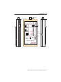
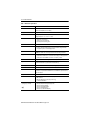
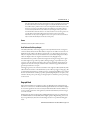
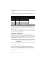
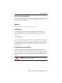
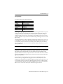
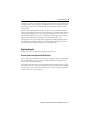
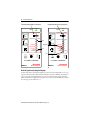
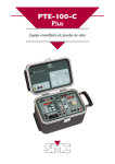
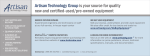
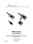
User Manual
ControlNet NetChecker
Catalog Number 1788-CNCHKR
Topic
Page
Important User Information
2
European Communities (EC) Directive Compliance
3
Additional Resources
3
Product Overview
4
Diagnostic Mode
7
Bargraph Mode
9
Operation
11
Reporting Examples
17
Additional Tips
20
Waveform Examples
21
2 ControlNet NetChecker
Important User Information
Solid-state equipment has operational characteristics differing from those of electromechanical equipment. Safety Guidelines for the
Application, Installation and Maintenance of Solid State Controls (publication SGI-1.1 available from your local Rockwell Automation
sales office or online at http://www.rockwellautomation.com/literature/) describes some important differences between solid-state
equipment and hard-wired electromechanical devices. Because of this difference, and also because of the wide variety of uses for
solid-state equipment, all persons responsible for applying this equipment must satisfy themselves that each intended application of
this equipment is acceptable.
In no event will Rockwell Automation, Inc. be responsible or liable for indirect or consequential damages resulting from the use or
application of this equipment.
The examples and diagrams in this manual are included solely for illustrative purposes. Because of the many variables and
requirements associated with any particular installation, Rockwell Automation, Inc. cannot assume responsibility or liability for actual
use based on the examples and diagrams.
No patent liability is assumed by Rockwell Automation, Inc. with respect to use of information, circuits, equipment, or software
described in this manual.
Reproduction of the contents of this manual, in whole or in part, without written permission of Rockwell Automation, Inc., is
prohibited.
Throughout this manual, when necessary, we use notes to make you aware of safety considerations.
WARNING: Identifies information about practices or circumstances that can cause an explosion in a hazardous
environment, which may lead to personal injury or death, property damage, or economic loss.
ATTENTION: Identifies information about practices or circumstances that can lead to personal injury or death,
property damage, or economic loss. Attentions help you identify a hazard, avoid a hazard and recognize the
consequences.
SHOCK HAZARD: Labels may be on or inside the equipment, for example, a drive or motor, to alert people that
dangerous voltage may be present.
BURN HAZARD: Labels may be on or inside the equipment, for example, a drive or motor, to alert people that
surfaces may reach dangerous temperatures.
IMPORTANT Identifies information that is critical for successful application and understanding of the product.
Rockwell Automation Publication 1788-UM001B-EN-P - August 2012
ControlNet NetChecker 3
European Communities (EC) Directive Compliance
If this product has the CE mark, it is approved for installation within the European Union and
EEA regions and has been designed and tested to meet the following directive.
EMC Directive
This product is tested to meet the Council Directive 89/336/EC Electromagnetic
Compatibility (EMC) by applying the following standards, in whole or in part, documented in a
technical construction file:
• EN 50081-2 EMC—Generic Emission Standard, Part 2—Industrial Environment
• EN 50082-2 EMC—Generic Immunity Standard, Part 2—Industrial Environment
This product is intended for use in an industrial environment.
Additional Resources
These documents contain additional information concerning related products from Rockwell
Automation.
Resource
Description
Industrial Automation Wiring and Grounding
Guidelines, publication 1770-4.1
Provides general guidelines for installing a Rockwell Automation industrial
system.
Product Certifications website, http://www.ab.com
Provides declarations of conformity, certificates, and other certification
details.
You can view or download publications at http://www.rockwellautomation.com/literature/.
To order paper copies of technical documentation, contact your local Allen-Bradley distributor
or Rockwell Automation sales representative.
Rockwell Automation Publication 1788-UM001B-EN-P - August 2012
4 ControlNet NetChecker
Product Overview
The 1788-CNCHKR NetChecker is a hand-held tool for testing active ControlNet networks. It
is pocket-sized and battery-powered for field use. The NetChecker helps commissioning and
troubleshooting ControlNet installations by verifying signals on the ControlNet cabling. For
example, installers are able to find shorts and termination faults by using the NetChecker. The
tool is designed to evaluate the quality of the signal on the coaxial medium. It does not interpret
the content of messages, except for the addresses of the nodes issuing messages.
The NetChecker checks several electrical characteristics of the signal:
•
•
•
•
•
•
•
Level of distortion
Noise or signal reflections
Rising and falling edges
Minimum message duration
Minimum between-message duration
Peak-to-peak amplitude
Violations to Manchester signal encoding
An evaluation of the signal quality is made using a combination of criteria on all the above
characteristics. Most of the criteria used are fixed by design and therefore cannot be modified by
the user. The input signal from the network is converted to a 2-level digital signal using a voltage
reference. This voltage reference (or threshold) is the only criteria that can be modified by the
user by means of a slide switch (SW3). The results of the signal analysis are displayed by bi-color
status indicators.
Additional features include a Node Finder and an oscilloscope output. The Node Finder detects
the presence of a given node on the network. The user enters the node address on thumbwheel
switches. The oscilloscope output provides a trigger and an electrically isolated network signal
for displaying messages from a specified node on an oscilloscope.
The NetChecker is designed to be connected to a network via either a standard tap or the
provided BNC T and cable. The NetChecker is a passive instrument. It does not send any signal
on the network under test.
Rockwell Automation Publication 1788-UM001B-EN-P - August 2012
ControlNet NetChecker 5
BNC Connector
SW1 (on the side)
TRAFFIC
INPUT
Low Bat
;
Output to Scope
Signal (x1/4)
GND
Trigger
Power Switch
Diagnostic
L M H
0
7
SW3
Threshold
Node On Line
7 Max
6
OFF
ON
Push ON
Node Finder
Bargraph
5
Slow Edges
4
Illegal Framing
3
Poor Signal
Quality
2
Pass/Fail
Input
Jack
1 Min
SW2
Push ON
Buzzer
Ext
Power
5VDC
0.25A
ControlNetTM NetChecker
Allen-Bradley
Left
Rockwell
Automation
1788-CNCHKR ControlNet NetChecker
Right
Rockwell Automation Publication 1788-UM001B-EN-P - August 2012
6 ControlNet NetChecker
Table 1 - NetChecker Specifications
Attribute
1788-CHNHKR
Dimensions
152 x 83 x 33.5 mm (BNC connector not included)
164 x 83 33.5 mm (BNC connector included)
Weight (with batteries)
250 grams (8.18 oz.)
Environmental
Operating Temperature: 0…50 °C (32…122 °F)
Storage Temperature: -40…85 °C (-40…185 °F)
Slide switch SW1
3-position power switch:
• OFF disconnects the batteries.
• ON turns on the tool permanently.
• Push ON provides momentary power.
Push switch SW2
Momentary switch to turn on the instrument when SW1 is in the Push ON position.
Slide switch SW3
4-position function switch:
• Positions L, M, H select the Diagnostic mode and low, medium and high thresholds.
• The rightmost position selects the Bargraph mode.
BNC connector
Signal input. Connects to the network trunk cable via a standard tap or the provided cable
and BNC T. The NetChecker is electrically isolated from the network by a transformer.
Display
8 bi-color (Red/Green) status indicators:
• Status indicators numbered 1 to 7 are dual-function for Diagnostic or Bargraph modes.
• Status indicators named TRAFFIC also indicates a low battery condition.
Thumbwheel switches
2-digit decimal switches for entering the address of the Node to find (0 to 99).
DC jack
External DC power from AC adapter (nominal 5V DC, max 5.5V @ 0.25A). Jack should have
3.5 mm external diameter (+) and 1.35 mm internal diameter (-).
Oscilloscope connector
3-pin Phoenix connector with Network, Ground, and Trigger signals.
Buzzer
Piezo Buzzer provides an audible indication of detected faults.
Batteries
2 alkaline batteries 1.5V AA/LR6 size located in the battery compartment on the back of the
tool. Batteries are provided uninstalled with the tool. A screwdriver is required to install or
replace the batteries.
Battery life
6 hours continuous use
Accessories
•
•
•
•
3-pin plug connector to fit in the oscilloscope output
BNC T connector
BNC male to BNC female coaxial cable (1 meter long)
User Manual 1788-UM001
Agency certification (when product
or packaging is so marked)
•
•
•
•
•
•
EN 55011, Radiated Emission Class A
ENV 50204, Radiated immunity from digital radio
IEC 1000-4-2, ESD susceptibility
IEC 1000-4-3, Radiated immunity
IEC 1000-4-4, EFT/B immunity
IEC 1000-4-6, conducted RF immunity
Rockwell Automation Publication 1788-UM001B-EN-P - August 2012
ControlNet NetChecker 7
TRAFFIC Status Indicator
This bi-color status indicator at the top of the instrument has two functions:
• Green (network activity)—When the NetChecker is connected to an active network
and powered on this status indicator will turn green to indicate there is activity on the
network. Only messages in which a Start Delimiter is detected in the header (and thus
are considered valid) can cause this status indicator to turn green.
• Red (low battery)—If the batteries are low the status indicator will turn red, whether or
not the tool is connected to a network.
Modes of Network Analysis
The NetChecker offers two modes of analysis to evaluate a network:
• Diagnostic mode—Provides a global network evaluation. It is selected when slide
switch SW3 is in the L, M, or H position.
• Bargraph mode—Provides a quick view of the signal level on the network, either global
(from all nodes) or from a selected node. It is selected when slide switch SW3 is in its
rightmost position.
Diagnostic Mode
In Diagnostic mode positions L, M, and H on slide switch SW3 select one of three fixed voltage
references (or thresholds) used by the NetChecker to convert the analog input signal to a binary
signal.
Table 2 - Threshold Settings
Sensitivity to Noise
SW3 Position
Reference Voltage (mV)
Volts (peak-to-peak)
Most sensitive
L
300
0.6
Moderately sensitive
M
450
0.9
Least sensitive
H
600
1.2
The L (low) reference voltage setting is the most sensitive to input signal or noise. When the L
position is selected any input signal exceeding +/-300mV will be converted to a logical “1” and
processed by the NetChecker. All input signals between +300mV and -300mV will be converted
to a logical “0” and ignored. Note that this sensitivity range is deliberately set above the absolute
minimum peak-to-peak voltage required by the ControlNet specification (510mVpp).
The M (medium) and H (high) positions provide higher voltage references and less sensitivity as
shown in the table above.
Rockwell Automation Publication 1788-UM001B-EN-P - August 2012
8 ControlNet NetChecker
Status Indicator Functions
When slide switch SW3 is in the Diagnostic (left) area of the front panel, the status indicators
have the following functions:
• Pass/Fail status indicator—Indicates the overall quality of the signal on the coaxial
cable. Green when the input signal is clean, this status indicator will turn progressively
red if one or more of the criteria of quality are violated.
• Poor Signal Quality status indicator —Blinks red when the message signal is distorted
and/or when the between-messages gap is polluted by noise so that the NetChecker is
uncertain if the signal received is a valid message or noise. Distortion and noise are
generally the result of reflections of signal on the cable caused by impedance mismatches.
The Poor Signal Quality fault detection is dependent on the threshold settings L, M, and
H on SW3.
Note that there area number of violations to the Manchester encoding in the ControlNet
frame (in Start and End Delimiters). The NetChecker can detect if there are fewer or
more violations than expected. In the case of very large distortion of the signal the
NetChecker may interpret that there are unexpected violations although the message
was generated correctly by the originator node.
• Illegal Framing status indicator—Blinks red when erratic message detection occurs.
The NetChecker verifies the duration of messages and generates a fault if any message is
shorter than 7 bytes (NULL message length). In addition, the time gap between
messages must not be less than 6 bytes. These errors are generally caused by high noise
level or signal reflection at the end of the messages or during the time gap between
messages. These faults are the result of large impedance mismatches on the network.
This fault detection is dependent on the threshold settings L, M, and H on SW3.
• Slow Edges status indicator—Blinks red when the NetChecker has identified a weak
signal with poor rise/fall times. This may result from high signal attenuation caused by
bad coaxial cable, excessive cable length, or an overloaded network. This fault detection
is not dependent on the threshold settings on SW3.
• Node On Line status indicator—Turns green if a node having the address entered in
the Node Finder is detected on the network and the signal received from it is good. The
status indicator will turn red or appear yellow (rapidly flashing red and green) if the
messages received from this node exhibit one or more of the faults signaled by the fault
status indicators.
Rockwell Automation Publication 1788-UM001B-EN-P - August 2012
ControlNet NetChecker 9
Note that when the Node On Line status indicator is red, it generally does not mean that
the node itself is bad, but rather that the signal received by the NetChecker from this
node is affected by a problem on the network. An impedance mismatch may cause some
nodes to be received as good (Node On Line status indicator green) while others are
received as bad (Node On Line status indicator red). Testing at another point on the
network will show that nodes that were received as bad are now received as good or vice
versa. If a Node really is bad it will appear bad everywhere on the network. The
NetChecker can only rely on the signal it receives at one point on the network. That is
why a network should always be checked at several points.
Buzzer
The Buzzer sounds any time a fault is detected.
Node Finder and Oscilloscope Output
The address (MAC ID) of the message originator is the only information from a message that
can be decoded by the NetChecker. This address is compared to the address entered on the two
thumbwheels (the possible node addresses range from 01 to 99). Depending on the setting of
SW3, the comparator either activates the Node On Line status indicator (Diagnostic mode) or
enables the display of the level of signal received from the node (Bargraph mode).
The Node Finder also provides a synchronization signal for viewing the messages from a given
node with a digital storage oscilloscope (DSO). This signal (trigger) is provided on the 3-pin
connector on the left side of the NetChecker. The connector pin labeled “Signal” delivers the
signal from the network via an input transformer with a 1:4 isolation stage. The NetChecker
ground is provided on the center pin.
The Trigger signal rises at the end of the transmission of the originator address (MAC ID) if the
address matches the number on the thumbwheels (set the oscilloscope trigger to rising edge). We
recommend fastening small pieces of solid copper wire (1 inch long 18-22AWG) to the terminal
block for attachment of the oscilloscope’s probes (preferably high impedance 10:1 probes). Also
remember that the peak-to-peak voltage on the Signal pin is one fourth the peak-to-peak voltage
on the network.
Bargraph Mode
When slide switch SW3 is in its rightmost position, the Bargraph mode is enabled and status
indicators 1 to 7 function as a maximum/minimum signal level indicator. This indicator displays
the level of the signal from the node selected by the Node Finder. When the Node Finder is set
to 00, it provides a global view of the signal level (maximum and minimum) of all the messages
seen on the network.
In Bargraph mode, the Poor Signal Quality and Illegal Framing detections are performed with
the threshold defaulted to M (medium). If Poor Signal Quality or Illegal Framing are detected,
they are signalled only by the buzzer. The Slow Edges detection is not performed in Bargraph
mode.
Rockwell Automation Publication 1788-UM001B-EN-P - August 2012
10 ControlNet NetChecker
Bargraph Scale
The Bargraph is not a precision voltmeter. The status indicators are numbered from 1 (lowest
peak-to-peak voltage or Vpp) to 7 (highest Vpp). Also note that the scale is not linear. The
following table shows the approximate peak-to-peak voltages indicated by each status indicator.
Status Indicator
Vpp Level
Status Indicator GREEN if
Status Indicator RED if
7
9.5
No green state
Signal level > 9.5Vpp
6
7.5
7.5Vpp < signal level < 9.5Vpp
No red state
5
5.75
5.75Vpp < signal level < 7.5Vpp
4
4.5
4.5Vpp < signal level < 5.75Vpp
3
3.25
3.25Vpp < signal level < 4.5Vpp
2
2
2Vpp < signal level < 3.25Vpp
1
0.75
0.75Vpp < signal level < 2Vpp
Signal level < 0.75SVpp
Status indicator 7 will turn red if the signal level exceeds 9.5Vpp. Otherwise, it will be off. Status
indicator 1 can have one of three states: red if the signal input is less than 0.75Vpp, green if the
signal input is between 0.75 and 2Vpp, and off under any other condition. Status indicators 2…6
can only be green or off.
Only two status indicators on the bargraph can be turned on at the same time, one indicating the
maximum level and the other indicating the minimum. If the maximum and the minimum levels
are the same, only one status indicator will turn on.
View a Node Signal Level in Bargraph Mode
To check the signal level from a particular node, set SW3 to the rightmost position and set the
address of the node on the Node Finder thumbwheels. Note that the bargraph indication is the
level seen at the point of test, so a low or high indication does not necessarily mean that the node
itself is faulty. If all of the status indicators are off, the NetChecker does not detect any signal
from a node having the address entered.
IMPORTANT
In networks in which repeaters are used, the level read on the bargraph for nodes that are
behind a repeater, such as on another trunk cable than the one being tested, is the level of
signal from the repeater.
Perform a Global Survey of Signal Levels
To perform a global survey of the signal levels of all messages on a network, set SW3 to its
rightmost position and set the Node Finder thumbwheels to 00. The NetChecker will display
two green status indicators, indicating the strongest and the weakest levels encountered on the
network. The maximum and the minimum levels indicated remain latched until NetChecker
power is cycled.
Rockwell Automation Publication 1788-UM001B-EN-P - August 2012
ControlNet NetChecker 11
Oscilloscope Output in Bargraph Mode
In Node Signal Level Bargraph mode, the oscilloscope output is operational in the same way as in
Diagnostic mode. In Global Bargraph mode, however, no trigger signal is provided since there
can be no ControlNet node at address 00.
Operation
This section describes how to operate your NetChecker device.
Install the Batteries
Use a screwdriver to remove the two screws from the battery cover on the back of the
NetChecker. Install the two 1.5V AA batteries supplied as indicated in the compartment.
Batteries installed incorrectly may damage the instrument. Use only alkaline batteries for
replacement.
Conserve Battery Power
To conserve battery power when using the NetChecker, set power switch SW1 to the Push ON
position, then press and hold the Push ON button for just the time necessary (a few seconds) to
read the status indicators. If you need your hands free, set SW1 to the ON position (middle) so
that the NetChecker remains powered on. Remember to put SW1 back to the OFF position
when you are done.
Use a Wall Adapter to Power the NetChecker
The NetChecker may also be powered by a wall adapter connected to the External Power
connector on the side of the tool. The adapter should produce a regulated 5V DC @ 0.25A
(5.5 volts max). The internal batteries are disconnected when the adapter’s jack is inserted in the
connector. The NetChecker remains operating as long as power is provided (switches SW1 and
SW2 are not active in the external power mode; however, it is better to leave SW1 in the OFF
position).
ATTENTION: Make sure that your adapter is CE compliant and that the system formed by the
NetChecker plus the adapter is also CE compliant.
Rockwell Automation Publication 1788-UM001B-EN-P - August 2012
12 ControlNet NetChecker
Connect to the Network
Connect the NetChecker to the network in one of these ways:
• Use the provided cable and BNC T, as shown in the left example. This method requires
you to break the trunk to install the BNC T, which disrupts a running system. The
BNC T is intended for temporary use only. We do not recommend leaving the BNC T
installed.
• Use the provided BNC T with a 1786-TCAP tap and 1786-BNCP barrel connector, as
shown in the right example. The tap, 1786-TCAP, and 1786-BNCP connector must be
purchased separately. The tap can be left in the system for testing purposes, but the tap
must not be left unconnected. Install a 1786-TCAP on all unused taps.
Provided BNC T
Tap
ControlNet Trunk
ControlNet Trunk
Tap Drop
Provided Cable
1786-TCAP
Provided BNC T
1786-BNCP
TRAFFIC
INPUT
Low Battery
Output to Scope
Signal (x1/4)
GND
Trigger
Diagnostic
L MH
Node Finder
Low Battery
Output to Scope
Signal (x1/4)
GND
Trigger
7 Max
Node On Line
Power Supply
OFF
ON
Push ON
TRAFFIC
INPUT
Bargraph
Threshold
6
5
Power Supply
Stow Edges
4
Illegal Framing
3
OFF
ON
Push ON
Poor Signal
Quality
2
Pass/Fail
Diagnostic
L MH
Bargraph
Threshold
7 Max
Node On Line
6
5
Node Finder
1 Min
Stow Edges
4
Illegal Framing
3
Poor Signal
Quality
2
Pass/Fail
Buzzer
((( (((
( (
1 Min
Push ON
Ext
Power
5VDC
Buzzer
((( (((
0,25A
( (
Control Net™ Net Checker
Push ON
Ext
Power
5VDC
0,25A
Control Net™ Net Checker
NetChecker
3231-M
NetChecker
32320-M
If you do not want to open the network, you can install some free taps for testing. With a
redundant network, you can temporarily disconnect one of a node’s taps from the network and
test from this. Recognize, however, that you are removing a node from the network. Test that
node later from a different location on the network.
Rockwell Automation Publication 1788-UM001B-EN-P - August 2012
ControlNet NetChecker 13
When you press the ON switch, the TRAFFIC status indicator should turn green to indicate
that messages are being detected. The greater the volume of traffic seen on the network, the
brighter the status indicator will be illuminated. If the status indicator remains off, the network is
either inactive or the tested segment of cable is disconnected from the network. Check the cable
and the connectors.
Select Testpoints on the Network
Good diagnostic results verify that the network signal is clean at the point of test only. Because
the defects caused by a single impedance mismatch are variable along the cable and are also
related to the node that is transmitting, a network segment should be tested at several points.
For example, test near the two ends of the cable and at one or more points along the cable,
depending on the cable length and the number of nodes. If repeaters are used, every segment
between repeaters should be checked. On a redundant network, check both of the cables.
The NetChecker can indicate that there is a problem on the tested network, but it cannot
indicate where the problem originated. However, it can help to locate intermittent defects, as
described in Additional Tips on page 20. Keep in mind that the source of a problem may be far
away from the point of analysis.
TIP
A bad diagnostic result does not necessarily mean that the network is not functional. However,
it may require a closer check of system components, such as wiring, component quality,
connectors, and impedance matching.
Network Diagnostics
This section describes procedures for evaluating the quality of the ControlNet network.
How to Begin Checking Your Network
Start checking in Diagnostic mode. You can start checking at any of the three threshold settings
(L, M, and H), but be sure to perform the test at all three settings. Then set SW3 to the bargraph
(rightmost) position and examine the global signal level on the network by setting the Node
Finder thumbwheels to 00.
If you obtained the following results, the NetChecker did not detect any problem at the
testpoint.
Status Indicator
State
TRAFFIC
Green
Pass/Fail
Green
Fault
All Off
Buzzer
Does not sound
Bargraph indication
Within range of 2…6
for all thresholds: L, M, H
Refer to the table in the following section to determine the overall state of your network.
Rockwell Automation Publication 1788-UM001B-EN-P - August 2012
14 ControlNet NetChecker
Faults and Their Origins
The NetChecker checks for Poor Signal Quality, Illegal Framing, and Slow Edges. If a fault is
detected when checking in the Diagnostic mode, the buzzer will sound and one or more of the
three fault status indicators will blink red.
The detection of Poor Signal Quality and Illegal Framing depends on the threshold setting on
SW3. Generally, faults that are detected at the L (Low) threshold level will disappear or be seen
less frequently as the threshold is increased. However, in some cases where the received signal has
a low level (less than 2 on the bargraph scale), faults may appear or their recurrence may increase
as the threshold is raised.
Use the table below as a guideline when evaluating your network.
Threshold (SW3)
L
M
H
No fault
No fault
No fault
Very clean
Fault
No fault
No fault
Clean, acceptable
Fault
Fault
No fault
May be acceptable after cabling inspection
Fault
Fault
Fault
Network needs inspection
IMPORTANT
Network quality at the point of test
If faults are reported for all three threshold levels, then it is highly probable that there is a
severe problem on the network.
The third type of fault detection, Slow Edges, checks for a low signal with poor rising and falling
edges caused by an abnormal attenuation of the signal. This fault detection is not dependent on
the threshold setting of SW3.
When analyzing a network, the NetChecker indication may differ from one point of test to
another. A network may be acceptable if the NetChecker reports faults with a low (or even
medium) threshold setting at some points, but a network that exhibits faults everywhere should
be inspected.
Try to evaluate residual problems using the Node Finder and an oscilloscope to ensure that the
signals meet the ControlNet requirements. Examine the nodes that are reported faulted (the
Node On Line status indicator appears red or yellow) and analyze the messages: the faults may
come from signal distortion, signal weakness, poor edges, noise, or signal reflections.
TIP
Remember that the purpose of the NetChecker is to alert for possible problems with network
cabling and that its sensitivity is greater than required by the ControlNet specification.
Rockwell Automation Publication 1788-UM001B-EN-P - August 2012
ControlNet NetChecker 15
Poor Signal Quality
Poor Signal Quality has the following indications.
Status Indicator
State
TRAFFIC
Green
Slow Edges
May also be blinking red
Illegal Framing
May also be blinking red
Poor Signal Quality
Blinking red
Pass/Fail
Yellow or red
Buzzer
Sounds
A blinking Poor Signal Quality status indicator often indicates that signal reflections are present
on the network. If you receive this indication, check the network for impedance mismatches:
inadequate coaxial cable used for all or part of the trunk cable, no termination or wrong
termination, high contact resistance, or intermittent contact in BNC connectors near the taps.
Generally, the faults are reported at the lower threshold settings and disappear or decrease at the
higher settings.
Use the Bargraph mode to verify the minimum signal level. If the signal level is low (2 or less on
the bargraph scale), check the trunk cable length versus the number of nodes and compare it to
the ControlNet specification. Terminate any unused taps with a dummy load (1786-TCAP).
Also ensure that no BNC connector is in contact with any conductive material such as a metal
wireway or DIN rail.
IMPORTANT
An unused drop cable should be terminated by a dummy load (1786-TCAP). Do not use a
75 ohm termination along with a bullet connector. The impedance here is not 75 ohms.
In disorders caused by impedance mismatches, Poor Signal Quality may be reported along with
Illegal Framing (and possibly Slow Edges) for all the threshold settings. This indicates large
impedance mismatches caused by an open trunk cable or a short-circuit. In such cases, the Node
Finder may have difficulty detecting the presence of some nodes on the network because of the
high amount of distortion.
In cases where the received signal has a low level (less than 2 on the Bargraph scale) with
distortion and/or poor edges, the faults may appear or their recurrence may increase as the
threshold is increased. Make sure that the cable length versus number of nodes does not exceed
the ControlNet specification. Check for possible high signal attenuation caused by inadequate
coaxial media used for the trunk cable or segments. High resistance at the contact points of the
BNC connectors on the trunk cable may also add abnormal signal attenuation.
Rockwell Automation Publication 1788-UM001B-EN-P - August 2012
16 ControlNet NetChecker
Illegal Framing
Illegal Framing has the following indications.
Status Indicator
State
TRAFFIC
Green
Slow Edges
May also be blinking red
Illegal Framing
Blinking red
Poor signal Quality
May also be blinking red
Pass/Fail
Yellow or red
Buzzer
Sounds
Illegal Framing occurs if short messages or short between-message gaps have been detected.
Illegal Framing detection is dependent on the threshold setting (SW3). Generally, recurrence
decreases as the threshold is made higher. This fault is often reported along with Poor Signal
Quality.
Illegal Framing most likely indicates a high level of signal reflections on the network (see
previous section), but can also be caused by a faulty node. A faulty node can be suspected in these
scenarios:
• Only Illegal Framing is reported.
• It is not affected by the threshold setting.
• The fault is reported everywhere on the network but the bargraph shows correct signal
levels.
In this case, try to identify the node with the Node Finder. Check the Node On Line status
indicator for each of the known addresses of your network. The faulty node is signalled by the
Node On Line status indicator turning red.
Slow Edges
Slow Edges has the following indications.
Status Indicator
State
TRAFFIC
Green
Slow edges
Blinking red
Illegal Framing
May also be blinking red
Poor signal Quality
May also be blinking red
Pass/Fail
Yellow or red
Buzzer
Sounds
Rockwell Automation Publication 1788-UM001B-EN-P - August 2012
ControlNet NetChecker 17
Slow Edges is generally reported when a weak input signal with poor (slow) rising/falling edges is
identified. This may occur with signals received from remote stations on long networks with a
large number of nodes. In this case, Slow Edges detection is not influenced by the threshold
setting on SW3.
Make sure that the cable length versus number of nodes meets the ControlNet specification.
Check for possible high signal attenuation caused by inadequate coaxial media used for the trunk
cable or segments. High resistance at the contact points of the BNC connectors on the trunk
cable may add abnormal signal attenuation. A small amount of Slow Edges can be tolerated on
long networks provided that the bargraph shows that the minimum level is correct.
Slow Edges may also be reported along with Poor Signal Quality and Illegal Framing in the case
of strong impedance mismatches on the network causing a high amount of distortion. In this
situation, the threshold setting may influence the recurrence of the faults.
Reporting Examples
The figures below show examples of the reporting by the NetChecker.
Check the Signal Level by Using the Threshold Setting
In the example at left, the NetChecker reports no fault at the highest sensitivity (low threshold).
The network is OK at the point of test. The status indicator Node On Line is green because
there is a node transmitting at address 07.
The example at right shows faults reported at High Threshold. Generally, this indicates a high
level of reflections on the network: the network may not be correctly terminated, is accidentally
open or shorted, or there is bad contact in a BNC connector. The status indicator Node On Line
is Off because there is no node at address 11.
Rockwell Automation Publication 1788-UM001B-EN-P - August 2012
18 ControlNet NetChecker
High Threshold Setting (lowest sensitivity level)
Low Threshold Setting (highest sensitivity level)
TRAFFIC
TRAFFIC
INPUT
INPUT
Low Bat
Output to Scope
Signal (x1/4 )
GND
Trigger
Power Switch
Diagnostic
Bargraph
Signal (x1/4 )
GND
Trigger
Threshold
Node On Line
7 Max
6
Node On Line
7 Max
6
5
4
Illegal Framing
3
Illegal Framing
3
Poor Signal
Quality
2
Poor Signal
Quality
2
Slow Edges
Blinking Red
1
Green
1
1 Min
Pass/Fail
Red
Push ON
Buzzer
Ext
Power
5VDC
0.25A
Rockwell
Automation
4
Node Finder
ControlNetTM NetChecker
Allen-Bradley
Allen-
Bargraph
Threshold
OFF
ON
Push ON
5
Pass/Fail
Buzzer
Power Switch
Green
Diagnostic
L M H
Slow Edges
Node Finder
7
Output to Scope
L M H
OFF
ON
Push ON
0
Low Bat
1 Min
Push ON
Ext
Power
5VDC
0.25A
ControlNetTM NetChecker
Allen-Bradley
Allen-
Rockwell
Automation
Check the Signal Level by Using the Bargraph
Set slide switch SW3 to its bargraph (rightmost) position and set the Node Finder to zero to get
a global level indication. Press the ON switch and make sure that the TRAFFIC status indicator
is green. Generally, the bargraph displays two green status indicators indicating the maximum
and the minimum level of signal seen at the point of test on the network. Normally, these should
be in the range of status indicators 2…6.
Rockwell Automation Publication 1788-UM001B-EN-P - August 2012
ControlNet NetChecker 19
TRAFFIC
TRAFFIC
INPUT
INPUT
Low Bat
Low Bat
Output to Scope
Signal (x1/4 )
GND
Trigger
Power Switch
Diagnostic
Bargraph
L M H
Signal (x1/4 )
GND
Trigger
Threshold
Node On Line
7 Max
6
OFF
ON
Push ON
0
Node Finder
Illegal Framing
3
Poor Signal
Quality
2
Pass/Fail
Buzzer
1
1 Min
Push ON
Node On Line
7 Max
6
5
4
Illegal Framing
3
Poor Signal
Quality
2
1 Min
Push ON
Ext
Power
5VDC
0.25A
ControlNetTM NetChecker
Rockwell
Automation
Bargraph: Global Mode
Threshold
Pass/Fail
Buzzer
Ext
Power
5VDC
0.25A
ControlNetTM NetChecker
Allen-Bradley
Allen-
2
Bargraph
L M H
Slow Edges
4
Node Finder
0
Power Switch
Diagnostic
OFF
ON
Push ON
5
Slow Edges
Output to Scope
AllenAllen-Bradley
Rockwell
Automation
Bargraph: Node Level
If status indicator 1 is green, the minimum level is between 0.75Vpp and 2Vpp (this is still
acceptable). If status indicator 1 is red, however, at least one signal is being received at a level less
than 750mVpp. To identify the nodes that are producing the low signals scan all of the node
addresses on the network with the Node Finder. If it is necessary to ensure that the signal at each
node input meets the ControlNet Receive Mask specification (510mVpp at minimum), verify
the minimum level with an oscilloscope connected to the NetChecker.
If status indicator 7 (top of the scale) turns red, a level of signal greater than 9.5Vpp was detected.
This may indicate a strong mismatch on the network. Check if terminations are present.
Rockwell Automation Publication 1788-UM001B-EN-P - August 2012
20 ControlNet NetChecker
Additional Tips
Use these tips to troubleshoot intermittent problems and maintain continuous network
monitoring.
Intermittent Problems
Various intermittent problems are often are caused by the BNC connectors on the trunk cable,
such as the center pin not crimped causing an unreliable contact. The NetChecker in Diagnostic
mode is a valuable tool to help locate such problems. Read the NetChecker while subjecting each
trunk connector or tap to a moderate mechanical stress. If faults are reported, the BNC
connector has not been mounted correctly and must be replaced.
Continuous Network Monitoring
To provide continuous monitoring, the NetChecker powered by an AC wall adapter can be
installed temporarily or permanently on the network. The NetChecker will signal immediately
any degradation of the signal quality at the media level even if the network is still performing
correctly. The NetChecker should be set in Diagnostic mode.
Rockwell Automation Publication 1788-UM001B-EN-P - August 2012
ControlNet NetChecker 21
Waveform Examples
This section shows the types of waveforms that may be seen on a ControlNet network.
Ideal Transmitted Packet on ControlNet Network (as seen at transmitting node)
5 Mbps, Manchester Encoded
Transmit Level: 8.2Vpp +/-1.3V
+V
0V
Tx Off
-V
t
One Bit Time
200nS
Waveform on Cable
Ideal Received Packet on ControlNet Network (as seen at receiving node)
100nS
0 Volt
510mVpp
min.
40nS max jitter
Receive Mask
Rockwell Automation Publication 1788-UM001B-EN-P - August 2012
22 ControlNet NetChecker
Typical Waveforms
Good Signal
Small Amount of
Reflection
Remote
Station
6.000 V/D
100 nS/D
Example of Waveform Seen When Network Is Improperly Terminated
2.000 V/D
500 ns/DIV
Rockwell Automation Publication 1788-UM001B-EN-P - August 2012
ControlNet NetChecker 23
Impedance mismatches cause reflections on the media:
• Network not correctly terminated.
• Impedance of coaxial cable not equal to 75 Ω.
• High resistance of contact in connectors.
• Incorrect network architecture.
IMPORTANT
Each coaxial segment must be terminated with a 1786-TCAP terminator at each end.
Effect of Attenuation on Signal Edges
2.000 V/D
100 ns/DIV
Excessive attenuation causes loss of signal:
• Poor quality coaxial cable
– Resistance too high
– Losses in dielectric
• Overloaded network
– Too long trunk segment
– Excessive number of nodes per segment
• Impedance mismatches
Rockwell Automation Publication 1788-UM001B-EN-P - August 2012
Rockwell Automation Support
Rockwell Automation provides technical information on the Web to assist you in using its products.
At http://www.rockwellautomation.com/support, you can find technical manuals, technical and application notes, sample code and
links to software service packs, and a MySupport feature that you can customize to make the best use of these tools. You can also visit
our Knowledgebase at http://www.rockwellautomation.com/knowledgebase for FAQs, technical information, support chat and
forums, software updates, and to sign up for product notification updates.
For an additional level of technical phone support for installation, configuration and troubleshooting, we offer TechConnectsm support
programs. For more information, contact your local distributor or Rockwell Automation representative, or visit
http://www.rockwellautomation.com/support/.
Installation Assistance
If you experience a problem within the first 24 hours of installation, please review the information that's contained in this manual.
You can also contact a special Customer Support number for initial help in getting your product up and running.
United States or Canada
1.440.646.3434
Outside United States or
Canada
Use the Worldwide Locator at
http://www.rockwellautomation.com/support/americas/phone_en.html, or contact your local
Rockwell Automation representative.
New Product Satisfaction Return
Rockwell Automation tests all of its products to ensure that they are fully operational when shipped from the manufacturing facility.
However, if your product is not functioning and needs to be returned, follow these procedures.
United States
Contact your distributor. You must provide a Customer Support case number (call the phone number
above to obtain one) to your distributor to complete the return process.
Outside United States
Please contact your local Rockwell Automation representative for the return procedure.
Documentation Feedback
Your comments will help us serve your documentation needs better. If you have any suggestions on how to improve this document,
complete this form, publication RA-DU002, available at http://www.rockwellautomation.com/literature/.
Allen-Bradley, Rockwell Software, Rockwell Automation, and TechConnect are trademarks of Rockwell Automation, Inc.
Trademarks not belonging to Rockwell Automation are property of their respective companies.
Rockwell Otomasyon Ticaret A.Ş., Kar Plaza İş Merkezi E Blok Kat:6 34752 İçerenköy, İstanbul, Tel: +90 (216) 5698400
Publication 1788-UM001B-EN-P - August 2012
Supersedes Publication 1788-UM001A-US-P - November 1999
PN-165196
Copyright © 2012 Rockwell Automation, Inc. All rights reserved. Printed in the U.S.A.