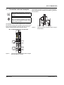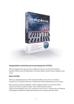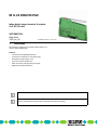
1
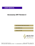
IB IL 24 DO8/HD-PAC
Inline digital output terminal, 8 outputs,
24 V DC, 500 mA
AUTOMATION
Data sheet
7985_en_02
1
© PHOENIX CONTACT 2011-01-06
Description
The terminal is designed for use within an Inline station. It is
used to output digital signals.
Features
–
–
–
–
–
–
Connections for eight digital actuators
Connection of actuators in 1-wire technology
Nominal current per output: 0.5 A
Total current of the terminal: 4 A
Short-circuit and overload protected outputs
Diagnostic and status indicators
This data sheet is only valid in association with the IL SYS INST UM E user manual.
Make sure you always use the latest documentation.
It can be downloaded from the product at www.phoenixcontact.net/catalog.
IB IL 24 DO8/HD-PAC
2
Table of contents
1
Description .............................................................................................................................. 1
2
Table of contents ..................................................................................................................... 2
3
Ordering data .......................................................................................................................... 3
4
Technical data ......................................................................................................................... 3
5
Additional tables ...................................................................................................................... 6
6
Internal circuit diagram ............................................................................................................ 6
7
Local status and diagnostic indicators ..................................................................................... 7
8
Terminal point assignment....................................................................................................... 7
9
Connection notes and examples ............................................................................................. 8
10
Application examples .............................................................................................................. 9
11
Process data............................................................................................................................ 9
7985_en_02
PHOENIX CONTACT
2
IB IL 24 DO8/HD-PAC
3
Ordering data
Description
Order No.
Pcs./Pkt.
Inline digital output terminal, complete with accessories (connector and la- IB IL 24 DO8/HD-PAC
beling field), 8 outputs, 24 V DC, 500 mA, single-wire connection method
Type
2700172
1
Accessories
Type
Order No.
Pcs./Pkt.
Connector, for digital 1, 2 or 8-channel Inline terminals ( Plug/Adapter )
IB IL SCN-8
2726337
10
Labeling field, width: 12.2 mm ( Marking )
IB IL FIELD 2
2727501
10
Inline terminal for power distribution (GND), complete with accessories,
(connector and labeling field) connections for GND
IB IL PD GND-PAC
2862990
1
VARIOFACE front adapter for 8-channel Inline HD modules
( Plug/Adapter )
FLKM 14-PA-INLINE/DIO8
2900889
1
Documentation
Type
Order No.
Pcs./Pkt.
User manual, English, Automation terminals of the Inline product range
IL SYS INST UM E
-
-
Data sheet, English,
INTERBUS addressing
DB GB IBS SYS ADDRESS
-
-
4
Technical data
Dimensions (nominal sizes in mm)
140,5
71,5
119,8
Width
12.2 mm
Height
119.8 mm
Depth
71.5 mm
Note on dimensions
Housing dimensions
General data
Color
Green
Weight
60 g ( With connector )
Operating mode
Process data mode with one byte
Ambient temperature (operation)
-25 °C ... 55 °C
Ambient temperature (storage/transport)
-25 °C ... 85 °C
Permissible humidity (operation)
10 % ... 95 % (according to DIN EN 61131-2)
Permissible humidity (storage/transport)
10 % ... 95 % (according to DIN EN 61131-2)
Air pressure (operation)
70 kPa ... 106 kPa (up to 3000 m above sea level)
7985_en_02
PHOENIX CONTACT
3
IB IL 24 DO8/HD-PAC
General data
Air pressure (storage/transport)
70 kPa ... 106 kPa (up to 3000 m above sea level)
Degree of protection
IP20
Protection class
III, IEC 61140, EN 61140, VDE 0140-1
Connection data
Name
Inline connectors
Type of connection
Spring-cage connection
Conductor cross section solid / stranded
0.08 mm² ... 1.5 mm²
Conductor cross section [AWG]
28 ... 16
Interface Inline local bus
Type of connection
Inline data jumper
Transmission speed
500 kbps
Power consumption
Segment supply voltage US
24 V DC (nominal value)
Current consumption from US
max. 4 A DC
Communications power UL
7.5 V DC
Current consumption from UL
max. 45 mA
Power consumption
max. 0.34 W (at UL)
Power loss
max. 0.62 W
Digital outputs
Number of outputs
8
Type of connection
Spring-cage connection
Connection method
1-wire
Output voltage
24 V (US - 1 V)
Maximum output current per channel
500 mA
Maximum output current per device
4A
Nominal load, ohmic
12 W (48 Ω)
Nominal load, inductive
12 VA (1.2 H; 50 Ω)
Nominal load, lamp
12 W
Signal delay when switching on an ohmic nominal load
Typ. 500 µs
Signal delay when switching on an inductive nominal load
Typ. 100 ms (1.2 H; 50 Ω)
Signal delay when switching on a lamp nominal load
Typ. 100 ms
Signal delay when switching off an ohmic nominal load
Typ. 1 ms
Signal delay when switching off an inductive nominal load
Typ. 50 ms (1.2 H; 50 Ω)
Signal delay when switching off a lamp nominal load
Typ. 1 ms
Maximum operating frequency with ohmic nominal load
max. 300 Hz (this switching frequency is limited by the data rate selected, the
number of bus devices, the structure of the bus, the software used and the control
or computer system used)
Maximum operating frequency with inductive nominal load
max. 0.5 Hz
Maximum operating frequency with lamp nominal load
max. 8 Hz (this switching frequency is limited by the data rate selected, the number of bus devices, the structure of the bus, the software used and the control or
computer system used)
Reaction time with short-circuit
ca. 1 s
Reaction time with ohmic overload
ca. 3 s
Behavior at voltage switch-off
The output follows the power supply without delay
One-time unsolicited energy
300 mJ
Limitation of the voltage induced on circuit interruption
-15 V ≤ Udemag ≤ -45.8 V (Udemag = demagnetization voltage)
Output voltage when switched off
max. 1 V
Output current when switched off
max. 300 µA
7985_en_02
PHOENIX CONTACT
4
IB IL 24 DO8/HD-PAC
Digital outputs
Behavior with overload
Auto restart
Restart frequency with ohmic overload
400 Hz
Restart frequency with lamp overload
400 Hz
Behavior with inductive overload
Output can be destroyed
Reverse voltage resistance to short pulses
Reverse voltage proof
Resistance to permanent reverse voltage
max. 500 mA
Overcurrent shut-down
min. 0.7 A
Overload protection, short-circuit protection of outputs
Zener diode in output chip
Programming Data
ID code (hex)
BD
ID code (dec.)
189
Length code (hex)
81
Length code (dec.)
129
Process data channel
8 bits
Input address area
0 bit
Output address area
8 bits
Parameter channel (PCP)
0 bit
Register length (bus)
8 bits
For the programming data/configuration data of other bus systems, please refer to the corresponding electronic device data sheet (e.g., GSD,
EDS).
PROFIBUS telegram data
Required parameter data
3 Byte
Need for configuration data
4 Byte
Error messages to the higher level control or computer system
Short-circuit / overload of the digital outputs
Error message in the diagnostic code (bus) and display (2 Hz) via the LED (D) on
the module
Electrical isolation/isolation of the voltage areas
5 V supply incoming remote bus/7.5 V supply (bus logic)
500 V AC , 50 Hz , 1 min
5 V supply outgoing remote bus/7.5 V supply (bus logic)
500 V AC , 50 Hz , 1 min
7.5 V supply (bus logics)/24 V supply (I/O)
500 V AC , 50 Hz , 1 min
24 V supply (I/O) / functional earth ground
500 V AC , 50 Hz , 1 min
To achieve electrical isolation between the logic level and the I/O area, supply these areas from separate power supply units. Interconnection
of the power supply units in the 24 V area is not permitted (see also user manual).
Approvals
For the latest approvals, please visit www.phoenixcontact.net/catalog.
7985_en_02
PHOENIX CONTACT
5
IB IL 24 DO8/HD-PAC
5
Additional tables
6
Internal circuit diagram
Output characteristic curve when switched on (typical)
Output current (A)
Differential output voltage
(V)
0
0
0.1
0.02
0.2
0.03
0.3
0.04
0.4
0.06
0.5
0.07
Local bus
OPC
UL
16
8
8
4x
4x
US
+24 V (US)
+24 V (UM)
Figure 1
OPC
Internal wiring of the terminal points
Protocol chip
(Bus logic including voltage conditioning)
LED (status indicator)
Optocoupler
Transistor
Digital output
Explanation for other used symbols has been
provided in the IL SYS INST UM E user manual.
7985_en_02
PHOENIX CONTACT
6
IB IL 24 DO8/HD-PAC
7
Local status and diagnostic
indicators
8
Terminal point assignment
D
1
3
5
7
2
4
6
8
D
2
1
4
3
6
5
8
7
Figure 2
Designation
D
1 to 8
1.1
2.1
2.1
1.2
1.2
2.2
2.2
1.3
1.3
2.3
2.3
1.4
1.4
2.4
2.4
1.1
Local status and diagnostic indicators
Color
Meaning
Green
Yellow
Diagnostics (bus and logic voltage)
Status of the outputs
Function identification
Pink
7985_en_02
Figure 3
Terminal point assignment
Terminal point
1.1 / 2.1
1.2 / 2.2
1.3 / 2.3
1.4 / 2.4
Assignment
Signal output (OUT 1 / OUT 2)
Signal output (OUT 3 / OUT 4)
Signal output (OUT 5 / OUT 6)
Signal output (OUT 7 / OUT 8)
PHOENIX CONTACT
7
IB IL 24 DO8/HD-PAC
9
Connection notes and examples
The actuators can also be connected via external busbars.
Ensure that GND of the actuators and GND for US have the
same potential.
When connecting the actuators, observe the
assignment of the terminal points to the process data.
1.1
2.1
1.2
2.2
1.3
2.3
1.4
2.4
OUT2
OUT1
NOTE: Malfunction
GND of the actuators and GND of the supply
voltage US, which supply the actuators, must
have the same potential.
The simplest way to meet this requirement is to use the IB IL
PD GND-PAC terminal. Wire the GND connections for the actuators to these terminals. In this way, they are connected
with the potential jumper GND of the Inline station.
Figure 5
IB IL 24 DO8/HD-PAC IB IL PD GND-PAC
OUT7
OUT8
Typical connection of actuators when using external busbars
D
1
3
5
7
OUT1
OUT7
Figure 4
2
4
6
8
PD GND
1.1
2.1
1.1
2.1
1.2
2.2
1.2
2.2
1.3
2.3
1.3
2.3
1.4
2.4
1.4
2.4
OUT2
OUT8
Typical connection of actuators when using the
IB IL PD GND-PAC terminal
7985_en_02
PHOENIX CONTACT
8
IB IL 24 DO8/HD-PAC
10
Application examples
11
IB IL 24 DO8/HD-PAC
IBS IL 24 BK-T/U-PAC IB IL PD GND-PAC
BA
RD
RC
LD
1
3
5
7
UM
BK-T/U
2
4
6
8
PD GND
K1
1.1
2.1
1.1
2.1
1.1
2.1
1.1
2.1
1.1
2.1
1.1
2.1
1.2
2.2
1.2
2.2
1.2
2.2
1.2
2.2
1.2
2.2
1.2
2.2
1.3
2.3
1.3
2.3
1.3
2.3
1.3
2.3
1.3
2.3
1.3
2.3
1.4
2.4
1.4
2.4
1.4
2.4
1.4
2.4
1.4
2.4
1.4
2.4
K2
24 V DC +
(UBK) -
Assignment of the terminal points to the output process
data
(Byte.Bit)
view
Assignment
D
US
UL
Process data
K3
Byte
Byte 0
Bit
7 6 5 4 3 2 1 0
Terminal 2.4 1.4 2.3 1.3 2.2 1.2 2.1 1.1
point
(signal)
Status indi- LED
8 7 6 5 4 3 2 1
cator
For the assignment of the illustrated (byte.bit)
view to your INTERBUS control or computer
system, please refer to the
DB GB IBS SYS ADDRESS data sheet.
+ -
24 V DC
(UM/US)
Connection of contactors when using the IB IL
PD GND-PAC terminal
RD
RC
LD
D
US
UL
1
3
5
7
UM
BK-T/U
1.1
2.1
1.1
2.1
1.1
2.1
1.1
2.1
1.1
2.1
1.2
2.2
1.2
2.2
1.2
2.2
1.2
2.2
1.2
2.2
1.3
2.3
1.3
2.3
1.3
2.3
1.3
2.3
1.3
2.3
1.4
2.4
1.4
2.4
1.4
2.4
1.4
2.4
1.4
2.4
K2
24 V DC +
(UBK) -
2
4
6
8
K1
BA
K3
Figure 6
+ -
24 V DC
(UM/US)
Figure 7
7985_en_02
Connection of contactors when using external
busbars
PHOENIX CONTACT GmbH & Co. KG • 32823 Blomberg • Germany • Phone: +49-(0) 5235-3-00
PHOENIX CONTACT • P.O.Box 4100 • Harrisburg • PA 17111-0100 • USA • Phone: +717-944-1300
www.phoenixcontact.com
9