1
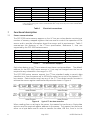
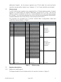
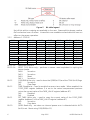
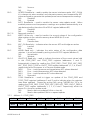
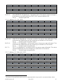
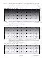
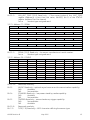
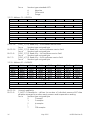
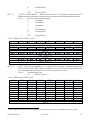
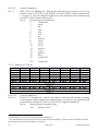
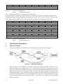
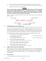
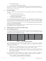
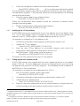
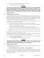
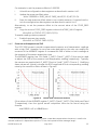
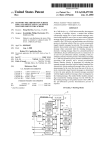
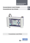
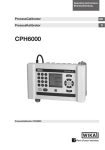
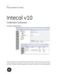
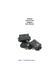
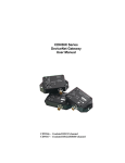
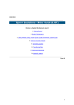
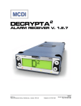
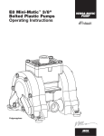
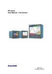
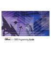
GE Measurement & Control DPS 5000 Series Sensors I2C-bus Pressure Transducer User Manual – K0582 English Druck Ltd., Fir Tree Lane, Groby. Leicester, LE6 0FH, UK. Tel: +44 (0)116 231 7100; Fax +44 (0)116 231 7103 © 2015 General Electric Company. All rights reserved Safety The manufacturer has designed this sensor to be safe when operated using the procedures detailed in this manual. Do not use this sensor for any other purpose than that stated. This manual contains operating and safety instructions that must be followed for safe operation and to maintain the sensor in a safe condition. The safety instructions are either warnings or cautions issued to protect the user and the equipment from injury or damage. Use qualified personnel and good engineering practice for all procedures in this manual. Qualified personnel must have the necessary technical knowledge, documentation, special test equipment and tools to carry out required work on this sensor. Pressure Do not apply pressure greater than the maximum safe working pressure to the sensor. Toxic materials There are no known toxic materials used in the sensor. Maintenance The sensor must be maintained using the manufacturer’s procedures and these should be carried out by authorised service agents or the manufacturer’s service departments. Technical advice EC Directives For technical advice contact the manufacturer. This sensor complies with the requirements of the Pressure Equipment Directive 97/23/EEC and the EMC directive 2004/108/EC1. For further details refer to the Sales Data Sheet or the customer specification drawing. A full conformity certificate is available from the manufacturer. Contact GE Measurement & Control 1 www.gemeasurement.com The EMC directive is only applicable to the external variant (model E503D) K0582 Revision B May 2015 i Abbreviations The following abbreviations are used in this manual. Note: Abbreviations are the same in the singular and plural ADC Analogue to digital converter Addr Address ASCII American standard code for information interchange atm atmosphere ESD Electro-static discharge ftH2O Feet of water hPa HectoPascal Hz Hertz I2C Inter-integrated circuit IEEE Institute of Electrical and Electronic Engineers inHg Inch of Mercury inH2O Inch of water kbit/s Kilobits per second kbyte Kilobytes (1024 bytes) kgf/cm2 Kilogram-force per square centimetre kPa KiloPascal LSB Least significant bit/byte mbar Millibar mH2O Metre of water mmHg Millimetre of Mercury mmH2O Millimetre of water MPa MegaPascal ms Millisecond MSB Most significant bit/byte PCB Printed circuit board psi Pound per square inch s Second SNR Signal to noise ratio °C Degrees Celsius Nomenclature The following number notations are used in this document. 0bn..n Binary number notation, e.g. 0b10 0xn..n Hexadecimal number notation, e.g. 0x3BF0 The following data types are used in this document. Type Unsigned byte Unsigned integer Unsigned word Float Extended ASCII NOTE 1: ii Bits 8 16 32 32 8 Range 0x00 (0) to 0xFF (255) 0x0000 (0) to 0xFFFF (65535) 0x00000000 (0) to 0xFFFFFFFF (4294967295) 0xFF7FFFFF (-3.4028E-38) to 0x7F7FFFFF (+3.4028E+38) NOTE 1 0x00 (NULL) to 0xFF (ÿ) NOTE 2 Data type float to IEEE 754. NOTE 2: Data type Extended ASCII to ISO 8859-1 May 2015 K0582 Revision B References Reference 1 I2C-bus specification and user manual, NPX Semiconductor UM10204 Rev. 6 available from www.nxp.com K0582 Revision B May 2015 iii Contents 1 Introduction 1 1.1 1.2 General Configuration 1 1 2 Installation 2 2.1 2.2 2.3 2.4 General Mounting and orientation Connecting to the pressure source Electrical connections 2 2 2 3 3 Functional description 4 3.1 3.2 3.3 3.3.1 3.3.2 3.3.3 3.3.4 3.3.5 3.3.6 3.3.7 3.3.8 3.3.9 3.3.10 3.3.11 3.3.12 3.3.13 3.3.14 3.3.15 3.3.16 3.3.17 3.3.18 3.3.19 3.3.20 3.3.21 3.3.22 3.3.23 3.3.24 3.3.25 3.3.26 3.3.27 3.3.28 3.3.29 3.3.30 3.3.31 Sensor communication Memory map Register descriptions Register bit table legend Address 0 - STATUS Address 1 – COMP_PRES Address 2 – COMP_TEMP Address 3 – ADC_PRES Address 4 – ADC_TEMP Address 5 – ACCESS Address 6 – MVOLT_PRES Address 7 – MVOLT_TEMP Address 66 – I2C_ADDR Address 67 – COEF_FIT Address 68 – GAIN_ADJ Address 69 – OFFSET_ADJ Address 70 – MAX_RANGE Address 71 – MIN_RANGE Address 72 – CAL_DATE Address 73 – MAX_ADC_PRES Address 74 – MIN_ADC_PRES Address 75 – MAX_ADC_TEMP Address 76 – MIN_ADC_TEMP Address 77 – SERIAL Address 78 – CONFIG Address 79 – VERSION Address 82 – AVERAGE Address 83 – PRES_CONV Address 84 – PRES_UNIT Address 85 – DELAY Address 86 - SPEC_DWG Address 87 – TARE_VALUE Addresses 128-157 - Pressure coefficients Addresses 158-187 - Temperature coefficients iv May 2015 4 5 5 5 6 7 8 8 9 9 9 10 10 11 11 12 12 12 13 13 14 14 14 15 15 16 16 17 17 18 19 19 19 20 K0582 Revision B 4 Operational description 20 4.1 4.2 4.3 4.3.1 4.3.2 4.4 4.4.1 4.4.2 4.4.3 4.4.4 4.4.5 4.4.6 4.4.7 4.4.8 Operational states Reading the pressure and temperature Updating the pressure and temperature Manual update Automatic update Updating the sensor configuration data registers User modifiable registers Modifying the I2C-bus address Changing the auto-update period Changing the unit of pressure Reading relative pressure Pressure and temperature SNR Maximising the update rate Pressure re-calibration 20 21 21 21 22 22 22 23 23 24 24 25 26 26 5 Maintenance 27 5.1 5.2 5.3 5.4 Cleaning Adjustment Repair Disposal 27 28 28 28 Annex A Unit of pressure conversion factors 29 List of figures Figure 1 Figure 2 Figure 3 Figure 4 Figure 5 Figure 6 Figure 7 Figure 8 External and internal DPS 5000 sensors – General view Pressure connection Typical I2C-bus network Typical I2C-bus data transfers Bit table legend Operational states Interaction legend Noise level correction factors 1 3 3 4 6 20 21 25 Electrical connections I2C-bus feature support Memory map User modifiable registers 4 4 5 22 List of tables Table 1 Table 2 Table 3 Table 4 K0582 Revision B May 2015 v Page left intentionally blank vi May 2015 K0582 Revision B 1 Introduction 1.1 General The DPS 5000 series sensor is a microcontroller based smart pressure transducer that provides a digital output through an I2C-bus interface. The sensor is available as either an external or internal variant. The external variant is a sealed device with the electrical connections made via an integral cable. The internal variant is an open frame device with electrical connections made via an integral plug. Figure 1 External and internal DPS 5000 sensors – General view The DPS 5000 series sensors are low powered devices offering a high level of accuracy over a wide temperature range. The I2C-bus interface provides compensated pressure and temperature readings and allows the sensor operation to be software controlled. 1.2 Configuration The following options are available at the time of ordering: a) External or internal sensor variant b) Pressure range c) Pressure connector Each sensor is supplied with the following documentation: d) e) 2 Hazardous area installation instructions2: Document K0546 for the external sensor variant Document K0547 for the internal sensor variant Calibration certificate Only supplied with hazardous area certified sensors K0582 Revision B May 2015 1 2 Installation 2.1 General Before installing the DPS 5000 series sensor: Ensure that the sensor is the correct type for the application and will not be subject to pressures or media outside those specified on the applicable datasheet or specification drawing. If the sensor is being installed in a hazardous area observe the installation instructions given in the supplied document K0546 or K0547. Read all relevant instructions and procedures in the applicable system installation manual. To prevent contamination prior to installation, keep the sensor in the original packaging with all the supplied covers fitted. When installing the internal variant, to prevent possible damage, avoid touching or applying excessive force to the exposed PCB assemblies. WARNING Do not interchange sensors between an oil system and a system that uses fuel or gas. This can cause an explosion resulting in death or injury and/or damage to equipment. High pressures and extremes of temperature are dangerous. De-pressurize and allow components to attain an acceptable temperature in systems where high pressures and high or low temperatures are present. CAUTION The sensor contains ESD sensitive devices. Whilst the sensor incorporates protection against ESD, caution should be taken to observe proper ESD handling procedures when installing the internal variant. 2.2 Mounting and orientation The DPS 5000 series sensors are designed to be mounted in any orientation. However, the sensor is a harsh media isolated product and the isolation is achieved by hermetically sealing the sensor chip within an oil filled chamber. The weight of the oil gives a g-sensitivity as a pressure offset error that may be noticeable at the lowest pressure ranges. Ensure the sensor is mounted in a manner that avoids unwanted mechanical or thermal stress such as vibration, shock or excessive or rapid temperatures excursions. 2.3 Connecting to the pressure source When connecting the pressure source to the sensor, ensure the mating surfaces are correctly sealed. Failure to properly seal may affect the sensor performance or calibration accuracy. Male parallel threaded pressure connectors must not be sealed or constrained against the face at the base of the thread. The forward flat face should be used as shown in Figure 2. 2 May 2015 K0582 Revision B Figure 2 Pressure connection Torque tighten the sensor in accordance with the system installation manual. 2.4 Electrical connections The DPS 5000 series sensors employ a 4 wire I2C-bus user electrical interface: Supply + Serial data (SDA) Serial clock (SCL) Supply – The sensor may be used standalone or as part of a network of compatible I2C-bus devices. CAUTION The DPS 5000 is intended for use within networks operated from a single supply at a voltage within the range 2.7 V to 3.6 V. Operation outside these limits is not guaranteed and may damage the sensor. The sensor interface includes 2 reserved signals. These should be left open circuit as connecting to these signals may result in incorrect sensor operation. Figure 3 Typical I2C-bus network The electrical connections to the sensors are colour coded as shown in Table 1. K0582 Revision B May 2015 3 Signal Supply + Serial data Serial clock Supply Reserved Case NOTE 1: External variant Red Orange Black White Yellow & Blue Screen Internal variant Red Yellow Green Blue Orange & Black - Plug pin NOTE 1 1 2 3 4 5&6 - The mating connector for the internal variant plug is a Molex Milli-GridTM connector system 6 pin crimp housing part number 0511100660 with crimp terminals part number 0503948051 or 0503948100. Table 1 3 Functional description 3.1 Sensor communication Electrical connections The DPS 5000 series sensors appear on the I2C-bus as a slave device containing a number of memory mapped registers that are used to control the operation of the sensor and to provide information about the sensor and its environment. Table 2 summarizes the features of the I2C-bus specification, Reference 1, that are supported by the DPS 5000 series sensors. Feature Standard mode Fast mode Fast mode plus High speed mode 7 bit address Applicability Supported Not supported Not supported Not supported Supported Table 2 Feature 10 bit addressing General call address Clock stretching Software reset Device ID Applicability Not supported Not supported Supported Not supported Not supported I2C-bus feature support Each slave device on an I2C-bus network must have a unique address. The default address for the DPS 5000 series sensors is 2, but may be changed over the bus as required to any value within the range 1 to 127. The DPS 5000 series sensors support the I2C-bus standard mode to permit data transfers to or from the sensor up to 100 kbit/s under the control of the network I 2Cbus master. Data transfers may use any of the 3 I2C-bus data transfer formats to achieve the sensor register read and write protocols shown in Figure 4. Figure 4 Typical I2C-bus data transfers When reading from or writing to the sensor, the master first performs a 1 byte data write to send the required register address to the sensor. The master then performs either an n byte data read or write to transfer the data, LSB first, from or to the 4 May 2015 K0582 Revision B addressed register. As the sensor registers are 32 bits wide, the read and write transfers are generally 4 bytes long. However, 1, 2 or 3 byte transfers are allowed. 3.2 Memory map The DPS 5000 sensor registers are mapped within a 1 kbyte memory space. As each register is 4 bytes wide, the register addresses range from 0 to 255. Not all the address space is available to the user, some addresses are reserved whilst others are unused. The reserved addresses cannot be written to and read as 0x00000000. Unused addresses cannot be written to and read as 0xFFFFFFFF. The registers are grouped into 3 blocks: volatile data, configuration data and coefficient data as shown in Table 3. Volatile data Addr Register 0 STATUS 1 COMP_PRES 2 COMP_TEMP 3 ADC_PRES 4 ADC_TEMP 5 ACCESS 6 MVOLT_PRES 7 MVOLT_TEMP 8 Reserved . . . . . . . . . . . . . . . . . . . . . . . . . . . . . . . . . . . . . . 63 Reserved Configuration data Addr Register 64 Reserved 65 Reserved 66 I2C_ADDR 67 COEF_FIT 68 GAIN_ADJ 69 OFFSET_ADJ 70 MAX_RANGE 71 MIN_RANGE 72 CAL_DATE 73 MAX_ADC_PRES 74 MIN_ADC_PRES 75 MAX_ADC_TEMP 76 MIN_ADC_TEMP 77 SERIAL 78 CONFIG 79 VERSION 80 Reserved 81 Reserved 82 AVERAGE 83 PRES_CONV 84 PRES_UNIT 85 DELAY 86 SPEC_DWG 87 TARE_VALUE 88 Reserved . . . . . . 127 Reserved Table 3 Coefficient data Addr Register 128 . . Up to 30 . pressure . coefficient . registers . . 157 158 . . . Up to 30 . temperature coefficient . registers . . . 187 188 Unused . . . . . . . . . . . . . . . . 255 Unused Memory map 3.3 Register descriptions 3.3.1 Register bit table legend The legend used for the bit tables within this section is shown in Figure 5. K0582 Revision B May 2015 5 Figure 5 Bit table legend Not all bits within a register are available to the user. Reserved bits always read as 0b0 and writes have no effect. Unused bits are readable and writable but have no effect on the sensor operation. 3.3.2 Address 0 - STATUS Bit 31 Bit 30 Reserved Reserved R-0 R-0 Bit 23 Bit 22 Reserved Reserved R-0 R-0 Bit 15 Bit 14 RESET [1..0] W-0 W-0 Bit 7 Bit 6 Reserved Reserved R-0 R-0 Bit 31–16 Bit 15–14 Bit 13 Bit 12 Bit 11 Bit 10 6 Bit 29 Reserved R-0 Bit 21 Reserved R-0 Bit 13 CLRQERR W-0 Bit 5 WRITE W-0 Bit 28 Reserved R-0 Bit 20 Reserved R-0 Bit 12 TARE R/W-0 Bit 4 ADC_ON R-X Bit 27 Reserved R-0 Bit 19 Reserved R-0 Bit 11 SET_TARE W-0 Bit 3 WENB R-0 Bit 26 Bit 25 Reserved Reserved R-0 R-0 Bit 18 Bit 17 Reserved Reserved R-0 R-0 Bit 10 Bit 9 QERR INTRDG R-0 RW-0 Bit 2 Bit 1 VALID [1..0] R-X R-X Bit 24 Reserved R-0 Bit 16 Reserved R-0 Bit 8 AUTO R/W-0 Bit 0 CONV R/W-X Reserved, read as 0 RESET [1..0]: Write only - performs a sensor reset equivalent to cycling the sensor power. 0b00 No action 0b01 No action 0b10 Reset 0b11 No action CLRQERR: Write only - used to clear the QERR (bit 10) and the CONV (bit 0) flags. 0b0 No action 0b1 Clear flags TARE: Read/write – used to enable the sensor tare mode. When enabled, the COMP_PRES register (address 1) is set to the actual compensated pressure minus the current value of the TARE_VALUE register (address 87). 0b0 Disabled 0b1 Enabled SET_TARE: Write only – used to copy the current value of the COMP_PRES register (address 1) to the TARE_VALUE register (address 87). 0b0 No action 0b1 Copy data QERR: Read only - set when an internal queue error is detected whilst AUTO (bit 8) is set. Reset using CLRQERR (bit 13). May 2015 K0582 Revision B 0b0 No error 0b1 Error INTRDG: Read/write – used to enable the sensor interleave mode. ADC_ON (bit 4) is always set when enabled, and alternate pressure and temperature ADC values are used to generate the updated pressure and temperature readings. 0b0 Disabled 0b1 Enabled AUTO: Read/write – used to enable the sensor auto-update mode. When enabled pressure and temperature readings are updated automatically at a rate determined by the value of the DELAY register (address 85). 0b0 Disabled 0b1 Enabled Reserved, read as 0 WRITE: Write only – used to transfer the current values of the configuration data registers to non-volatile memory when WENB (bit 3) is set. 0b0 No action 0b1 Transfer data ADC_ON: Read only – indicates when the sensor ADC and bridge are active. 0b0 Inactive 0b1 Active WENB: Read only – indicates the write status of the configuration data resisters. It is set and cleared by writing to the ACCESS register (address 5). 0b0 Not writable 0b1 Writable VALID[1..0]: Read only – used to indicate the status of the current values held in the COMP_PRES and COMP_TEMP registers (addresses 1 and 2). Automatically cleared by reading the COMP_PRES, COMP_TEMP, ADC_PRES, ADC_TEMP, MVOLT_PRES or MVOLT_TEMP register (addresses 1, 2, 3, 4, 6 and 7 respectively) whilst the sensor is in the auto-update mode. 0b00 Error – invalid pressure and temperature ADC values detected 0b01 Error – invalid temperature ADC value detected 0b10 Error – invalid pressure ADC value detected 0b11 Data valid CONV: Read/write – used to trigger an update of the COMP_PRES and COMP_TEMP registers (addresses 1 and 2) and to indicate when the registers have been updated. Cleared by writing 0b0, using CLRQERR (bit 13) or by reading the COMP_PRES, COMP_TEMP, ADC_PRES, ADC_TEMP, MVOLT_PRES or MVOLT_TEMP register (addresses 1, 2, 3, 4, 6 and 7 respectively) whilst the sensor is in the auto-update mode. 0b0 Read = data not updated / Write = clear bit 0b1 Read = data updated / Write = request update Bit 9 Bit 8 Bit 7–6 Bit 5 Bit 4 Bit 3 Bit 2–1 Bit 0 3.3.3 Address 1 – COMP_PRES Bit 31 Bit 30 Bit 29 Bit 23 Bit 22 Bit 21 K0582 Revision B Bit 28 Bit 27 COMP_PRES [31..24] R-X Bit 20 Bit 19 COMP_PRES [23..16] R-X May 2015 Bit 26 Bit 25 Bit 24 Bit 18 Bit 17 Bit 16 7 Bit 15 Bit 14 Bit 13 Bit 7 Bit 6 Bit 5 Bit 31–0 3.3.4 Bit 9 Bit 8 Bit 2 Bit 1 Bit 0 Address 2 – COMP_TEMP Bit 30 Bit 29 Bit 23 Bit 22 Bit 21 Bit 15 Bit 14 Bit 13 Bit 7 Bit 6 Bit 5 Bit 31–0 Bit 28 Bit 27 COMP_TEMP [31..24] R-X Bit 20 Bit 19 COMP_TEMP [23..16] R-X Bit 12 Bit 11 COMP_TEMP [15..8] R-X Bit 4 Bit 3 COMP_TEMP [7..0] R-X Bit 26 Bit 25 Bit 24 Bit 18 Bit 17 Bit 16 Bit 10 Bit 9 Bit 8 Bit 2 Bit 1 Bit 0 COMP_TEMP [31..0]: Read only – the most recently updated compensated temperature value in °C. Reading this register whilst the sensor is in the autoupdate mode will clear the CONV (bit 0) flag of the STATUS register (address 0). 0xn..n Number type float Address 3 – ADC_PRES Bit 31 Bit 30 Bit 29 Bit 23 Bit 22 Bit 21 Bit 15 Bit 14 Bit 13 Bit 7 Bit 6 Bit 5 Bit 31–0 8 Bit 10 COMP_PRES [31..0]: Read only – the most recently updated compensated pressure value in the pressure units defined by the PRES_UNIT register (address 84). Reading this register whilst the sensor is in the auto-update mode will clear the CONV (bit 0) flag of the STATUS register (address 0). 0xn..n Number type float Bit 31 3.3.5 Bit 12 Bit 11 COMP_PRES [15..8] R-X Bit 4 Bit 3 COMP_PRES [7..0] R-X Bit 28 Bit 27 ADC_PRES [31..24] R-X Bit 20 Bit 19 ADC_PRES [23..16] R-X Bit 12 Bit 11 ADC_PRES [15..8] R-X Bit 4 Bit 3 ADC_PRES [7..0] R-X Bit 26 Bit 25 Bit 24 Bit 18 Bit 17 Bit 16 Bit 10 Bit 9 Bit 8 Bit 2 Bit 1 Bit 0 ADC_PRES [31..0]: Read only – the most recently updated pressure ADC value. This value is used to calculate the value held in the MVOLT_PRES register (address 6). Reading this register whilst the sensor is in the auto-update mode will clear the CONV (bit 0) flag of the STATUS register (address 0). 0xn..n Number type unsigned word May 2015 K0582 Revision B 3.3.6 Address 4 – ADC_TEMP Bit 31 Bit 30 Bit 29 Bit 23 Bit 22 Bit 21 Bit 15 Bit 14 Bit 13 Bit 7 Bit 6 Bit 5 Bit 28 Bit 27 ADC_TEMP [31..24] R-X Bit 20 Bit 19 ADC_TEMP [23..16] R-X Bit 12 Bit 11 ADC_TEMP [15..8] R-X Bit 4 Bit 3 ADC_TEMP [7..0] R-X Bit 26 Bit 25 Bit 24 Bit 18 Bit 17 Bit 16 Bit 10 Bit 9 Bit 8 Bit 2 Bit 1 Bit 0 Bit 31–0 3.3.7 ADC_TEMP [31..0]: Read only – the most recently updated temperature ADC value. This value is used to calculate the value held in the MVOLT_TEMP register (address 7). Reading this register whilst the sensor is in the autoupdate mode will clear the CONV (bit 0) flag of the STATUS register (address 0). 0xn..n Number type unsigned word Address 5 – ACCESS Bit 31 Bit 30 Bit 29 Bit 23 Bit 22 Bit 21 Bit 15 Bit 14 Bit 13 Bit 7 Bit 6 Bit 5 Bit 31–0 3.3.8 Bit 28 Bit 27 ACCESS [31..24] W-0 Bit 20 Bit 19 ACCESS [23..16] W-0 Bit 12 Bit 11 ACCESS [15..8] W-0 Bit 4 Bit 3 ACCESS [7..0] W-0 Bit 26 Bit 25 Bit 24 Bit 18 Bit 17 Bit 16 Bit 10 Bit 9 Bit 8 Bit 2 Bit 1 Bit 0 ACCESS [31..0]: Write only – used to clear or set WENB (bit 3) of the STATUS register (address 0). 0xn..n Number type unsigned word 0 Clear WENB 4118 Set WENB Address 6 – MVOLT_PRES Bit 31 Bit 30 Bit 29 Bit 23 Bit 22 Bit 21 Bit 15 Bit 14 Bit 13 Bit 7 Bit 6 Bit 5 K0582 Revision B Bit 28 Bit 27 MVOLT _PRES [31..24] R-X Bit 20 Bit 19 MVOLT _PRES [23..16] R-X Bit 12 Bit 11 MVOLT _PRES [15..8] R-X Bit 4 Bit 3 MVOLT _PRES [7..0] R-X May 2015 Bit 26 Bit 25 Bit 24 Bit 18 Bit 17 Bit 16 Bit 10 Bit 9 Bit 8 Bit 2 Bit 1 Bit 0 9 Bit 31–0 3.3.9 MVOLT _PRES [31..0]: Read only – the most recently updated pressure sensing element output voltage. This value is used in conjunction with the pressure and temperature coefficient registers to calculate the values held in the COMP_PRES and COMP_TEMP registers (addresses 1 and 2). Reading this register whilst the sensor is in the auto-update mode will clear the CONV (bit 0) flag of the STATUS register (address 0). 0xn..n Number type float Address 7 – MVOLT_TEMP Bit 31 Bit 30 Bit 29 Bit 23 Bit 22 Bit 21 Bit 15 Bit 14 Bit 13 Bit 7 Bit 6 Bit 5 Bit 28 Bit 27 MVOLT _TEMP [31..24] R-X Bit 20 Bit 19 MVOLT _TEMP [23..16] R-X Bit 12 Bit 11 MVOLT _TEMP [15..8] R-X Bit 4 Bit 3 MVOLT _TEMP [7..0] R-X Bit 26 Bit 25 Bit 24 Bit 18 Bit 17 Bit 16 Bit 10 Bit 9 Bit 8 Bit 2 Bit 1 Bit 0 Bit 31–0 MVOLT _TEMP [31..0]: Read only – the most recently updated temperature sensing element output voltage. This value is used in conjunction with the pressure and temperature coefficient registers to calculate the values held in the COMP_PRES and COMP_TEMP registers (addresses 1 and 2). Reading this register whilst the sensor is in the auto-update mode will clear the CONV (bit 0) flag of the STATUS register (address 0). 0xn..n Number type float 3.3.10 Address 66 – I2C_ADDR Bit 31 Unused R/W-X Bit 23 Unused R/W-X Bit 15 Unused R/W-X Bit 7 Bit 31–7 Bit 7–0 Bit 30 Unused R/W-X Bit 22 Unused R/W-X Bit 14 Unused R/W-X Bit 6 Bit 29 Unused R/W-X Bit 21 Unused R/W-X Bit 13 Unused R/W-X Bit 5 Bit 28 Bit 27 Unused Unused R/W-X R/W-X Bit 20 Bit 19 Unused Unused R/W-X R/W-X Bit 12 Bit 11 Unused Unused R/W-X R/W-X Bit 4 Bit 3 ADDR[7..0] R/W-X Bit 26 Unused R/W-X Bit 18 Unused R/W-X Bit 10 Unused R/W-X Bit 2 Bit 25 Unused R/W-X Bit 17 Unused R/W-X Bit 9 Unused R/W-X Bit 1 Bit 24 Unused R/W-X Bit 16 Unused R/W-X Bit 8 Unused R/W-X Bit 0 Unused, read/write ADDR[7..0]: Read/write – the sensors current/new I2C-bus address3. 0xn..n Number type unsigned byte 0 Invalid address4 3 A change of the sensor I2C bus address does not take effect until the I2C_ADDR register has been modified, written to non-volatile memory and the sensor reset via the STATUS register or the sensor power is cycled. 10 May 2015 K0582 Revision B 1 2 ⁞ 127 128 ⁞ 255 3.3.11 Address 67 – COEF_FIT Bit 31 Bit 30 Bit 29 Bit 23 Bit 22 Bit 21 Bit 15 Bit 14 Bit 13 Bit 7 Bit 6 Bit 5 Bit 31–24 Bit 23–16 Bit 15–8 Bit 7–0 Valid address Valid address- default value ⁞ Valid address Invalid address4 ⁞ Invalid address4 Bit 28 Bit 27 TT_FIT(7..0] R-X Bit 20 Bit 19 TP_FITF(7..0] R-X Bit 12 Bit 11 PT_FIT(7..0] R-X Bit 4 Bit 3 PP_FIT(7..0] R-X Bit 26 Bit 25 Bit 24 Bit 18 Bit 17 Bit 16 Bit 10 Bit 9 Bit 8 Bit 2 Bit 1 Bit 0 TT_FIT[7..0]: Read only – the number of temperature-related temperature coefficients equal this value + 1. 0xn..n Number type unsigned byte TP_FIT[7..0]: Read only – the number of pressure-related temperature coefficients equal this value + 1. 0xn..n Number type unsigned byte PT_FIT[7..0]: Read only – the number of temperature-related pressure coefficients equal this value + 1. 0xn..n Number type unsigned byte PP_FIT[7..0]: Read only – the number of pressure-related pressure coefficients equal this value + 1. 0xn..n Number type unsigned byte 3.3.12 Address 68 – GAIN_ADJ 4 Bit 31 Bit 30 Bit 29 Bit 23 Bit 22 Bit 21 Bit 15 Bit 14 Bit 13 Bit 7 Bit 6 Bit 5 Bit 28 Bit 27 GAIN_ADJ [31..24] R/W-X Bit 20 Bit 19 GAIN_ADJ [23..16] R/W-X Bit 12 Bit 11 GAIN_ADJ [15..8] R/W-X Bit 4 Bit 3 GAIN_ADJ [7..0] R/W-X Bit 26 Bit 25 Bit 24 Bit 18 Bit 17 Bit 16 Bit 10 Bit 9 Bit 8 Bit 2 Bit 1 Bit 0 Invalid addresses default to 2 when the sensor is reset. K0582 Revision B May 2015 11 Bit 31–0 GAIN_ADJ [31..0]: Read/write – the value of this register is used to modify the value of the COMP_PRES register (address 1). It is used in conjunction with the OFFSET_ADJ register (address 69) during user re-calibration of the sensor. 0xn..n Number type float 1.0 Default value 3.3.13 Address 69 – OFFSET_ADJ Bit 31 Bit 30 Bit 29 Bit 23 Bit 22 Bit 21 Bit 15 Bit 14 Bit 13 Bit 7 Bit 6 Bit 5 Bit 31–0 Bit 28 Bit 27 OFFSET _ADJ [31..24] R/W-X Bit 20 Bit 19 OFFSET _ADJ [23..16] R/W-X Bit 12 Bit 11 OFFSET _ADJ [15..8] R/W-X Bit 4 Bit 3 OFFSET _ADJ [7..0] R/W-X Bit 26 Bit 25 Bit 24 Bit 18 Bit 17 Bit 16 Bit 10 Bit 9 Bit 8 Bit 2 Bit 1 Bit 0 OFFSET_ADJ [31..0]: Read/write – the value of this register is used to modify the value of the COMP_PRES register (address 1). It is used in conjunction with the GAIN_ADJ register (address 68) during user re-calibration of the sensor. 0xn..n Number type float 0.0 Default value 3.3.14 Address 70 – MAX_RANGE Bit 31 Bit 30 Bit 29 Bit 23 Bit 22 Bit 21 Bit 15 Bit 14 Bit 13 Bit 7 Bit 6 Bit 5 Bit 31–0 Bit 28 Bit 27 MAX_RANGE [31..24] R-X Bit 20 Bit 19 MAX_RANGE [23..16] R-X Bit 12 Bit 11 MAX_RANGE [15..8] R-X Bit 4 Bit 3 MAX_RANGE [7..0] R-X Bit 26 Bit 25 Bit 24 Bit 18 Bit 17 Bit 16 Bit 10 Bit 9 Bit 8 Bit 2 Bit 1 Bit 0 MAX_RANGE [31..0]: Read only – the upper limit of the sensor pressure range in the pressure units defined by the PRES_UNIT register (address 84). 0xn..n Number type float 3.3.15 Address 71 – MIN_RANGE 12 Bit 31 Bit 30 Bit 29 Bit 23 Bit 22 Bit 21 Bit 28 Bit 27 MIN_RANGE [31..24] R-X Bit 20 Bit 19 MIN_RANGE [23..16] R-X May 2015 Bit 26 Bit 25 Bit 24 Bit 18 Bit 17 Bit 16 K0582 Revision B Bit 15 Bit 14 Bit 13 Bit 7 Bit 6 Bit 5 Bit 31–0 Bit 12 Bit 11 MIN_RANGE [15..8] R-X Bit 4 Bit 3 MIN_RANGE [7..0] R-X Bit 10 Bit 9 Bit 8 Bit 2 Bit 1 Bit 0 MIN_RANGE [31..0]: Read only – the lower limit of the sensor pressure range in the pressure units defined by the PRES_UNIT register (address 84). 0xn..n Number type float 3.3.16 Address 72 – CAL_DATE Bit 31 Bit 30 Bit 29 Bit 23 Bit 22 Bit 21 Bit 15 Bit 14 Bit 13 Bit 7 Bit 6 Bit 5 Bit 31–16 Bit 15–8 Bit 7–0 Bit 28 Bit 27 YEAR [15..8] R/W-X Bit 20 Bit 19 YEAR [7..0] R/W-X Bit 12 Bit 11 MONTH [7..0] R/W-X Bit 4 Bit 3 DAY [7..0] R/W-X Bit 26 Bit 25 Bit 24 Bit 18 Bit 17 Bit 16 Bit 10 Bit 9 Bit 8 Bit 2 Bit 1 Bit 0 YEAR [15..0]: Read/write – the year in which the sensor was calibrated. This value may be updated by the user following re-calibration of the sensor. 0xn..n Number type unsigned integer5 MONTH [7..0]: Read/write – the month in which the sensor was calibrated. This value may be updated by the user following re-calibration of the sensor. 0xn..n Number type unsigned byte5 DAY [7..0]: Read/write – the day on which the sensor was calibrated. This value may be updated by the user following re-calibration of the sensor. 0xn..n Number type unsigned byte5 3.3.17 Address 73 – MAX_ADC_PRES 5 Bit 31 Bit 30 Bit 29 Bit 23 Bit 22 Bit 21 Bit 15 Bit 14 Bit 13 Bit 7 Bit 6 Bit 5 Bit 28 Bit 27 MAX_ADC_PRES [31..24] R-X Bit 20 Bit 19 MAX_ADC_PRES [23..16] R-X Bit 12 Bit 11 MAX_ADC_PRES [15..8] R-X Bit 4 Bit 3 MAX_ADC_PRES [7..0] R-X Bit 26 Bit 25 Bit 24 Bit 18 Bit 17 Bit 16 Bit 10 Bit 9 Bit 8 Bit 2 Bit 1 Bit 0 All values of the specified number type are supported which may result in nonsensical date values. K0582 Revision B May 2015 13 Bit 31–0 MAX_ADC_PRES [31..0]: Read only – if the current value of the ADC_PRES register (address 3) exceeds this value, VALID[0] (bit 1) of the STATUS register (address 0) will be cleared. 0xn..n Number type unsigned word 3.3.18 Address 74 – MIN_ADC_PRES Bit 31 Bit 30 Bit 29 Bit 23 Bit 22 Bit 21 Bit 15 Bit 14 Bit 13 Bit 7 Bit 6 Bit 5 Bit 28 Bit 27 MIN _ADC_PRES [31..24] R-X Bit 20 Bit 19 MIN _ADC_PRES [23..16] R-X Bit 12 Bit 11 MIN _ADC_PRES [15..8] R-X Bit 4 Bit 3 MIN _ADC_PRES [7..0] R-X Bit 26 Bit 25 Bit 24 Bit 18 Bit 17 Bit 16 Bit 10 Bit 9 Bit 8 Bit 2 Bit 1 Bit 0 Bit 31–0 MIN_ADC_PRES [31..0]: Read only – if the current value of the ADC_PRES register (address 3) is less than this value, VALID[0] (bit 1) of the STATUS register (address 0) will be cleared. 0xn..n Number type unsigned word 3.3.19 Address 75 – MAX_ADC_TEMP Bit 31 Bit 30 Bit 29 Bit 23 Bit 22 Bit 21 Bit 15 Bit 14 Bit 13 Bit 7 Bit 6 Bit 5 Bit 31–0 Bit 28 Bit 27 MAX_ADC_TEMP [31..24] R-X Bit 20 Bit 19 MAX_ADC_TEMP [23..16] R-X Bit 12 Bit 11 MAX_ADC_TEMP [15..8] R-X Bit 4 Bit 3 MAX_ADC_TEMP [7..0] R-X Bit 26 Bit 25 Bit 24 Bit 18 Bit 17 Bit 16 Bit 10 Bit 9 Bit 8 Bit 2 Bit 1 Bit 0 MAX_ADC_TEMP [31..0]: Read only – if the current value of the ADC_TEMP register (address 4) exceeds this value, VALID[1] (bit 2) of the STATUS register (address 0) will be cleared. 0xn..n Number type unsigned word 3.3.20 Address 76 – MIN_ADC_TEMP 14 Bit 31 Bit 30 Bit 29 Bit 23 Bit 22 Bit 21 Bit 15 Bit 14 Bit 13 Bit 28 Bit 27 MIN _ADC_TEMP [31..24] R-X Bit 20 Bit 19 MIN _ADC_TEMP [23..16] R-X Bit 12 Bit 11 MIN _ADC_TEMP [15..8] R-X May 2015 Bit 26 Bit 25 Bit 24 Bit 18 Bit 17 Bit 16 Bit 10 Bit 9 Bit 8 K0582 Revision B Bit 7 Bit 31–0 Bit 6 Bit 5 Bit 4 Bit 3 MIN _ADC_TEMP [7..0] R-X Bit 2 Bit 1 Bit 0 MIN_ADC_TEMP [31..0]: Read only – if the current value of the ADC_TEMP register (address 4) is less than this value, VALID[1] (bit 2) of the STATUS register (address 0) will be cleared. 0xn..n Number type unsigned word 3.3.21 Address 77 – SERIAL Bit 31 Bit 30 Bit 29 Bit 23 Bit 22 Bit 21 Bit 15 Bit 14 Bit 13 Bit 7 Bit 6 Bit 5 Bit 28 Bit 27 SERIAL [31..24] R-X Bit 20 Bit 19 SERIAL [23..16] R-X Bit 12 Bit 11 SERIAL [15..8] R-X Bit 4 Bit 3 SERIAL [7..0] R-X Bit 26 Bit 25 Bit 24 Bit 18 Bit 17 Bit 16 Bit 10 Bit 9 Bit 8 Bit 2 Bit 1 Bit 0 Bit 31–0 SERIAL [31..0]: Read only – the sensor manufacturer’s serial number. 0xn..n Number type unsigned word 3.3.22 Address 78 – CONFIG Bit 31 Reserved R-0 Bit 23 Reserved R-0 Bit 15 ASYNC R-X Bit 7 Bit 31–16 Bit 15 Bit 14 Bit 13 Bit 12–8 Bit 7–0 Bit 30 Reserved R-0 Bit 22 Reserved R-0 Bit 14 STANDBY R-X Bit 6 Bit 29 Reserved R-0 Bit 21 Reserved R-0 Bit 13 TRIGGER R-X Bit 5 Bit 28 Bit 27 Reserved Reserved R-0 R-0 Bit 20 Bit 19 Reserved Reserved R-0 R-0 Bit 12 Bit 11 Reserved Reserved R-0 R-0 Bit 4 Bit 3 TYPE[7..0] R-X Bit 26 Reserved R-0 Bit 18 Reserved R-0 Bit 10 Reserved R-0 Bit 2 Bit 25 Reserved R-0 Bit 17 Reserved R-0 Bit 9 Reserved R-0 Bit 1 Bit 24 Reserved R-0 Bit 16 Reserved R-0 Bit 8 Reserved R-0 Bit 0 Reserved, read only ASYNC: Read only – optional asynchronous serial communication capability. 0b0 Available 0b1 Not available STANDBY: Read only – low power stand-by mode capability. 0b0 Available 0b1 Not available TRIGGER: Read only – external wake-up trigger capability. 0b0 Not available 0b1 Available Reserved, read only TYPE [7..0]: Read only – ASCII character defining the sensor type. K0582 Revision B May 2015 15 0xn..n Number type extended ASCII A Absolute D Differential G Gauge 3.3.23 Address 79 – VERSION Bit 31 Bit 30 Bit 29 Bit 23 Bit 22 Bit 21 Bit 15 Bit 14 Bit 13 Bit 7 Bit 6 Bit 5 Bit 31–24 Bit 23–16 Bit 15–8 Bit 7–0 Bit 28 Bit 27 FIELD_1 [31..24] R-X Bit 20 Bit 19 FIELD_2 [23..16] R-X Bit 12 Bit 11 FIELD_3 [15..8] R-X Bit 4 Bit 3 FIELD_4 [7..0] R-X Bit 26 Bit 25 Bit 24 Bit 18 Bit 17 Bit 16 Bit 10 Bit 9 Bit 8 Bit 2 Bit 1 Bit 0 Bit 26 Unused R/W-X Bit 18 Unused R/W-X Bit 10 Bit 25 Unused R/W-X Bit 17 Unused R/W-X Bit 9 Bit 24 Unused R/W-X Bit 16 Unused R/W-X Bit 8 Bit 2 Bit 1 Bit 0 FIELD_1 [7..0]: Read only – first software version field. 0xn..n Number type unsigned byte FIELD_2 [7..0]: Read only – second software version field. 0xn..n Number type unsigned byte FIELD_3 [7..0]: Read only – third software version field. 0xn..n Number type unsigned byte FIELD_4 [7..0]: Read only – fourth software version field. 0xn..n Number type unsigned byte 3.3.24 Address 82 – AVERAGE Bit 31 Unused R/W-X Bit 23 Unused R/W-X Bit 15 Bit 30 Unused R/W-X Bit 22 Unused R/W-X Bit 14 Bit 29 Unused R/W-X Bit 21 Unused R/W-X Bit 13 Bit 7 Bit 6 Bit 5 Bit 31–16 Bit 15–8 16 Bit 28 Bit 27 Unused Unused R/W-X R/W-X Bit 20 Bit 19 Unused Unused R/W-X R/W-X Bit 12 Bit 11 P_AVE[7..0] R/W-X Bit 4 Bit 3 T_AVE[7..0] R/W-X Unused, read/write P_AVE[7..0]: Read/write – defines the number of individual pressure ADC data samples averaged to produce each pressure and temperature reading. 0xn..n Number type unsigned byte 0 1 sample 1 2 samples 2 4 samples ⁞ ⁞ 7 128 samples May 2015 K0582 Revision B Bit 7–0 8 Invalid value6 ⁞ ⁞ 255 Invalid value6 T_AVE[7..0]: Read/write – defines the number of individual temperature ADC data samples averaged to produce each pressure and temperature reading. 0xn..n Number type unsigned byte 0 1 sample 1 2 samples 2 4 samples ⁞ ⁞ 7 128 samples 8 Invalid value6 ⁞ ⁞ 255 Invalid value6 3.3.25 Address 83 – PRES_CONV Bit 31 Bit 30 Bit 29 Bit 23 Bit 22 Bit 21 Bit 15 Bit 14 Bit 13 Bit 7 Bit 6 Bit 5 Bit 28 Bit 27 PRES_CONV [31..24] R/W-X Bit 20 Bit 19 PRES_CONV [23..16] R/W-X Bit 12 Bit 11 PRES_CONV [15..8] R/W-X Bit 4 Bit 3 PRES_CONV [7..0] R/W-X Bit 26 Bit 25 Bit 24 Bit 18 Bit 17 Bit 16 Bit 10 Bit 9 Bit 8 Bit 2 Bit 1 Bit 0 Bit 31–0 PRES_CONV [31..0]: Read/write – the value of this register is used to modify the value of the COMP_PRES register (address 1) by the converting the value from the manufacturer’s pressure units to the user pressure units. 0xn..n Number type float 1.0 Default value 3.3.26 Address 84 – PRES_UNIT Bit 31 Unused R/W-X Bit 23 Unused R/W-X Bit 15 Unused R/W-X Bit 7 6 Bit 30 Unused R/W-X Bit 22 Unused R/W-X Bit 14 Unused R/W-X Bit 6 Bit 29 Unused R/W-X Bit 21 Unused R/W-X Bit 13 Unused R/W-X Bit 5 Bit 28 Bit 27 Unused Unused R/W-X R/W-X Bit 20 Bit 19 Unused Unused R/W-X R/W-X Bit 12 Bit 11 Unused Unused R/W-X R/W-X Bit 4 Bit 3 PRES_UNIT[7..0] R/W-X Bit 26 Unused R/W-X Bit 18 Unused R/W-X Bit 10 Unused R/W-X Bit 2 Bit 25 Unused R/W-X Bit 17 Unused R/W-X Bit 9 Unused R/W-X Bit 1 Bit 24 Unused R/W-X Bit 16 Unused R/W-X Bit 8 Unused R/W-X Bit 0 Values between 8 and 255 are allowed but the maximum number of samples will remain at 128. K0582 Revision B May 2015 17 Bit 31–8 Bit 7–0 Unused, read/write PRES_UNIT[7..0]: Read/write – defines the manufacturer’s pressure unit for the values in the COMP_PRES, MAX_RANGE and MIN_RANGE registers (addresses 1, 70 and 71). May be updated to define the user pressure units created using the PRES_CONV register (address 83). 0xn..n Number type unsigned byte 0 Undefined7 1 mbar 2 bar 3 hPa 4 kPa 5 MPa 6 psi 7 mmH2O 8 inH2O 9 ftH2O 10 mH2O 11 mmHg 12 inHg 13 kgf/cm2 14 atm 15 Undefined7 ⁞ ⁞ 255 Undefined7 3.3.27 Address 85 – DELAY Bit 31 Unused R/W-X Bit 23 Unused R/W-X Bit 15 Bit 30 Unused R/W-X Bit 22 Unused R/W-X Bit 14 Bit 29 Unused R/W-X Bit 21 Unused R/W-X Bit 13 Bit 7 Bit 6 Bit 5 Bit 31–16 Bit 15–0 Bit 28 Bit 27 Unused Unused R/W-X R/W-X Bit 20 Bit 19 Unused Unused R/W-X R/W-X Bit 12 Bit 11 DELAY[15..8] R/W-X Bit 4 Bit 3 DELAY[7..0] R/W-X Bit 26 Unused R/W-X Bit 18 Unused R/W-X Bit 10 Bit 25 Unused R/W-X Bit 17 Unused R/W-X Bit 9 Bit 24 Unused R/W-X Bit 16 Unused R/W-X Bit 8 Bit 2 Bit 1 Bit 0 Unused, read/write DELAY[15..0]: Read/write – defines the delay in milliseconds between updates of the pressure and temperature readings when the sensor auto-update mode is selected by setting AUTO (bit 8) of the STATUS register (address 0). 0xn..n Number type unsigned integer 100 Default value8 7 Values 0 and 15 to 255 are allowed but are undefined. Any value N within the range 0 to 65535 is allowed but the delay in milliseconds will be (N mod 2000) which restricts the maximum delay to 1999 ms. 8 18 May 2015 K0582 Revision B 3.3.28 Address 86 - SPEC_DWG Bit 31 Bit 30 Bit 29 Bit 23 Bit 22 Bit 21 Bit 15 Bit 14 Bit 13 Bit 7 Bit 6 Bit 5 Bit 31–0 Bit 28 Bit 27 SPEC_DWG [31..24] R-X Bit 20 Bit 19 SPEC_DWG [23..16] R-X Bit 12 Bit 11 SPEC_DWG [15..8] R-X Bit 4 Bit 3 SPEC_DWG [7..0] R-X Bit 26 Bit 25 Bit 24 Bit 18 Bit 17 Bit 16 Bit 10 Bit 9 Bit 8 Bit 2 Bit 1 Bit 0 SPEC_DWG [31..0]: Read only – the 4-digit specification drawing number of the sensor. 0xn..n Number type unsigned word 3.3.29 Address 87 – TARE_VALUE Bit 31 Bit 30 Bit 29 Bit 23 Bit 22 Bit 21 Bit 15 Bit 14 Bit 13 Bit 7 Bit 6 Bit 5 Bit 31–0 Bit 28 Bit 27 TARE_VALUE [31..24] R/W-X Bit 20 Bit 19 TARE_VALUE [23..16] R/W-X Bit 12 Bit 11 TARE_VALUE [15..8] R/W-X Bit 4 Bit 3 TARE_VALUE [7..0] R/W-X Bit 26 Bit 25 Bit 24 Bit 18 Bit 17 Bit 16 Bit 10 Bit 9 Bit 8 Bit 2 Bit 1 Bit 0 TARE_VALUE [31..0]: Read/write – the value of this register is used to modify the value of the COMP_PRES register (address 1) when the sensor tare mode is selected by setting TARE (bit 12) of the STATUS register (address 0). 0xn..n Number type float 3.3.30 Addresses 128-157 - Pressure coefficients The pressure coefficient registers contain a total of (I+1)*(J+1) contiguous pressure coefficients where I and J represent the values of the PP_FIT(7..0] and PT_FIT[7..0] bits of the COEF_DIM register (address 67). Each coefficient register is bit mapped as follows: Bit 31 Bit 30 Bit 29 Bit 23 Bit 22 Bit 21 Bit 15 Bit 14 Bit 13 K0582 Revision B Bit 28 Bit 27 KP(IJ) [31..24] R/W-X Bit 20 Bit 19 KP(IJ) [23..16] R/W-X Bit 12 Bit 11 KP(IJ) [15..8] R/W-X May 2015 Bit 26 Bit 25 Bit 24 Bit 18 Bit 17 Bit 16 Bit 10 Bit 9 Bit 8 19 Bit 7 Bit 31–0 Bit 6 Bit 5 Bit 4 Bit 3 KP(IJ) [7..0] R/W-X Bit 2 Bit 1 Bit 0 KP(IJ) [31..0]: Read only 0xn..n Number type float 3.3.31 Addresses 158-187 - Temperature coefficients The temperature coefficient registers contain a total of (I+1)*(J+1) contiguous temperature coefficients where I and J represent the values of the TP_FIT(7..0] and TT_FIT[7..0] bits of the COEF_DIM register (address 67). Each coefficient register is bit mapped as follows: Bit 31 Bit 30 Bit 29 Bit 23 Bit 22 Bit 21 Bit 15 Bit 14 Bit 13 Bit 7 Bit 6 Bit 5 Bit 31–0 Bit 28 Bit 27 KT(IJ) [31..24] R/W-X Bit 20 Bit 19 KT(IJ) [23..16] R/W-X Bit 12 Bit 11 KT(IJ) [15..8] R/W-X Bit 4 Bit 3 KT(IJ) [7..0] R/W-X Bit 26 Bit 25 Bit 24 Bit 18 Bit 17 Bit 16 Bit 10 Bit 9 Bit 8 Bit 2 Bit 1 Bit 0 KT(IJ) [31..0]: Read only 0xn..n Number type float 4 Operational description 4.1 Operational states The basic operational states of the DPS 5000 sensor are shown in Figure 6. Figure 6 Operational states When power is first applied, the sensor enters the power-up state. Whilst in this state the sensor is unresponsive to I2C-bus activity and user interaction with the sensor is not possible. After the power-up checks have been completed the sensor automatically enters the acquire state in which the sensor obtains pressure and temperature data. User interaction with the sensor is now possible but the pressure and temperature data will not be available until after the sensor acquisition time and the sensor enters the stand-by state. The sensor will remain in the standby state until either: 20 May 2015 K0582 Revision B The sensor power is cycled and the sensor returns to the power-up state. User interaction results in a new data request being internally generated and the sensor re-enters the acquire state. CAUTION Due to the low power consumption of the DPS 5000 sensors, the I 2C-bus pull-up resistors may provide sufficient power to maintain the sensor in the standby state when the I2C-bus SUPPLY+ line is disconnected from the sensor. To ensure the sensor is correctly powered down, disconnect the sensor completely from the I2C-bus or turn off the I2C-bus network power supply. Figure 7 shows the legend used within this section to describe the user interactions with the sensor. Figure 7 4.2 Interaction legend Reading the pressure and temperature The DPS 5000 sensors directly provide compensated pressure and temperature data via the COMP_PRES and COMP_TEMP registers avoiding the need for the user to undertake any additional calculations. Unless modified by the user (see section 4.4.3), the unit of pressure is that used by the manufacturer during calibration of the sensor and defined in the PRES_UNIT register. The unit of temperature is always °C. The following steps should be used to read the pressure and temperature data: i. Check the status of the new data available flag. Read STATUS: CONV <0 [0]> 0b1 = new data available ii. Check that the data is valid. Read STATUS: VALID [1..0] <0 [2..1]> iii. Get the compensated pressure data. Read COMP_PRES: COMP_PRES [31..0] <1 [31..0]> Get the unit of pressure information (optional). Read PRES_UNIT: PRES_UNIT [7..0] <84 [7..0]> iv. v. 4.3 0b11 = new data valid Get the compensated temperature data. Read COMP_TEMP: COMP_TEMP [31..0] <2 [31..0]> Updating the pressure and temperature When the sensor enters the standby state for the first time, the new data available flag, CONV (bit 0) of the STATUS register (address 0), will be set to indicate that pressure and temperature data is available, This data will not be updated until a new data request is generated, which can be achieved either manually or automatically. 4.3.1 Manual update A new data request is manually generated by the user: K0582 Revision B May 2015 21 i. Initiate a data update. Write 0b1 to STATUS: CONV <0 [0]> Writing 0b1 to STATUS: CONV automatically clears the new data available flag. It is set back to 0b1 when the updated data is available which can then be read using the steps given in section 4.2. 4.3.2 Automatic update The user initiates the automatic generation of new data requests at a pre-defined interval: i. Clear the new data available flag. Write 0b0 to STATUS: CONV <0 [0]> ii. Set the auto-update mode bit. Write 0b1 to STATUS: AUTO <0 [8]> The new data available flag is set to 0b1 when the updated data is available which can then be read using the steps given in section 4.2. When in the auto-update mode, reading the COMP_PRES, COMP_TEMP, ADC_PRES, ADC_TEMP, MVOLT_PRES or MVOLT_TEMP register (addresses 1, 2, 3, 4, 6 and 7 respectively) will automatically clear the new data available flag. As supplied, the auto-update period is set to the default value of 100 ms but it may be changed by the user (see section 4.4.3). 4.4 Updating the sensor configuration data registers 4.4.1 User modifiable registers The configuration data registers provide information for the user and allow the user to change the functionality of the sensor. Table 4 lists the configuration data registers that can be modified by the user. Addr 66 68 69 72 82 Register I2C_ADDR GAIN_ADJ OFFSET_ADJ CAL_DATE AVERAGE See section(s) 4.4.2 4.4.8 4.4.8 4.4.8 4.4.6 Table 4 Addr 83 84 85 87 Register PRES_CONV PRES_UNIT DELAY TARE_VALUE See section(s) 4.4.4, 4.4.8 4.4.4 4.4.3 4.4.5 User modifiable registers With the exception of the I2C_ADDR and DELAY registers, any change to a register value takes immediate effect. The changes made to a register value may be temporary or permanent: Temporary - the modified register value will remain valid until the either the sensor is reset via the status register or the sensor power is cycled. Permanent - the modified register value is written to non-volatile memory and then remains valid even if the sensor is reset via the status register or the sensor power is cycled. The configuration data registers are normally locked to prevent inadvertent changes from being made. The following steps are required unlock the registers: i. 22 Enable changes to the configuration data registers. Write 4118 to ACCESS: ACCESS [31..0] <5 [31..0]> May 2015 K0582 Revision B ii. Check the configuration data write access status (optional). Read STATUS: WENB <0 [3]> 0b1 = configuration data write enabled The configuration registers may then be modified by writing the new user values to the appropriate registers. If the new user values are to be permanent, the following step must be performed: iii. Save the register data to non-volatile memory. Write 0b1 to STATUS: WRITE <0 [5]> Finally, the configuration data registers should be re-locked to prevent further changes from being made: iv. 4.4.2 Disable changes to the configuration data registers. Write 0 to ACCESS: ACCESS <5 [31..0]> Modifying the I2C-bus address All DPS 5000 sensors are supplied with the I2C-bus address set to the default value of 2. The I2C-bus address may be changed by the user by writing the desired new address to the I2C_ADDR register9. Allowable address values are 1 to 127. For example, to change the I2C-bus address to 64: i. ii. Unlock the configuration data registers as described in section 4.4.1. Update the I2C-bus address. Write 64 to I2C_ADDR: ADDR [7..0] <66 [7..0]> iii. Save the new I2C-bus address to non-volatile memory and re-lock the configuration data registers as described in section 4.4.1. iv. Reset the sensor. Either power cycle the sensor or: Write 0b10 to STATUS: RESET [1..0] <0 [15..14]> The sensor will now respond to the new I2C-bus address. 4.4.3 Changing the auto-update period All DPS 5000 sensors are supplied with the auto-update period set to the default value of 100 ms. The auto-update period may be changed by the user by writing the desired new period to the DELAY register10. The allowable period is between 1 and 1999 ms in 1 ms increments. For example, to change the auto-update period to 1.512 s: i. ii. iii. iv. Exit the automatic update mode (if applicable). Write 0b0 to STATUS: AUTO <0 [8]> Unlock the configuration data registers as described in section 4.4.1. Update the auto-update period. Write 1512 to DELAY: DELAY [15..0] <85 [15..0]> Save the new auto-update period to non-volatile memory if required and relock the configuration data registers as described in section 4.4.1. 9 A change of the sensor I2C bus address will not come into effect until the I2C_ADDR register has been modified, copied to non-volatile memory and the sensor is reset via the status register or by cycling the sensor power. 10 A change to the DELAY register will not come into effect whilst the sensor is in the auto-update mode. Exit then re-enter the auto-update mode for the change to be applied. K0582 Revision B May 2015 23 v. Re-enter the automatic update mode (if applicable). Write 0b1 to STATUS: AUTO <0 [8]> CAUTION The automatic update period should be chosen with care to avoid new updates being requested before the data from the preceding request is available. The update interval should be set to be longer than the sensor acquisition time (see section 4.4.6). Failure to observe this precaution will result in the queue error flag (STATUS: QERR <0 [10]>) being set and may result in invalid pressure and temperature data. 4.4.4 Changing the unit of pressure The DPS 5000 sensors can be supplied calibrated in a variety of pressure units. As supplied, the pressure value given in the COMP_PRES register and the sensor upper and lower pressure limits defined in the MAX_RANGE and MIN_RANGE registers will all be in the calibrated unit of pressure. However, the user may change the unit of pressure of the COMP_PRES register to an alternative unit of pressure. For example, if the sensor is supplied calibrated in bar and the required unit of pressure for the pressure readings is psi: i. Unlock the configuration data registers as described in section 4.4.1. ii. Determine the appropriate conversion factor from Annex A and update the pressure unit conversion factor value. Write 14.50377 to PRES_CONV: PRES_CONV [31..0] <83 [31..0]> iii. Save the new pressure unit conversion factor value to non-volatile memory if required and re-lock the configuration data registers as described in section 4.4.1. The user may also change the value of the pressure unit code held in the PRES_UNIT register to the alternative unit of pressure code For example, if the unit of pressure for the pressure reading has been changed to psi then add the following step between steps ii. and iii. above: iv. Determine the appropriate unit of conversion code from Annex A and update the unit of pressure code value. Write 6 to PRES_UNIT: PRES_UNIT [7..0] <84 [7..0]> CAUTION Changing the PRES_CONV and PRES_UNIT registers has no effect on the MAX_RANGE and MIN_RANGE register values. The unit of pressure for these values will remain in the supplied calibrated unit of pressure. 4.4.5 Reading relative pressure The DPS 5000 sensors can be configured to provide pressure measurements relative to a pressure offset such that: RELATIVE PRESSURE = TRUE PRESSURE – PRESSURE OFFSET The relative pressure value is available via the COMP_PRES register when the sensor tare mode is selected. The pressure offset value is held in the TARE_VALUE register. The value can be either a user defined value or set to the current value of the COMP_PRES register. 24 May 2015 K0582 Revision B For example, to set the pressure offset to 1.000000: i. ii. Unlock the configuration data registers as described in section 4.4.1. Update the pressure offset value. Write 1.000000 to TARE_VALUE: TARE_VALUE [31..0] <87 [31..0]> iii. Save the new pressure offset value to non-volatile memory if required and relock the configuration data registers as described in section 4.4.1. Alternatively, to set the pressure offset to the current value of the COMP_PRES register: iv. Copy the current COMP_PRES register value to the TARE_VALUE register. Write 0b1 to STATUS: SET_TARE <0 [11]> To enable reading relative pressure: v. Enable the sensor tare mode. Write 0b1 to STATUS: TARE <0 [12]> 4.4.6 Pressure and temperature SNR The DPS 5000 sensors provide compensated pressure and temperature readings with a high SNR. However, for very low noise applications, the user can modify the contents of the AVERAGE register to increase the SNR of either or both readings at the expense of the sensor acquisition time. The AVERAGE register has 2 bit fields, P_AVE[7..0] and T_AVE[7..0] that can be used to adjust the SNR of the pressure and temperature reading respectively. Typically the sensors are supplied with P_AVE[7..0] set to 2 and T_AVE[7..0] set to 1. Modifying these values will typically change the RMS amplitude of the corresponding reading noise by the correction factor shown in Figure 8. Figure 8 Noise level correction factors If the values of the AVERAGE register P_AVE[7..0] and T_AVE[7..0] bit fields are P and T respectively, then the typical sensor acquisition time can be found using the formula: tA ≈ 2.12 ( 2 P + 2 T ) + 10.60 ) ms11 11 This formula excludes the time taken to initiate a new data request when the sensor is used in the manual mode as it is dependent upon the I2C-bus clock speed and the message length. K0582 Revision B May 2015 25 For example, if the sensor has P_AVE[7..0] set to 2 and T_AVE[7..0] set to 1 and it is required to reduce the RMS amplitude of the pressure reading noise by a factor of 4 and the temperature reading noise by a factor of 2, then using Figure 8, the new values for P_AVE[7..0] and T_AVE[7..0] will be 6 and 3 respectively. i. ii. Unlock the configuration data registers as described in section 4.4.1. Update the number of pressure samples. Write 6 to AVERAGE: P_AVE [7..0] <82 [15..8]> iii. Update the number of temperature samples. Write 3 to AVERAGE: T_AVE [7..0] <82 [7..0]> iv. Save the new sample values to non-volatile memory if required and re-lock the configuration data registers as described in section 4.4.1. As a result of the above changes, the sensor acquisition time will typically increase from 23 ms to 163 ms. CAUTION If the sensor automatic update mode is used (see section 4.3.2), ensure the autoupdate period (see section 4.4.3) is set to be longer than the modified acquisition time. Failure to observe this precaution will result in the queue error flag (STATUS: QERR <0 [10]>) being set and may result in invalid pressure and temperature data. 4.4.7 Maximising the update rate For applications that require the DPS 5000 sensor acquisition time to be faster than is achievable by adjusting the sensor SNR (see section 4.4.6), the sensor provides an interleave mode. This mode is only intended to be used when both the P_AVE[7..0] and T_AVE[7..0] bit fields of the AVERAGE register are set to 0 and should be used with caution. It provides a sensor acquisition time of typically 10 ms permitting a pressure and temperature measurement refresh rate of up to 100 Hz to be achieved. To use the interleave mode: 4.4.8 i. Set the P_AVE[7..0] and T_AVE[7..0] bit fields of the AVERAGE register to 0 using the steps described in section 4.4.6. ii. Set the interleave mode bit. Write 0b1 to STATUS: INTRDG <0: [9]> Pressure re-calibration The user may perform a 2 point pressure re-calibration on the DPS 5000 sensors by adjusting the zero and span settings of the sensor. The following steps describe the procedure: i. Apply a known pressure, PA1, ideally ≤ 10% of the sensor’s full scale pressure, and record the measured pressure, PM112. PM1 = Read COMP_PRES: COMP_PRES [31..0] <1 [31..0]> 12 To minimise the effects of noise it is recommended that the values PM1 and PM2 used are the average of several measurements. 26 May 2015 K0582 Revision B ii. Apply a second known pressure, PA2, ideally ≥ 90% of the sensor’s full scale pressure, and record the measured pressure, PM212. PM2 = Read COMP_PRES: COMP_PRES [31..0] <1 [31..0]> iii. Read and record the current values G, O and C of the following configuration data registers: G = Read GAIN_ADJ: GAIN_ADJ [31..0] <68 [31..0]> O = Read OFFSET_ADJ: OFFSET_ADJ [31..0] <69 [31..0]> C = Read PRES_CONV: PRES_CONV [31..0] <83 [31..0]> Calculate the values S, G* and O* using the following formulae; 𝑃𝑀2 − 𝑃𝑀1 𝑆= 𝑃𝐴2 − 𝑃𝐴1 𝐺 𝐺∗ = 𝑆 𝑆 ∙ 𝑃𝐴1 + 𝑂 ∙ 𝐶 − 𝑃𝑀1 ∗ 𝑂 = 𝑆∙𝐶 Unlock the configuration data registers as described in section 4.4.1. iv. v. vi. Update the following configuration registers: Write the value of G* to GAIN_ADJ: GAIN_ADJ [31..0] <68 [31..0]> Write the value of O* to OFFSET_ADJ: OFFSET_ADJ [31..0] <69 [31..0]> vii. Save the new calibration zero and span factor values to non-volatile memory if required and re-lock the configuration data registers as described in section 4.4.1. The user may also record the date of re-calibration by modifying the date fields of CAL_DATE register. For example, to change the calibration date to 16th April 2015 then add the following step between steps vi. and vii. above: viii. 5 Update the date field values. Write 2015 to CAL_DATE: YEAR [15..0] <72 [31..16]> Write 4 to CAL_DATE: MONTH [ 7..0] <72 [15..8]> Write 16 to CAL_DATE: DAY [7..0] <72 [7..0]> Maintenance WARNING High pressures and extremes of temperature are dangerous. Be careful when working on components of systems where high pressures and high or low temperatures are present. Use all applicable protection measures and observe all safety precautions. 5.1 Cleaning The external version of the DPS 5000 sensors may be periodically cleaned if required using a lint free cloth and a soft brush. If necessary, use a weak detergent solution to moisten the cloth. Allow the sensor to dry before re-use. CAUTION Do not use cleaning agents, solvents or high-pressure gas to remove dirt as these may damage the sensor. K0582 Revision B May 2015 27 5.2 Adjustment The DPS 5000 sensors are supplied fully calibrated by the manufacturer. When it is necessary to re-calibrate the sensor, the procedure given in section 4.4.8 should be followed. The minimum recommended re-calibration interval is once per year and should be undertaken using a pressure source with a measurement accuracy of at least ±0.01% of reading. Note: GE can provide a calibration service that is traceable to international standards. 5.3 Repair The DPS 5000 sensors contain no user serviceable items. For any repairs, return the sensor to the manufacturer or an approved service agent. 5.4 Disposal Disposal of the DPS 5000 sensor must be in accordance with the local statutory regulations. Do not dispose of with regular household refuse. 28 May 2015 K0582 Revision B Annex A Unit of pressure conversion factors The following tables give the value necessary to convert from the calibrated unit of pressure to the required unit of pressure. Calibrated unit of pressure Required unit of pressure mbar bar hPa kPa Mpa psi Code 1 2 3 4 5 6 mmH2O 7 mbar 1 1 0.001 1 0.1 0.0001 0.01450377 10.19716 bar 2 1000 1 1000 100 0.1 14.50377 10197.16 hPa 3 1 0.001 1 0.1 0.0001 0.01450377 10.19716 kPa 4 10 0.01 10 1 0.001 0.1450377 101.9716 Mpa 5 10000 10 10000 1000 1 145.0377 101971.6 psi 6 68.94757 0.06894757 68.94757 6.894757 0.006894757 1 703.0696 mmH2O 7 0.0980665 9.80665E-05 0.0980665 0.00980665 9.80665E-06 0.001422334 inH2O 8 2.490889 0.002490889 2.490889 0.2490889 0.000249089 0.03612729 25.4 304.8 1 ftH2O 9 29.89067 0.02989067 29.89067 2.989067 0.002989067 0.4335275 mH2O 10 98.0665 0.0980665 98.0665 9.80665 0.00980665 1.422334 mmHg 11 1.333224 0.001333224 1.333224 0.1333224 0.000133322 0.01933678 13.5951 345.3155 1000 inHg 12 33.86389 0.03386389 33.86389 3.386389 0.003386389 0.4911542 kgf/cm2 13 980.665 0.980665 980.665 98.0665 0.0980665 14.22334 10000 atm 14 1013.25 1.01325 1013.25 101.325 0.101325 14.69595 10332.28 inH2O ftH2O mH2O mmHg inHg kgf/cm2 atm Code 8 9 10 11 12 13 14 mbar 1 0.4014631 0.03345526 0.01019716 0.7500616 Calibrated unit of pressure Required unit of pressure 0.02952998 0.001019716 0.000986923 bar 2 401.4631 33.45526 10.19716 750.0616 hPa 3 0.4014631 0.03345526 0.01019716 0.7500616 0.02952998 0.001019716 0.000986923 29.52998 1.019716 0.9869232 kPa 4 4.014631 0.3345526 0.1019716 7.500616 0.2952998 Mpa 5 4014.631 334.5526 101.9716 7500.616 295.2998 10.19716 9.869232 psi 6 27.6799 2.306659 0.7030696 51.71492 2.036021 0.07030696 0.06804596 mmH2O 7 0.03937008 0.00328084 0.001 0.0001 9.67841E-05 inH2O 8 1 0.08333333 0.0254 1.86832 0.07355591 0.00254 0.002458316 0.02949979 0.07355591 0.002895902 0.01019716 0.009869232 ftH2O 9 12 1 0.3048 22.41984 0.8826709 0.03048 mH2O 10 39.37008 3.28084 1 73.55591 2.895902 0.1 0.0967841 mmHg 11 0.5352402 0.04460335 0.0135951 1 0.03937008 0.00135951 0.00131579 inHg 12 13.5951 1.132925 0.3453155 25.4 1 0.03453155 0.03342105 kgf/cm2 13 393.7008 32.8084 10 735.5591 28.95902 1 0.967841 atm 14 406.7825 33.89854 10.33228 760 29.92126 1.033228 1 The conversion factors for the units mmH2O, inH2O, ftH2O and mH2O are for water at 4°C. The conversion factors for the units mmHg and inHg are for Mercury at 0°C. K0582 Revision B May 2015 29