1
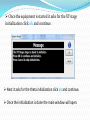
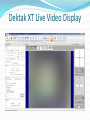
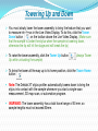
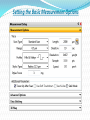
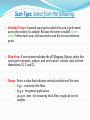
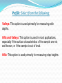
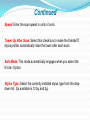
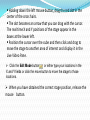
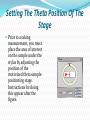
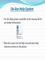
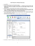
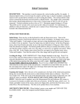
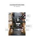
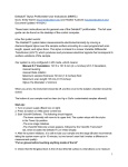
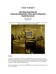
Dektak XT Surface Profiler System Overview The Dektak XT surface profiler is an advanced thin and thick film step height measurement tool. In addition to profiling surface topography and waviness, the Dektak XT system measures roughness in the nanometer range. The system can produce three-dimensional measurements and analyses when equipped with the 3D Mapping Option How to get started Release the EMO knob by rotating it clockwise until it pops up and turn on the white switch. Switch on the power supply. Double click on the Vision64 icon on the desktop. Once the equipment is started it asks for the XY stage initialization click ok and continue. Next it asks for the theta initialization click ok and continue. Once the initialization is done the main window will open. Continued As the software launches, the following event occurs: The tower assembly moves to its upper limit. The system stops with the stylus in the Tower Up position. The scan stage initializes. You can now safely position the sample beneath the stylus. The Vision64 Welcome screen appears, followed by the Vision64 Instrument tab. Allow the system to warm up for approximately 15 minutes before taking a scan measurement. Dektak XT Live Video Display Towering Up and Down You must slowly lower the tower assembly to bring the feature that you want to measure into focus in the Live Video Display. To do this, click the Tower Down button on the toolbar above the Live Video Display. (Make sure that the sample is under the stylus when the sample is towering down, otherwise the tip will hit the stage and will break the tip) To raise the tower assembly, click the Tower Up button. Up while unloading the sample) (always Tower To bring the tower all the way up to its home position, click the Tower Home button . Note: The Dektak XT stylus profiler automatically towers down to bring the stylus into contact with the sample whenever you start a single-scan measurement, 3D map scan, or automation program. WARNING: The tower assembly has a total travel range of 50 mm, so sample heights must not exceed 50mm. Setting the Basic Measurement Options Scan Type: Select from the following: Standard Scan: A normal scan type in which the scan is performed across the surface of a sample. Because the tower is nulled (tower down) before each scan, each successive scan has its own reference point. Map Scan: If your system includes the 3D Mapping Option, select this scan type to measure, analyze, and view surface contour data in three dimensions (X, Y, and Z). Range: Enter a value that indicates vertical resolution of the scan. 6.5 µ - extremely thin films. 65.5 µ - for general applications. 524 µ to 1 mm - for measuring thick films, rough and curved samples. Profile: Select from the following: Valleys: This option is used primarily for measuring etch depths. Hills and Valleys: This option is used in most applications, especially if the surface characteristics of the sample are not well known, or if the sample is out of level. Hills: This option is used primarily for measuring step heights. Continued Stylus Force: Enter a value between 1 mg and 15 mg. Length: Enter a scan length between 50 um and 55,000 um (55 mm). Duration: Enter amount of time it will take to complete a given scan. Scan duration, in conjunction with scan length, determines the horizontal resolution of a scan. For most applications, a 10 - 20 second scan provides adequate resolution and throughput. Resolution: Enter the horizontal resolution for the scan length and scan duration. The scan resolution is expressed in um/sample, indicating the horizontal distance between data points. Continued Speed: Enter the scan speed in units of um/s. Tower Up After Scan: Select this check box to make the DektakXT stylus profiler automatically raise the tower after each scan. Safe Mode: This mode automatically engages when you select the N-Lite+ Option. Stylus Type: Select the currently installed stylus type from the dropdown list. (tip available is 12.5µ and 2µ) Setting the X-Y Position of the Stage The X-Y Control Panel is located to the right of the Live Video Display. Instructions for using it appear after the figure. Holding down the left mouse button, drag the red dot in the center of the cross hairs. The dot becomes an arrow that you can drag with the cursor. The real time X and Y positions of the stage appear in the boxes at the lower left. Position the cursor over the cube and then click and drag to move the stage to another area of interest and display it in the Live Video Pane. Click the Edit Mode button or either type your locations in the X and Y fields or click the move button to move the stage to those locations. When you have obtained the correct stage position, release the mouse button. Setting The Theta Position Of The Stage Prior to a taking measurement, you must place the area of interest on the sample under the stylus by adjusting the position of the motorized theta samplepositioning stage. Instructions for doing this appear after the figure. Continued Holding down the left mouse button, drag the red bar in the centre of the ring. The bar becomes an arrow that you can drag with the cursor. The real time theta position of the stage appears in the box below the ring. This position is graphically depicted by the moving red indicator on the yellow ring. When you have obtained the correct stage position, release the mouse button. How to do a single scan measurement: 1. Check whether the stylus tower is raised if not click the tower up button on the tool bar above the video display. 2. Place the sample in the centre of the stage positioning the sample under the stylus. 3. Use the manual or auto stage controls (X-Y and Theta positioning) to position the area of interest under the centre of the live video display. 4. Click the tower down button on the tool bar to focus on the area of interest. 5 Use the slider on the illumination bar at the bottom of the live video display, the area of focus should be clearly illuminated. Continued 6. Select the required options on the Measurement options tab of the measurement setup dialog box. Note: Default Vision recipe automatically loads itself every time you start Vision64. 7. Initiate the scan measurement by clicking the measurement button on the ribbon and then selecting measurement or single acquisition. 8. When the measurement begins the tower assembly lowers and stylus touches the surface of the substrate. Stylus and its shadow is seen as shown in the picture below. Continued 9. After the stylus tip contacts the sample surface, it begins to scan over the surface features. The Live Video Display shows a real-time image of the stylus along with a measurement trace of the surface in the Data Acquisition window to the right. 10. At the end of the measurement, end measurement messages appears and click ok to open the data analysis view which shows the scan profile. 11. At the end of the scan measurement, the tower and stylus automatically move back to their starting positions, and the system is immediately ready for the next scan measurement. Measured Output: After the scan measurement is complete, the Data Analysis Display appears The surface features encountered by the stylus are represented as a two-dimensional profile. To the right, the output display shows a list of the scan parameters along with any user-requested analytical results. Powering Down The System Click the exit button in the upper right hand corner when confirmed to exit the program click yes. Close the vision64 by clicking the vision64 application button on the task bar followed by a closed window. Press the black OFF button on the EMO Box this shuts off power to all system devices but the computer, monitor, power supply adapter, and 24 VDC control circuit in the EMO Box. Select Start > Shut Down from the Windows 7 Start menu, and then click Shut Down in the dialog box that appears. Turn off the monitor. On-line Help System On-line help system is available on the vision64 tab for any further information. Place the cursor over the help icon and select help contents as shown in the picture. Do’s and Don'ts Once switched on leave the equipment for 15min as warm up time for maximum stability. Always place the stylus in the tower home position when the system is not in use. Make sure the stylus is touching the surface of the substrate while tower down. Use N-Lite and Safe mode to ensure scratch free measurement of resists, polymers and soft metals. Continued Use the emergency off button only in case of an emergency. Do not use lubricants on the stage leadscrews. Always position the sample so that the stylus is the only part of the stylus assembly that touches the sample. Keep the environmental enclosure door closed both when the DektakXT system is in use and when it is not. Continued Never connect or disconnect any cables when the power is on. Do not lower the tower without the stage assembly in place. Do not move a sample during a scan measurement. Avoid vibration and shock during measurements. For example, ensure that an operator does not bump a surface close to the profiler or the profiler itself during a measurement.