1
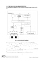
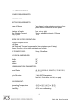
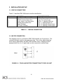
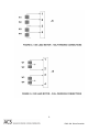
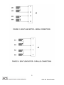
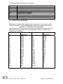
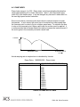
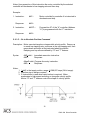
PRODUCT USER’S MANUAL
PMC-328
Programmable Stepping Motor
Driver/Controller
www.ACSMotion.com
Revision 1.0
1.
General Information 5
1.1
Warranty 5
1.2
Assistance and Maintenance Agreements 5
1.3
Documentation Discrepancies 6
1.4
Service Procedure 6
2.
PMC-328 DESCRIPTION 7
2.1
PMC-328 CONTROLLER FEATURES 7
2.2
PMC-328 BLOCK DIAGRAM DESCRIPTION 8
2.3
SPECIFICATIONS 9
3.
INSTALLATION SET-UP 10
3.1
PMC328 CONNECTORS 10
3.2
MOTOR CONNECTION 10
3.3
LIMIT, HOME, JOG, CURRENT OFF, PROGAM RUN INPUTS 13
3.4
COMMUNICATION SPEED 13
3.5
PMC-328 INPUT/OUTPUT LINES 13
3.6
FUSING 14
3.7
STEPPING MODE SELECT 14
3.8
MOTOR WINDING CURRENT ADJUSTMENT 14
3.9
TEST PUSHBUTTON, TEST LED 14
3.10
PMC328 DEFAULT PARAMETERS 15
4.
INSTRUCTION STRUCTURES 16
4.1
IMMEDIATE EXECUTION INSTRUCTIONS 16
4.2
PROGRAM LINE ENTER INSTRUCTIONS 17
4.3
PMC-328 COMMAND SUMMARY 18
4.4
ERROR RESPONSES 20
4.5
STEPPING RATE INDEXES 21
2
PMC-328 Driver/Controller
4.6
RAMP INDEX 22
5.
INSTRUCTION SET ALPHABETICAL ORDER 23
5.1
A = Address Set Command 23
5.2
B = Baud Rate Set Command 23
5.3
C = Constant Stepping Rate Index Set/Examine Command 24
5.4
CD – Count Decrement Command 25
5.5
CI – Count Increment Command 25
5.6
CO – Count Output Command 26
5.7
CT – Count Set/Examine Command 26
5.8
EL – Examine Program Line(s) Command 27
5.9
F – Finish (Soft Stop) Command 27
5.10
G – Go to Absolute Position Command 28
5.11
H – Seek Home Position Command 29
5.12
I – Index Number of Steps Command 30
5.13
J – Jog Rate Stepping Index Command 30
5.14
JH – Jump to Program Line on HI Port Line Command 31
5.15
JL – Jump to Program Line of LO Port Line Command 31
5.16
JP – Jump to Program Line Command 32
5.17
JZ – Jump on Zero Count Comand 32
5.18
K – Step Resolution Set/Examine Command 33
5.19
L – Limits Enable, Disable, Examine Command 33
5.20
LH – Examine Limits/Home Inputs Command 34
5.21
M+ - Move at Constant Stepping Rate Command 35
5.22
M – Motor Status Examine Command 35
5.23
NO – No Operation Command 36
5.24
OD – Output Data Command 36
5.25
OH – Output HI Level on I/O Port Line Command 37
5.26
OL – Output LO Level on I/O Port Line Command 37
5.27
P – Position Set or Examine
3
Command 38
PMC-328 Driver/Controller
5.28
PR – Program Run 38
5.29
PS – Program Stop 39
5.30
Q – Quit (Hard Stop) Command 39
5.31
R – Ramp Index Set or Examine Command 39
5.32
RS – Repeat Loop Set 40
5.33
RE – Repeat Loop End Command 41
5.34
SC – Subroutine Call Command 41
5.35
SR – Subroutine Return Command 42
5.36
T – Top Stepping Rate Index Set/Examine 42
5.37
V – Examine Controller Model and Version Command 43
5.38
W – Winding Current ON/OFF Control or Examine Command 43
5.39
WM – Wait for Motor to Stop Command 44
5.40
WH – Wait for HI Port Line Command 45
5.41
WL – Wait for LO Port Line Command 45
5.42
WT – Wait Specified Time Command 45
5.43
XL – Program Line Execute Command 46
5.44
Y – Set or Examine Motor Phase Current when Stepping Command 46
5.45
Z – Set or Examine Motor Phase Current When on Hold Command 47
6.
PROGRAMMING EXAMPLES 48
6.1
Single PMC-328 Controller; Example of repeat loop instruction. 48
6.2
Single PMC328 Controller; Example of subroutine call instruction. 48
7.
MANUAL REVISION HISTORY 49
4
PMC-328 Driver/Controller
1.
General Information
1.1
Warranty
ACS warrants its products to operate within specifications under normal use and
services for a period of one year from the date of shipment. Component
products, spares, replacement parts and repairs are warranted for 90 days.
Software is thoroughly tested and thought to be functional, but is supplied "as is"
with no warranty of any kind covering detailed performance. Accessory products
not manufactured by ACS are covered by the original equipment manufacturers
warranty only.
In exercising this warranty, ACS will repair or, at its option, replace, any product
returned to the customer service department or an authorized service facility
within the warranty period, provided that the warrantor's examination discloses
that the product is defective due to workmanship or materials and has not been
caused by misuse, neglect, accident, or abnormal conditions or operations.
The purchaser is responsible for the transportation and insurance charges arising
from the return of products to the servicing facility. ACS will return all in-warranty
products with transportation prepaid.
This warranty is in lieu of all other warranties, expressed or implied, including but
not limited to any implied warranty of merchantability, fitness, or adequacy for
any particular purpose or use. ACS shall not be liable for any special, incidental,
or consequential damages, whether in contract, or otherwise.
1.2
Assistance and Maintenance Agreements
Answers to questions concerning installation, calibration, and use of ACS
equipment are available from the customer service department, 35 Corporate
Park Drive, Pembroke, MA 02359, (781)829-9228.
ACS offers a selection of customer support services.
For example, maintenance agreements provide extended warranty and allow the
customer to budget maintenance costs after the initial one year warranty has
expired. Other services requested by the customer, such as installation, training,
on-site repair, and addition of engineering improvements, are made available
through specific Supplemental Support Agreements.
5
PMC-328 Driver/Controller
1.3
Documentation Discrepancies
ACS is committed to providing state-of-the-art products and is continually refining
and improving the performance of its products. While physical modifications can
be implemented quite rapidly, the corrected documentation frequently requires
more time to produce. Consequently, this manual may not agree in every detail
with the accompanying product. There may be small discrepancies in the values
of components and, occasionally, minor logic changes. Where any such
inconsistencies exist, please be assured that the unit is correct and incorporates
the most up-to-date circuitry.
1.4
Service Procedure
Products requiring maintenance should be returned to the customer service
department or authorized service facility. If under warranty, ACS will repair and
replace the part at no charge. The purchaser is only responsible for the
transportation charges arising from the return of the goods to the service facility.
For all ACS products in need of repair after the warranty period, the customer
must provide a Purchase Order Number before any inoperative equipment can
be repaired or replaced. The customer will be billed for the parts and labor for the
repair as well as for shipping.
6
PMC-328 Driver/Controller
2. PMC-328 DESCRIPTION
2.1 PMC-328 CONTROLLER FEATURES
This Advanced Control Systems Corp. programmable machine controller
contains control and power drive circuitry to operate any two or four phase
stepping motor with currents up to 3Amp per phase. It controls eight general
purpose input/output lines. There are also six dedicated control input lines. The
PMC-328 is powered by 115/230VAC. The control program can be entered into
the PMC-328’s non-volatile memory for autonomous operation, or it can be
controlled by a host computer. Several PMC-328 can be interconnected for a
larger system.
The stepping motor driver is two phase bi-polar type, which is highly efficient, and
results in cool operation of motors and drivers.
Motor winding run current is programmable in the range of .10 to
3.00Amps/phase. Hold winding current is also programmable in the range of 0 to
3.00Amps/phase.
Motors can operate in full step mode-two phases on, and ministep modes.
Ministep modes are 2, 3, 4, 5, 6, or 8 motor ministeps per full motor step.
Step mode is programmable.
The PMC-328 generates constant stepping rates as well as trapezoidal type
velocity profiles. Acceleration, deceleration and top speed are all programmable.
The dedicated control input lines are two limit inputs, home input, two jog inputs
and program “run” input.
All operational variables are retained in the EEPROM nonvolatile memory.
The PMC-328 understands high level instructions in the form of serial ASCII
messages. The instruction set covers all aspects of computer controlled motion
input/output, counter control, and is not dependent on the type of host computer
or operating systems.
Standard communication driver/receiver on board is a of RS-232C type. Other
types are optional.
7
PMC-328 Driver/Controller
2.2 PMC-328 BLOCK DIAGRAM DESCRIPTION
A functional block diagram of PMC-328 Motor Controller Board is shown in Fig.
2.1.
The imbedded control processor coordinates operation of the PMC-328
controller. It communicates via RS-232 communication interface with the host
computer. The programs (firmware) which interprets host instructions are stored
in flash memory. Operational variables, which can be changed, are stored in
non-volatile memory (EEPROM).
Also, up to 100 lines of motor and I/O control program can be stored in EEPROM
for autonomous operation of the PMC-328.
The processor generates stepping sequences to the power drivers.
8
PMC-328 Driver/Controller
2.3 SPECIFICATIONS
POWER REQUIREMENTS:
115/230VAC Max.
MOTOR REQUIREMENTS:
Type of Motors
Two phase bi-polar stepping motors or four
phase motors connected as two phase.
Number of Leads
Max Winding Current
Duty Cycle
Four, six or eight
3 Amp, adjustable down to .10Amp
100%
MODE OF MOTOR OPERATION:
BiPolar Chopper Drive
Full Step
Half Step with Torque Compensation (two ministeps per full step)
Three, four, five, six or eight ministeps per full step
AC POWER FUSE:
2Amp, Slow Blow
PHYSICAL DIMENSIONS:
Width:
Depth:
Height:
2.0”
3.8”
8.8”
COMMUNICATION PARAMETERS:
Baud Rates:
4.8, 9.6, l9.2, 28.8, 38.4, 57.6, 76.8, 115.2,
230.4 KBaud
Byte Structure:
10 bit ASCII characters:
Start bit, 8 data bits, stop bit; no parity
ENVIRONMENT:
Operating Temperature:
Storage Temperature:
Humidity:
-20°C to 50°C (-4°F to 140°F)
-20°C to 70°C (-4°F to 160°F)
<95% non-condensing
9
PMC-328 Driver/Controller
3. INSTALLATION SET-UP
3.1 PMC328 CONNECTORS
Table 3.1 identifies PMC-328 board controller identification.
DESIGNATION
J1
J2
J3
J4
J5
J6
FUNCTION
Eight General Purpose I/O Lines
RS232 Communication Port
Limits, Home, Jog, Run Inputs
Internal Interconnect Port
Motor Windings
AC Power Connect
TABLE 3.1
CONNECTOR TYPE
16 Pin, .l” spacing, dual row
6 Pin, RJ11 phone type
16 Pin, .1” spacing, dual row
6 Pin, .1” spacing dual row
4 Pin, .2” spacing, Phoenix type
3 Pin, .2” spacing, Phoenix type
PMC328 CONNECTORS
3.2 MOTOR CONNECTION
The stepping motor is connected to PMC-328 controller via J5 connector. The
connector accepts one four pin screw type plug. Two or four phase stepping
motor can be operated by the PMC-328 controller board. Stepping motors
equipped with four, six, or eight leads can be connected in several ways.
10
PMC-328 Driver/Controller
11
PMC-328 Driver/Controller
12
PMC-328 Driver/Controller
3.3 LIMIT, HOME, JOG, CURRENT OFF, PROGAM RUN INPUTS
The inputs are connected to PMC-328 via a 16 pin connector. Limit, and Home
inputs are normally closed. Jog and Current Off inputs are normally open.
Pulling “Program Run” input LO starts the program at program line 00..
PIN
15
13
11
9
7
5
3
1
INPUT
LIMIT
LIMIT –
HOME
JOG +
JOG –
PROGRAM RUN
NC
+5V
PIN
16
14
12
10
8
6
4
1
INPUT
GND
GND
GND
GND
GND
GND
GND
GND
TABLE 3.3 CONTROL INPUTS
3.4 COMMUNICATION SPEED
Communication Speed is programmable; see Instruction “B”. Available
communication baud rates are: 4.8 KBaud to 230.4 KBaud.
3.5 PMC-328 INPUT/OUTPUT LINES
There are eight I/O lines available for controllers I/O control each of the I/O lines
can be used as an input or output control. I/O lines direction are dynamically
configured under the program control. Connections to I/O lines are via 16 pin
connector J1.
PIN
15
13
11
9
7
5
3
1
INPUT
I/O line 1
I/O line 2
I/O line 3
I/O line 4
I/O line 5
I/O line 6
I/O line 7
I/O line 8
PIN
16
14
12
10
8
6
4
2
INPUT
GND
GND
GND
GND
GND
GND
GND
GND
TABLE 3.5 I/O LINES CONNECTION
13
PMC-328 Driver/Controller
3.6 FUSING
The PMC-328 programmable machine control has an on board fuse. The fuse is
to be rated accordingly to protect the motor; 2 Amp slow blow maximum.
3.7 STEPPING MODE SELECT
There are seven selections for stepping mode. Stepping mode is programmable
for full step or any of ministep modes. See instruction “K”.
MODES are:
FULL STEP, 2 PHASES ON
HALF STEP (TWO MINISTEPS/STEP)
THREE MINISTEPS/STEP
FOUR MINISTEPS/STEP
FIVE MINISTEPS/STEP
SIX MINISTEPS/STEP
EIGHT MINISTEPS/STEP
3.8 MOTOR WINDING CURRENT ADJUSTMENT
Motor Run Current and Motor Hold Current are programmable in .1Amp
increments in the range of 0 to 3.0Amp/Phase. See Instructions “Z” and “Y”.
3.9 TEST PUSHBUTTON, TEST LED
The Test Pushbutton has two functions:
1. When pushed momentary it will generate a test message:
#XV=PCM328-Vn. This message identifies the controller address, in
this case character “X”. It also identifies the controller model ID which
is PMC-328. It also identifies the firmware version number “Vn”, where
“n” is the version number.
When the message is properly displayed it also identifies the correct
communication setting.
2. When the pushbutton is pressed for a longer time, three seconds or
more, the controller will be preset with the default parameters.
14
PMC-328 Driver/Controller
The Test LED indicates several states of the PMC328 controller:
1. Blinking indicates the normal condition of the controller.
2. Steady OFF indicates no power or faulty state – program not running.
3. Steady ON indicates the stepper is running.
4. When the pushbutton is pressed in order to load the default
parameters, the LED will stay OFF until the default parameters are
reset for the controller. #XR↵ response message is generated at the
end of the procedure.
3.10 PMC328 DEFAULT PARAMETERS
Initially the PMC328 controller is preprogrammed with default parameters.
Through the use of the controller these parameters get changed into operational
parameters which are stored in the nonvolatile memory of the PMC328 controller.
After the controller
power-up, these operational parameters are retained. Default parameters can be
restored by pressing the test pushbutton for a longer time (5 sec.).
DEFAULT PARAMETERS ARE:
1. Top stepping rate index
T=24 (7200 steps/sec)
2. Constant stepping rate index
C=300 (576 steps/sec)
3. Jog stepping rate index
J=300 (576 steps/sec)
4. Ramp index
R=100 (6923 steps/sec/sec)
5. Baud rate index
N=1 (9.6 KBaud)
6. Limits index
L=1 (limits enabled)
7. Motor phase run current
Y=05 (0.5Amp/phase)
8. Motor phase hold current
Z=02(0.2Amp/phase)
9. Step resolution
K=2 (half step)
10. Individual address
X
11. Program memory lines 00 to 98 are preset with “NO” operation
instruction.
12. Program memory line 99 is preset with “JP00” instruction. i.e. jump to
program line 00.
13. Internal counter
CT=0
14. Position counter
P=0
15
PMC-328 Driver/Controller
4. INSTRUCTION STRUCTURES
4.1 IMMEDIATE EXECUTION INSTRUCTIONS
Immediate Execution Instructions are constructed from ASCII characters.
Alphabetic characters can be upper or lower case. Instructions are entered via
the controller’s serial communication port.
Instruction for immediate execution starts with the start character (#), controller
address (alphabetic character), data field (alphanumeric characters) and
terminator character (↵). Instructions are executed immediately.
Syntax:
Instruction:
#XCCddd↵
1.
2.
3.
#
X
CC
4.
5.
ddd
↵
Start Character (Hex 23).
Controller address character (A to Z, *).
One or two alphabetic command characters (upper or lower
case).
Data field (alphanumeric characters, +, -, =).
Terminator character (Hex OD).
Each immediate execution instruction with correct address generates a response
message from the controller.
Example:
#XI+2000↵
Controller X is instructed to step motor 2000 steps in a positive direction.
Instruction execution by the controller is confirmed with the response message:
Example:
#XR↵
X is the controller address
R is the execution confirmation character
↵ is the response terminator character
Example:
#XP↵
Controller is requested to respond with current motor position.
Response:
#XP=-500↵
16
PMC-328 Driver/Controller
4.2 PROGRAM LINE ENTER INSTRUCTIONS
Program Line Enter Instructions are constructed similarly to the Immediate
Execution Instructions but in addition have two numeric characters for the
program line number.
These instructions are executed under internal program controls.
Syntax
Instruction:
1.
2.
3.
4.
5.
6.
#XaaCCddd↵
#
X
aa
CC
ddd
↵
Example:
Start character.
Controller address character (A to Z, *)
Controller program line number (00-99).
One or two alphabetic command characters.
Data field (alphanumeric characters, +, -, =)
Termination character (Hex OD).
#X03I+2000↵
Instruction I+2000 is entered into the program line 03 for execution under
program control.
Response:
#XR↵
Wrong command or program instruction generates an error response.
Example:
#X5I2000↵…….Incorrect program line number must be two digit.
Response:
#XE3↵
Error number indicates type of error.
“*” The star character is an all address. Response messages are not generated.
No response by controller also indicates the wrong or non-existent controller
address.
17
PMC-328 Driver/Controller
4.3 PMC-328 COMMAND SUMMARY
Motion related commands:
M+
M-
Move number of steps at constant speed in positive direction using “C”
index.
Same in negative direction.
G+
G-
Go to absolute position using “T” and “R” indexes.
Negative direction.
I+
I-
Index number of steps using “T” and “R” indexes (Range +/-8,388,607
steps).
Negative direction.
H+
H-
Seek Home position, positive direction.
Negative direction.
F↵
Decelerate and stop motor (Soft Stop).
Q↵
Immediate stop of motor (Hard Stop).
M↵
Motor Status Examine (Stepping/Stopped).
Motion parameters Enter/Examine commands:
J=
J↵
Jog rage index set (Range 2 to 65535).
Examine jog rate.
C=
C↵
Constant rate index set (Range 2 to 65535).
Examine constant rate.
T=
T↵
Top rate (hi speed rate) set (Range 2 to 255).
Examine top rate index
R=
R↵
Ramp index set (Range 1 to 255).
Examine ramp index.
P=
P↵
Position set (Range +/-8,388,607).
Position examine.
18
PMC-328 Driver/Controller
Controller Set-up-Examine commands:
A=
Set address (Range A to Z).
B=
V↵
Set baud rate (Range 0 to 9).
Examine controller model and versions
Y=
Y↵
Set running motor phase current (Range 1 to 30).
Examine phase current
Z=
Z↵
Set holding motor phase current (Range 0 to 30).
Examine holding current.
K=
K↵
Set step resolution (Range 1 to 6, and 8).
Examine step resolution.
W=
W↵
Set winding current (ON/OFF).
Examine winding current status.
LE↵
LD↵
L↵
Enable limits
Disable limits
Examine limits status
LH
Examine limits/home inputs
Input/Output and counter commands:
OD
Output data
OH
Output HI level on output port line (port line 1 to 4).
OL
Output LO level on output port line (port line 1 to 4).
CT
Set counter contents (range 0 to 65535).
CI
Increment counter.
CD
Decrement counter.
CO
Output counter contents via serial port.
Program flow control commands:
JP
Jump to program line (range 00 to 99).
JH
Jump on HI on output port line (port line 1 to 8).
19
PMC-328 Driver/Controller
JL
Jump on LO on input port line (port line 1 to 8).
JZ
Jump on counter zero count.
WM
Wait for motor to stop.
WH
Wait for HI on input port line (port line 1 to 8).
WL
Wait for LO on input port line (port line 1 to 8).
WT
Wait specified time (range 0 to 65535 x 10mSec=0 to 655.35 Sec).
RS
Repeat loop set (range 00 to 99 repeats).
RE
Repeat loop end.
SC
Subroutine call.
SR
Subroutine return.
Program control commands:
XL
Program line execute.
NO
No operation.
EL
Examine program lines
PR
Program run
PS
Program stop
4.4 ERROR RESPONSES
An error response in form #XEn↵ is generated for various reasons. Instruction
itself is ignored.
1. Instruction structure following address #X is not recognizable or data is out
of range.
2. A motion instruction is executed while motor is already stepping.
3. A motion instruction is executed but motor current is shut off by W=0
instruction.
4. A motion instruction is executed but limit in that particular direction is
activated.
5. Quit or finish instruction is executed but motor is already stopped.
20
PMC-328 Driver/Controller
The following table describes error responses.
E1
E2
E3
E4
E5
E6
E7
E8
E9
Wrong instruction characters
Immediate execution not allowed
Not valid data
Motor is stopped
Wrong instruction structure
Program entry not allowed
Limits activated, motor is stepping, or motor current is off
Program line number not numeric
Motor is stepping
4.5 STEPPING RATE INDEXES
Stepping rate indexes define stepping rate for jog, move, index, and go motion
control instructions. Actual stepping rate in steps/sec is calculated by formula:
Step Rate = 172800/Rate Index (Steps/Sec)
Jog and move are constant rate instructions (no acceleration) and should be set
below start/stop rate of the motor load combination. Table 4.1 shows some
stepping rate calculations.
Step Rate Index
Step Rate
Step Rate Index
Step Rate
(Steps/Sec)
(Steps/Sec)
2880
60
86400
2
2160
80
57600
3
1728
100
43200
4
1152
150
34560
5
864
200
28800
6
691
250
24686
7
576
300
21600
8
432
400
19200
9
288
600
17280
10
216
800
15709
11
173
1000
14400
12
150
1152
13292
13
125
1382
12343
14
100
1728
11520
15
80
2160
10165
17
2880
60
20
8640
40
4320
6912
25
20
8640
5760
30
10
4937
17280
35
5
4320
34560
40
3
3456
57600
50
TABLE 4.1 STEP RATE TABLE
21
PMC-328 Driver/Controller
4.6 RAMP INDEX
Ramp Index range is 1 to 255. Ramp index controls acceleration/deceleration.
ramp while executing Go or Index instruction. Index 1 sets the slowest ramp,
index 255 is the fastest ramp. It can be changed any time and it takes effect on
the next high speed motion instruction.
Some motors have a resonant point where there is reduced torque at certain
frequencies. In such cases, the motor has to be started at a lower speed than
the resonant point in order to fly into a higher speed area. To minimize the time
to stay on the resonant point, higher ramp index for acc/dec must be applied. It
is recommended that a damper should be used to increase the inertia moment if
the motor goes in the resonant point with a small load.
TORQUE
STEPPING RATE
RESONANT POINT
Actual ramping rate in step/sec/sec is calculated by formula:
Ramp Rate = 1080000/(256 – Ramp Index)
RAMP INDEX
2
10
50
100
150
200
220
240
250
252
253
254
255
RAMP RATE (STEPS/SEC/SEC)
4252
4340
5243
6923
10188
19286
30000
67500
180000
270000
360000
540000
1080000
TABLE 4.2 RAMP RATE TABLE
22
PMC-328 Driver/Controller
5. INSTRUCTION SET ALPHABETICAL ORDER
5.1 A = Address Set Command
Description: Controller address is set to an alphabetical character. Default
address is character “X”.
Syntax:
#XA=Y↵
#XR↵
The default address “X” is changed to “Y”.
Controller responds with the old address.
New address is used on the following instruction.
Immediate execution instruction only.
Notes:
1. Address can be any of 26 alphabetic characters A to Z.
2. Address character is not case sensitive.
3. Star character (*) (Hex 2A) is an all controllers address. It cannot be
used as an individual controller address.
4. Address can be checked by pushing the test pushbutton. The
controller responds with outputting the controller version identification
message:
#YV=PMC328-Rn. “Y” is the controller address in this case, “n” is a
version number.
5.2 B = Baud Rate Set Command
Description: Controller communication rate is set. The default rate is 9.6 KBaud.
Syntax:
#XB=N↵
Immediate execution instruction.
No response is generated.
Following instructions are entered with the new baud
rate.
Notes:
1. New baud rate takes effect immediately.
2. Baud rates are set using baud rate numeric index N.
N = 0 = 4.8K
N = 1 = 9.6K
N = 2 = 14.4K
N = 3 = 19.2K
N = 4 = 28.8 K
N = 5 = 38.4K
N = 6 = 57.6K
N = 7 = 76.8K
N = 8 = 115.2K
N = 9 = 230.4K
Example:
Instruction:
#XB=6↵
Current baud rate of the controller with address X
is changed 23to 57.6K.
PMC-328 Driver/Controller
Response:
None
5.3 C = Constant Stepping Rate Index Set/Examine Command
Description: Constant stepping rate index can be set or examined. Constant
stepping rate index controls the stepping rate when M (Move) or H (Home)
motion is executed. The default value is 300, which is 576 steps/sec.
Syntax:
#XC=ddd↵
#XR↵
Immediate execution instruction setting of constant
stepping rate.
Response
#XaaC=ddd↵ Program line entry.
#XR↵
Response
#XC↵
#XC=ddd↵
Immediate examine of constant index rate
Response
Notes:
1. “ddd” is the step rate index; range 2 to 57599.
2. “aa” is the program line number; range 00 to 99.
3. Actual step rate in steps/sec is calculated by the formula:
Step Rate = 172800/rate index.
4. See Table 4.1 for some pre-calculated values.
Examples:
1. Instruction:
#XC=400↵
Response:
2. Instruction:
Response:
3. Instruction 3:
Response:
For controller “X” the step rate index is set to
400, which sets the motor step rate to 432
steps/sec.
#XR↵
#Y05C=1000↵ Controller “Y” program line 05 is
programmed with “C=1000” instruction.
#YR↵
#DC↵
Controller “D” is examined for constant rate
index.
#DC=17280↵ Controller “D” constant step rate index is set
to 17280 which use 10 steps/sec.
24
PMC-328 Driver/Controller
5.4 CD – Count Decrement Command
Description: Controllers internal counter is decremented for one count.
Syntax:
Notes:
#XCD↵
#XR↵
Immediate execution instruction; count is
decremented.
Confirmation response.
#XaaCD↵
#XR↵
Program line entry; decrement count.
Confirmation response.
1. Counter range is 0 to 65535 counts.
1. Counter decrements to 0; No underflow.
Examples:
1. Instruction:
Response:
2. Instruction:
Response:
#XCD↵
Controller “X: interval counter is decremented
one count.
#XR↵
#Y12CD↵
Controller “Y” program line 12 is programmed
with “CD” instruction.
#YR↵
5.5 CI – Count Increment Command
Description: Controller internal counter is incremented for one count.
Syntax:
#XCI↵
#XR↵
Immediate execution instruction count is incremented.
Confirmation response.
#XaaCI↵
#XR↵
Program line entry to increment count.
Confirmation response.
Notes:
1. Counter range is 0 to 65535
2. Counter overflows max. value to 0 and then stops. Increments
to 65535, no overflow.
Examples:
1. Instruction:
Response:
#FC1↵
Controller “F” internal counter is incremented
for one count.
#FR↵
25
PMC-328 Driver/Controller
2. Instruction:
#F40CI↵
Controller “F” program line 40 is programmed
with “CI” instruction.
5.6 CO – Count Output Command
Description: Contents of the internal counter is outputted via serial port.
Syntax:
#XCO↵
#XC=nnn↵
Immediate execution instruction
Response message
#XaaCO↵
#XR↵
Program line entry
Confirmation response
5.7 CT – Count Set/Examine Command
Description: Controller internal counter can be set or examined.
Syntax:
#XCT=ddd↵ Immediate execution counter set.
#XR↵
Confirmation message
#XCT↵
Immediate examine counter contents.
#XCT=ddd↵ Response, counter contents is outputted.
#XaaCT=ddd↵ Program line entry, counter set to ddd.
#XR↵
Confirmation message.
Notes:
1. Counter range is 0 to 65535 counts.
2. Only one counter is supported.
Examples:
1. Instruction:
Response:
#ZCT=100↵ Controller “Z” counter is set to 100.
#ZR↵
2. Instruction:
Response:
#ZCT↵
#ZC=100↵
3, Instruction:
#Z19CT=2000↵ Controller “Z” program line 19 is set to
“CT=2000” instruction.
#ZR↵
Response:
Controller “Z” is examined for count.
26
PMC-328 Driver/Controller
5.8 EL – Examine Program Line(s) Command
Description: Internal Program line(s) is displayed via serial port.
Syntax:
#XELaa↵
Immediate execution instruction only; display program
line aa.
#XaaM+2000↵ Response – contents of program line aa is
displayed; In this case, there is an instruction to
move 2000 steps in the positive direction.
#XELaa,bb↵ Immediate execution display program lines aa to bb.
#Xaa(Instruction) ↵ Response, program lines aa to bb are
displayed.
#Xaa+1 (Instruction) ↵
#Xbb(Instruction) ↵
Note:
1. This is the program support instruction to facilitate program
writing.
Examples:
1. Instruction:
Response:
#XEL00↵
Controller “X” to display program line 00.
#X00WT100↵ Line programmed with instruction “WT100”.
2, Instruction:
#XEL00,05↵ Display lines 00 to 05
#X00WT100↵; Program lines 00 to 05 are displayed
#X01I+200↵;
#X02WM↵;
#X03I-200↵;
#X04WM↵;
#X05JP00↵;
5.9 F – Finish (Soft Stop) Command
Description: Motor ramps down and stops.
Syntax:
#XF↵
#XR↵
Immediate execution instruction.
Response
#XaaF↵
#XR↵
Program line entry instruction.
Response
27
PMC-328 Driver/Controller
Notes: Upon execution of this instruction the motor controlled by the selected
controller will decelerate to low stepping rate and then stop.
Example:
1. Instruction:
#AF↵
Response:
#AR↵
2. Instruction:
Response:
Motor controlled by controller A is instructed to
decelerate and stop.
#A07F↵
Program line 07 of the “A” controller (Address
“A”) is programmed with the “F” instruction.
#AR↵
5.10 G – Go to Absolute Position Command
Description: Motor execute triangular or trapezoidal velocity profile. Ramps up
to reach top stepping rate, continues at the top stepping rate, then
ramps down and stops at the instructed absolute position.
Ramping and top rate are defined by “R” and “T” indexes.
Syntax:
#XG+ddd↵
#XR↵
Immediate execution instruction.
Response
#XaaG+ddd↵ Program line entry instruction.
#XR↵
Response
Notes:
1. “+ddd” is the target position; range +8,388,607 steps (24 bit range).
2. Direction sign is always required.
3. G Instructions is used when rapid motion is required. Motor
accelerates to high speed executing or triangular velocity profile.
Motion “R” and “T” indexes control the shape of velocity profile.
28
PMC-328 Driver/Controller
Examples:
1. Instruction:
Response:
2. Instruction:
Response:
#AG-5550↵ Go to position -5550. Controller “A” calculates
number of steps required to go from current
position to position -5550 and execute
trapezoid velocity profile move.
#AR↵
#A22G+0↵
Program line 22 of the “A” controller is
programmed with “G + 0” instruction.
#AR↵
5.11 H – Seek Home Position Command
Description: Motor steps at constant stepping rate in the instructed direction until
it Finds the Home position, or hits the Limit switch. Finding the Home Position
the motor will stop. Upon hitting the Limit switch, the motor starts stepping in the
reverse direction, seeking the Home position.
Syntax:
#XH+↵
#XR↵
Immediate execution instruction.
Response
#XaaH+↵
#XR↵
Program line entry instruction
Response
Notes:
1. Home and Limit inputs are normally LO; when triggered the input goes
HI.
2. When Home position is not found, the motor can be stopped by “Q”
command only.
Examples:
1. Instruction:
Response:
2. Instruction:
Response:
#BH+↵
Motor “B” seeks Home position in positive
direction.
#BR↵
#C02H+↵
#CR↵
Controller “C” program line 02 is set with H+
instruction.
29
PMC-328 Driver/Controller
5.12 I – Index Number of Steps Command
Description: Motor executes the triangular or trapezoidal velocity profile. Ramps
down and stops, completing the instructed number of steps. Ramping and top
stepping rate are defined by “R” and “T” indexes.
Syntax:
#XI+ddd↵
#XR↵
Immediate execution instruction
Response
#XaaI+ddd↵ Program line entry instruction
#XR↵
Response
Notes:
1. “+ddd” data is the number of steps to be completed. Range is
+8,388,607 steps (24 bit range).
2. Direction sign is always required.
Examples:
1. Instruction:
Response:
2. Instruction:
Response:
#ZI-400↵
Motor “Z” is to index 400 steps in negative
direction.
#ZR↵
#Z10I-400↵ Program line 10 of “Z”, controller is
programmed with “I-400” instruction.
#ZR↵
5.13 J – Jog Rate Stepping Index Command
Description: Jog stepping rate index can be set or examined. Jog rate index
controls stepping rate of Jog motion. The two Jog control lines are used to start
Jog motion in positive or negative direction.
Syntax:
#XJ=ddd↵
#XR↵
Immediate execution instruction
Response
#XaaJ=ddd↵ Program line entry instruction
#XR↵
Response
#XJ↵
#XJ=ddd↵
Immediate execution instruction
Response 30
PMC-328 Driver/Controller
Notes:
1. Examine Jog rate program line entry in not supported.
2. “ddd” is Jog rate index, range 2 to 57599.
Examples:
1. Instruction:
Response:
#ZJ=1000↵ Jog Rate Index is set to 1000
#ZR↵
2. Instruction:
#Z05J=1000↵ Program Line 05 of the “Z” controller is set
with the “J=1000” instruction.
3. Instruction:
Response:
#ZJ↵
#ZJ=1000↵
Jog Rate Index of “Z” controller is examined.
5.14 JH – Jump to Program Line on HI Port Line Command
Description: This is the conditional program flow control instruction. Jump of the
internal program is executed only if the instruction meets the conditions; i.e. HI
level on the specified port line.
Syntax:
#XaaJHp,bb↵
#XR↵
Program line entry instruction only.
Confirmation response.
Notes: 1. “aa” is current program line; “bb” is program line to jump to, “p” is port
line evaluated.
2. Instruction dynamically configures port line as an input line.
Example:
#Y12JH8,22↵
Program will jump from line 12 to line 22 if port
line 8 is High; otherwise, the program will
continue sequentially (line 13 etc.).
5.15 JL – Jump to Program Line of LO Port Line Command
Description: This is the conditional program flow control instruction. Jump of the
internal program is executed only if the instruction condition is met. i.e. LO level
on the specified port line. “P” range is 1 to 8.
Syntax:
#XaaJLp,bb↵Program line entry instruction only.
#XR↵
Confirmation response
Notes:
1. “aa” is the current program 31
line; “bb” is the program line
PMC-328 Driver/Controller
to jump to; “p” is the port line evaluated.
2. Instruction dynamically configures port line as input line
Example:
1. Instruction:
Response:
#Y12JL8,22↵Program will jump from line 12 to line 22
if port line 8 is LOW; otherwise, it will
continue to execute sequentially (line
13).
#YR↵
.
5.16 JP – Jump to Program Line Command
Description: This is an absolute program flow control instruction. Execution of
the internal program is changed from sequential execution to a specified program
line.
Syntax:
#XaaJPbb↵ Program line entry instruction only.
#XR↵
Confirmation response.
Notes:
1. “aa” is current program line; “bb” is the program line to jump to.
2. “aa” and “bb” are in the range 00 to 99.
Example:
1. Instruction:
#X22JP00↵ Program line 22 of the “X” controller is
programmed with “JP00” instruction. Program
jumps back to start line 00.
Response: #XR↵
5.17 JZ – Jump on Zero Count Comand
Description: This is the conditional program flow control instruction. Jump of the
internal program is executed only on zero count of the internal count.
Syntax:
#XaaJZbb↵ Program line entry instruction only.
#XR↵
Confirmation response.
Notes:
1. “aa” is the current program line.
2. “bb” is the program line to jump to.
Example:
32
PMC-328 Driver/Controller
1. Instruction:
#Y12JZ25↵ Program will jump from line 12 to line 25 on
zero count of the internal counter. Otherwise,
it will continue sequentially (line 13 etc.)
5.18 K – Step Resolution Set/Examine Command
Description: Step resolutions are set of examined. Step defines number of
ministeps within one full step.
Syntax:
#XK=N↵
#XR↵
#XK↵
Notes:
Immediate execution instruction. Step resolution is
set to N ministeps per full step.
Confirmation response
#XK=N↵
Immediate execution instruction. Step resolution is
examined.
Step resolution is N ministeps per full step.
#XaaK=N↵
#XR↵
Program line entry instruction; set step resolution.
Confirmation response.
Ministep Resolutions are:
N=1
N=2
N=3
N=4
full step
half step
three ministeps
four ministeps
N = 5 five ministeps
N = 6 six ministeps
N = 8 eight ministeps
1. Instruction:
Response:
#AK=5↵
#AR↵
Set resolution to five ministeps per step
2. Instruction:
Response:
#AK↵
#AK=5↵
Examine step resolution
3. Instruction:
#A10K=5↵
Program line 10 of “A” controller is
programmed With “K=5” instruction.
Examples:
Response: #AR↵
5.19 L – Limits Enable, Disable, Examine Command
Description: Limit inputs are enabled or disabled or examined. When limit inputs
are enabled and activated the motor will stop.
Syntax:
#XLE↵
Immediate 33execution instruction. Enable limits.
PMC-328 Driver/Controller
#XLD↵
#XR↵
Disable limits.
Confirmation response.
#XL↵
#XLE↵
#XLD↵
Immediate execution instruction. Limit status is
examined.
Limits enabled.
Limits disabled.
#XaaLE↵
#XR↵
Program line entry, enable limits.
Confirmation response.
Note:
1. Limits are enabled by default.
Examples:
1. Instruction:
Response:
#ALE↵
#AR↵
Controller A limits are enabled
2. Instruction:
Response:
#AL↵
#ALE↵
Examine limits of the controller “A”.
3. Instruction:
#A02LD↵
Program line 02 of the “A” controller is set with
“L=0” Instruction.
#AR↵
.
Response:
5.20 LH – Examine Limits/Home Inputs Command
Description: Two limit inputs and home inputs are examined for HI or LO input
voltage level.
Syntax:
#XLH↵
Examine Limit/Home input level, immediate
instruction only.
#XLH=abc↵ Response limit status is displayed.
Note:
1.
a = positive limit input
b = negative limit input
c = home input
1 for HI, 0 for LO
1 for HI, 0 for LO
1 for HI, 0 for LO
Example;
1. Instruction
Response:
#ALH↵
Examine Limits/Home of “A” controller.
#ALH=010↵ Controller “A” positive limit input is LO,
negative limit input if HI, home input is LO.
34
PMC-328 Driver/Controller
5.21 M+ - Move at Constant Stepping Rate Command
Description: Motor steps in positive or negative direction for specified number of
steps. Stepping rate is defined by “C” stepping rate index. The stepping rate can
be changed at any time, even when motor is stepping. Change of the stepping
rate takes effect immediately - Real time speed control.
Syntax:
#XM+ddd↵
#XR↵
Immediate execution instruction
Response
#XaaM+ddd↵ Program line entry instruction.
#XR↵
Response
Notes:
1. “ddd” number of steps to move – data field. Range +8,388607
steps.
2. Stepping is executed at constant stepping rate, defined by “C”
index, which can be dynamically changed.
3. Stepping can be terminated by executing “Q” command or “F”
Command.
Example:
1. Instruction:
Response:
#XM+1↵
#XR↵
Execute one step in positive direction.
Confirmation response.
2. Instruction:
#X15M+1↵
Program line 15 in programmed with “M + 1”
instruction.
Confirmation response.
Response:
#XR↵
5.22 M – Motor Status Examine Command
Description: Motor status is examined for stepping of stopped.
Syntax:
#XM↵
#XM=0↵
Or
#XM=1↵
Immediate execution instruction only.
Motor is stopped response.
Motor is stepping response.
Note:
1. Program line entry is not supported.
2. This instruction can be executed at any time for real time information
about motor status.
35
PMC-328 Driver/Controller
5.23 NO – No Operation Command
Description: No operation instruction can be used for filling used program lines.
It can also be used in immediate execution mode to check for the correct
communication set-up.
Syntax:
#XNO↵
#XR↵
Immediate execution instruction.
Confirmation response.
#XaaNO↵
#XR↵
Program line entry instruction.
Confirmation response.
Notes:
1. Default value of program line is “NO” no operation instruction.
2. Default values are set by pressing the test pushbutton until test LED
turns steady ON, also response message #XR is outputted.
5.24 OD – Output Data Command
Description: Data (ASCII string of characters) is outputted via serial port at
current baud rate.
Syntax:
#XODabc123↵ Immediate Execution Instruction
#Xabc123↵
Confirmation response
#XaaODabc123↵
#XR↵
Program entry line entry instruction
Response output
Note:
1. Data is ASCII string of characters; max length is 7 characters.
Examples:
1. Instruction:
Response:
#ZODDONE! ↵
#ZDONE! ↵
Output “DONE!” message
2. Instruction:
#Z49ODDONE! ↵
Controller “Z” program line 49 is
programmed with “ODDONE!”
instruction.
Response:
#ZR↵
36
PMC-328 Driver/Controller
5.25 OH – Output HI Level on I/O Port Line Command
Description: Instruction controls a single I/O line. HI level is outputted.
Syntax:
#XOHp↵
#XR↵
Immediate execution instruction
Confirmation response
#XaaOHp↵ Program line entry instruction
#XR↵
Confirmation response.
Note:
1. “p” is port line 1 to 4.
2. Instruction dynamically configures port line for an output.
Examples:
1. Instruction:
Response:
2. Instruction:
Response:
#ZOH2↵
Controller “Z” is instructed to output HI level on
port line 2.
#ZR↵
#Z11OH2↵
Program line 11 of “Z” controller is
programmed with “OH2” instruction.
#ZR↵
5.26 OL – Output LO Level on I/O Port Line Command
Description: Instruction controls a single I/O line. LO level is outputted.
Syntax:
#XOLp↵
#XR↵
Immediate execution instruction.
Confirmation response
#XaaOLp↵
#XR↵
Program line entry instruction
Confirmation response
Notes: 1. “p” is port line 1 to 4.
2. Instruction dynamically configures port line for an output.
Examples:
1. Instruction:
Response:
#YOL4↵
#YR↵
Controller “Y” is instructed to output LO level on
port line 4.
.
37
PMC-328 Driver/Controller
2. Instruction:
#Y44OL4↵
Program line 44 of “Y” controller is
programmed with “OL4” instruction.
5.27 P – Position Set or Examine Command
Description: Instruction sets the position counter or examines position counter.
Syntax:
#XP=+ddd↵ Immediate execution instruction
#XR↵
Confirmation response
#XaaP=+ddd↵ Program line entry instruction.
#XR↵
Confirmation response
#XP↵
Immediate execution instruction
#XP=+ddd↵ Response position display
Notes:
1. “+ddd” range is 0 to +8,388,607.
2. Direction sign is required always.
3. Position can be examined any time, motor stopped or stepping.
Examples:
1. Instruction:
#AP=+0↵
Position counter of “A” controller is initialized
to 0.
Response: #AR↵
2. Instruction:
Response:
3. Instruction:
Response:
#A00P=+0↵ Program line 00 of the “A” controller is
programmed with “P=+0” instruction.
#AR↵
#AP↵
Current position is examined.
#AP=-555↵ Current position is outputted.
5.28 PR – Program Run
Description: Internal program run command.
Syntax:
#XPR↵
Immediate execution instruction only. No response.
38
PMC-328 Driver/Controller
5.29 PS – Program Stop
Description: Internal program stop command.
Syntax:
#XPS↵
Immediate execution only. No response
5.30 Q – Quit (Hard Stop) Command
Description: Motor stop immediately command.
Syntax:
#XQ↵
#XR↵
Immediate execution instruction
Response
#XaaQ↵
#XR↵
Program line entry instruction
Response
Notes:
1. Instruction works only when motor is stepping.
2. When motor is stopped an error response is generated.
Examples:
1. Instruction:
Response:
#YQ↵
#YR↵
Motor controlled by “Y”
Controller stops immediately
2. Instruction:
#Y12Q↵
Program line 12 or “Y” controller is
programmed with Q instruction.
Response:
#YR↵
5.31 R – Ramp Index Set or Examine Command
Description: Ramp index can be set or examined. Ramp index controls ramping
(acceleration and deceleration) when executing G (GO) or I (Index) or
F (Finish) motion is executed.
Syntax:#XR=ddd↵ Immediate setting of ramp index. Immediate
execution instruction
#XR↵
Response
#XaaR=ddd↵ Program line entry instruction
#XR↵
Response
39
PMC-328 Driver/Controller
#XR↵
#XR=ddd↵
Immediate examine of ramp index
Response
Notes:
1. “ddd” is ramp index data; range is 1 to 255.
2. See table 4.2 for calculated values for the acceleration/deceleration
with respect to the ramp index. The higher value of index results in
faster acceleration/deceleration of a motor.
3. Calculation of the ramp rate (acceleration constant):
Ramp rate = 1080000/(256-ramp index)
4. Default ramp index is 100.
Examples:
1. Instruction:
Response:
2. Instruction:
Response:
3. Instruction:
Response:
#AR=200↵
Controller “A” ramp index is set to 200 which is
19,286 steps/sec/sec.
#AR↵
#A05R=200↵ Program line 05 of the “A” controller is set
with “R=200” instruction.
#AR↵
#AR↵
#AR=200↵
Controller “A” ramp rate index is examined
5.32 RS – Repeat Loop Set
Description: Program flow control instruction. The instruction indicates a start of
repeat loop; program segment between start and end of repeat loop will be
repeated by specified times. Nested repeat loops are not supported.
Syntax:
#XaaRSnnn↵ Program line entry instruction only
#XR↵
Confirmation response
Notes:
1. “nnn” repeat loop count, range 1 to 255.
2. Immediate execution is not supported.
Example:
1. Instruction:
#Z10RS100↵ Program line 10 of “Z” controller is set with
“RS100” instruction.
40
PMC-328 Driver/Controller
Response:
#ZR↵
Program segment:
#X10RS100↵ Set loop count to 100
#X11M+50↵ Move 50 steps in positive direction.
#X12WM↵
Wait for motor to stop.
#X13WT100↵ Wait for 1 second.
#X14RE↵
Repeat loop end.
5.33 RE – Repeat Loop End Command
Description: Instruction sets end of repeat program segment. It is the program
flow Control instruction.
Syntax:
#XaaRE↵
#XR↵
Program line entry instruction only
Confirmation response
Notes:
1. Immediate execution is not supported
Example:
1. Instruction:
Response:
#Z13RE↵
Program line 13 of “Z” controller is set with
“RE” instruction
#ZR↵
5.34 SC – Subroutine Call Command
Description: Program flow control instruction. Subroutine is called.
Syntax:
#XaaSCbb↵ Program line entry instruction only
#XR↵
Confirmation response
Notes:
1. Immediate execution is not supported.
2. “bb” is a subroutine starting line.
Examples:
1. Instruction: #X10SC60↵
Program line 10 of “X” controller is set with
“SC60” instruction
Response: #XR↵
Program Segment:
#X9--------↵ On line 10 41subroutine starting on line 60 is called.
PMC-328 Driver/Controller
After execution of the subroutine which is decreasing
count and wait/sec, program continues on line 11.
#X10SC60↵
#X11I-100↵
#X12------↵
#X60DC↵
#X61WT100↵
#X62SR↵
#X63--------↵
5.35 SR – Subroutine Return Command
Description: Subroutine return instruction.
Syntax:
#XaaSR↵
#XR↵
Program line entry instruction only
Confirmation response
Note:
1. “aa” is the last line of the called subroutine.
Example:
1. Instruction:
Response:
#X62SR↵
Program line 62 of “X” controller is set with “SR
instruction.
#XR↵
5.36 T – Top Stepping Rate Index Set/Examine
Description: Top stepping rate can be set or examined. Top rate index controls
the top stepping rate when G (GO) or I (Index) motion is executed. Default value
is 24.
Syntax:
#XT=ddd↵
#XR↵
Immediate execution instruction; setting of the top
rate.
Response
#XaaT=ddd↵ Program line entry instruction
#XR↵
Response
Notes:
1. “ddd” is the top stepping rate index, the range is 2-255.
2. Actual stepping rate is calculated by formula:
42
PMC-328 Driver/Controller
Step Rate = 172800/Rate Index
3. See Table 4.1 for some pre-calculated values.
Examples:
1. Instruction:
Response:
2. Instruction:
Response:
3. Instruction:
Response:
#AT=50↵
Controller “A” top rate is set to 50 which is
3456 steps/sec
#AR↵
#A03T=50↵ Program line 03 of “A” controller is set with
“T=50” instruction
#AR↵
#AT↵
#AT=50↵
Controller “A” is examined for top rate
5.37 V – Examine Controller Model and Version Command
Description: Examine controller model and version instruction facilitates the
communication set-up of the controller.
Syntax:
#XV↵
Immediate execution instruction only
#XV=PMC328-Rn↵ Response message
Notes:
1. “n” is the Version number of the Model PMC-328 Controller.
2. The same response message is obtained by pushing the test
pushbutton of the controller PMC-328.
5.38 W – Winding Current ON/OFF Control or Examine Command
Description: Instruction operates ON/OFF switch of the motor winding current. It
also examines status (On or Off) of the motor current.
Syntax:
#XW=n↵
#XR↵
Immediate execution instruction
Confirmation response
#XaaW=n↵ Program line entry instruction
#XR↵
Confirmation response
#XW↵
#XW=n↵
Immediate execution instruction
Response message
Notes:
1. “n” is 1 for ON, 0 for OFF.
43
PMC-328 Driver/Controller
Examine:
1. Instruction:
Response:
2. Instruction:
Response:
3. Instruction:
Response:
#AW=0↵
Turn “OFF” motor winding current for the motor
controlled by “A” controller
#AR↵
#A40W=1↵ Program line 40 of the “A” controller is set with
“W=1” instruction
#AR↵
#AW↵
#AW=1↵
Motor current is examined
Current is ON
5.39 WM – Wait for Motor to Stop Command
Description: Instruction stops next program line execution until motor stops
stepping. Program flow control instruction.
Syntax:
#XaaWM↵
#XR↵
Program line entry instruction only
Confirmation response
Notes:
1. Immediate execution instruction is not supported.
Example:
1. Instruction:
Response:
#X10WM↵
Program line 10 of “X” controller is set with
“WM” instruction
#XR↵
Program Segment:
X09……..↵
Motor completes motion GO to position -5000, then
outputs HI level on port line 5
X10G-5000↵
X11WM↵
X12OH5↵
X13……….↵
44
PMC-328 Driver/Controller
5.40 WH – Wait for HI Port Line Command
Description: Program flow instruction. Instruction stops the next program line
execution until specified port line goes HI.
Syntax:
#XaaWHp↵ Program line entry instruction only.
#XR↵
Confirmation response
Notes:
1. Immediate execution instruction is not supported.
2. “p” is the port line identifier; range is 1 to 8.
Example:
1. Instruction:
Response:
#Y20WH2↵ Program line 20 of “Y” controller is set with
”WH2” instruction. Program execution will stop
on line 20, until it finds port line 2 to be HI.
#YR↵
5.41 WL – Wait for LO Port Line Command
Description: Program flow control instruction stops the next program line
execution until specified port line goes LO.
Syntax:
#XaaWLp↵ Program line entry instruction only
#XR↵
Confirmation response
Notes:
1. “p” is port line identifier; range 1 to 8.
Example:
1. Instruction:
#Y20WL1↵ Program line 20 of “Y” controller is set with
“WL1” instruction. Program execution will stop
on line 20 until it finds port line 1 to be LO.
5.42 WT – Wait Specified Time Command
Description: Program flow control instruction stops the next program line
execution for the specified time.
Syntax:
#XaaWTnn↵ Program
45line entry instruction only.
PMC-328 Driver/Controller
#XR↵
Confirmation response
Notes:
1. “nn” is the time specifying index in increments of 10mSec. Range
Example:
1. Instruction:
#A15WT100↵
Response:
#AR↵
Program line 15 of “A” controller is set
with the “WT100 instruction. Program
execution will pause on Line 15 for 1
Sec., and then continue on line 16.
5.43 XL – Program Line Execute Command
Description: Instruction starts execution of the specified program line.
Syntax:
#XXLaa↵
Immediate execution instruction only
Notes:
1. Response to XL command depends on the instruction of the specified
program line.
2. “aa” program line number to be executed. Range 00 to 99.
3. This instruction facilitates program debugging and testing.
5.44 Y – Set or Examine Motor Phase Current when Stepping Command
Description: Instruction sets the motor run phase current in increments of
100mA. Setting can be also examined.
Syntax:
#XY=nn↵
#XR↵
Immediate execution instruction
Confirmation response
#XaaY=nn↵ Program line entry instruction
#XR↵
Confirmation response
#XY↵
#XY=nn↵
Immediate execution instruction
Response message
Notes:
1. “nn” current index in 100mA increments; range 1 to 30 (100mA to
3.00Amp).
2. Two digits required.
46
PMC-328 Driver/Controller
Example:
1. Instruction:
Response:
#XY=28↵
#XR↵
2. Instruction:
#X02Y=14↵ Program line 02 of “X” controller is set with
“Y=14” instruction
#XR↵
#XY↵
Examine run current
#XY=14↵
Run current is 1.4 Amp.
Response:
3. Instruction:
Response:
Motor phase current is set to 2.8 Amp.
5.45 Z – Set or Examine Motor Phase Current When on Hold Command
Description: Instruction sets the motor hold phase current in increments of
100mA. Setting can be also examined.
Syntax:
#XZ=nn↵
#XR↵
Immediate execution instruction
Confirmation response
#XaaZ=nn↵ Program line entry instruction
#XR↵
Confirmation response
#XZ↵
#XZ=nn↵
Immediate execution instruction
Response message
Note:
1. “nn” current index in 100mA increments; range 00 to 30 (0 Amp to 3.0
Amp) two digits required.
Example:
1. Instruction:
Response:
#XZ=05↵
#XR↵
2. Instruction:
#X02Z=00↵ Program line 02 of “X” controller is set with
(“Z=00”) instruction.
#XR↵
#XZ↵
Examine hold current
#XZ=00↵
Hold current is 0Amp
Response:
3. Instruction:
Response:
Motor hold current is set to .5Amp
47
PMC-328 Driver/Controller
6. PROGRAMMING EXAMPLES
6.1 Single PMC-328 Controller; Example of repeat loop instruction.
#X00NO↵
#X01P=+0↵
#X02WT100↵
#X03RS5↵
#X04M+2000↵
#X05WM↵
#X06WT100↵
#X07RE↵
#X08G+0
#X09WM↵
#X10JP02↵
;No operation
;Initialize position counter to 0
;Wait for one second before restarting motor
;Set 5 repeats
;Move 2000 steps in positive direction
;Wait for motor to stop
;Wait for 1 Sec.
;Indicate end of repeat loop
;Go back to 0 position
;Wait for motor to stop
;Jump to program line 02
6.2 Single PMC328 Controller; Example of subroutine call instruction.
#X00WL1↵
#X01SC10↵
#X02WH1↵
#X03JP00↵
#X10I+4000↵
#X11WM↵
#X12WT100↵
#X13I-4000↵
#X14WM↵
#X15SR↵
;Wait for low level on port line 1
;Call subroutine starting at line 10
;Wait for high level on port line 1
;Return to start line
;Index 4000 steps in positive direction
;Wait for motor to stop
;Wait for 1 second
;Index 4000 steps in negative direction
;Wait for motor to stop
;Return from subroutine to line 02.
48
PMC-328 Driver/Controller
7. MANUAL REVISION HISTORY
PMC-328 User’s Manual Revision History
Revision
1.0
Date of
Issue
Section
All
Original Release Revised Formatting
49
PMC-328 Driver/Controller

![e-track User`s Manual [FW1.00]](http://vs1.manualzilla.com/store/data/005696177_1-79f2a7130a6208690505d356432cfe5f-150x150.png)