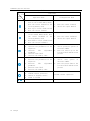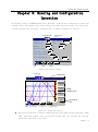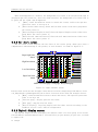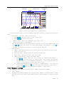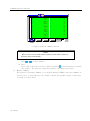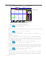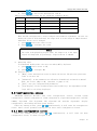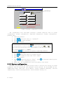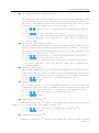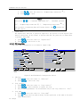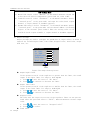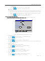
1
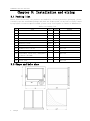
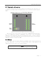
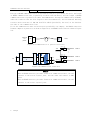
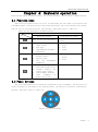
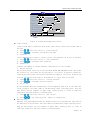
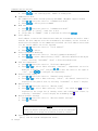
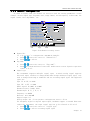
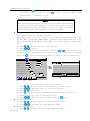
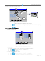
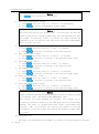
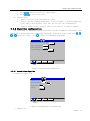
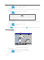
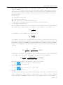
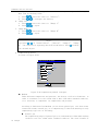
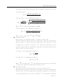
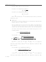
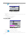
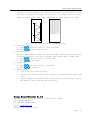
ZYW130-RG Chartless Recorder User's Manual SHAOXING ZHONGYI ELECTRONICS CO.,LTD. TABLE OF CONTENTS CHAPTER 1: INTRODUCTION ......................................... 1 CHAPTER 2: TECHNICAL SPECIFICATIONS ............................. 2 2.1 NUMBERS OF CHANNELS ...................................................................................................... 2 2.2 INPUT.................................................................................................................................. 2 2.3 OUTPUT .............................................................................................................................. 2 2.4 ACCURACY.......................................................................................................................... 2 2.5 RECORD INTERVALS ............................................................................................................. 2 2.6 RECORD CAPACITY .............................................................................................................. 2 2.7 RECORD TIME ...................................................................................................................... 2 2.8 SCREEN ............................................................................................................................... 3 2.9 POWER SUPPLY .................................................................................................................... 3 2.10 SIZE .................................................................................................................................. 3 2.11 NET WEIGHT ...................................................................................................................... 3 2.12 CONSERVATION CONDITIONS .............................................................................................. 3 2.13 WORKING CONDITIONS ...................................................................................................... 3 CHAPTER 3: INSTALLATION AND WIRING .............................. 4 3.1 PACKING LIST ...................................................................................................................... 4 3.2 SHAPE AND HOLE SIZE.......................................................................................................... 4 3.3 TERMINALS ALLOCATION ..................................................................................................... 5 3.4 WIRING ............................................................................................................................... 5 3.4.1 Power wiring ................................................................................................................ 6 3.4.2 Input signals wiring ...................................................................................................... 6 3.4.3 Output signals wiring ................................................................................................... 6 3.4.4 Thermocouple compensation wiring ............................................................................. 6 3.4.5 Communication printing wiring.................................................................................... 7 CHAPTER 4: KEYBOARD OPERATION ................................... 9 4.1 FUNCTION KEYS .................................................................................................................. 9 4.2 PANEL BUTTONS .................................................................................................................. 9 CHAPTER 5: RUNNING AND CONFIGURATION OPERATION .................. 11 5.1 MENU ............................................................................................................................... 12 5.1.1 Main menu ................................................................................................................. 12 5.1.2 Information sub-menu ................................................................................................ 12 5.1.3 Summary sub-menu ................................................................................................... 12 5.2 RUNNING SCREEN .............................................................................................................. 13 5.2.1 General view screen ................................................................................................... 13 5.2.2 Bar chart screen ......................................................................................................... 14 5.2.3 Digital display screen ................................................................................................. 14 5.2.4 Real time trend ........................................................................................................... 15 5.2.5 Information screen ..................................................................................................... 16 5.2.6 Historical trend .......................................................................................................... 18 5.2.7 Summary screen ......................................................................................................... 19 5.2.8 Adjust screen.............................................................................................................. 21 5.3 CONFIGURATION SCREEN ................................................................................................... 23 5.3.1 Main configuration screen .......................................................................................... 23 5.3.2 System configuration ................................................................................................. 24 5.3.3 Channel configuration ................................................................................................ 27 5.3.4 AO Channel Set ......................................................................................................... 30 5.3.5 PI sampling range setting ........................................................................................... 30 5.3.6 Resistor sampling range configuration ........................................................................ 30 5.3.7 Alarm configuration ................................................................................................... 31 5.3.8 Algorithm configuration ............................................................................................. 33 5.3.9 Display configuration ................................................................................................. 44 5.3.10 Data backup ............................................................................................................. 45 5.3.11 Data printting ........................................................................................................... 46 ZYW130-RG Chartless Recorder Chapter 1: Introduction Thank you for using ZYW130-RG Chartless Recorder. The manual provides users solutions of installation, operation, configuration, exception diagnosis, etc. To ensure the stable operation of ZYW130-RG Chartless Recorder, please read the manual carefully before installation and operation, and after that, please keep the manual properly. ZYW130-RG Chartless Recorder (ZYW130-RG) is a new product developed by Shaoxing Zhongyi Electronics Co.,Ltd. based on a number of key independent core technologies. Taking advantages of its solid technical basis and advanced awareness of science and technology, relying on years of instrumentation development and application experience, and on the basis of investigating the opinions of a wide range of new and old users in different industries, the performance and technical Specifications of the product is in a leading position of the same type of products in China. ZYW130-RG is a new intelligent recording instrument with an advanced 32-bit CPU, large-scale integrated circuit and graphic LCD display. The interface is information-rich, easy-to-operate and user-friendly: Fully isolated universal input, multiple signals input, without modules replacement, and software configuration is accessible. Use 32M large-capacity flash memory chip to store historical data, no data lost even power-off occurred. Standard serial communication interface: RS-232 and RS-485, Modbus RTU protocol. The clipboard copy and paste function can facilitate user parameter settings. The bit mark and unit of a project can be configured. Four groups of curves, free-form curves match, and the curve color can be customized. Equipped with standard USB interface, support USB1.1, USB2.0 disk, support FAT16/32, the historical data transmitting is simple. External micro-printer is supported to satisfy the requirement of field printing. ZhongYi 1 ZYW130-RG Chartless Recorder Chapter 2: Technical Specifications 2.1 Numbers of channels Maximally 16 channels are supported. 2.2 Input DDZ-II standard signal: 0~5V , 0~10mA DDZ-III standard signal: 1~5V , 4~20mA(Power distributable) Low voltage: 0~20mV, 0~100mV Thermal Resistance: Pt100, Cu50 Thermocouple: B, E, J, K, S, T Resistance signal: 0~400Ω Frequency: PI(0~30kHz,High level: 8.5~30V,Low level: 0~4.5V)(Please specify in order if needed) Digital input signal: DI Analog output signal: AO Isolation Impedance: 20MΩ @ 500V 2.3 Output Current: 4~20mA, Load capacity 750Ω (Maximally) Communication: RJ-11 communication interface,RS232/485 Protocol,Baud rate: 9600, 19200, 38400, 57600 Optional USB Interface: Multiple flash disks supported Alarm: Maximum 6 relay contacts, contact load: 0.5A@125VAC/1A@30VDC 2.4 Accuracy Real-time display: ±0.2% F.S.; Curve display: ±0.5% F.S.; Memory accuracy: ±0.2% F.S.; Common-mode rejection ratio :> 120 dB; Series mode rejection ratio :> 50 dB Note: thermocouple cold-error should be removed. 2.5 Record intervals 11 intervals from 1 to 240 sec.: 1/2/4/8/12/24/36/60/120/180/240sec. 2.6 Record capacity 64/128/192/248MB (FLASH capacity is optional). 2.7 Record time The record time of every channel is related to the flash memory capacity, number of input and the record interval of the channel, the formula is as follows: Flash _ capacity( MB) 1024 1024 Re cord _ int erval (sec.) Days of record (day ) Number _ of _ channels 16 24 3600 Example 1: Now we have an enhanced integrated instrument, only one channel is configured, the time interval is 60 seconds (select according to section 2.5), and the flash memory is 128MB, please calculate the record time according to these conditions and above formula: 2 ZhongYi ZYW130-RG Chartless Recorder 128( MB) 1024 1024 60(sec.) Days _ of _ record 5825(days) 116 24 3600 Example 2: Now we have an enhanced integrated instrument, eight channels are configured, the time interval of channel 1~4 are 24 seconds, and the time of channel 5~8 are 1second (According to section 2.5). The flash memory is 64MB; calculate the record time according to these conditions and above formula: 64( MB) 1024 1024 24(seconds) 145.6(days) 8 16 24 3600 64( MB) 1024 1024 1(seconds) Channel 5 ~ 8 :Days of record 6(days) 8 16 24 3600 Channel 1 ~ 4 :Days of record 2.8 Screen 5.6-inch true color TFT LCD, high brightness, CCFL backlight, and clear picture 2.9 Power supply New Switching Power Supply,85~265VAC,45~65HZ 2.10 Size Dimensions: 150mm 150mm 220mm 1 1 Hole size: 1380 mm 1380 mm 2.11 Net weight ≤2.5Kg 2.12 Conservation conditions Temperature: -20 to 60 ℃, avoid sunlight Humidity: <85% RH (non-condensing) 2.13 Working conditions Temperature: 0 to 45℃ Humidity: 10%~85% RH (non-condensing) ZhongYi 3 ZYW130-RG Chartless Recorder Chapter 3: Installation and wiring 3.1 Packing list Before leave the factory, the products are handled by collision prevention packaging, please carefully open the instrument package and check the items inside, if any lack or injury caused by negligence or serious impact founded, please notify local agents or contact us immediately. Table 3-1 Packing list No. Name Unit Amount Remark 1 ZYW130-RG Chartless Recorder Piece 1 2 Terminals Piece 1 3 Manual Piece 1 4 Installing bar (with M4 screw) Piece 2 5 Product certification Piece 1 6 Warranty cards Piece 1 7 Cold terminal compensator Piece 1 8 Communication cables Optional 9 Communications conversion module Optional 10 Instrument monitoring management software (CD-ROM) Optional 11 Micro Printer Optional 12 Flash disk Optional 3.2 Shape and hole size 4 ZhongYi The amount is up to model ZYW130-RG Chartless Recorder Figure 3.1 the shape and hole sizes of ZYW130-RG 3.3 Terminals allocation As shown in Figure 3.2: the signal terminals are divided by every four pieces, in accordance to one signal channel. The number before A, B, C, D stands for channel sequence number. Figure 3.2 the back side terminal allocation of ZYW130-RG There are two 6-core crystal sockets on the back side of ZYW130-RG Chartless Recorder, one is the communication interface of RS232/485, and the other is the cold terminal compensator of the thermocouple. When there are thermocouple signals, in order to eliminate the influence of environment temperature variation and ensure the accuracy, the cold terminal compensator should be inserted into COM2. 3.4 Wiring Power supply, input and output terminals use pluggable blocks, which facilitates the day-to-day maintenance on the basis of ensuring good contact. Cold-compensator and communications line use the six core crystal interface. Notice 2 The sectional area of the wire:0.5~2.5mm ,torque:50Nm。 ZhongYi 5 ZYW130-RG Chartless Recorder 3.4.1 Power wiring Figure 3.3 Power wiring 3.4.2 Input signals wiring A B C D A B C D + - + A 24V+ A - B C D Singal+ B C + D - Two-wire Transmitter Distribution Type II/III Standard Voltage Signal A A A B B B C D C D C D + Type II/III Standard Current Signal Thermal Resistence Common Terminal Three-wire Transmitter Distribution Impulse Signal A + B C + - D - Thermocouple Switch Signal Figure 3.4 Input signals wiring Notice The types of input signals still need to be configured by software. Please refer to section 5.3.3. 3.4.3 Output signals wiring A B C D K Alarming Contacts Output + Analog Output Figure 3.5 Output signals wiring 3.4.4 Thermocouple compensation wiring If thermocouple signal exists in the input signals, in order to take more accurately cold compensate to the thermocouple, together with the features of our company's products, we add some explains in the definition of thermocouple wiring as following, and the wiring picture is shown in Figure 3.6 1. Connect the thermocouple compensation wire to the attached two-core terminal adapter, and then use ordinary wire to connect the recorder terminals, the length of ordinary wire is 50 cm; 2. Extend 50 cm to the attached cold end compensator, and connect it to the cold end compensator port (COM2); 6 ZhongYi ZYW130-RG Chartless Recorder 3. Make the cold end compensator as close as possible to the two core terminal adapters; 4. Connect the cold end compensator and re-power, so that the cold end compensator can work. CO M2 CO M1 Ordinary wire, connect to the recorder Input terminal Two-core switch terminal Thermocouple compensate wire Cold end compensator Figure 3.6 Cold-end compensator wiring Notice After the cold-end compensator is connected, the instrument has to be re-powered. 3.4.5 Communication printing wiring True color chartless recorder provides RS232 or RS485 communication interface, they are all fetched out from the backside COM1 of the instrument, when communicates with PC, the interface definition is like figure 3.7 and table 3-2. COM1 6 1 Figure 3.7 Communication interface Table 3-2 the definitions of communication interfaces COM1 Pin Definition 1 RS232 receiving data RXD 2 RS232 sending data TXD 3 RS485 communicating 485-(B) 4 -- 5 RS232 signal ground GND ZhongYi 7 ZYW130-RG Chartless Recorder 6 RS485 communicating 485+(A) The type of RS485 communication wire is shielded twisted pair (provided by the user), the length of RS232 communication wire is generally not more than 10 meters, and the length of RS485 communication wire is generally not more than 1000 meters. During the communication of RS485, under the condition that the wire length is more than 100 meters, the end terminal matching resistor with resistance of 120 ohm should be added (provided by the user) at the farthest two ends of the communication line. If use the communication wire and accessories provided by our company, the RS232 connection between computer or printer is as shown in Figure 3.8, and RS485 connections are shown in Figure 3.9. Compute r or printer Six-core crystal joint DB9 Com 1 Figure 3.8 Communication or printer connection Sixcore Green Crystal Joint Instrument n Sixcore Crystal Joint Instrument 2 Com 1 Sixcore Green Crystal Joint Instrument 1 Com 1 White (n<64( Com 1 …… 120R White RS232/RS48 5 PC Gree n 120R TX- 485+(A) 485-(B) TX+ White Figure 3.9 Communication connection Notice When use RS232 function, provide 1.5 meters of communication wire, one end connects to the 6-core crystal joint, and the other end connect to DB9 joint. When use RS485 function, provide 1.5 meters of communication wire, one end connects to the 6-core crystal joint. 8 ZhongYi ZYW130-RG Chartless Recorder Chapter 4: Keyboard operation There are two types of operation keys, one is function keys, and the other is panel buttons. 4.1 Function keys There are four function keys in total, located under the left-down cover board of the instrument panel. Softly press the cover board and release, the cover board will be opened, and you can see the function keys. The specific functions refer to table 4-1 Table 4-1 the functions of function keys Function Description Symbol Operating status Configuration status Open and run the main menu Exit the configuration screen 1. 2. 3. 1. 2. 3. 1. 2. 3. 4. shortcut to the bar chart screen next page switch manual/automatic adjustment shortcut to the digital display screen previous page save the adjustment parameters shortcut to the real-time trend screen looping display the curves group screen switch memory methods erase alarming or power-off record 1. 2. 3. Copy Save Print 1. 2. Paste Stop 4.2 Panel buttons The five panel buttons are located the right-down of the instrument; the allocation is shown in figure 4.1. According to the running status, the function of each key is different. Specific functions refer to table 4-2 Figure 4.1 panel keyboard ZhongYi 9 ZYW130-RG Chartless Recorder Table 4-2 the functions of panel buttons Descript ion Sym-b olls Functions Operation mode 1. 2. 3. 1. 2. 3. 1. 2. 3. 4. 5. 1. 2. 3. 4. 5. 1. 2. 3. 4. + 10 ZhongYi check the previous historical data in the normal memory mode; move the cursor forward in the locating memory mode move up to choose alarm record move the cursor forward check the next historical data in the normal memory mode; move the cursor backward in the locating memory mode move down to choose alarm record move the cursor backward switch channels upward increase the parameters of the adjustors increase PID adjustment parameter increase time label increase the memory time switch channels downward decrease the parameters of the adjustors decrease PID adjustment parameter decrease time label decrease the memory time open and run the main menu screen affirm current operation vanish or display curves alarm to affirm Switch to the configuration mode Configuration mode 1. 2. move the cursor forward switch the input method 1. 2. move the cursor backward switch the input method 1. choose previous option or increase number move the cursor up in the location label modification picture 2. 1. 2. choose next option or decrease number move the cursor down in the location label modification picture affirm current operation ZYW130-RG Chartless Recorder Chapter 5: Running and Configuration Operation The display screen of ZYW130-RG Chartless Recorder is mainly the configuration screen and running screen. The display area of the screen is divided into three parts: the status bar, the main display area (setting), operation bar, as shown in Figure 5.1 and 5.2. Sound On/Off Channel Set Alarm sign 2007-07-27 09:18:30 Channel No.: 02 Tag name: Singal type: 0-5V Unit: V Range L: 0.0 H: 100.0 Record capacity: 31 M Filtering time: 00 S Low signal cut-off: 0.0 % Zero adjustment: K: 1.00 B: exit copy CHN02 0.0 stick Figure 5.1 Setting screen Loop sign Status bar Real-time trend 2007-07-13 09:18:30 1 min/div 90 Channel01 √ 80 01 86.2 m3/h 70 Channel02 60 √ 50 02 40 30 62.0 m3/h Channel03 √ 03 Main display area 37.5 m3/h 20 Channel04 10 √ 04 << Menu Previous page >> Next page 13.6 m3/h Operation bar Looping display Figure 5.2 operation screen The unified status bar is used for displaying the screen name, button sound sign, alarm sign, recycling display sign and current system time, all records and internal operations are based on the time. ZhongYi 11 ZYW130-RG Chartless Recorder The setting screen is used for setting the instrument in accordance with different display; the main display area is used for monitoring and observation by digital chart, bar chart, curve chart according to different display. If alarm happened in the channel, the alarm sign displayed on the status bar, after the alarm cancelled, the sign disappear. 5.1 Menu 5.1.1 Main menu Under any running screens, move the cursor to [menu] and press button or [F1] button, the main menu will be displayed in the center of the screen, as shown in Figure 5.3 Overview Bar Digital Disp Real-time Information History Accumulation Control Figure 5.3 menu bar 1. press , or , to move cursor to different buttons in the menu bar 2. press to enter corresponding running screen 5.1.2 Information sub-menu Under the main menu, move cursor to Information Screen, and press to enter the information sub-menu. Alarm Record Power-off rec. Exit Figure 5.4 Information sub-menu 1. Information sub-menu selection 1. press , or , to move the cursor to “alarm record” or “power-off record”; 2. press to affirm, the instrument will enter corresponding screen 2. Exit option 1. press , or , to move the cursor to “Exit”; 2. Press to affirm, the instrument will exit the sub-menu. 5.1.3 Summary sub-menu Under the main menu, move the cursor to the “summary screen”, press information sub-menu. 12 ZhongYi to enter ZYW130-RG Chartless Recorder Daily Monthly Exit Figure 5.5 Summary sub-menu 1. Summary sub-menu selections 1. press , or , to move the cursor to “Daily summary” or “Monthly summary”; 2. press to affirm, the instrument will enter corresponding screen 2. Exit 1. press , or , to move the cursor to “Exit” 2. Press to affirm, the instrument will exit the summary screen. 5.2 Running screen ZYW130-RG Chartless Recorder has seven basic running screens and three optional running screens. The seven basic running screens are general view screen, bar chart screen, digital display screen, real time trend, information screen (alarm records, power-off records), historical trend screen. If the instrument opened the “summary calculation” and “PID” method, then there will be additional daily summary, monthly summary and adjustment screen. 5.2.1 General view screen General view screen can display all the measuring points in the same screen, as shown figure 5.6. Sound on/off General view 01 3 m /h 90.0 Channel01 05 m3/h 420.0 Channel05 Alarm sign 2007-07-13 09:18:30 02 3 m /h 287.0 Channel02 06 m3/h 900.0 Channel06 03 m3/h HI 387.0 Channel03 07 m3/h 252.8 Channel07 04 m3/h 500.0 Channel04 08 m3/h -19.9 Channel08 Menu Enter digital chart Enter the trend chart Enter the bar chart Figure 5.6 VPR130-RG eight channels general view The information displayed in the general view includes date, time, sound on/off sign, alarm sign, etc. The information for each channel includes channel No. project unit, project capacity ZhongYi 13 ZYW130-RG Chartless Recorder and location label. When alarm happened in a channel, the background color turns to be red and alarm sign is displayed upon the status bar, after the alarm canceled, the background color turns back to be green and the alarm sign disappeared. 1. [Menu]: enter the menu-bar screen to switch the screen, and for the specific operations refer to section 4.2 2. [Enter the bar chart screen]: Enter the bar chart screen of the curve group where the cursor points to 3. [Enter the digital display screen]: Enter the digital display screen of the curve group where the cursor points to 4. [Enter the real time trend screen]: Enter the real time trend screen of the curve group where the cursor points to 5.2.2 Bar chart screen The bar chart screen displays the bar chart of two curves group, which gave users a comprehensive understanding of the quality of each channel, as shown in figure 5.7: Bar chart screen Super high limit alarm 2007-07-27 09:18:30 Group 1 Group 2 % 90 01 80 High limit alarm 02 70 60 03 50 04 40 Low limit alarm 05 30 06 20 Super low limit alarm 10 07 00 08 << 25.0 m3/h 14.8 m3/h 46.1 m3/h 55.6 m3/h 67.5 m3/h 57.0 m3/h 43.2 m3/h 34.6 m3/h >> Menu Previous page Next page Recycle display Figure 5.7 eight channels screen The bar chart screen has the triangle cursor which is used for displaying alarm limits, users can judge whether alarm happened by the relative locations of bar chart and triangle cursors. 1. [Menu]: enter the menu-bar screen to switch the screen,. The specific operations refer to section 4.2 2. [Previous page]: display previous bar chart; 3. [Next page]: display next bar chart; 4. [Recycle display]: recycling display each bar chart screens according to the automatic recycle circle switch configuration 5.2.3 Digital display screen The digital display screen can display the channel values of a curve group in one screen; the information includes Channel Label, location label, project amount, project unit, as shown in figure 5.8: 14 ZhongYi ZYW130-RG Chartless Recorder Digital display 2007-07-13 09:18:30 Channel01 01 02 Channel02 500.8 550.2 m3/h m3/h Channel03 03 04 Channel04 27.8 -1.9 m3/h << m3/h LL >> MenuPrevious page Next page Recycling display 1. 2. 3. 4. Figure 5.8 the digital display screen of one curves group channels [Menu]: enter the menu-bar screen to switch the screen. The specific operations refer to section 4.2 [Previous page]: display previous digital chart; [Next page]: display next digital chart; [Recycle display]: recycling display each digital chart screen according to the automatic recycle circle switch configuration 5.2.4 Real time trend The content in real time trend screen is mainly the curves of a curve group channel. The information includes date, time, time label, location number, project amount, Channel number, project unit, curve display sign, etc. as shown in figure 5.9: Time label Real time trend 2007-07-13 09:18:30 1 min/div Display sign 90 通道05 √ 80 01 86.2 m3/h 70 通道06 60 √ 50 02 40 30 62.0 m3/h 通道07 √ 03 Channel number Cursor Location number 37.5 m3/h Project amount 13.6 m3/h Project unit 20 通道08 10 √ 04 << >> Menu Previous page Next pageRecycling display Figure 5.9 Real Time Trend Screen ZhongYi 15 ZYW130-RG Chartless Recorder 1. “Time label”: the time length of each grid 1. press or to move the cursor to the “Time label”; 2. Press or to select time label. 2. The display of curves One screen of real-time trend can display the curve and data of maximum four channels . When user needs to check one or more channels more clearly, they can use appearance configuration to configure. Specific operation: 1. press or to move the cursor to the “display sign” of the channel to be configured; 2. press to select:”√”: display,”×”: No display. 3. Function keys 1. [menu]: enter the menu-bar screen to switch the screen. The specific operations refer to section 4.2 2. [previous page]: display previous real-time trend chart; 3. [next page]: display next real time trend chart; 4. [recycle display]: recycling display each digital chart screens according to the automatic recycle circle switch configuration 5.2.5 Information screen Information screen includes two parts: alarming record, power-off record. 5.2.5.1 Alarming record As shown in figure 5.10, the alarming record screen can display 8 latest records of date, time and type for all the channels or single one, totally 24 alarming records can be saved, and displayed by three screens. In which there are four types: HH: Extra high alarm HI: high alarm LO: low alarm LL: Extra low alarm Alarming record No. 01 02 03 04 05 06 07 08 Alarm Time 07 – 07 - 11 07-07-11 11:01:10 11 : 01 : 10 07 – 07 - 11 07-07-11 11:01:10 11 : 10 : 10 07 – 07 - 11 07-07-11 11:01:10 11 : 01 : 10 07 – 07 - 11 07-07-11 11:01:10 11 : 10 : 10 07 – 07 - 11 07-07-11 11:01:10 11 : 01 : 10 07 – 07 - 11 07-07-11 11:01:10 11 : 10 : 10 07 – 07 - 11 07-07-11 11:01:10 11 : 01 : 10 07 – 07 - 11 07-07-11 11:01:10 11 : 10 : 10 << Menu Previous page 2007-07-13 09:18:30 Canceled time Channel 07 – 07 - 11 07-07-11 11:02: 11 : 02 : 10 07 – 07 - 11 07-07-11 11:02: 11 : 13 : 10 07 – 07 - 11 07-07-11 11:02: 11 : 02 : 10 07 – 07 - 11 07-07-11 11:02: 11 : 13 : 10 07 – 07 - 11 07-07-11 11:02: 11 : 02 : 10 07 – 07 - 11 07-07-11 11:02: 11 : 13 : 10 07 – 07 - 11 07-07-11 11:02: 11 : 02 : 10 07 – 07 - 11 07-07-11 11:02: 11 : 13 : 10 02 LO x 01 LL x 02 LO √ 05 LL x 03 HH √ 05 LL √ 02 LO x 05 LL √ >> Type Channel: All Next page Erase alarm record Figure 5.10 Alarm Record Screen 16 ZhongYi Confirm ZYW130-RG Chartless Recorder 1. Channel Press or to select Channel Label or “all”; 2. Select alarm 1. In the “confirm queue”press to move up the selected alarm record; 2. In the “confirm queue” press to move down the selected alarm record; 3. press to confirm the record 3. Function keys 1. [Menu]: enter the menu-bar screen to switch the screen. The specific operations refer to section 4.2 2. [Previous page]: display previous eight records; 3. [Next page]: display next eight records; 4. [Erase alarm records]: enter the password as shown in figure 5.11. The operation of erasing records is as following: a) press or to move the cursor to the input space and input password; b) after entered correct password, press to confirm, the password sign turns from” “to” “; c) press or to move the cursor to[Exit], press to return the alarm records screen; d) in the alarm records screen press or[F4]to erase the alarming records; Enter the password 00 00 00 Exit Figure 5.11 Password Input Dialogue 5.2.5.2 Power-fail record As shown in figure 5.12, the power-fail screen can display eight power-fail records, totally 24 records can be saved. Power-off record 2007-07-13 09:18:30 No. Power-off time Recover time 01 07-07-11 11:01:10 07-07-11 11:02: 15 02 07-07-11 12:01:10 07-07-11 12:02: 15 03 07-07-12 11:01:10 07-07-12 11:02: 15 04 07-07-12 21:01:10 07-07-12 21:02: 15 05 07-07-22 11:01:10 07-07-22 11:02: 15 06 07-07-23 11:01:35 07-07-23 11:02: 15 07 07-08-11 01:01:20 07-08-11 05:02: 15 08 << >> MenuPrevious page Next page Erase power-off record ZhongYi 17 ZYW130-RG Chartless Recorder 1. 2. 3. 4. Figure 5.12 power-off record screen [Menu]: enter the menu-bar screen to switch the screen. The specific operations refer to section 4.2 [Previous page]: display previous eight records; [Next page]: display next eight records; [Erase power-off records]: enter the password input dialogue, The operation of erasing records is the same as “Erase alarm records” 5.2.6 Historical trend The historical trend screen can observe, analyze and compare the recorded historical data of all channels. The memory screen can display the history curves for four channels of a curve group, as shown in figure 5.13, 5.14. Fixed point Memory time Time label History trend 2007-07-13 09:18:30 2007-07-13 05:18:30 1 min/div 90 通道01 √ 80 01 70 通道02 60 √ 50 02 40 30 86.2 m3/h 62.0 m3/h 通道03 √ 03 37.5 m3/h 20 通道04 10 √ 04 << 13.6 m3/h >> Menu Previous page Next page Fixed point memory Figure 5.13 History trend screen: fixed point memory 18 ZhongYi ZYW130-RG Chartless Recorder Fixed point confirm Memory time Time label History trend 2007-07-13 09:18:30 2007-07-13 05:18:30 1 min/div 90 CHN01 √ 80 01 86.2 m3/h 70 CHN02 60 √ 50 02 40 30 62.0 m3/h CHN03 √ 03 37.5 m3/h 20 CHN04 10 √ 04 << 13.6 m3/h >> Menu Previous page Next page Common memory Figure 5.14 History trend screen: common memory In history trend screen, you can only modify time label, whether to display in fixed point mode. “Time label”: the time length of each grid 1. press or to move the cursor to the “Time label”; 2. Press or to select time label. 1. “Memory time”: means the rightmost time of the curve 2. “Fixed point memory confirmation” When the memory mode is fixed point memory, the user has set up the memory time, and press or to move the cursor to”fixed point memory confirmation”, press to confirm, the screen will display a curve before the time set 3. Function keys 1. [Menu]: enter the menu-bar screen to switch the screen. The specific operations refer to section 4.2 2. [Previous page]: display previous real-time trend chart; 3. [Next page]: display next real time trend chart; 4. [Memory mode switch]: switch the memory mode: a) Fixed point memory: When the icon of [F4] is “Fixed point memory” , press or to move the cursor to “memory time” and set time. The specific operation refers to”fixed memory confirmation”; curve disappear operation refers to the operation of Real time trend screen; b) [Common memory]: When the icon of [F4] is “Common memory”,the cursor can not be moved. Single click , the curve will move forward a “time label”; single click , the curve will move backward a “time label” 5.2.7 Summary screen The summary screen include two parts: daily summary and monthly summary 1. daily summary The function of daily summary is to display daily summary of current month, so that the user can clearly control the produce status of current month, as shown in figure 5.15: ZhongYi 19 ZYW130-RG Chartless Recorder Daily Summary July 12th Summary 01: 02: 03: 04: 05: 06: 07: 08 : 09: 10: 11: 12: 13: 14: 15: 16: 2007-12-16 16:18:30 122398.0 93989.9 89930.3 109988.2 90934.8 130993.4 109335.5 112239.8 98111.9 129988.3 99883.2 90223.2 113978.0 129378.5 102099.3 102335.5 17: 18: 19: 20: 21: 22: 23: 24: 25: 26: 27: 28: 29: 30: 31: 单位: 0.0 0.0 0.0 0.0 0.0 0.0 0.0 0.0 0.0 0.0 0.0 0.0 0.0 0.0 0.0 m3 Channel: 01 Menu Figure 5.15 Daily summary screens Notice When it comes to next month, all the summary records will be deleted, if necessary, please make backup. Channel Press or to select channel Exit Press [F1] or move the cursor to [menu] and press to enter menu bar to switch the screen,. The specific operation refers to 4.2 menu bar screen. 2. Monthly summary The function of monthly summary is to display monthly summary and total summary of current year, so that the user can clearly control the produce status of the year, as shown in figure 5.16: 20 ZhongYi ZYW130-RG Chartless Recorder Monthly summary Year 2007 Summary 01: 02: 03: 04: 05: 06: 07: 08 : 09: 10: 11: 12: Annual summary: Total summary: Unit: m3 2007-12-27 09:18:30 339097664 397279467 410987567 502355454 598565665 623575456 599375534 608933456 587641325 697312345 672193751 609735667 6647053351 8397438870 Channel: 01 Menu Figure 5.16 Monthly summary screens Notice When it comes to next year, all the summary records will be deleted, if necessary, please make backup at the end of the year. Channel Press or to select channel Exit Press [F1] or move the cursor to [menu] and press to enter menu bar to switch the screen, specific operation refers to 4.2 menu bar screen. 5.2.8 Adjust screen If instrument opened control function, and PID configuration allows PID algorithm, then the user can enter the adjust screen to observe the sample real time curve, configure curve and operation curve (the curve color, according SV, PV, MV color is the same as the bar chart, as shown in figure 5.17: ZhongYi 21 ZYW130-RG Chartless Recorder Auto/manual Proportion Differential time Time label Integral time Adjustment screen 2007-07-13 09:18:30 1 min/div A P:45.0% I:25. S D:0. S 90 Name of loop PID01 PV 80 SV 70 MV m3/h 66.0 66.0 66.0 60 50 40 30 20 10 Menu Auto/manual 3. 4. 5. 6. 7. Save Recycling display “Time label”: the time length of each grid 1. press or to move the cursor to the “Time label”; 2. Press or to select time label. Loop name When it allows multiple PID loops in PID configuration, you can select different loop here. 1. press or to move the cursor to the “Loop name”; 2. Press or to select the loop. When the “Parameter modification” is set as”allow”, the parameters can be modified. Proportion coefficient P Refers to the proportion coefficient P in PID control loop, range from 0.1%~1000.0%. The bigger the coefficient is, the stronger the function will be, which will make the system more sensitive and faster, vice versa. But if the coefficient is too big, the system will become unstable. 1. press or to move the cursor to the “Proportion coefficient”; 2. Press or to select the Proportion coefficient P. Integral time I The integral time ranges from 1~9999, the smaller the stronger, which will make the system unstable, but also can eliminate the stable error and increase the control accuracy, vice versa. When the time turns to 9999s, the integral will not work. 1. press or to move the cursor to the “Integral time I”; 2. Press or to select the Integral time. Differential time I The differential time ranges from 1~9999, it will strengthen the dynamic characteristic of system, the bigger the differential time is, the stronger differential function will be. The time is in proportion to the amount, so the value should be proper. 22 ZhongYi ZYW130-RG Chartless Recorder 1. press or to move the cursor to the “differential time D”; 2. Press or to select the differential time D. Table 5-1 Recommended values for P,I and D(for reference Only): System P I(s) D(s) Temp. 170%~500% 180~600 30~180 Flux 100%~250% 6~60 pressure 140%~330% 24~180 Fluid 130%~500% level 8. Settings When the PID configuration is inner configure and automatic adjustment, the user can modify the value of SV by keyboard; the range of SV is in the range of sample channel. Otherwise SV can not be changed. 1. press or to move the cursor to SV; 2. Press or to configure the value. Notice The value is displayed by project value, the range is up to the input signal and displayed by percentage, range from 0.0 to 100.0%. 9. Operating value In PID manual modify mode,the user can modify MV by keyboard. 1. press or to move cursor to MV; 2. press or to configure MV; 10. Function keys 1. [Menu]: enter the menu-bar screen to switch the screen. The specific operations refer to section 4.2 2. [A/M switch]: if the parameters are allowed to be modified, and switch to manual mode, the cursor jumps to MV; otherwise it jumps to SV; 3. [Save]: save the configured PID parameters; 4. [Loop display]: If the system has more than one PID loop, the adjustment of PID loops will be recycling displayed. 5.3 Configuration screen ZYW130-RG Chartless Recorder owns seven configurations screens, include system configuration, channel configuration, alarm configuration, algorithm configuration (include summary algorithm, flux algorithm, PID algorithm and transfer algorithm), display configuration, data backup and data print screens. Under any running screen, press and simultaneously it will enter the configuration screen. After correct password setting you can enter other configuration screens. 5.3.1 Main configuration screen Under any running screen, press and configuration screen, as shown in figure 5.18. simultaneously it will enter the main ZhongYi 23 ZYW130-RG Chartless Recorder Configuration 2007-07-13 07:40:00 Password sign Password: ! 00 00 00 System con. Channel con. Alarm con. Algorithm con. Display con. Data backup Data print Exit Important, only accessible for professionals! Figure 5.18 main configuration screens The configuration uses level-menu structure, includes functions such as system configuration, channel configuration, algorithm configuration, display configuration, password input. 5. input the password 1. press or to move the cursor to “password”; 2. press or to input password; 3. press to confirm Notice If the password is correct, press , the sign turns from” “to” “, then you can access the next level, the password is three two-digit number, the default password is “000000”. Long press or can increase the speed of inputting password. 6. 1. 2. 7. 1. 2. Enter the child menu Press or to move the cursor to related location Press to confirm to enter next level of menu. Exit configuration Press or to move the cursor to “Exit”, press to confirm or directly press [F1], to exit the configuration screen. After exit, the instrument will enter the general view screen. 5.3.2 System configuration As shown in figure 5.19, the parameters, such as system time, communication mode, baud rate, compensationg, sound of pressing 24 ZhongYi system setting screen is used for the setting of system user password, record interval, TC cut-off,RTD cut-off, local address, control parameters modifying, cold-end buttons, restore default setting, etc. ZYW130-RG Chartless Recorder System 2007-07-27 09:18:30 2007-07-27-09:18:30 Time setting: Password: 00 00 Record interval: 01 RTD open-loop: hold Baud rate: 1200 00 Channel No.: S TC cut-off: 08 hold Communication mode: print Local address: 01 Control parameters modifying: forbid Cold end compensation: external Channel status display: forbid Restore default settings: 00 ℃ Botton sound: allow · · · · exit Figure 5.19 System Configuration Screen Time setting If the system time is different from actual time, please correct the system time as follows: 1. Press or to move the cursor to “time setting” 2. Press or to configure system date and time. A. Password If the administrator needs to control access, the password can be set as follows: 1. Press or to move the cursor to “user password” 2. Press or to configure user password. B. Channel No. It means the number of opened channels, modification is not allowed. C. Record interval The record interval can be set as 1/2/4/8/12/24/36/60/120/180/240 seconds. The longer the interval is, the longer the record time is, vice versa. In general conditions, if the signal varies fast, the interval should be set smaller, vice versa. If the record interval of channel data needs to be modified, it can be done as follows: 1. Press or to move the cursor to “record interval” 2. Press or to configure record intervals. D. TC cut-off TC cut-off means when the thermocouple cut-off happened, what will be the indicator of the recorder, the lower limit of the measuring range (starting point), keep the data before cut-off (remain) or upper limit (ending point), in order to stabilize production and help workers to find mistakes. 1. Press or to move the cursor to “TC cut-off” 2. Press or to set starting point, remain or ending point. RTD open-loop RTD open-loop handling means when the thermo-resistor cut-off happened, what will be the indicator of the recorder, the lower limit of the measuring range (starting point), keep the data before cut-off (remain) or upper limit (ending point), in order to stabilize production and help workers to find mistakes. ZhongYi 25 ZYW130-RG Chartless Recorder 1. Press or to move the cursor to “RTD open-loop” 2. Press or to set starting point, remain or ending point. Communication mode The communication modes include printing and RS485. (Hardware support needed) 1. Press or to move the cursor to “communication mode” 2. Press or to select print or RS485 Baud rate 1. Press or to move the cursor to “communication mode” 2. If the mode is “print”, baud rate is N/A. 3. If the mode is “RS485”, baud is available by selecting or . Local address Local address is used as the identification when the instruments are used to form a network. The host computer access the instrument by the address, and its location is 0 and can not be changed. In one communication network, the local address varies from 1 to 63, and an address can not be repeated. 1. press or to move the cursor to “local address” 2. Press or to select Control parameters modifying 1. Press or to move the cursor to “Control parameters modifying” 2. Press or to select. When selecting “allow”, PID can be modified in the adjust screen; selecting “forbidden” doesn’t allow the modification. Cold end compensation 1. press or to move the cursor to “Cold end compensation” 2. Press or to select. When selecting “external”, temperature can not be modified; selecting “set” and press or to move the cursor to the right of “set”, press or to configure the temperature; Channel status display 1. press or to move the cursor to “Channel status display” 2. Press or to select. When selecting “allow”, the channel status will be displayed in the general view; by selecting “forbidden” it doesn’t display. Button sound 1. Press or to move the cursor to “Button sound” 2. Press or to select. When selecting “allow”, the sound sign will be displayed in the status bar of running screen and configuration screen; by selecting “forbidden” it will display the forbidding sign . Restore default settings 1. Press or to move the cursor to “Restore default settings” 2. Press to confirm. Notice After the default settings are recovered, all the recorded data is deleted and settings are disabled. Please be careful! Function key [Exit]: exit the system configuration screen; 26 ZhongYi ZYW130-RG Chartless Recorder 5.3.3 Channel configuration As shown in figure 5.20, the channel set screen is used for setting parameters of each channel, such as signal type, Tag name, unit, range limits, record capacity, filter time, Low signal cutoff, Zero adjustment, etc. Channel Set 2007-07-27 09:18:30 Channel No.: 02 Tag name: Singal type: 0-5V Unit: V Range L: 0.0 H: 100.0 Record capacity: 31 M Filtering time: 00 S Low signal cut-off: 0.0 % Zero adjustment: K: 1.00 B: exit copy CHN02 0.0 stick Figure 5.20 Channel setting screen Channel No. It’s up to user’s configuration,maximum 8 channels. 1. Press or to move the cursor to “Channel No.” 2. Press or to select. Tag name. 1. Press or to move the cursor to “Tag name”. 2. Press to confirm and enter location No. modification screen. Specific operation refers to 5.3.7. Signal type The instrument supports multiple signal types, in which analog signal supports universal input, needless to change module when change different signal types, only need to change the wiring of terminals and set according signal types. The supported types are: Type II: 0~5V, 0~10mA Type III: 1~5V, 4~20mA Small signal: 0~20mV, 0~100mV Thermo-resistor: Pt100, Cu50 Thermocouple: B, E, J, K, S, T Frequency: 0~30KHz Resistor: 0.0~400.0Ω Digital input: DI Analog output: AO, 5.3.4 specific configuration refer to 5.3.4 For frequency signal or digital input signal, hardware support is needed. When user orders the instrument, the input signal type has to be selected as PI or DI. 1. Press or to move the cursor to “signal type” 2. Press or to select according signal types ZhongYi 27 ZYW130-RG Chartless Recorder 3. In PI type, press to enter “PI sample range setting screen”, referring to 5.3.5. If resistor type is selected, press to enter “resistor sample range configuration”, referring to 5.3.6. Notice When you set the signal type, you have to notice to make it in accordance with the signal of testing component. If the field signal isn't included in the supported signals, please make it clear in the order, our company could add new signal type according to user's requirement. Project unit The following units are available for users: Nm3/h,m3/h,m3/min,m3/s,L/h,L/min,L/s,t/h,t/min,t/s,kg/h,kg/min,kg/s,℃, Pa,kPa,MPa,kgf/cm2,Bar,mmH2O,mmHg,%,ppm,pH,r/min,mm,Hz,kHz,mA,A,kA, mV,V,kV,VA,kVA,W,kW,MW,Var,kVar,MVar,J,kJ,uS/m,uS/cm,kg,J/kg℃,kWh, ug/L 1. Press or to move the cursor to “project unit” 2. Press or to select. If user needs to define new project unit, then press or to select project unit so that the “„” sign appeared on the right, as shown in the left picture of figure 5.21, press to enter the definition screen, as shown in right of figure 5.21. Channel Set 2007-07-27 09:18:30 Channel No.: 02 Tag name: 11111 ... Singal type: 0-5V Unit: V Range L: 0.0 H: 100.0 Record capacity: 31 M Filtering time: 00 S Low signal cut-off: 0.0 % Zero adjustment: K: 1.00 B: 0.0 Unit Setting Unit: 11111 1 2 3 4 5 6 7 8 9 0 A B C D E F G H I J press KLMNOP QR S T U V WX Y Z a b c d e f g h I j k l m n o p q r s t y z / ℃ % 3 2 2 u v w x - SPACE exit exit copy stick Figure 5.21 user definition unit screens 1. Press or to move the cursor to the modifying bit of the “unit” 2. Press or to move the cursor to “unit selection area”; 3. Press or to select unit. 4. Press to confirm the unit, and meanwhile the cursor move to next bit. 5. Repeatedly do (3), until all the units are set. 6. Press or to move the cursor to [Exit], and press to exit. Lower measuring limit 1. Press or to move the cursor to “lower measuring limit” 2. Press or to configure the lower measuring limit Upper measuring limit 1. Press or to move the cursor to “upper measuring limit” 28 ZhongYi ZYW130-RG Chartless Recorder 2. Press or to configure the upper measuring limit Notice Long press or , the variation speed of input will be become faster; press can modify the number of decimal digits. After engineering conversion, the decimal precision will be four digits for signal type of II, III and 0~20mV, 0~100mV,which is -999.~9999. the decimal digits can be 0, 1, 2 or 3; the engineering of Pt100, Cu50 and thermocouple signals could be 1 or 0 digit decimal fraction, the upper and lower limitation refers to following: Type B Thermocouple: Upper limit<1820,Lower limit >250,no decimal fraction Type Thermocouple: Upper limit <1000,Lower limit>-148,no decimal fraction Type J Thermocouple: Upper limit <1200,Lower limit>-148,no decimal fraction Type K Thermocouple: Upper limit <1370,Lower limit>-148,no decimal fraction Type S Thermocouple: Upper limit <1760,Lower limit>-50,no decimal fraction Type T Thermocouple: Upper limit <400.0,Lower limit>-40.0,1 digit decimal fraction Type Pt100 thermal resistance: Upper limit <850,Lower limit>-99.9,no decimal fraction Type Cu50 thermal resistance: Upper limit <150.0,Lower limit>-50.0,1 digit decimal fraction Record Capacity In general, the record capacity was set before leaving the factory, needless to be re-configured. If necessary, follow the steps: 1. Press or to move the cursor to “record capacity” 2. Press or to increase or decrease to required capacity Filter time Filtering can help to increase the smooth of signals, range from 0 to 99 seconds, the longer the smoother, but slower. 1. Press or to move the cursor to “filter time” 2. Press or to increase or decrease to required value Low signal cut-off The range of cutting off is 0-10.0%. It’s useful when the measuring value is small, so that the error is relatively big; the accuracy will decrease quickly, so in engineering, it is treated as zero. 1. Press or to move the cursor to “Small signal cut-off” 2. Press or to increase or decrease to required value Zero adjustment Do linear transformation Y=Kx+b, x is the sample value 1. Press or to move the cursor to “zero adjustment” 2. Press or to change the value of K and b. Notice The record capacity can not be copied. Function key 1. [Exit]: exit the system configuration screen; ZhongYi 29 ZYW130-RG Chartless Recorder 2. 3. [Copy]: After user set the configuration information, if the configuration information of other channels is same, then the button can copy that. [Paste]: after the Channel Label was set, then it can be copied to current channel. 5.3.4 AO Channel Set If “AO” is selected in signal types, then the screen will be as shown in figure 5.22: Channel Set 2007-07-27 09:18:30 Channel No.: 02 Tag name: CHN02 Singal type: AO Unit: m3/h Range L: 0.0 H: 100.0 Record capacity: 31 M Filtering time: 00 S Low signal cut-off: 0.0 % Zero adjustment: K: 1.00 B: 0.0 exit copy stick Figure 5.22 AO Channel Set Screen 5.3.5 PI sampling range setting If “PI” is selected in the signal types of channel configuration (hardware support needed), and the cursor is on it, as shown in the left picture of figure 5.23, press key to enter PI sampling range setting screen, as shown on the right of figure 5.23. Channel Set 2007-07-27 09:18:30 Channel No.: 02 Tag name: Singal type: PI Unit: m3/h Range L: 0. H: 3000. Record capacity: 31 M Filtering time: 00 S Low signal cut-off: 0.0 % Zero adjustment: K: 1.00 B: exit 1. 2. copy CHN02 Limit Setting press Hi limit: 30000. Hz Lo limit: Hz 0. 0.0 stick Figure 5.23 PI sampling range setting Press or to move the cursor to “upper sampling limit” or “lower sampling limit”. Press or to set. 5.3.6 Resistor sampling range configuration If “resistor” is selected in the signal types of channel setting, and the cursor is on it 30 ZhongYi ZYW130-RG Chartless Recorder like the left picture of figure 5.24, press key to enter PI sampling range setting screen, as shown on the right of figure 5.24. Channel Set 2007-07-27 09:18:30 Channel No.: 02 Tag name: Singal type: Resistor Unit: m3/h Range L: 0.0 H: 400.0 Record capacity: 31 M Filtering time: 00 S Low signal cut-off: 0.0 % Zero adjustment: K: 1.00 B: exit 1. 2. copy CHN02 Limit Setting press Hi limit: Lo limit: 400.0 Ω Ω 0.0 0.0 stick Figure 5.24 resistor sampling range setting Press or to move the cursor to “upper sampling limit” or “lower sampling limit”. Press or to configure. 5.3.7 Alarm configuration As shown in figure 5.25 Alarm 2007-07-27 09:18:30 Channel No. : 01 HH alarm: 100.0 HI alarm: 95.0 LO alarm: 10.0 LL alarm: 0.0 Dead band:0.0 % HH contact:01 HI contact: 02 LO contact:None LL contact:None Exit Copy Paste Figure 5.25 alarm configuration Screen 1. Channel No. The number is based on user configuration, maximum 16 channels 1. Press or to move the cursor to “Channel No.” 2. Press or to select. 2. Super high alarming HH: value 1. Press or to move the cursor to “value” of alarm HH 2. Press or to increase or decrease to the desired value. ZhongYi 31 ZYW130-RG Chartless Recorder Press or Notice , the variation will be faster. 3. Super high alarming HH: trigger 1. Press or to move the cursor to “contact” of alarming HH 2. Press or to select corresponding trigger number. Notice The contact has options of 1~12 and “none”. If selecting 1-12,when the signal exceed the pre-configure alarm value, the corresponding relay will be trigged. If selecting “none”, no matter the signal exceeds the limitation or not, the relay will not take action, but in the alarm summary there is still a record. 4. High alarming HI: value 1. Press or to move the cursor to “value” of alarm HI 2. Press or to increase or decrease to the desired value. 5. High alarming HI: trigger 1. Press or to move the cursor to “contact” of alarm HI 2. Press or to increase or decrease to the desired trigger value. 6. Low alarming LO: value 1. Press or to move the cursor to “value” of alarm LO 2. Press or to increase or decrease to the desired value. 7. Low alarming LO: trigger 1. Press or to move the cursor to “contact” of alarm LO 2. Press or to increase or decrease to the desired trigger value. 8. Super low alarming LL: value 1. Press or to move the cursor to “value” of alarm LL 2. Press or to increase or decrease to the desired value. 9. Super low alarming LL: trigger 1. Press or to move the cursor to “contact” of alarm LL 2. Press or to increase or decrease to the desired trigger value. Notice Alarm configurationAlarm configurationAlarm configuration must be setted as following: Lower limit≤LL≤LO<HI≤HH≤Upper limit; Each channel can occupy maximum four triggers. Each trigger can be occupied by different channels at the same time. Then the relationship between the state of trigger(result)and alarm state(condition)is logically “OR”. For instance, the alarm for two channels is selected as trigger 1, if any one of these two channels was alarmed, trigger 1 will be closed. 10. Alarm dead band The range of alarm dead band is 0-10.0%. It is used to avoid the frequent occurrence 32 ZhongYi ZYW130-RG Chartless Recorder or cancel resulted from the variation of measuring value of input. 1. Press or to move the cursor to “Dead band”. 2. Press or to select the value. 11. Function keys 1. [Exit]: exit the alarm configuration screen. 2. [Copy]: copy the alarming information. If other channel’s alarm configuration is the same as this channel, press this key can copy the configuration. 3. [Paste]: after copied a channel, than it can paste it to current channel. 5.3.8 Algorithm configuration The algorithms in ZYW130-RG Chartless Recorder include accumulation algorithm, flow algorithm, PID algorithm and transferring algorithm. As shown in figure 5.26, press or , or to move the cursor,, press to select corresponding algorithm. Algorithms 2007-07-27 09:18:30 Accumulation algorithm: · · · · Flow algorithm: · · · · PID algorithm: · · · · Transferring algorithm: · · · · Exit Figure 5.26 algorithm configuration 5.3.8.1 Accumulation algorithm As shown in figure 5.27: Accumulation 2007-07-27 09:18:30 Channel No. : 01 Accumulating or not:Yes Start data: 27 Yes Clear: Exit Figure 5.27 Accumulation configuration 1. Channel No. ZhongYi 33 ZYW130-RG Chartless Recorder The function decides whether to calculate the flux of channel according to time. 1. Press or to move the cursor to“Channel No.”; 2. Press or to choose “Yes” or “No”. 2. Start date Starting date is the date start to calculate the sum; default setting is current year and date. 1. Press or to move the cursor to”start date” 2. Press or to select. Notice The first time to use summary, you have to set a starting date. If it is already correct, you still need to re-configuration, in order to initialize the date. 3. Clear the record Clear all the previous records; include daily record, monthly record, annual record and total record. 1. Press or to move the cursor to”Clear” 2. Press or to confirm. 4. Exit Press or to move the cursor to [Exit] and press to confirm or press [F1] directly 5.3.8.2 Flow algorithm As shown in figure 5.28 Flow 2007-07-27 09:18:30 Channel No. :02 Flow channel:Yes Flow type: Coefficient K: 1.000 Flow unit:m3/h Density: 1.000 Kg/m3 Range L: 0. Range H: 9999. Compensation method: Square root:No Exit Figure 5.28 Flow configuration 1. Flow channel To select whether calculate the flux in the channel 1. Press or to move the cursor to “Flow channel No.”. 2. Press or to select Yes or No. 2. Flow type 34 ZhongYi ZYW130-RG Chartless Recorder Two flux calculating models are available, Model 1: Q K and model Q I */K f 2: ,model 1 is suit for the throttling flow meter,which need to extract the differential pressure signal; model 2 is suit for the flow transmitter without extraction,like vortex flow meter, turbine flow meter and electromagnetic flow meter. In the formula, Q: Mass flow; K: Instrument Coefficient; ρ : Standard Fluid Density Δ P: The input value of differential pressure If: The value of standard signal output from the flow transmitter. 3. K Instrument Coefficient K The instrument coefficient K can be obtained by reverse-calculate the flux model by the signal and according flux. For example, in flux model 1, the formula if: K Q In flux model 2, the formula to calculate K is: K If * Q For example, the boiler of a thermo-power plant produces steam, applied the throttle flow meter to measure the steam flux, the range of differential pressure signal is 0~40.0kPa,of flux is 0~5000Kg/h,working temperature is 230℃,pressure is 0.4MPa, density is 1.7513Kg/m3,the compensating type is over-heat steam. Calculating K as follows: K Q 5000 40 * 1.7513 597.4 For model 2, for example, applied the turbine flow meter to measure a gas, output signal is 4~20mA,range of flux is 0~3000m3/h,fluid density is 0.840Kg/m3 K If * Q 3000 * 0.840 1000( t/h) ; 3000 * 0.840 / 1000 Calculate K by the above two formulas, and set as follows: 1. Press or to move the cursor to “Coefficient K” 2. Press or to configure K. 4. Flow unit 1. Press or to move the cursor to “flow unit” 2. Press or to select. 5. Density In order to transform the gas volume under working condition to standard condition after temperature and pressure compensating, the density under standard condition(20℃,0.10136MPa) need to be set. For measuring gas, we do not need to ZhongYi 35 ZYW130-RG Chartless Recorder configure the standard densityρ , because the steam compensating is calculating the mass flow by checking table. 1. Press or to move the cursor to “density”; 2. Press or to configure the density. 6. Range Low 1. Press or to move the cursor to “Range L” 2. Press or to input. 7. Range High 1. Press or to move the cursor to “Range H” 2. Press or to input. Notice Long press or at “Coefficient K”, “density”, “Range L”, “Range H”,the variation of inputting data will become faster. Press to modify the decimal digits. 8. Compensating method As shown in figure 5.29: Compensation method Medium: Natural gas 20.0 ℃ Tf: Set Pf: Set 0.1 MPa Tn:0.0000 ℃ Pn:0.0000 MPa Zf: 1000. Zn: 1000. Exit Figure 5.29 compensating method configure. Medium Under different temperature and pressure, the density of fluid is different, in order to transform it to the volume flow or mass flow under standard condition, it is necessary to compensate its temperature and pressure. According to different fluid medium, you can choose general gas, over-heat steam, saturation stream, natural gas, or no compensating. In which the meaning of every compensating types are as following: General gas The compensating target of general gas is to transform the volume under working condition into the volume under standard condition. The state formula of 36 ZhongYi ZYW130-RG Chartless Recorder general gas suits for the ideal gas state formula, the relationship between the density under working condition 1 and normal density fits for the following formula: 1 * (273.15 T0 )(0.10136 Pi ) (273.15 Ti )(0.10136 P0 ) For flux model 1, the compensating formula is: Qv Where, K * 1 * K (273.15 T0 )(0.10136 Pi ) (273.15 Ti )(0.10136 P0 ) Qv is volume flow,T0=20℃,P0=0MPa For flux model 2, the compensating formula is: Qv I f * (273.15 T0 )(0.10136 Pi ) /K (273.15 Ti )(0.10136 P0 ) Where, QV is volume flow, T0 =20℃, P0 =0MPa Saturated Steam The objective of saturated steam is to obtain the mass flow. Obtain the working condition density by checking the saturated steam pressure density table, to achieve pressure compensation. The density of fluid configuration is useless, the density in flux model 1 and model 2 is the working condition density obtained by checking the saturated steam pressure density table by actual pressure. For model 1, the compensating formula is: Qm K 1 For model 2, the compensating formula is: Qm I f * 1 / K Where, Qm is the mass flow, 1 is the working condition density, obtained by checking the saturated steam pressure density table. Over-heated steam The objective of over-heated steam is to obtain the mass flow. Obtain the working condition density by checking the over-heat steam pressure density table, to achieve temperature and pressure compensation. The density of fluid configuration is useless, the density in flux model 1 and model ZhongYi 37 ZYW130-RG Chartless Recorder 2 is the working condition density obtained by checking the over-heat steam pressure density table by actual pressure. For model 1, the compensating formula is: Qm K 1 For model 2, the compensating formula is: Qm I f * 1 / K Where, Qm is the mass flow, 1 is the working condition density, obtained by checking the table. Natural gas The objective of natural gas compensation is to transform the volume flux under working condition to normal condition. The state formula suits for the ideal gas state formula, the working density the compensating target of general gas is to transform the volume under working condition into the volume under standard condition. The relationship between the density under working condition 1 and normal density fits for the following formula: 1 * (273.15 T0 )(0.10136 Pi ) (273.15 Ti )(0.10136 P0 ) For flux model 1, the compensating formula is: Qv K * 1 Where * Zf Zn * K (273.15 T0 )(0.10136 Pi ) (273.15 Ti )(0.10136 P0 ) * Zf Zn Qv is volume flow , T0 = 20 ℃ , P0 = 0Mpa , Z f is the compression coefficient under working condition, Z n is the compression coefficient under normal condition。 For flux model 2, the compensating formula is: Qv I f * In which (273.15 T0 )(0.10136 Pi ) Z f * /K (273.15 Ti )(0.10136 P0 ) Z n Qv is volume flow, T0 =20℃, P0 =0Mpa, Z f is the compression coefficient under working condition, 38 ZhongYi Z n is the compression coefficient under ZYW130-RG Chartless Recorder normal condition。 The temperature under working condition Tf The temperature under working condition is used to decide the temperature under the given working condition. The instrument provides two methods of “External” and “Set”. The sampling channel under working temperature has to be set under “External”, and the temperature is fixed if choose “Set”. 1. Press or to move the cursor to “The temperature under working condition Tf” 2. Press or to select “External” or “Set”. 3. If select “Set”, move the cursor to right side to configure the temperature. If select “External”, move the cursor to right side to configure the Channel number . The pressure under working condition The pressure under working condition is used to decide the pressure under the given working condition. The instrument provides two methods of “External” and “Set”. The sampling channel under working pressure has to be set under “External”, and the pressure is fixed if choose “Set”. 1. press or to move the cursor to “The pressure under working condition Pf” 2. Press or to select “External” or “Set”. 3. If select “Set”, move the cursor to right side to configure the pressure. If select “External”, move the cursor to right side to configure the Channel number. Standard temperature Tn The standard temperature is the corresponding temperature of volume flow after compensation. When the result is volume flow, the rated temperature should be set by the user. The calculating result is unrelated to the standard temperature 1. Press or to move the cursor to “standard temperature Tn” 2. Press or to input Standard pressure Pn The standard pressure is the corresponding pressure of volume flow after compensation. When the result is volume flow, the rated pressure should be set by the user. The calculating result is unrelated to the standard pressure 1. Press or to move the cursor to “standard pressure Pn” 2. Press or to input. Compressing coefficient Zf Z f Compressing coefficient refers to the compressing coefficient under working condition, only available when the medium is natural gas. 1. Press or to move the cursor to “Compressing coefficient 2. Press or to input. Compressing coefficient Compressing coefficient Zf “ Zn Z n refers to the compressing coefficient under standard ZhongYi 39 ZYW130-RG Chartless Recorder condition, only available when the medium is natural gas. 1. Press or to move the cursor to “Compressing coefficient 2. Press or to input. Long press Zn “ Notice at “standard temperature Tn”, “standard pressure or Pn”, “Compressing coefficient Z f “, “Compressing coefficient Z n “, the variation of inputting data will become faster. Press to modify the decimal digits. 9. Square Root The Square Root function is generally applied to the process of flow signals like Orifice throttling. If the signal is greater than 5%, the precision of Square Root is greater than 0.2%. 1. press or to move the cursor to “Square Root” 2. Press or to select Yes or No. 5.3.8.3 PID Algorithm PID algorithm configuration is as shown in figure 5.30. PID Setting 2007-07-27 09:18:30 PID loop: 01 Control: Loop name:PID01 Output channel: 02 Sampling channel:01 SV type: Set External SV channel:None Set value: 0.0 A/M switch: M << Exit Yes PID Setting 2007-07-27 09:18:30 Proportion coefficient:100.0 % Integral time:9999. S Differential time: 0.0 S Integral detachment:100.0 % P/N action: P Output settings: >> << >> Exit Figure 5.30 PID Channel Configuration Screen 1. PID Loop 1. Press or to move the cursor to “PID Loop” 2. Press or to select the loop. 2. Loop control 1. Press or to move the cursor to “Loop control” 2. Press or to select whether to enable the loop. 3. The following parameters can be modified only if the loop control is “Yes”. 3. Loop name 1. Press or to move the cursor to “Loop name” 2. Press to enter the loop name setting, and the operation is the same as Location Label modification 40 ZhongYi ZYW130-RG Chartless Recorder 4. Output channel The type of output channel has to be AO. 1. Press or to move the cursor to “Output channel” 2. Press or to select. 5. Sample channel 1. Press or to move the cursor to “Sample channel” 2. Press or to select the sample channel according to PID. 6. Set value method 1. Press or to move the cursor to “SV type” 2. Press or to select internal given or external given. 7. external set method If select the external set method, the external given channel will be valid to achieve dynamic control. 1. press or to move the cursor to “External SV channel” 2. Press or to select external given Channel Label. 8. setting value If the given method is internal given, user can set the value under automatic configuration mode, the setting value is in the range of sampling. 1. press or to move the cursor to “set value” 2. Press or to increase or decrease the value. 9. Proportion coefficient 1. Press or to move the cursor to “proportion coefficient” 2. Press or to increase or decrease the value. 10. Integral time 1. Press or to move the cursor to “Integral time” 2. Press or to increase or decrease the value. 11. Differential time 1. Press or to move the cursor to “Differential time” 2. Press or to increase or decrease the value. 12. Integral detachment When error ≤ integral detachment coefficient × range, integral takes effect; Otherwise integral will be detached (doesn’t take effect). The range of integral detachment coefficient is 0.0-100.0%. 1. press or to move the cursor to “Integral detachment” 2. Press or to increase or decrease the value. 13. Positive and negative effect 1. Press or to move the cursor to “P/N action” 2. Press or to select. 14. A/M switch A/M switch can switch between automatic and manual. 1. press or to move the cursor to “A/M switch” 2. Press or to select. ZhongYi 41 ZYW130-RG Chartless Recorder PID Working Mode 1) Manual PID output:select “Manual” in the manual/automatic switch (Or select M in the A/M of configuration screen.)and set value at MV; 2) Fixed PID control:select “Automatic” in the manual/automatic switch, “internal given” in the given mode, and input the value;(need 1 input channel, 1 output channel of hardware support); 3) Dynamic PID control:Select “Automatic” in the manual/automatic switch, “external given” in the given mode, and the channel number of following objects in the external given channel. When the setting value is not available.(need 2 input channels, 1 output channel of hardware support); 15. Output settings Output settings are used to configure the parameters of output values, as shown in figure 5.31, includes higher limit, lower limit, Original value, fixed value, output dead zone, etc. Output Setting Hi limit: Lo limit: Original value: Fixed value: Dead zone: 100.0 0.0 % % Hold 0.00 % % Exit 42 ZhongYi Figure 5.31 Output Setting Screen Output higher limit If the operation result of the regulator is greater than the limit, the actual output is the upper limit. Its range is 0.1%-100.0%. 1. Press or to move the cursor to “Hi limit” 2. Press or to increase or decrease the limit. Output lower limit If the operation result of the regulator is smaller than the limit, the actual output is the lower limit. Its range is 0.0%-99.9%. 1. Press or to move the cursor to “Lo limit” 2. Press or to increase or decrease the limit. Original value The value sets the output of first use of the regulator. There are two options: fixed value-the specified value in “Hold”; maintain-maintain current output value. 1. Press or to move the cursor to “Original value” 2. Press or to select. Fixed value ZYW130-RG Chartless Recorder The value is available only if the “Original value” is “fixed value”. The range is 0.0%-100.0%. 1. Press or to move the cursor to “Fixed value” 2. Press or to increase or decrease the value. Output dead zone In order to avoid the systematic instability resulted from frequent variation of devices, the output dead zone is to be set. When the incremental value of output signal is litter than output dead zone, it will not wok, the output doesn’t change. 1. Press or to move the cursor to “output dead zone” 2. Press or to increase or decrease the value 5.3.8.4 Transmitting algorithm Transmitting algorithm configuration screen is as shown in figure 5.32 Transmitter 2007-07-27 09:18:30 Transmitting loop: 01 Loop control: Yes Output channel: 01 Sampling channel: 02 Sampling Range Lo limit: Hi limit: 0.0 P/N action: P 999.9 Exit 1. 2. 3. 4. 5. Figure 5.32 Transmitting configuration screen Transmitting Loop 1. Press or to move the cursor to “Transmitting Loop” 2. Press or to select the loop. Loop control 1. Press or to move the cursor to “Loop control” 2. Press or to select the loop. If select yes, the loop will open, otherwise it will close the loop. Output channel The output channel must be AO channel. 1. Press or to move the cursor to “Output channel” 2. Press or to select the channel. Sample channel It refers to which channel to transmit to. 1. Press or to move the cursor to “Sample channel” 2. Press or to select the required channel. Lower limit Set the lower limit of sample channel measuring range: 1. press or to move the cursor to “Lo limit” ZhongYi 43 ZYW130-RG Chartless Recorder 6. 7. limit, limit, 2. Press or to configure. Higher limit Set the Higher limit of sample channel measuring range. 1. Press or to move the cursor to “Hi limit” 2. Press or to configure. Positive and negative action Under positive effect, the maximum output should be 100% according to upper measuring the minimum is 0%. Under negative effect, the minimum output should be 0% according to upper measuring the maximum is 0%. 1. Press or to move the cursor to “P/N action” 2. Press or to select positive or negative. Notice AO transmitting configuration must be done after the completion of corresponding sample channel configuration. After transmitting configuration, if the corresponding sampling channel needs to be configured, then AO transmitting also need to be configured again. 5.3.9 Display configuration As shown in figure 5.33. Display 2007-07-27 09:18:30 Curve group: 01 Auto switching cycle: 10 s Curve1:CHN01 Color: Curve2:CHN02 Color: Curve3:CHN03 Color: Curve4:CHN04 Color: Exit Figure 5.33 Display configuration 1. Curve group Every group includes four curves. The curves can be combined according to requirement, and display in the real time trend and historical trend. 1. Press or to move the cursor to “curve group” 2. Press or to configure. 2. Automatic switching cycle It refers the automatic switch of curve groups in the screens of real-time trend, digital display, and bar chart. 44 ZhongYi ZYW130-RG Chartless Recorder 1. Press or to move the cursor to “Automatic switching cycle” 2. Press or to configure. 3. Curve Select the channel No. requires to be displayed 1. press or to move the cursor to “curve 1”, “curve 2”, “curve 3” or “curve 4” 2. Press or to select the channel No. 4. Color 1. Press or to move the cursor to “color” 2. Press or to select the color. 5.3.10 Data backup ZYW130-RG Chartless Recorder is able to transfer the historical data to USB disk, and input the data on USB disk to the host computer, and undertake data analysis, table display, printing by the according management software on host computer. The data backup screen is as shown in figure 5.34. Data Backup 2007-07-27 09:18:30 Current status:Device plugged in Copied channel: 01-08 Start time: 2007-07-10 10:27:28 End time: 2007-07-10 12:27:28 File time: DAT01121.DAT Copy process: 50% Exit Copy Stop Figure 5.34 Data backup screen Before insert USB disk, please make sure the disk is not written protected. After the USB disk is inserted, the instrument will self-check the disk, if “current status” is “Device plugged in”, it means the USB disk is supported by the instrument. Otherwise if the “current status” is “device is not exist” means that the USB disk is not supported. Please check whether the USB disk is specified types of disk by our company. 1. Copied channel 1. Press or to move the cursor to “Copied channel” 2. Press or to select the starting and ending channel. 2. Start time 1. Press or to move the cursor to “Start time” 2. Press or to set the starting time for every channel. 3. End time 1. Press or to move the cursor to “End time” 2. Press or to set the ending time for every channel. 4. File name setting ZhongYi 45 ZYW130-RG Chartless Recorder Select the file name of the backup data in the USB disk. 1. Press or to move the cursor to “File name” 2. Press to the filename modification screen, as shown in figure 5.35. File name setting File name: VVPR01121.DAT 1 2 3 4 5 6 7 8 9 0 A B C D E F G H I J KLMNOP QR S T U V WX Y Z a b c d e f g h I j k l m n o p q r s t y z / ℃ % 3 2 2 Exit u v w x - SPACE File name select Figure 5.35 file name setting 5. Copy process Through observing the backup process bar, the user can understand the process of data backup. 6. Function keys 1. [Exit]: Exit the data backup screen; 2. [Copy]: Start the data backup; 3. [Stop]: Stop data backup. 5.3.11 Data printting As shown in figure 5.36: Printting 2007-07-27 09:18:30 Channel No. : 02 Print type: Data Print interval: 01 Start time: 2007-07-10 End time: 2007-07-10 Print process: 10:27:28 12:27:28 50% Exit Print Stop Figure 5.36 data printing 1. Channel number. 1. Press or to move the cursor to “Channel No.” 2. Press or to select the channel label need to be printed. 2. Printing type The printing types include curve and data, which is printing the record by curve or 46 ZhongYi ZYW130-RG Chartless Recorder 07-07-15 08:24:58 70.0 07-07-15 08:22:50 50.0 data. The curve effect is as shown in figure 5.37, which prints date, time and engineering value every 128 points. If the record interval is 1S, the interval of every two points is 2 minutes 8 seconds. The data effect is as shown in figure 5.38; the items are channel label, date, time, and engineering value from left to right. 01 07-04-10 08:24:58 79.6 01 07-04-10 08:24:59 79.6 01 07-04-10 08:25:00 79.6 01 07-04-10 08:25:01 79.5 01 07-04-10 08:25:02 79.6 01 07-04-10 08:25:03 79.7 01 07-04-10 08:25:04 79.6 01 07-04-10 08:25:05 79.5 01 07-04-10 08:25:06 79.6 01 07-04-10 08:25:07 79.6 01 07-04-10 08:25:08 79.4 01 07-04-10 08:25:09 79.6 01 07-04-10 08:25:10 79.6 01 07-04-10 08:25:11 79.5 01 07-04-10 08:25:12 79.6 Figure 5.37 Curve Printing Figure 5.38 Data Printing Printing interval 1. Press or to move the cursor to “Print interval” 2. Press or to select the interval. 4. Starting time The print time includes starting time and ending time, during the period, the point is printed according to the record intervals from starting time to ending time. 1. Press or to move the cursor to “start time” 2. Press or to configure. 5. Ending time 1. Press or to move the cursor to “end time” 2. Press or to configure 6. Function keys 1. [Exit]: Exit data printing screen. 2. [Print] Start printing after the printing type, starting time and ending time is set. 3. [Stop]: during the printing process, if user wants to stop printing, it can be done manually. Press [F3] and printing stopped. 3. Shaoxing Zhongyi Electronics Co.,Ltd. Add: NO.6 West Ring Road, Shaoxing City, Zhejiang Prov, China Tel:(+86)0575-85118510 Fax:(+86)0575-85118510-818 E_mail:[email protected] WebSite:http://www.ybsell.com ZhongYi 47