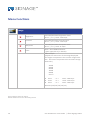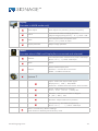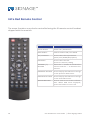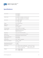
1
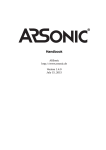
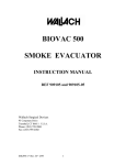
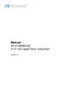
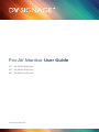
Pro-AV Monitor User Guide
32” PA-3200-0200-0xxx
40” PA-4000-0200-0xxx
46” PA-4600-0200-0xxx
www.dvsignage.com
2
Pro-AV Monitor User Guide | © DV Signage 2011
Contents
Important Safeguards
4
ROHS Notice
9
Package Contents
10
Set Up Procedure
10
Monitor Operating Environment
11
Monitor Connections
12
Menu Functions
13
IR Remote
16
Specifications
17
AC Power
18
Mode Support Table
ARGB Modes
19
HDMI Port
20
DisplayPort
21
Monitor Dimensions
22
Warranty
26
Cautions
27
Limitation of Liability
27
Trademarks
27
Contact Details
28
www.dvsignage.com
3
Important Safeguards
In addition to the careful attention devoted to quality standards in the
manufacture process of your display product, safety is a major factor in the
design of every instrument. However, safety is your responsibility too. This sheet
lists important information that will help to assure your enjoyment and proper
use of the display product and accessory equipment. Please read them carefully
before operating and using your display product.
Installation
Read and Follow Instructions - All the safety and operating instructions should
be read before the display monitor is operated. Follow all operating instructions.
1. Retain Instructions - The safety and operating instructions should be retained
for future reference.
2. Heed Warnings - Comply with all warnings on the video product and in the
operating instructions.
3. Polarization - Do not defeat the safety purpose of the grounding-type
plug.
A grounding type plug has two blades and a third grounding
prong. The wide blade or the third prong are provided for
your safety.
If the provided plug does not fit into your outlet, consult an
electrician for replacement of the obsolete outlet
4
Pro-AV Monitor User Guide | © DV Signage 2011
5. Power Sources - This display product should be operated only from the type
of power source indicated on the marking label. If you are not sure of the type of
power supply to your location, consult your video dealer or local power
company.
6. Overloading - Do not overload wall outlets of extension cords as this can result
in the risk of fire or electric shock. Overloaded AC outlets, extension cords, frayed
power cords, damaged or cracked wire insulation, and broken plugs are
dangerous. They may result in a shock or fire hazard. Periodically examine the
cord, and if its appearance indicates damage or deteriorated insulation, have it
replaced by your service technician.
7. Power-Cord Protection - Power supply cords should be routed so that they
are not likely to be walked on or pinched by items placed upon or against them,
paying particular attention to cords at plugs, convenience receptacles, and the
point where they exit from the display product.
8. Ventilation - Slots and openings in the case are provided for ventilation to
ensure reliable operation of the video product and to protect it from
overheating. These openings must not be blocked or covered. The openings
should never be blocked by placing the display equipment on a bed, sofa, rug, or
other similar surface. This display product should never be placed near or over a
radiator or heat register. This display product should not be placed in a built-in
installation such as a bookcase or rack unless proper ventilation is provided or
the video product manufacturer’s instructions have been followed.
9. Attachments - Do not use attachments unless recommended by the display
product manufacturer as they may cause a hazard.
www.dvsignage.com
5
10. Water and Moisture - Do not use this display product near water. For
example, near a bath tub, wash bowl, kitchen sink or laundry tub, in a wet
basement, near a swimming pool and the like.
11. Accessories - Do not place this display equipment on an
unstable cart, stand, tripod, or table. The display equipment
may fall, causing serious damage to the display product. Use
this display product only with a cart, stand, tripod, bracket,
or table recommended by the manufacturer or sold with the
display product. Any mounting of the product should follow the manufacturer’s
instructions and use a mounting accessory recommended by the manufacturer.
12 Wall or Ceiling Mounting - The display product should be mounted to a wall
or ceiling only as instructed in this guide, using the provided mounting bracket
Service
13. Servicing - Do not attempt to service this display equipment yourself as
opening or removing covers may expose you to dangerous voltage or other
hazards. Refer all servicing to qualified service personnel.
14. Conditions Requiring Service - Unplug this display product from the wall
outlet and refer servicing to qualified service personnel under the following
conditions.
A. When the power supply cord or plug is damaged.
B. If liquid has been spilled or objects have fallen into the display
product.
6
Pro-AV Monitor User Guide | © DV Signage 2011
C. If the display product has been exposed to rain or water.
D. If the display product does not operate normally by following the
operating instructions. Adjust only those controls that are covered by
the operating instructions. Improper adjustment of other controls may
result in damage and will often require extensive work by a qualified
technician to restore the video product to its normal operation.
E. If the display product has been dropped or the cabinet has been
damaged.
F. When the display product exhibits a distinct change in performance.
This indicates a need for service.
15. Replacement Parts - When replacement parts are required, have the service
technician verify that the replacements used have the same safety
characteristics as the original parts. Use of replacements specified by the display
product manufacturer can prevent fire, electric shock or other hazards.
16. Safety Check - Upon completion of any service or repairs to this display
product, ask the service technician to perform safety checks recommended by
the manufacturer to determine that the display product is in safe operating
condition.
17. Heat - The product should be situated away from heat sources such as
radiators, heat registers, stoves, or other products (including amplifiers) that
produce heat.
www.dvsignage.com
7
Use
19. Cleaning - Unplug the display product from the wall outlet before cleaning.
Do not use liquid cleaners or aerosol cleaners. Use a damp or dry cloth for
cleaning.
20. Product and Cart Combination - display and cart combination should be
moved with care. Quick stops, excessive force, and uneven surfaces may cause
the display product and car combination to overturn.
21. Object and Liquid Entry - Never push objects for any kind into this display
product through openings as they may touch dangerous voltage points or
“short-out” parts that could result in a fire or electric shock. Never spill liquid of
any kind on the display product.
22. Lightning - For added protection for this display product during a lightning
storm, or when it is left unattended and unused for long periods of time, unplug
it from the wall outlet and disconnect the antenna or cable system. This will
prevent damage to the display product due to lightning and power line surges.
23. To reduce the risk of fire or electric shock do not expose this display product
to rain or moisture
24. Battery (Lithium) on the main board is not intended to be replaced by user.
Caution (A) To reduce the risk of electric shock do not perform any
servicing other than that contained in the operating instruction unless
you are qualified to do so. (B) Danger of explosion if battery is
incorrectly replaced
25. WARNING To prevent injury, this display product must be securely
attach to the floor/wall in accordance with the manufacture
installation instructions.
8
Pro-AV Monitor User Guide | © DV Signage 2011
Declaration of RoHS Compliance
This product has been designed and manufactured in compliance with Directive
2002/ /95/EC of the European Parliament and the Council on restriction of the
use of certain hazardous substances in electrical and electronic equipment (RoHS
Directive) and is deemed to comply with the maximum concentration values
issued by the European Technical Adaptation Committee (TAC) as shown below:
Certain components of products as stated above are exempted under the Annex
of the RoHS Directives as noted below:
Examples of exempted components are:
1. Mercury in compact fluorescent lamps not exceeding 5 mg per lamp and in
other lamps not specifically mentioned in the Annex of RoHS Directive.
2. Lead in glass of cathode ray tubes, electronic components, fluorescent tubes,
and electronic ceramic parts (e.g. piezoelectronic devices).
3. Lead in high temperature type solders (i.e. lead-based alloys containing 85%
by weight or more lead).
4. Lead as an allotting element in steel containing up to 0.35% lead by weight,
aluminium containing up to 0.4% lead by weight and as a cooper alloy containing
up to 4% lead by weight.
www.dvsignage.com
9
Package Contents
The shipping carton will contain the following parts:
•
•
•
•
LCD monitor
Remote Control
AC Power cable
AAA battery (x 2)
Note: The shipping carton and packaging materials should be retained in case
the monitor should need to be reshipped for any reason.
Setup Procedure
1. Determine the installation location.
CAUTION: DO NOT ATTEMPT TO INSTALL THE LCD MONITOR BY YOURSELF.
Installation of your LCD monitor must be performed by a qualified technician.
Contact your dealer for more information.
CAUTION: MOVING OR INSTALLING THE LCD MONITOR MUST BE DONE BY TWO
OR MORE PEOPLE. Failure to follow this caution may result in injury if the LCD
monitor falls.
CAUTION: The front surface of the monitor’s LCD panel is delicate and should not
be laid face down unless a protective cushion is in place.
2. Connect external equipment
To protect the connected equipment, turn off the main power before making
connections. Refer to your equipment user manual.
10
Pro-AV Monitor User Guide | © DV Signage 2011
3. Connect the supplied power cord
The power outlet socket should be installed as near to the equipment as
possible, and should be easily accessible. NOTE: • Please refer to “Safety
Precautions, Maintenance & Recommended Use” section of this manual for
proper selection of the AC power cord.
4. Turn on AC Power Switch
Turn on the AC power switch adjacent to the power input connector on the
monitor. The switch will illuminate to show a red light when the AC power is on.
5. Enable the video display
Using the menu function, select the input signal to be displayed.
6. Adjust the sound
Using the menu function, make adjustments to the volume as required.
7. Adjust the screen
Using the menu function, make adjustments to the display position or settings
if required.
8. Adjust the image
Using the menu function, make adjustments to brightness or contrast if required.
Monitor Operating Environment
The monitor is designed to function in the following ambient environment:
Operational
Humidity
www.dvsignage.com
Temperature 0C° - 40C°, 32° - 104°F
20 - 80% (without condensation)
11
Monitor Connections
The monitor is provided with a number of different input ports. The following
identifies the ports and their purpose.
DVI Port
Digital Video Input port, suitable to connect any PC or equipment with a compatible digital output.
HDMI
High Definition Multimedia Interface, suitable to connect any
compatible equipment such as BluRay players etc.
VGA
Video Graphics Array interface, suitable to connect any compatible device such
as PC with a VGA output
Serial
RS-232 serial interface. Used to load monitor operating code by qualified
personnel. Contact your dealer for information
Audio Out
Speaker jacks. HDMI amplified output.
12
Pro-AV Monitor User Guide | © DV Signage 2011
Menu Control Functions
The monitor configuration can be controlled by either the IR remote control
shipped with the monitor, or by the user buttons located on the rear of the cover.
1
2
3
4
5
6
7
8
1. Power On/Off : Turns On and Off the power to the monitor electronics.
Note : There is a separate AC power switch on the rear of the unit that must be turned on before this
button can operate. The monitor is configured to automatically turn on when AC power is connected.
2. Adjust Up : Increments the value of the currently selected menu field.
3. Adjust Down : Decrements the value of the currently selected menu field.
4. Select Up : Moves the menu field selection up. The selection rolls over at the
top of the menu to select the bottom item.
5. Select Down : Moves the menu field selection down. The selection rolls over
at the bottom of the menu to select the top item.
6. Menu : Enables and disables the display of the On Screen user menu.
7. Backlight Up : Increments the backlight setting to brighten the screen display.
8. Backlight Down : Decrements the backlight setting to dim the screen display.
www.dvsignage.com
13
Menu Functions
Image
Brightness
Increase/decrease brightness level.
Press [- or + ] Total : 100 steps
Contrast
Increase/decrease contrast level.
Press [- or + ] Total : 100 steps
Sharpness
Increase/decrease sharpness level.
Press [- or + ] Total : 8 steps
Color
Auto : Auto RGB Calibration
( [See appendix IV] in details)
Color temp Ṗ
(Adjust the warmness of the image displayed.
The higher temperature the coolest image looks
like. The lower temperature the warmest image
looks like.)
4200k
5000k
6500k
7500k
9300k
User Ṗ
R
G
B
Press
Press
Press
- or +
- or +
- or +
Total : 100 steps
Total : 100 steps
Total : 100 steps
Gamma (0.4/0.6/1.0/1.6/2.2)
Items marked Ṗ have sub menus.
Exit the OSD menu to save the setting chosen
14
Pro-AV Monitor User Guide | © DV Signage 2011
Display
(Function in ARGB mode only)
Auto Adjust
Auto adjust the position, phrase, frequency
Phase
Fine tune the data sampling position
(adjust image quality) Press [ – or + ] Total : 100
Clock
Increase/decrease sharpness level.
Press [- or + ] Total : 8 steps
Display Position
Adjust image position
Sound
(Function when HDMI and DisplayPort connected and selected)
Volume
Increase/decrease volume level, total: 100 steps
Press – or + (- + ) Total : 100 steps
Mute
Mute
Output
Select audio output port
Speakers : via CN1 & J1 connector
SPDIF : via CN11 connector
System Ṗ
Input : Select the input video signal
Display Port | VGA | DVI/HDMI
Autoscan : Enable the Auto source seek function
Timer : OSD Timeout in seconds
3 sec | 6 sec | 12 sec | Always On
Rotation : OSD menu rotation in degree
0 | 90 | 180 | 270
Position : Adjust OSD menu position
Transparency : Set OSD transparency
Press – or + (+ ) Total : 100 steps
Reset : Load factory default settings.
Press down on OSD keypad to factory reset
www.dvsignage.com
15
Infra Red Remote Control
The menu functions may also be controlled using the IR remote control handset
shipped with the monitor.
16
Button
Function
Power Button
Power ON / OFF Button
Mute Button
Switch to Mute ON / OFF Mode
AV / TV Button
Use to select the Input Source
(VGA / DVI/ HDMI/DisplayPort)
PIP Button
Use to select the PIP
(Picture in Picture) setting
VOLUME (-/+)
BUTTON
Press the “+” button to increase the
volume and the “-” to decrease the
volume.
OSD BACK BUTTON
Use to display the OSD menu and go
to the previous OSD screen.
OSD NEXT BUTTON
Use to display the OSD menu and go
to the next OSD screen.
DISPLAY BUTTON
Use to view an on-screen information. When OSD menu displayed,
press this button to turn it off.
Pro-AV Monitor User Guide | © DV Signage 2011
Specifications
Screen Size
46” Diagonal
40” Diagonal
32” Diagonal
Active Area
46”=1025.4 x 578.6mm, 40.37 x 22.77”
40”= 891.7 x 504.2mm, 35.1 x 19.85”
32”= 703.6 x 398.4mm, 27.7 x 15.68”
Resolution
46”,=1920 x 1080
40” =1920 x 1080
32” = 366 x 768
Colors
Up to 16.7M colors
Brightness
450 cd/m
Contrast
46”/40” = 4000:1
32” = 3500:1
Viewing Angle
178° Up, Down, Left Right
Video inputs
ARGB,15 Pin D-sub connector
DVI-D, DVI-D connector
HDMI, connector
Serial Port
9 Pin D Sub, 9600 baud, 8N1
Audio Out
Audio Jacks, stereo 2W per channel
User Controls
Menu Buttons, Remote control
Power management
VESA DPMS
Plug & Play
VESA DDC2B
Input Power
100 – 240V AC, 50/60Hz
Power Consumption
40”/46” =178W
32” = 87W
Operating Environment
0 – 40C°
Storage Environment
-10 +60C°
Dimensions
46” = 1094.2 x 638.14 x 86.03mm 43 x 25.12 x 3.38”
40” = 922.9 x 535.4 x 104.12mm 36.33 x 21.07 x 4.09”
32” = 771 461.7 x 95.2mm
30.5 x 18.17 x 3.74”
Weight
46” = 22.6Kg, 49.6lb
40” = 22.6Kg, 49.6lb
32” = 15.8Kg, 34.8lb
www.dvsignage.com
17
AC Power
The power supply is auto-ranging and supports an input voltage range of 100 –
240VAC, 50/60Hz. All models have a common A/C power connector which
accepts a standard IEC60320 style power cord. The Inlet/switch module also has
an integrated replaceable fuse holder with a 250V Slow Blow fuse.
32” Models: Type T5AL250V Rated 5A
40” Models: Type T8AL250V, Rated 8A
46” Models: Type T8AL250V, Rated 8A
CAUTION :
For continued protection against risk of fire, replace only with same type
and rating of fuse
Warning :
Operating Temperature. This product is designed for a maximum ambient temperature of 40° degrees C.
General Precautions :
1. All warnings and instructions of this manual should be followed
2. Remove the plug from the outlet before cleaning. Do not use liquid aerosol
detergents. Use a water dampened cloth or dry cloth for cleaning
3. Do not use this unit in humid or wet places
4. Keep enough space around the unit for ventilation. Slots and openings in the
storage cabinet should not be blocked
5. During lightning storms, or when the unit is not used for a long time,
disconnect the power supply, antenna, and cables to protect the unit from electrical surge
18
Pro-AV Monitor User Guide | © DV Signage 2011
Appendix I – Mode Support Table
Mode
Resolution
Clk [MHz]
Horizontal
freq [KHz]
Vertical
freq [Hz]
Sync Mode
T_70
720x400 70Hz
28.322
31.469
70.087
Digital Separate Sync
T_70
720x400 70Hz
28.322
31.469
70.087
Sync On Green
V_60
640x480 60Hz
25.175
31.469
59.940
Digital Separate Sync
V_60
640x480 60Hz
25.175
31.469
59.940
Sync On Green
V_60
640x480 60Hz
25.175
31.469
59.940
Composite Sync
SV_60
800x600 60Hz
40.000
37.879
60.317
Digital Separate Sync
SV_60
800x600 60Hz
40.000
37.879
60.317
Sync On Green
SV_60
800x600 60Hz
40.000
37.879
60.317
Composite Sync
X_60
1024x768 60Hz
65.000
48.363
60.004
Digital Separate Sync
X_60
1024x768 60Hz
65.000
48.363
60.004
Sync On Green
X_60
1024x768 60Hz
65.000
48.363
60.004
Composite Sync
SX_60
1280x1024 60Hz
108
63.81
60.020
Digital Separate Sync
SX_60
1280x1024 60Hz
108
63.81
60.020
Sync On Green
SX_60
1280x1024 60Hz
108
63.81
60.020
Composite Sync
UX_60
1600x1200 60Hz
162
75.000
60
Digital Separate Sync
UX_60
1600x1200 60Hz
162
75.000
60
Sync On Green
UX_60
1600x1200 60Hz
162
75.000
60
Composite Sync
WUX_60
1920x1080 60Hz
172.8
67.5
60
Digital Separate Sync
WUX_60
1920x1080 60Hz
172.8
67.5
60
Sync On Green
WUX_60
1920x1080 60Hz
172.8
67.5
60
Composite Sync
WUX_60
1920x1200 60Hz
193.2
74.5
60
Digital Separate Sync
WUX_60
1920x1200 60Hz
193.2
74.5
60
Sync On Green
WUX_60
1920x1200 60Hz
193.2
74.5
60
Composite Sync
www.dvsignage.com
19
HDMI
Resolution
Clk [MHz]
Horizontal freq
[KHz]
Vertical freq
[Hz]
T_70
720x400 70Hz
28.322
31.469
70.087
V_60
640x480 60Hz
25.175
31.469
59.940
SV_60
800x600 60Hz
40.000
37.879
60.317
X_60
1024x768 60Hz
65.000
48.363
60.004
SX_60
1280x1024 60Hz
108
63.81
60.020
UX_60
1600x1200 60Hz
162
75.000
60
WUX_60
1920x1080 60Hz
172.8
67.5
60
WUX_60
1920x1200 60Hz
193.2
74.5
60
1080p60
1920x1080p 60Hz
135
67.5
60
1080i60
1920x1080i 60Hz
74.14
33.7
60
1080i50
1920x1080i 50Hz
74.184
28.1
50
720p60
1280x720P 60Hz
74.25
45
60
576p50
720x576P 50Hz
26.9568
31.2
50
480p60
720x480P 60Hz
26.9568
31.4
60
Mode
20
Pro-AV Monitor User Guide | © DV Signage 2011
DisplayPort
Mode
Resolution
Clk [MHz]
Horizontal freq
[KHz]
Vertical freq [Hz]
T_70
720x400 70Hz
28.322
31.469
70.087
V_60
640x480 60Hz
25.175
31.469
59.940
SV_60
800x600 60Hz
40.000
37.879
60.317
X_60
1024x768 60Hz
65.000
48.363
60.004
SX_60
1280x1024 60Hz
108
63.81
60.020
UX_60
1600x1200 60Hz
162
75.000
60
WUX_60
1920x1080 60Hz
172.8
67.5
60
WUX_60
1920x1200 60Hz
193.2
74.5
60
1080p60
1920x1080p 60Hz
135
67.5
60
1080i60
1920x1080i 60Hz
74.14
33.7
60
1080i50
1920x1080i 50Hz
74.184
28.1
50
720p60
1280x720P 60Hz
74.25
45
60
576p50
720x576P 50Hz
26.9568
31.2
50
480p60
720x480P 60Hz
26.9568
31.4
60
www.dvsignage.com
21
PORTRAIT
PORTRAIT
PORTRAIT
LANDSCAPE
LANDSCAPE
PORTRAIT
LANDSCAPE
LANDSCAPE
POR
LANDSCAPE
PORTRAIT
Fig 1. 46” Monitor
336.4 [13.24]
126 [4.96]
1,094.2 [43.077]
1,025.4 [40.370]
46”
638.14 [25.124]
578.6 [22.780]
29.8 [1.172]
34.4 [1.353]
600
200
200
395 [15.55]
22
200
200
200
200
Pro-AV Monitor User Guide | © DV Signage 2011
PORTRAIT
LANDSCAPE
PORTRAIT
PORTRAIT
LANDSCAPE
PORTRAIT
LANDSCAPE
LANDSCAPE
POR
LANDSCAPE
PORTRAIT
Fig 2. 40” Monitor
922.9 [36.333]
891.7 [35.106]
40”
535.4 [21.077]
504.2 [19.850]
15.6 [.613]
200
200
200
200
200
200
600
129.8 [5.11]
www.dvsignage.com
23
PORTRAIT
PORTRAIT
PORTRAIT
LANDSCAPE
LANDSCAPE
PORTRAIT
LANDSCAPE
LANDSCAPE
POR
LANDSCAPE
PORTRAIT
Fig 3. 32” Monitor
Note: The mounting for the VESA 400mm footprint on the 32” model is
not centrally located. Review the dimensions before installing.
120.3 [4.73]
57.2 [2.25]
771.7 [30.380]
461.7
[18.176]
32”
34
[1.340]
703.6 [27.701]
398.4 [15.685]
31.6 [1.246]
120
[4.72]
200
200
200
200
200
336.4
[13.24]
200
395 [15.55]
24
Pro-AV Monitor User Guide | © DV Signage 2011
Mounting the Monitor
The monitors each provides two sets of mounting points:
400mm x 400mm VESA:
On the rear panel of the monitor a 400 x 400 mm VESA standard mounting
pattern is provided. Mounting screw size M6
600 x 200mm VESA:
The monitor also supports mounting points on the rear panel suitable for use
with a wide range of wall mounts. Mounting screw size M6
Note:
The monitors are fully compatible to a wide range of commercially available
mounting systems that support the VESA standards.
Safety Note:
It is imperative that the rating of any mounting system be checked
to ensure that is adequately specified to support the weight of the
monitor. All rules regarding safety and installation supplied along with
the mounting system must be followed precisely to prevent possible
damage or injury.
www.dvsignage.com
25
WARRANTY
The products are warranted against defects in workmanship and material for a
period of one (1) year from the date of purchase provided no modifications are
made to it and it is operated under normal conditions and in compliance with
the instruction manual.
The warranty does not apply to:
»»
»»
»»
»»
Product that has been installed incorrectly, this specifically includes but is
not limited to cases where electrical short circuit is caused.
Product that has been altered or repaired except by the manufacturer (or
with the manufacturer’s consent).
Product that has subjected to misuse, accidents, abuse, negligence or
unusual stress whether physical or electrical.
Ordinary wear and tear.
Except for the above express warranties, the manufacturer disclaims all
warranties on products furnished hereunder, including all implied warranties of
merchantability and fitness for a particular application or purpose. The stated
express warranties are in lieu of all obligations or liabilities on the part of the
manufacturer for damages, including but not limited to special, indirect
consequential damages arising out of or in connection with the use of or
performance of the products.
26
Pro-AV Monitor User Guide | © DV Signage 2011
CAUTION
Whilst care has been taken to provide as much detail as possible for use of this
product it cannot be relied upon as an exhaustive source of information. This
product is for use by suitably qualified persons who understand the nature of
the work they are doing and are able to take suitable precautions and design
and produce a product that is safe and meets regulatory requirements.
In the interest of continuing product improvement, DV Signage reserves the
right to change product specifications without notice. Information in this
document may change without notice.
No part of this document may be copied, reproduced, or transmitted by any
means, for any purpose without prior written permission from DV Signage.
LIMITATION OF LIABILITY
The manufacturer’s liability for damages to customer or others resulting from
the use of any product supplied hereunder shall in no event exceed the
purchase price of said product.
Disclaimer: DV Signage shall not be liable for technical or editorial errors or
omissions contained herein; nor for incidental or consequential damages
resulting from furnishing this material, or the performance or use of this
product.
TRADEMARKS
VESA is a registered trademark of the Video Electronics Standards Association.
DPMS and DDC are trademarks of VESA.
www.dvsignage.com
27
Office Details
USA
DV Signage Inc.
18440 Technology Dr.
Building 130
Morgan Hill, CA 95037, USA
T: +1-408-782-7773 | F: +1-408-782-7883
[email protected]
Europe
DV Signage Europe GmbH.
Landshuter Allee 162a,
D 80637 Munich
Germany
T: +49-(0)89 143 47 52-0 | F: +49-(0)89 143 47 52-30
[email protected]
Hong Kong
DV Signage Ltd.
16th floor Millennium City 3
370 Kwun Tong Road
Kwun Tong, HONG KONG
T: +852-2861-3615 | F: +852-2520-2987
[email protected]
www.dvsignage.com