1
Multi-Range DC Power Supply
PSW Series
PROGRAMMING MANUAL
VERSION: 1.4
ISO-9001 CERTIFIED MANUFACTURER
This manual contains proprietary information, which is protected by
copyright. All rights are reserved. No part of this manual may be
photocopied, reproduced or translated to another language without
prior written consent of Good Will company.
The information in this manual was correct at the time of printing.
However, Good Will continues to improve products and reserves the
rights to change specification, equipment, and maintenance
procedures at any time without notice.
Good Will Instrument Co., Ltd.
No. 7-1, Jhongsing Rd., Tucheng Dist., New Taipei City 236, Taiwan.
Table of Contents
Table of Contents
SAFETY INSTRUCTIONS ................................................... 4
GETTING STARTED ........................................................... 8
PSW Series Overview ............................. 9
Appearance .......................................... 14
Configuration Settings ......................... 21
REMOTE CONTROL ........................................................ 29
Interface Configuration ........................ 30
Socket Server Examples ....................... 45
Command Syntax ................................. 49
Command List ..................................... 52
Status Register Overview ..................... 94
Error List ........................................... 105
APPENDIX ..................................................................... 114
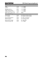
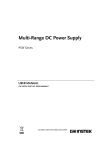
PSW Default Settings ......................... 114
Error Messages & Messages .............. 117
LED Display Format ........................... 117
INDEX............................................................................ 118
3
PSW Series Programming Manual
SAFETY INSTRUCTIONS
This chapter contains important safety
instructions that you must follow during
operation and storage. Read the following before
any operation to insure your safety and to keep
the instrument in the best possible condition.
Safety Symbols
These safety symbols may appear in this manual or on the
instrument.
WARNING
Warning: Identifies conditions or practices that
could result in injury or loss of life.
CAUTION
Caution: Identifies conditions or practices that
could result in damage to the PSW or to other
properties.
DANGER High Voltage
Attention Refer to the Manual
Protective Conductor Terminal
Earth (ground) Terminal
4
SAFETY INSTRUCTIONS
Do not dispose electronic equipment as unsorted
municipal waste. Please use a separate collection
facility or contact the supplier from which this
instrument was purchased.
Safety Guidelines
General
Guideline
CAUTION
Do not place any heavy object on the PSW.
Avoid severe impact or rough handling that
leads to damaging the PSW.
Do not discharge static electricity to the PSW.
Use only mating connectors, not bare wires, for
the terminals.
Do not block the cooling fan opening.
Do not disassemble the PSW unless you are
qualified.
(Measurement categories) EN61010-1:2010 and EN61010-2-030
specify the measurement categories and their requirements as
follows. The PSW falls under category II.
Measurement category IV is for measurement performed at the
source of low-voltage installation.
Measurement category III is for measurement performed in the
building installation.
Measurement category II is for measurement performed on the
circuits directly connected to the low voltage installation.
0 is for measurements performed on circuits not directly
connected to Mains.
Power Supply
WARNING
AC Input voltage range: 85VAC~265VAC
Frequency: 47Hz~63Hz
To avoid electrical shock connect the protective
grounding conductor of the AC power cord to
an earth ground.
5
PSW Series Programming Manual
Cleaning the PSW
Operation
Environment
Disconnect the power cord before cleaning.
Use a soft cloth dampened in a solution of mild
detergent and water. Do not spray any liquid.
Do not use chemicals containing harsh material
such as benzene, toluene, xylene, and acetone.
Location: Indoor, no direct sunlight, dust free,
almost non-conductive pollution (Note below)
Relative Humidity: 20%~ 85%
Altitude: < 2000m
Temperature: 0°C to 50°C
(Pollution Degree) EN61010-1:2010 and EN61010-2-030 specify the
pollution degrees and their requirements as follows. The PSW falls
under degree 2.
Pollution refers to “addition of foreign matter, solid, liquid, or
gaseous (ionized gases), that may produce a reduction of dielectric
strength or surface resistivity”.
Pollution degree 1: No pollution or only dry, non-conductive
pollution occurs. The pollution has no influence.
Pollution degree 2: Normally only non-conductive pollution
occurs. Occasionally, however, a temporary conductivity caused
by condensation must be expected.
Pollution degree 3: Conductive pollution occurs, or dry, nonconductive pollution occurs which becomes conductive due to
condensation which is expected. In such conditions, equipment
is normally protected against exposure to direct sunlight,
precipitation, and full wind pressure, but neither temperature
nor humidity is controlled.
Storage
environment
Disposal
6
Location: Indoor
Temperature: -25°C to 70°C
Relative Humidity: <90%
Do not dispose this instrument as unsorted
municipal waste. Please use a separate collection
facility or contact the supplier from which this
instrument was purchased. Please make sure
discarded electrical waste is properly recycled to
reduce environmental impact.
SAFETY INSTRUCTIONS
Power cord for the United Kingdom
When using the power supply in the United Kingdom, make sure
the power cord meets the following safety instructions.
NOTE: This lead/appliance must only be wired by competent persons
WARNING: THIS APPLIANCE MUST BE EARTHED
IMPORTANT: The wires in this lead are coloured in accordance with the
following code:
Green/ Yellow:
Earth
Blue:
Neutral
Brown:
Live (Phase)
As the colours of the wires in main leads may not correspond with
the coloured marking identified in your plug/appliance, proceed
as follows:
The wire which is coloured Green & Yellow must be connected to
the Earth terminal marked with either the letter E, the earth symbol
or coloured Green/Green & Yellow.
The wire which is coloured Blue must be connected to the terminal
which is marked with the letter N or coloured Blue or Black.
The wire which is coloured Brown must be connected to the
terminal marked with the letter L or P or coloured Brown or Red.
If in doubt, consult the instructions provided with the equipment
or contact the supplier.
This cable/appliance should be protected by a suitably rated and
approved HBC mains fuse: refer to the rating information on the
equipment and/or user instructions for details. As a guide, a cable
of 0.75mm2 should be protected by a 3A or 5A fuse. Larger
conductors would normally require 13A types, depending on the
connection method used.
Any exposed wiring from a cable, plug or connection that is
engaged in a live socket is extremely hazardous. If a cable or plug is
deemed hazardous, turn off the mains power and remove the cable,
any fuses and fuse assemblies. All hazardous wiring must be
immediately destroyed and replaced in accordance to the above
standard.
7
PSW Series Programming Manual
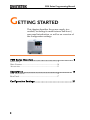
GETTING STARTED
This chapter describes the power supply in a
nutshell, including its main features and front /
rear panel introduction, as well as an overview of
the configuration settings.
PSW Series Overview ......................................................... 9
Series lineup .............................................................................. 9
Main Features ......................................................................... 10
Accessories ............................................................................. 11
Appearance ..................................................................... 14
PSW Front Panel ................................................................... 14
Rear Panel ............................................................................... 17
Configuration Settings..................................................... 21
8
GETTING STARTED
PSW Series Overview
Series lineup
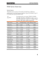
The PSW series consists of 15 models, divided into 3 different
model types covering 3 power capacities: Type I (360 Watt), Type II
(720 Watt) and Type III (1080 Watt).
Note
Throughout the user manual, PSW 30, PSW 80,
PSW 160, PSW 250 or PSW 800 will refer to any of
the PSW models with a maximum voltage rating of
30V, 80V, 160V, 250V or 800V, respectively.
Model name
Type
Voltage Rating Current Rating Power
PSW 30-36
Type I
0~30V
0~36A
360W
PSW 80-13.5
Type I
0~80V
0~13.5A
360W
PSW 160-7.2
Type I
0~160V
0~7.2A
360W
PSW 250-4.5
Type I
0~250V
0~4.5A
360W
PSW 800-1.44
Type I
0~800V
0~1.44A
360W
PSW 30-72
Type II 0~30V
0~72A
720W
PSW 80-27
Type II 0~80V
0~27A
720W
PSW 160-14.4
Type II 0~160V
0~14.4A
720W
PSW 250-9
Type II 0~250V
0~9A
720W
PSW 800-2.88
Type II 0~800V
0~2.88A
720W
PSW 30-108
Type III 0~30V
0~108A
1080W
PSW 80-40.5
Type III 0~80V
0~40.5A
1080W
PSW 160-21.6
Type III 0~160V
0~21.6A
1080W
PSW 250-13.5
Type III 0~250V
0~13.5A
1080W
PSW 800-4.32
Type III 0~800V
0~4.32A
1080W
9
PSW Series Programming Manual
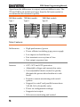
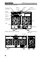
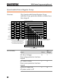
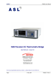
Apart from the differences in output, each unit differs in size. The
720 and 1080 watt models are larger than the 360 watt models to
accommodate the increase in power.
360 Watt models 720 Watt models
1080 Watt models
Type I
Type III
PSW 30-36
Type II
Multi-Range DC Power Supply
360W
VSR
Voltage
PSW 30-72
ALM
Multi-Range DC Power Supply
720W
VSR
W
CV
Voltage
PSW 30-108
40
60
80
100
%W
DLY
ALM
Current
Function
OVP/OCP
Set
Test
Lock/Local
PWR DSPL
40
60
80
100
%W
Function
OVP/OCP
Set
Test
Lock/Local
PWR DSPL
ALM
20
40
60
80
100
Current
W
A
ISR
Output
%W
DLY
CC
A
ISR
Output
Current
W
CC
A
ISR
V
RMT
20
DLY
W
CC
Voltage
W
CV
V
RMT
20
Multi-Range DC Power Supply
1080W
VSR
W
CV
V
RMT
Function
OVP/OCP
Set
Test
Lock/Local
PWR DSPL
Output
Main Features
Performance
Features
10
High performance/power
Power efficient switching type power supply
Low impact on load devices
Fast transient recovery time of 1ms
Fast output response time
OVP, OCP and OTP protection
Adjustable voltage and current slew rates
User adjustable bleeder control to quickly
dissipate the power after shutdown to safe
levels.
Extensive remote monitoring and control
options
Support for serial* and parallel connections.
*(30, 80, 160 volt models only)
Power on configuration settings.
Supports test scripts
Web server monitoring and control
GETTING STARTED
Interface
Ethernet port
Analog connector for analog voltage and current
monitoring
USB host and device port
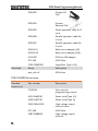
Accessories
Please check the contents before using the PSW.
PSW 30/80/160 Accessories
Standard
Accessories
Part number
Description
CD-ROM
User manual,
programming manual
4323-30600101
Power cord (Type I/II)
4320-91001101
Power cord (Type III)
1042-SWLV0301
Output terminal cover
GTL-123
Test leads: 1x red, 1x black
GTL-240
USB Cable
PSW-004
Basic Accessory Kit:
M4 terminal screws and
washers x2, M8 terminal
bolts, nuts and washers x2,
Air filter x1, Analog control
protection dummy x1,
Analog control lock level x1
Optional
Accessories
Part number
Description
GET-001
Extended terminal
PSW-001
Accessory Kit:
Pin contact x10, Socket x1,
Protection cover x1
11
PSW Series Programming Manual
Download
PSW-002
Simple IDC
Tool
PSW-003
Contact
Removal Tool
PSW-005
Series operation cable for 2
units.
PSW-006
Parallel operation cable for
2 units.
PSW-007
Parallel operation cable for
3 units.
GRA-410-J
Rack mount adapter (JIS)
GRA-410-E
Rack mount adapter (EIA)
GUG-001
GPIB to USB adapter
GTL-240
USB Cable
57RG-30B00201
Large filter (Type II/III)
Name
Description
psw_cdc.inf
USB driver
PSW 250/800 Accessories
Standard
Accessories
12
Part number
Description
CD-ROM
User manual,
programming manual
4323-30600101
Power cord (Type I/II)
4320-91001101
Power cord (Type III)
1042-SWHV0301
High voltage output
terminal cover
GTL-240
USB Cable
39BT-50900401
High voltage output
terminal
GETTING STARTED
PSW-008
Basic Accessory Kit:
(Air filter x1, Analog control
protection dummy x1,
Analog control lock level x1
Optional
Accessories
Part number
Description
GET-002
Extended terminal
PSW-001
Accessory Kit:
Pin contact x10, Socket x1,
Protection cover x1
Download
PSW-002
Simple IDC
Tool
PSW-003
Contact
Removal Tool
PSW-006
Parallel operation cable for
2 units.
PSW-007
Parallel operation cable for
3 units.
GRA-410-J
Rack mount adapter (JIS)
GRA-410-E
Rack mount adapter (EIA)
GTL-130
Test leads: 2x red, 2x black
GUG-001
GPIB to USB adapter
GTL-240
USB Cable
57RG-30B00201
Large filter (Type II/III)
Name
Description
psw_cdc.inf
USB driver
13
PSW Series Programming Manual
Appearance
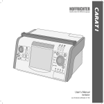
PSW Front Panel
720W: PSW 30-72, 80-27, 160-14.4, 250-9, 800-2.88
PSW 30-72
Display
Multi-Range DC Power Supply
720W
VSR
Voltage
Voltage
knob
Current
Current
knob
W
CV
V
RMT
ALM
20
40
60
80
100
%W
DLY
W
CC
A
ISR
Cover
panel
Function
OVP/OCP
Set
Test
Lock/Local
PWR DSPL
Output
key
Output
Power
switch
Function
keys
USB A
port
1080W: PSW 30-108, 80-40.5, 160-21.6,
250-13.5, 800-4.32
PSW 30-108
360W: PSW 30-36,
80-13.5, 160-7.2,
250-4.5, 800-1.44
Multi-Range DC Power Supply
1080W
VSR
Voltage
PSW 30-36
V
RMT
20
40
60
80
100
%W
DLY
Current
W
CC
Function
OVP/OCP
Set
Test
Lock/Local
PWR DSPL
ALM
20
40
60
80
100
Current
W
A
ISR
Output
%W
DLY
CC
A
ISR
14
Voltage
W
CV
V
RMT
ALM
Multi-Range DC Power Supply
360W
VSR
W
CV
Function
OVP/OCP
Set
Test
Lock/Local
PWR DSPL
Output
GETTING STARTED
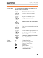
Function Keys
The Function keys along with the Output key will
light up when a key is active.
Function
OVP/OCP
Display
Indicators
The Function key is used to
configure the power supply.
Set the over current or over
voltage protection levels.
Set
Sets the current and voltage limits.
Test
Used to run customized scripts for
testing.
Lock/Local
Locks or unlocks the panel keys to
prevent accidentally changing
panel settings.
PWR DSPL
Toggles the display from viewing
V/AV/WA/W.
VSR
Voltage Slew Rate
Constant Voltage Mode
Remote Control Mode
Alarm on
Delay Output
Constant Current Mode
Current Slew Rate
CV
RMT
ALM
DLY
CC
ISR
15
PSW Series Programming Manual
20
40
60
80
100
%W
Power bar
Indicates the current power output
as a percentage.
Voltage Knob
Voltage
Sets the voltage.
Current Knob
Current
Sets the current.
Output
Output
Press to turn on the output. The
Output key will light up when the
output is active.
USB
USB A port for data transfer,
loading test scripts etc.
Power Switch
Used to turn the power on/off.
16
GETTING STARTED
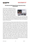
Rear Panel
720W: PSW 30-72, 80-27, 160-14.4
Sense+
terminal
Analog control
connector
USB B
port
Output
terminal
(+)
Chassis
ground
Senseterminal
SER.NO. LABEL
Output
terminal (-)
Fan
LAN
LAN
AC
100
47 63Hz
1080W: PSW 30-108, 80-40.5, 160-21.6
240V
1000VA MAX.
AC Input
360W: PSW 30-36,
80-13.5, 160-7.2
AC Input
SER.NO. LABEL
LAN
N
AC 100
47 63Hz
L
AC 100
47 63Hz
240V
500VA MAX.
240V
1500VA MAX.
LAN
17
PSW Series Programming Manual
720W: PSW 250-9, 800-2.88
Sense+
terminal
Analog control
connector
USB B
port
Output
terminals +V
Senseterminal
V
SN.C. S
V
SER.NO. LABEL
Chassis
ground
Output
terminals -V
Fan
LAN
LAN
AC 100 240V
47 63Hz 1000VA MAX.
AC Input
1080W: PSW 250-13.5, 800-4.32
360W: PSW 250-4.5,
800-1.44
AC Input
V
SN.C. S
LAN
V
SER.NO. LABEL
N
V
SN.C. S
V
AC 100 240V
47 63Hz 500VA MAX.
L
AC 100 240V
47 63Hz 1500VA MAX.
LAN
18
GETTING STARTED
Standard 26 pin MIL connector
(OMRON XG4 IDC plug).
Analog Control
Connector
The analog control connector is
used to monitor current and voltage
output, machine status (OVP, OCP,
OTP etc.), and for analog control of
the current and voltage output.
Use an OMRON XG5 IDC socket as
the mating socket.
Positive (+) and negative (-) output
terminals.
Output Terminals
(30, 80, 160 volt
models)
Chassis ground
Sense (-S) and Sense (+S) terminals.
Output Terminals The 250 and 800 volt models use a 9 pin connector
(250, 800 volt
and a plug for the output and sense terminal
models)
connections. The plug is a MC420-38109Z plug by
DECA SwitchLab Inc. This plug is also available
separately (GW part number 39BT-50900401).
V
SN.C. S
V
V
SN.C. S
SN.C. S
Positive (V+) and negative (V-)
output terminals (3 of each).
V
V
V
Chassis ground
Sense (-S) and Sense (+S)
terminals.
19
PSW Series Programming Manual
USB B port
The USB B port is used for remote
control.
Fans
Temperature controlled fans
Ethernet Port
The ethernet port is used for remote
control and digital monitoring from
a PC.
LAN
Line Voltage
Input
Type I: PSW 30-36/80-13.5/
160-7.2/250-4.5, 800-1.44
(Type I/TypeII)
Type II: PSW 30-72/80-27/
160-14.4/250-9, 800-2.88
Voltage Input: 100~240 VAC
Line frequency: 50Hz/60 Hz
(Automatically switchable)
Line Voltage
Input
(Type III)
20
N
L
Type III:
PSW 30-108/80-40.5/160-21.6/
250-13.5/800-4.32
Voltage Input: 100~240 VAC
Line frequency: 50Hz/60 Hz
(Automatically switchable)
GETTING STARTED
Configuration Settings
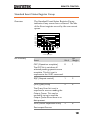
Configuration of the PSW power supplies is divided into five
different configuration settings: Normal Function, USB/GPIB, LAN,
Power ON Configuration, Calibration Settings and System Settings.
Power ON Configuration differs from the other settings in that the
settings used with Power ON Configuration settings can only be set
during power up. The other configuration settings can be changed
when the unit is already on. This prevents some important
configuration parameters from being changed inadvertently. Power
On Configuration settings are numbered F-90 to F-95 and the other
configuration settings are numbered F-00 to F-61 and F-88 to F-89.
Setting Normal Function Settings
The normal function settings (F-01~F-61, F-88~F89) can be easily configured with the Function key.
Note
Ensure the load is not connected.
Ensure the output is off.
Function setting F-89 (Show Version) can only be
viewed, not edited.
Configuration settings F-90~F-95 cannot be edited
in the Normal Function Settings. Use the Power
On Configuration Settings. See page 22 for details.
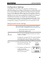
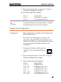
Steps
1. Press the Function key. The
function key will light up.
Function
2. The display will show F-01
on the top and the
configuration setting for
F-01 on the bottom.
21
PSW Series Programming Manual
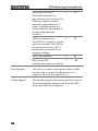
3. Rotate the voltage knob to change
the F setting.
Range
F-00~ F-61, F-88~F-89
4. Use the current knob to set the
parameter for the chosen F setting.
5. Press the Voltage knob to save the
configuration setting. ConF will be
displayed when successful.
Exit
Voltage
Press the Function key again to exit
the configuration settings. The
function key light will turn off.
Current
Voltage
Function
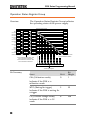
Setting Power On Configuration Settings
Background
The Power On configuration settings can only be
changed during power up to prevent the
configuration settings being inadvertently
changed.
22
Ensure the load is not connected.
Ensure the power supply is off.
GETTING STARTED
Steps
6. Hold the Function key whilst
turning the power on.
7. The display will show F-90 on the
top and the configuration setting
for F-90 on the bottom.
8. Rotate the voltage knob to change
the F setting.
Range
Multi-Range DC Power Supply
360W
VSR
Voltage
W
CV
V
RMT
ALM
20
40
60
80
100
%W
DLY
Current
W
CC
A
ISR
Function
OVP/OCP
Set
Test
Lock/Local
PWR DSPL
Output
Voltage
F-90~ F-95
9. Use the current knob to set the
parameter for the chosen F setting.
10. Press the Voltage knob to save the
configuration setting. ConF will be
displayed when successful.
Exit
PSW 30-36
Current
Voltage
Cycle the power to save and exit the configuration
settings.
23
PSW Series Programming Manual
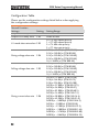
Configuration Table
Please use the configuration settings listed below when applying
the configuration settings.
Normal Function
Settings
Output ON delay time
Output OFF delay time
Setting
F-01
F-02
V-I mode slew rate select F-03
Rising voltage slew rate
F-04
Falling voltage slew rate F-05
Rising current slew rate
24
F-06
Setting Range
0.00s~99.99s
0.00s~99.99s
0 = CV high speed priority
1 = CC high speed priority
2 = CV slew rate priority
3 = CC slew rate priority
0.01V/s~60.00V/s (PSW 30-XX)
0.1V/s~160.0V/s (PSW 80-XX)
0.1V/s~320.0V/s (PSW 160-XX)
0.1V/s~500.0V/s (PSW 250-XX)
1V/s~1600V/s (PSW 800-XX)
0.01V/s~60.00V/s (PSW 30-XX)
0.1V/s~160.0V/s (PSW 80-XX)
0.1V/s~320.0V/s (PSW 160-XX)
0.1V/s~500.0V/s (PSW 250-XX)
1V/s~1600V/s (PSW 800-XX)
0.01A/s~72.00A/s (PSW 30-36)
0.1A/s~144.0A/s (PSW 30-72)
0.1A/s~216.0A/s (PSW 30-108)
0.01A/s~27.00A/s (PSW 80-13.5)
0.01A/s~54.00A/s (PSW 80-27)
0.01A/s~81.00A/s (PSW 80-40.5)
0.01A/s~14.40A/s (PSW 160-7.2)
0.01A/s~28.80A/s (PSW 160-14.4)
0.01A/s~43.20A/s (PSW 160-21.6)
0.001A/s ~ 9.000A/s (PSW 250-4.5)
0.01A/s ~ 18.00A/s (PSW 250-9)
0.01A/s ~ 27.00A/s (PSW 250-13.5)
0.001A/s ~ 2.880A/s (PSW 800-1.44)
0.001A/s ~ 5.760A/s (PSW 800-2.88)
0.001A/s ~ 8.640A/s (PSW 800-4.32)
GETTING STARTED
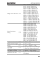
Falling current slew rate F-07
Internal resistance
setting
F-08
Bleeder circuit control
F-09
Buzzer ON/OFF control F-10
Measurement Average
F-17
Setting
Lock Mode
F-19
USB/GPIB settings
Front panel USB State
F-20
Rear panel USB State
F-21
0.01A/s~72.00A/s (PSW 30-36)
0.1A/s~144.0A/s (PSW 30-72)
0.1A/s~216.0A/s (PSW 30-108)
0.01A/s~27.00A/s (PSW 80-13.5)
0.01A/s~54.00A/s (PSW 80-27)
0.01A/s~81.00A/s (PSW 80-40.5)
0.01A/s~14.40A/s (PSW 160-7.2)
0.01A/s~28.80A/s (PSW 160-14.4)
0.01A/s~43.20A/s (PSW 160-21.6)
0.001A/s ~ 9.000A/s (PSW 250-4.5)
0.01A/s ~ 18.00A/s (PSW 250-9)
0.01A/s ~ 27.00A/s (PSW 250-13.5)
0.001A/s ~ 2.880A/s (PSW 800-1.44)
0.001A/s ~ 5.760A/s (PSW 800-2.88)
0.001A/s ~ 8.640A/s (PSW 800-4.32)
0.000Ω~0.833Ω (PSW 30-36)
0.000Ω~0.417Ω (PSW 30-72)
0.000Ω~0.278Ω (PSW 30-108)
0.000Ω~5.926Ω (PSW 80-13.5)
0.000Ω~2.963Ω (PSW 80-27)
0.000Ω~1.975Ω (PSW 80-40.5)
0.000Ω~22.222Ω (PSW 160-7.2)
0.000Ω~11.111Ω (PSW 160-14.4)
0.000Ω~7.407Ω (PSW 160-21.6)
0.00Ω ~ 55.55Ω (PSW 250-4.5)
0.00Ω ~ 27.77Ω (PSW 250-9)
0.00Ω ~ 18.51Ω (PSW 250-13.5)
0.0Ω ~ 555.5Ω (PSW 800-1.44)
0.0Ω ~ 277.8Ω (PSW 800-2.88)
0.0Ω ~ 185.1Ω (PSW 800-4.32)
0 = OFF, 1 = ON
0 = OFF, 1 = ON
0 = Low, 1 = Middle, 2 = High
0 = Panel lock: allow output off
1 = Panel lock: allow output on/off
0 = Absent, 1 = Mass Storage
0 = Absent, 2 = USB-CDC, 3 = GPIBUSB adapter
25
PSW Series Programming Manual
Rear panel USB mode
F-22
GPIB address
LAN settings
MAC Address-1
MAC Address-2
MAC Address-3
MAC Address-4
MAC Address-5
MAC Address-6
LAN
DHCP
IP Address-1
IP Address-2
IP Address-3
IP Address-4
Subnet Mask-1
Subnet Mask-2
Subnet Mask-3
Subnet Mask-4
Gateway-1
Gateway-2
Gateway-3
Gateway-4
DNS address -1
DNS address -2
DNS address-3
DNS address-4
Sockets active
Web Server active
Web password active
Web setting password
System Settings
F-23
0 = Disable, 1 = GPIB-USB adapter,
2 = Auto detect speed, 3 = Full speed
only
0~30
F-30
F-31
F-32
F-33
F-34
F-35
F-36
F-37
F-39
F-40
F-41
F-42
F-43
F-44
F-45
F-46
F-47
F-48
F-49
F-50
F-51
F-52
F-53
F-54
F-57
F-59
F-60
F-61
0x00~0xFF
0x00~0xFF
0x00~0xFF
0x00~0xFF
0x00~0xFF
0x00~0xFF
0 = Disable, 1 = Enable
0 = Disable, 1 = Enable
0~255
0~255
0~255
0~255
0~255
0~255
0~255
0~255
0~255
0~255
0~255
0~255
0~255
0~255
0~255
0~255
0 = Disable, 1 = Enable
0 = Disable, 1 = Enable
0 = Disable, 1 = Enable
0000~9999
Factory Set Value
F-88
0 = Disable
1 = Return to factory settings
26
GETTING STARTED
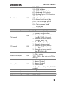
Show Version
F-89
0, 1 = PSW version
2, 3 = PSW build year
4, 5 = PSW build month/day
6, 7 = Keyboard CPLD version
8, 9 = Analog-Control CPLD version
A, B = Reserved
C, D = Kernel build year
E, F = Kernel build month/day
G, H = Test command version
I, J = Test command build year
K, L = Test command build
month/day
M, N = USB Driver version.
Power On Configuration Settings*
CC Control
F-91
Power-ON Output
F-92
Master/Slave
F-93
External Out Logic
Power Switch trip
Calibration Settings*
Calibration
F-94
F-95
0 = Panel control (local)
1 = External voltage control
2 = External resistance control
(Ext-R 10kΩ = Vo, max)
3 = External resistance control
(Ext-R 10kΩ = 0)
0 = Panel control (local)
1 = External voltage control
2 = External resistance control
(Ext-R 10kΩ = Io,max)
3 = External resistance control
(Ext-R 10kΩ = 0)
0 = OFF at startup
1 = ON at startup
T001 ~ T010 = Run test script TXX at
start up
0 = Master/Local
1 = Master/Parallel1
2 = Master/Parallel2
3 = Slave/Parallel
4 = Slave/Series (Only 30V, 80V, 160V
models)
0 = High ON, 1 = Low ON
0 = Enable , 1 = Disable
F-00
0000 ~ 9999
CV Control
F-90
27
PSW Series Programming Manual
*Note
28
Power On and Calibration settings can only be set
during power up.
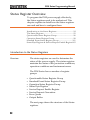
REMOTE CONTROL
REMOTE CONTROL
This chapter describes basic configuration of
IEEE488.2 based remote control. For a command
list, refer to the programming manual,
downloadable from GW Instek website,
www.gwinstek.com
Interface Configuration ................................................... 30
Socket Server Examples ................................................... 45
Command Syntax ............................................................ 49
Command List ................................................................. 52
Status Register Overview ................................................. 94
Error List ........................................................................ 105
29
PSW Series Programming Manual
Interface Configuration
USB Remote Interface .......................................................... 30
Configure GPIB Interface .................................................... 31
Configure Ethernet Connection .......................................... 32
USB Remote Control Function Check ............................... 34
Using Realterm to Establish a Remote Connection ......... 35
Web Server Remote Control Function Check ................... 39
Socket Server Function Check ............................................. 39
USB Remote Interface
USB
configuration
Panel operation
PC side
connector
Type A, host
PSW side
connector
Rear panel Type B, slave
Speed
1.1/2.0 (full speed/high speed)
USB Class
CDC (communications device
class)
1. Connect the USB cable to the rear
panel USB B port.
2. Press the Function key to enter the Page 21
Normal configuration settings.
Set the following USB settings:
Set the rear panel USB port to
F-22 = 2
USB-CDC.
30
REMOTE CONTROL
Configure GPIB Interface
To use GPIB, the optional GPIB to USB (GUG-001) adapter must be
used. The GPIB to USB adapter must be connected before the PSW
is turned on. Only one GPIB address can be used at a time.
Configure GPIB
1. Ensure the PSW is off before proceeding.
2. Connect the USB cable from the rear panel
USB B port on the PSW to the USB A port on
the GPIB to USB adapter.
3. Connect a GPIB cable from a GPIB controller to
the GPIB port on the adapter.
Type A plug
From
computer
Type B plug for
PSW series
GUG-001
4. Turn the PSW on.
5. Press the Function key to enter the Page 21
Normal configuration settings.
Set the following GPIB settings:
Set the rear panel USB port to
F-22 = 1
GPIB-USB (GUG-001)
F-23 = 0~30
Set the GPIB address (0~30)
GPIB constraints
Maximum 15 devices altogether, 20m cable
length, 2m between each device
Unique address assigned to each device
At least 2/3 of the devices turned On
No loop or parallel connection
31
PSW Series Programming Manual
Configure Ethernet Connection
The Ethernet interface can be configured for a number of different
applications. Ethernet can be configured for basic remote control or
monitoring using a web server or it can be configured as a socket
server.
The PSW series supports both DHCP connections so the instrument
can be automatically connected to an existing network or
alternatively, network settings can be manually configured.
Ethernet
configuration
Parameters
For details on how to configure the Ethernet
settings, please see the configuration table on
page 24.
MAC Address
(display only)
LAN
DHCP
IP Address
Subnet Mask
Gateway
DNS Address
Sockets Active
Web Server Active
Web Password Active
Web set password
0000~9999 (default 0000)
Web Server Configuration
Configuration
This configuration example will configure the
PSW as a web server and use DHCP to
automatically assign an IP address to the PSW.
1. Connect an Ethernet cable from the
network to the rear panel Ethernet
port.
32
LAN
REMOTE CONTROL
2. Press the Function key to enter the Page 21
Normal configuration settings.
Set the following LAN settings:
F-36 = 1
F-37 = 1
F-59 = 1
Note
Enable LAN
Turn DHCP to enable
Turn the web server on
It may be necessary to cycle the power or refresh
the web browser to connect to a network.
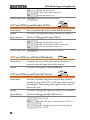
Sockets Server Configuration
Configuration
This configuration example will configure the
PSW sockets server.
The following configuration settings will
manually assign the PSW an IP address and
enable the socket server. By default, the socket
server port number is 2268 and cannot be
configured.
1. Connect an Ethernet cable from the
network to the rear panel Ethernet
port.
LAN
2. Press the Function key to enter the Page 21
Normal configuration settings.
3. Set the following LAN settings:
F-36 = 1
Enable LAN
F-37 = 0
Disable DHCP
F-39 = 172
IP Address part 1 of 4
F-40 = 16
IP Address part 2 of 4
F-41 = 5
IP Address part 3 of 4
F-42 = 133
IP Address part 4 of 4
F-43 = 255
Subnet Mask part 1 of 4
33
PSW Series Programming Manual
F-44 = 255
F-45 = 128
F-46 = 0
F-43 = 172
F-44 = 16
F-45 = 21
F-46 = 101
F-57 = 1
Note
Subnet Mask part 2 of 4
Subnet Mask part 3 of 4
Subnet Mask part 4 of 4
Gateway part 1 of 4
Gateway part 2 of 4
Gateway part 3 of 4
Gateway part 4 of 4
Enable Sockets
The socket function is only available for firmware
version V1.12 or above. See the user manual to
check your firmware version number.
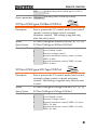
USB Remote Control Function Check
Functionality
check
Invoke a terminal application such as Realterm.
The PSW will appear as a COM port on the PC.
To check the COM port No, see the Device
Manager in the PC. For WinXP; Control panel
→ System → Hardware tab.
Note
If you are not familiar with using a terminal
application to send/receive remote commands via
a USB connection, please page 35(Using Realterm
to Establish a Remote Connection) for more
information.
Run this query command via the terminal after
the instrument has been configured for USB
remote control (page 30).
*idn?
This should return the Manufacturer, Model
number, Serial number, and Firmware version
in the following format.
GW-INSTEK,PSW-XXX-X,TW123456,01.00.20110101
34
REMOTE CONTROL
Manufacturer: GW-INSTEK
Model number : PSW-3036
Serial number : TW123456
Firmware version : 01.00.20110101
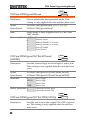
Using Realterm to Establish a Remote Connection
Background
Realterm is a terminal program that can be
used to communicate with a device attached to
the serial port of a PC or via an emulated serial
port via USB.
The following instructions apply to version
2.0.0.70. Even though Realterm is used as an
example to establish a remote connection, any
terminal program can be used that has similar
functionality.
Note
Realterm can be downloaded on Sourceforge.net
free of charge.
For more information please see
http://realterm.sourceforge.net/
Operation
1. Download Realterm and install according to the
instructions on the Realterm website.
2. Connect the PSW via USB (page 30).
3. Go to the Windows device manager and find
the COM port number for the connection.
For example, go to the Start menu > Control
Panel > Device Manager
Double click the Ports icon to reveal the
connected serial port devices and the COM port
for the each connected device.
35
PSW Series Programming Manual
The baud rate, stop bit and parity settings can
be viewed for the virtual COM port by rightclicking connected device and selecting the
Properties option.
4. Start Realterm on the PC as an administrator.
Click:
Start menu>All Programs>RealTerm>realterm
Tip: to run as an administrator, you can right
click the Realterm icon in the Windows Start
menu and select the Run as Administrator
option.
36
REMOTE CONTROL
5. After Realterm has started, click on the Port tab.
Enter the Baud, Parity, Data bits, Stop bits and
Port number configuration for the connection.
The Hardware Flow Control, Software Flow
Control options can be left at the default
settings.
Press Open to connect to the PSW.
37
PSW Series Programming Manual
6. Click on the Send tab.
In the EOL configuration, check on the +CR and
+LF check boxes.
Enter the query:
*idn?
Click on Send ASCII.
7. The terminal display will return the following:
GW-INSTEK,PSW-XXX-X,TW123456,01.00.20110101
(manufacturer, model, serial number, version)
8. If Realterm fails to connect to the PSW, please
check all the cables and settings and try again.
38
REMOTE CONTROL
Web Server Remote Control Function Check
Functionality
check
Enter the IP address of the power supply in a
web browser after the instrument has been
configured as a web server (page 32).
http:// XXX.XXX.XXX.XXX
The web browser interface appears.
Socket Server Function Check
Background
To test the socket server functionality, National
Instruments Measurement and Automation
Explorer can be used. This program is available
on the NI website, www.ni.com, via a search
for the VISA Run-time Engine page, or
“downloads” at the following URL,
http://www.ni.com/visa/
Requirements
Firmware: V1.12
Operating System: Windows XP, 7
Functionality
check
1. Start the NI Measurement and Automation
Explorer (MAX) program. Using Windows,
press:
Start>All Programs>National
Instruments>Measurement & Automation
39
PSW Series Programming Manual
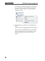
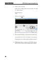
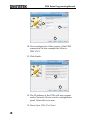
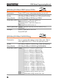
2. From the Configuration panel access;
My System>Devices and Interfaces>Network
Devices
3. Click Create New... .
4. Select Visa TCP/IP Resource.
3
2
4
40
REMOTE CONTROL
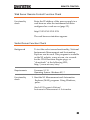
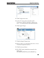
5. Select Manual Entry of Raw Socket from the
popup window.
6. Click Next.
5
6
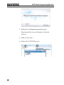
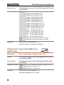
7. Enter the IP address and the port number of the
PSW. The port number is fixed at 2268.
8. Click the Validate button. A popup box will
appear when successful.
9. Click Next.
41
PSW Series Programming Manual
7
8
9
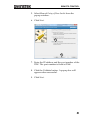
10. Next configure the Alias (name) of the PSW
connection. In this example the Alias is:
PSW_DC1
11. Click finish.
10
11
12. The IP address of the PSW will now appear
under Network Devices in the configuration
panel. Select this icon now.
13. Press Open VISA Test Panel.
42
REMOTE CONTROL
13
12
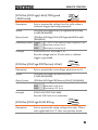
14. Click Configuration icon.
15. In the I/O Settings tab, select the Enable
Termination Character check box. Ensure Line
Feed - \n is selected as the line feed character.
16. Click Apply Changes.
14
15
16
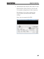
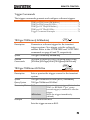
17. Click the Input/Output icon.
18. Ensure *IDN?\n is selected in the Select or Enter
Command dropdown text box.
19. Click the Query button.
20. The *IDN? query should be returned to the
buffer area:
GW-INSTEK,PSW250-9,,01.54.20140313\n
43
PSW Series Programming Manual
17
18
19
20
Note
44
For further details, please see the following
programming examples.
REMOTE CONTROL
Socket Server Examples
Visual Basic Example ............................................................ 45
C++ Example ........................................................................ 46
LabVIEW Example ............................................................... 48
Visual Basic Example
Background
The following visual basic programming
example uses the VISA COM 3.0 Type Library.
The example will connect to the PSW using the
IP address of 172.15.5.133 over port 2268. The
program will send the *IDN? to the PSW, print
the return string and then close the connection.
45
PSW Series Programming Manual
C++ Example
Background
Note
46
The following program creates a connection to
the PSW and sets the voltage to 3.3 volts and
the current 1.5 amps. The voltage and current
reading is then read back and the connection is
closed.
Add visa32.lib to the project library when
building the following sample program.
REMOTE CONTROL
47
PSW Series Programming Manual
LabVIEW Example
Background
48
The following picture shows a LabView
programming example for the PSW.
REMOTE CONTROL
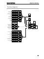
Command Syntax
Compatible
Standard
Command
Structure
IEEE488.2
Partial compatibility
SCPI, 1999
Partial compatibility
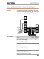
SCPI commands follow a tree-like structure,
organized into nodes. Each level of the
command tree is a node. Each keyword in a
SCPI command represents each node in the
command tree. Each keyword (node) of a SCPI
command is separated by a colon (:).
For example, the diagram below shows an SCPI
sub-structure and a command example.
MEASure
MEASure:SCALar:CURRent:DC?
SCALar
Command types
VOLTage
CURRent
POWer
DC
DC
DC
There are a number of different instrument
commands and queries. A command sends
instructions or data to the unit and a query
receives data or status information from the
unit.
Command types
Simple
A single command
with/without a parameter
Example
*IDN?
49
PSW Series Programming Manual
Query
A query is a simple or
compound command
followed by a question mark
(?). A parameter (data) is
returned.
Example
meas:curr:dc?
Compound
Two or more commands on
the same command line.
Compound commands are
separated with either a semicolon (;) or a semi-colon and a
colon (;:).
A semi-colon is used to join
two related commands, with
the caveat that the last
command must begin at the
last node of the first
command.
A semi-colon and colon are
used to combine two
commands from different
nodes.
Example
50
meas:volt:dc?;:meas:curr:dc?
REMOTE CONTROL
Command Forms
Commands and queries have two different
forms, long and short. The command syntax is
written with the short form of the command in
capitals and the remainder (long form) in lower
case.
The commands can be written in capitals or
lower-case, just so long as the short or long
forms are complete. An incomplete command
will not be recognized.
Below are examples of correctly written
commands.
STATus:OPERation:NTRansition?
Long
form
STATUS:OPERATION:NTRANSITION?
status:operation:ntransition?
STAT:OPER:NTR?
Short
form
stat:oper:ntr?
Square Brackets
Commands that contain square brackets
indicate that the contents are optional. The
function of the command is the same with or
without the square bracketed items, as shown
below.
Both “DISPlay:MENU[:NAME]?” and
“DISPlay:MENU?” are both valid forms.
Command
Format
APPLY
1
1.5,5.2
2 34 5
1.
2.
3.
4.
5.
Parameters
Command header
Space
Parameter 1
Comma (no space
before/after comma)
Parameter 2
Type
Description
Example
<Boolean>
Boolean logic
0, 1
51
PSW Series Programming Manual
<NR1>
integers
0, 1, 2, 3
<NR2>
decimal
numbers
0.1, 3.14, 8.5
<NR3>
floating point
4.5e-1, 8.25e+1
<NRf>
any of NR1, 2, 3 1, 1.5, 4.5e-1
<block data> Definitive length arbitrary block
data. A single decimal digit
followed by data. The decimal
digit specifies how many 8-bit
data bytes follow.
Message
Terminator
LF
Line feed code
Command List
Abort Commands ABORt .................................................................................... 55
Apply Commands APPLy ..................................................................................... 55
Display
Commands
DISPlay:MENU[:NAME] .................................................... 56
DISPlay[:WINDow]:TEXT:CLEar..................................... 57
DISPlay[:WINDow]:TEXT[:DATA].................................. 57
DISPlay:BLINk ...................................................................... 57
Initiate
Commands
INITiate[:IMMediate]:NAME ............................................. 58
Measure
Commands
MEASure[:SCALar]:CURRent[:DC] ................................... 59
MEASure[:SCALar]:VOLTage[:DC] .................................. 59
MEASure[:SCALar]:POWer[:DC] ....................................... 59
Output
Commands
OUTPut:DELay:ON ............................................................ 60
OUTPut:DELay:OFF ........................................................... 60
OUTPut:MODE ................................................................... 61
52
REMOTE CONTROL
OUTPut[:STATe][:IMMediate] ........................................... 61
OUTPut[:STATe]:TRIGgered ............................................. 61
OUTPut:PROTection:CLEar .............................................. 62
OUTPut:PROTection:TRIPped .......................................... 62
Sense
Commands
SENSe:AVERage:COUNt ................................................... 63
Status
Commands
STATus:OPERation[:EVENt] ............................................ 64
STATus:OPERation:CONDition ....................................... 64
STATus:OPERation:ENABle ............................................. 64
STATus:OPERation:PTRansition ....................................... 65
STATus:OPERation:NTRansition ...................................... 65
STATus:QUEStionable[:EVENt] ....................................... 65
STATus:QUEStionable:CONDition .................................. 66
STATus:QUEStionable:ENABle ........................................ 66
STATus:QUEStionable:PTRansition.................................. 66
STATus:QUEStionable:NTRansition ................................. 66
STATus:PRESet..................................................................... 67
Source
Commands
[SOURce:]CURRent[:LEVel][:IMMediate][:AMPLitude] 68
[SOURce:]CURRent[:LEVel]:TRIGgered[:AMPLitude].. 69
[SOURce:]CURRent:PROTection[:LEVel] ....................... 69
[SOURce:]CURRent:PROTection:STATe ......................... 70
[SOURce:]CURRent:SLEW:RISing .................................... 70
[SOURce:]CURRent:SLEW:FALLing ................................ 71
[SOURce:]RESistance[:LEVel][:IMMediate]
[:AMPLitude] .......................................................................... 71
[SOURce:]VOLTage[:LEVel][:IMMediate]
[:AMPLitude] .......................................................................... 72
[SOURce:]VOLTage[:LEVel]:TRIGgered[:AMPLitude] . 73
[SOURce:]VOLTage:PROTection[:LEVel] ....................... 73
[SOURce:]VOLTage:SLEW:RISing .................................... 73
[SOURce:]VOLTage:SLEW:FALLing ............................... 74
Trigger
Commands
TRIGger:TRANsient[:IMMediate] ...................................... 75
TRIGger:TRANsient:SOURce ............................................ 75
TRIGger:OUTPut[:IMMediate] .......................................... 76
TRIGger:OUTPut:SOURce ................................................. 76
Trigger Command Examples ............................................... 76
53
PSW Series Programming Manual
System
Commands
SYSTem:BEEPer[:IMMediate] ............................................ 79
SYSTem:CONFigure:BEEPer[:STATe] ............................. 79
SYSTem:CONFigure:BLEeder[:STATe] ........................... 80
SYSTem:CONFigure:BTRip[:IMMediate] ......................... 80
SYSTem:CONFigure:BTRip:PROTection ........................ 80
SYSTem:CONFigure:CURRent:CONTrol ........................ 81
SYSTem:CONFigure:VOLTage:CONTrol ....................... 81
SYSTem:CONFigure:MSLave ............................................. 82
SYSTem:CONFigure:OUTPut:EXTernal[:MODE] ........ 82
SYSTem:CONFigure:OUTPut:PON[:STATe] ................. 82
SYSTem:COMMunicate:ENABle ....................................... 83
SYSTem:COMMunicate:GPIB[:SELF]:ADDRess ........... 84
SYSTem:COMMunicate:LAN:IPADdress ........................ 84
SYSTem:COMMunicate:LAN:GATEway ......................... 84
SYSTem:COMMunicate:LAN:SMASk ............................... 85
SYSTem:COMMunicate:LAN:MAC .................................. 85
SYSTem:COMMunicate:LAN:DHCP................................ 85
SYSTem:COMMunicate:LAN:DNS ................................... 86
SYSTem:COMMunicate:LAN:HOSTname....................... 86
SYSTem:COMMunicate:LAN:WEB:PACTive ................. 86
SYSTem:COMMunicate:LAN:WEB:PASSword ................... 87
SYSTem:COMMunicate:USB:FRONt:STATe.................. 87
SYSTem:COMMunicate:USB:REAR:STATe .................... 87
SYSTem:COMMunicate:USB:REAR:MODE................... 87
SYSTem:ERRor ..................................................................... 88
SYSTem:KEYLock:MODE................................................. 88
SYSTem:KLOCk ................................................................... 88
SYSTem:INFormation .......................................................... 89
SYSTem:PRESet .................................................................... 89
SYSTem:VERSion ................................................................. 89
Common
Commands
*CLS ........................................................................................ 90
*ESE ........................................................................................ 90
*ESR ........................................................................................ 90
*IDN ....................................................................................... 91
*OPC ....................................................................................... 91
*RST ........................................................................................ 91
*SRE ........................................................................................ 92
*STB ........................................................................................ 92
*TRG ....................................................................................... 92
*TST ........................................................................................ 92
*WAI ....................................................................................... 93
54
REMOTE CONTROL
Abort Commands
ABORt .................................................................................... 55
ABORt
Set
Description
The ABORt command will cancel any triggered
actions.
Syntax
ABORt
APPLy Commands
APPLy ..................................................................................... 55
Set
APPLy
Description
Query
The APPLy command is used to set both the
voltage and current. The voltage and current will
be output as soon as the function is executed if the
programmed values are within the accepted range.
An execution error will occur if the programmed
values are not within accepted ranges.
The Apply command will set the voltage/current
values but these values will not be reflected on the
display until the Output is On or if the
DISPlay:MENU:NAME 3 (set menu) command is
used.
Syntax
APPLy {<voltage>|MIN|MAX}[,{<current>|MIN|MAX}]
Query Syntax
APPLy?
55
PSW Series Programming Manual
Parameter
<voltage>
<current>
MIN
MAX
Return parameter <NRf>
Example
<NRf> 0% ~ 105% of the rated output
voltage.
<NRf> 0% ~ 105% of the rated output
current.
0 volts/0 amps
Maxium value for the present range.
Returns the voltage and current.
APPL 5.05,1.1
Sets the voltage and current to 5.05V and 1.1A.
Query Example
APPL?
+5.050, +1.100
Returns voltage (5.05V) and current (1.1A) setting.
Display Commands
DISPlay:MENU[:NAME] .................................................... 56
DISPlay[:WINDow]:TEXT:CLEar..................................... 57
DISPlay[:WINDow]:TEXT[:DATA].................................. 57
DISPlay:BLINk ...................................................................... 57
Set
DISPlay:MENU[:NAME]
Query
Description
The DISPlay MENU command selects a screen
menu or queries the current screen menu.
Syntax
DISPlay:MENU[:NAME] <NR1>
Query Sytax
DISPlay:MENU[:NAME]?
Parameter/
<NR1> Description
Measurement-Voltage / MeasurementReturn parameter 0
1
2
3
4
5~99
100~199
56
Current
Measurement-Voltage / Measurement-Power
Measurement-Power / Measurement-Current
Set Menu
OVP / OCP Menu
Not Used.
F-00~99 Menu.
REMOTE CONTROL
Example
DISP:MENU:NAME 0
Sets the display to the Voltage/Current display screen.
DISPlay[:WINDow]:TEXT:CLEar
Set
Description
Clears the text on the main screen from the
DISPlay[:WINDow]:TEXT[:DATA] command .
Syntax
DISPlay[:WINDow]:TEXT:CLEar
Set
DISPlay[:WINDow]:TEXT[:DATA]
Query
Description
Sets or queries the data text that will be written to
the display. Writing to the display will overwrite
data that is currently on the screen. Overwriting a
display area with a shorter string may or may not
overwrite the screen. The string must be enclosed
in quotes: “STRING”. Only ASCII characters 20H
to 7EH can be used in the <string>.
Syntax
DISPlay[:WINDow]:TEXT[:DATA] <string>
Query Syntax
DISPlay[:WINDow]:TEXT[:DATA]?
Parameter/
<string> ASCII character 20H to 7EH can be used to in
the string parameter. The string must be
Return parameter
enclosed in quotes: “STRING”
Example
DISP:WIND:TEXT:DATA “STRING”
Writes STRING to the display.
Query Example
DISP:WIND:TEXT:DATA?
“STRING”
Returns the text data string on the screen.
Set
DISPlay:BLINk
Query
Description
Turns blink on or off for the display.
Syntax
DISPlay:BLINk { 0 | 1 | OFF | ON }
Query Syntax
DISPlay:BLINk?
57
PSW Series Programming Manual
Parameter
0
OFF
1
ON
Return parameter 0
1
Example
<NR1>Turns blink OFF
Turns blink OFF
<NR1> Turns blink ON
Turns blink ON
<NR1>Turns blink OFF
<NR1>Turns blink ON
DISP:BLIN 1
Turns blink ON.
Initiate Commands
INITiate[:IMMediate]:NAME ............................................. 58
INITiate[:IMMediate]:NAME
Description
Set
The INITiate command starts the TRANsient or
OUTPut trigger.
See the trigger commands on page 75 for usage
details.
Syntax
Parameter
INITiate[:IMMediate]:NAME {TRANsient|OUTPut}
TRANSient Starts the TRANsient trigger.
Starts the OUTPut trigger.
OUTPut
Example
INITiate:NAME TRANient
Starts the TRANSient trigger.
58
REMOTE CONTROL
Measure Commands
MEASure[:SCALar]:CURRent[:DC] ................................... 59
MEASure[:SCALar]:VOLTage[:DC] .................................. 59
MEASure[:SCALar]:POWer[:DC] ....................................... 59
MEASure[:SCALar]:CURRent[:DC]
Description
Query
Takes a measurement and returns the average
output current
Syntax
MEASure[:SCALar]:CURRent[:DC]?
Return parameter <NRf> Returns the current in amps.
MEASure[:SCALar]:VOLTage[:DC]
Query
Description
Takes a measurement and returns the average
output voltage.
Syntax
Return
MEASure[:SCALar]:VOLTage[:DC]?
<NRf> Returns the voltage in volts.
MEASure[:SCALar]:POWer[:DC]
Query
Description
Takes a measurement and returns the average
output power.
Syntax
Return
MEASure[:SCALar]:POWer[:DC]?
<NRf> Returns the power measured in watts.
59
PSW Series Programming Manual
Output Commands
OUTPut:DELay:ON ............................................................ 60
OUTPut:DELay:OFF ........................................................... 60
OUTPut:MODE ................................................................... 61
OUTPut[:STATe][:IMMediate] ........................................... 61
OUTPut[:STATe]:TRIGgered ............................................. 61
OUTPut:PROTection:CLEar .............................................. 62
OUTPut:PROTection:TRIPped .......................................... 62
Set
OUTPut:DELay:ON
Query
Description
Sets the Delay Time in seconds for turning the
output on. The delay is set to 0.00 by default.
Syntax
OUTPut:DELay:ON <NRf>
Query Syntax
Parameter
OUTPut:DELay:ON?
<NRf> 0.00~99.99 seconds, where 0=no delay.
Return parameter <NRf>
Returns the delay on time in seconds until the
output is turned on.
Set
OUTPut:DELay:OFF
Query
Description
Sets the Delay Time in seconds for turning the
output off. The delay is set to 0.00 by default.
Syntax
OUTPut:DELay:OFF <NRf>
Return Syntax
Parameter
OUTPut:DELay:OFF?
<NRf> 0.00~99.99 seconds, where 0=no delay.
Return parameter <NRf>
60
Returns the delay off time in seconds until the
output is turned off.
REMOTE CONTROL
Set
OUTPut:MODE
Query
Description
Sets the PSW output mode. This is the equivalent
to the F-03 (V-I Mode Slew Rate Select) settings.
Syntax
OUTPut:MODE {<NR1>|CVHS|CCHS|CVLS|CCLS}
Return Syntax
Parameter
OUTPut:MODE?
CV high speed priority
0
CV high speed priority
CVHS
CC high speed priority
1
CC high speed priority
CCHS
CV slew rate priority
2
CV slew rate priority
CVLS
CC slew rate priority
3
CC slew rate priority
CCLS
Return parameter <NR1>
Returns the output mode.
Set
OUTPut[:STATe][:IMMediate]
Query
Description
Turns the output on or off.
Syntax
OUTPut[:STATe][:IMMediate] { OFF | ON | 0 | 1 }
Query Syntax
Parameter
OUTPut[:STATe][:IMMediate]?
<NR1> Turns the output off.
0
Turns the output off.
OFF
<NR1> Turns the output on.
1
Turns the output on.
ON
Return parameter <NR1>
Returns output status of the instrument.
Set
OUTPut[:STATe]:TRIGgered
Query
Description
Turns the output on or off when a software trigger
is generated.
Syntax
OUTPut[:STATe]:TRIGgered { OFF | ON | 0 | 1 }
Query Syntax
OUTPut[:STATe]:TRIGgered?
61
PSW Series Programming Manual
Parameter
0
OFF
1
ON
Return parameter <NR1>
<NR1>Turns the output off when a software
trigger is generated.
Turns the output off when a software trigger
is generated.
<NR1>Turns the output on when a software
trigger is generated.
Turns the output on when a software trigger
is generated.
Returns output trigger status of the
instrument.
OUTPut:PROTection:CLEar
Set
Description
Clears over-voltage, over-current and overtemperature (OVP, OCP, OTP) protection circuits.
It also clears the shutdown protection circuit. The
AC failure protection cannot be cleared.
Syntax
OUTPut:PROTection:CLEar
OUTPut:PROTection:TRIPped
Description
Query
Returns the state of the protection circuits (OVP,
OCP, OTP).
Query Syntax
OUTPut:PROTection:TRIPped?
<NR1>Protection circuits are not tripped.
Return parameter 0
<NR1>Protection circuits are tripped.
1
62
REMOTE CONTROL
Sense Commands
SENSe:AVERage:COUNt ................................................... 63
Set
SENSe:AVERage:COUNt
Query
Description
Determines the level of smoothing for the average
setting. This is the equivalent to the F-17 function
setting.
Syntax
SENSe:AVERage:COUNt {<NR1>| LOW | MIDDle |
HIGH}
Query Syntax
Parameter
SENSe:AVERage:COUNt?
Low level of smoothing.
0 | LOW
1 | MIDDle Middle level of smoothing.
High level of smoothing.
2 | HIGH
Returns the level of smoothing.
Return parameter <NR1>
Low level of smoothing.
0
Middle level of smoothing.
1
High level of smoothing.
2
Example
SENSe:AVERage:COUNt 1
Sets the level of smoothing to middle.
63
PSW Series Programming Manual
Status Commands
STATus:OPERation[:EVENt] ............................................ 64
STATus:OPERation:CONDition ....................................... 64
STATus:OPERation:ENABle ............................................. 64
STATus:OPERation:PTRansition....................................... 65
STATus:OPERation:NTRansition ...................................... 65
STATus:QUEStionable[:EVENt] ....................................... 65
STATus:QUEStionable:CONDition .................................. 66
STATus:QUEStionable:ENABle ........................................ 66
STATus:QUEStionable:PTRansition ................................. 66
STATus:QUEStionable:NTRansition................................. 66
STATus:PRESet .................................................................... 67
STATus:OPERation[:EVENt]
Description
Query
Queries the Operation Status Event register and
clears the contents of the register.
Syntax
Return
STATus:OPERation[:EVENt]?
<NR1> Returns the bit sum of the Operation Status
Event register.
STATus:OPERation:CONDition
Query
Description
Queries the Operation Status register. This query
will not clear the register.
Syntax
Return
STATus:OPERation:CONDition?
<NR1> Returns the bit sum of the Operation
Condition register.
Set
STATus:OPERation:ENABle
Description
64
Query
Sets or queries the bit sum of the Operation Status
Enable register.
REMOTE CONTROL
Syntax
STATus:OPERation:ENABle <NRf>
Query Syntax
STATus:OPERation:ENABle?
Parameter
<NRf> 0~32767
Return parameter <NR1> 0~32767
Set
STATus:OPERation:PTRansition
Query
Description
Sets or queries the bit sum of the positive
transition filter of the Operation Status register.
Syntax
STATus:OPERation:PTRansition <NRf>
STATus:OPERation:PTRansition?
Parameter
<NRf> 0~32767
Return parameter <NR1> 0~32767
Set
STATus:OPERation:NTRansition
Query
Description
Sets or queries the bit sum of the negative
transition filter of the Operation Status register.
Syntax
STATus:OPERation:NTRansition <NRf>
Query Syntax
STATus:OPERation:NTRansition?
Parameter
<NRf> 0~32767
Return parameter <NR1> 0~32767
STATus:QUEStionable[:EVENt]
Description
Query
Queries the bit sum of the Questionable Status
Event register. This query will also clear the
contents of the register.
Query Syntax
STATus:QUEStionable[:EVENt]?
Parameter
<NRf> 0~32767
Return parameter <NR1> 0~32767
65
PSW Series Programming Manual
STATus:QUEStionable:CONDition
Description
Query
Queries the status (bit sum) of the Questionable
Status register. This query will not clear the
register.
Query Syntax
STATus:QUEStionable:CONDition?
Parameter
<NRf> 0~32767
Return parameter <NR1> 0~32767
Set
STATus:QUEStionable:ENABle
Query
Description
Sets or queries the bit sum of the Questionable
Status Enable register.
Syntax
STATus:QUEStionable:ENABle <NRf>
Query Syntax
STATus:QUEStionable:ENABle?
Parameter
<NRf> 0~32767
Return parameter <NR1> 0~32767
Set
STATus:QUEStionable:PTRansition
Query
Description
Sets or queries the bit sum of the positive
transition filter of the Questionable Status register.
Syntax
STATus:QUEStionable:PTRansition <NRf>
Return Syntax
STATus:QUEStionable:PTRansition?
Parameter
<NRf> 0~32767
Return parameter <NR1> 0~32767
Set
STATus:QUEStionable:NTRansition
Query
Description
Sets or queries the negative transition filter of the
Questionable Status register.
Syntax
STATus:QUEStionable:NTRansition <NRf>
Query Syntax
STATus:QUEStionable:NTRansition?
66
REMOTE CONTROL
Parameter
<NRf>
Return parameter <NR1>
0~32767
0~32767
STATus:PRESet
Description
Set
This command resets the ENABle register, the
PTRansistion filter and NTRansistion filter on the
Operation Status and Questionable Status
Registers. The registers/filters will be reset to a
default value.
Default Register/Filter Values
Setting
QUEStionable Status Enable
0x0000
QUEStionable Status Positive Transition 0x7FFF
QUEStionable Status Negative Transition 0x0000
Operation Status Enable
0x0000
Operation Status Positive Transition
0x7FFF
Operation Status Negative Transition
0x0000
Summary: The Questionable Status Enable
registers and the Operation Status Enable registers
are both reset to 0.
The Questionable Status and Operation Status
Positive Transition filters are all set high (0x7FFF)
and the Negative Transition filters are all set low
(0x0000). I.e., only positive transitions will be
recognized for the Questionable Status and
Operation Status registers.
Syntax
STATus:PRESet
67
PSW Series Programming Manual
Source Commands
[SOURce:]CURRent[:LEVel][:IMMediate][:AMPLitude] 68
[SOURce:]CURRent[:LEVel]:TRIGgered[:AMPLitude].. 69
[SOURce:]CURRent:PROTection[:LEVel] ....................... 69
[SOURce:]CURRent:PROTection:STATe ......................... 70
[SOURce:]CURRent:SLEW:RISing .................................... 70
[SOURce:]CURRent:SLEW:FALLing ................................ 71
[SOURce:]RESistance[:LEVel][:IMMediate]
[:AMPLitude].......................................................................... 71
[SOURce:]VOLTage[:LEVel][:IMMediate][:AMPLitude] 72
[SOURce:]VOLTage[:LEVel]:TRIGgered[:AMPLitude] . 73
[SOURce:]VOLTage:PROTection[:LEVel] ....................... 73
[SOURce:]VOLTage:SLEW:RISing.................................... 73
[SOURce:]VOLTage:SLEW:FALLing ............................... 74
[SOURce:]CURRent[:LEVel][:IMMediate]
[:AMPLitude]
Set
Query
Description
Sets or queries the current level in amps. For
externally set current levels (from the analog
control connector) the set current level is returned.
Syntax
[SOURce:]CURRent[:LEVel][:IMMediate][:AMPLitude]
{<NRf>|MIN|MAX}
Query Syntax
[SOURce:]CURRent[:LEVel][:IMMediate][:AMPLitude]?
[MIN|MAX]
Parameter/Return <NRf> 0~105% of the rated current output level.
Minimum current level.
MIN
Maximum current level.
MAX
Example
SOUR:CURR:LEV:IMM:AMPL? MAX
37.800
Returns the maximum possible current level in amps.
68
REMOTE CONTROL
[SOURce:]CURRent[:LEVel]:TRIGgered
[:AMPLitude]
Set
Query
Description
Sets or queries the current level in amps when a
software trigger has been generated.
Syntax
[SOURce:]CURRent[:LEVel]:TRIGgered[:AMPLitude]
{<NRf>|MIN|MAX}
Query Syntax
[SOURce:]CURRent[:LEVel]:TRIGgered[:AMPLitude]?
[MIN|MAX]
Parameter/Return <NRf> 0%~105% of the rated current output in amps.
Minimum current level.
MIN
Maximum current level.
MAX
Example
SOUR:CURR:LEV:TRIG:AMPL? MAX
37.800
Returns the maximum possible current level in amps.
Set
[SOURce:]CURRent:PROTection[:LEVel]
Query
Description
Sets or queries the OCP (over-current protection)
level in amps.
Syntax
[SOURce:]CURRent:PROTection[:LEVel]
{<NRf>|MIN|MAX}
Query Syntax
[SOURce:]CURRent:PROTection[:LEVel]? [MIN|MAX]
Parameter/Return <NRf> OCP range in Amps.
Minimum current level.
MIN
Maximum current level.
MAX
Example
SOUR:CURR:PROT:LEV? MIN
+3.600
Returns the minimum possible current level in amps.
69
PSW Series Programming Manual
Set
[SOURce:]CURRent:PROTection:STATe
Query
Description
Turns OCP (over-current protection) on or off.
Syntax
[SOURce:]CURRent:PROTection:STATe {0|1|OFF|ON}
Query Syntax
[SOURce:]CURRent:PROTection:STATe?
<NR1> Turns the buzzer off.
Parameter/Return 0
Turns the buzzer off.
OFF
<NR1> Turns the buzzer on.
1
Turns the buzzer on.
ON
Return parameter <Bool>
Example
Returns bleeder resistor status (0 or 1).
SOUR:CURR:PROT:STAT OFF
Turns OCP off.
Set
[SOURce:]CURRent:SLEW:RISing
Query
Description
Sets or queries the rising current slew rate. This is
only applicable for CC slew rate priority mode.
Syntax
[SOURce:]CURRent:SLEW:RISing {<NRf>|MIN|MAX}
Query Syntax
[SOURce:]CURRent:SLEW:RISing? [MIN|MAX]
Parameter/Return <NRf> 0.01A/s~72.00A/s (PSW 30-36)
MIN
MAX
70
0.1A/s~144.0A/s (PSW 30-72)
0.1A/s~216.0A/s (PSW 30-108)
0.01A/s~27.00A/s (PSW 80-13.5)
0.01A/s~54.00A/s (PSW 80-27)
0.01A/s~81.00A/s (PSW 80-40.5)
0.01A/s~14.40A/s (PSW 160-7.2)
0.01A/s~28.80A/s (PSW 160-14.4)
0.01A/s~43.20A/s (PSW 160-21.6)
0.001A/s ~ 9.000A/s (PSW 250-4.5)
0.01A/s ~ 18.00A/s (PSW 250-9)
0.01A/s ~ 27.00A/s (PSW 250-13.5)
0.001A/s ~ 2.880A/s (PSW 800-1.44)
0.001A/s ~ 5.760A/s (PSW 800-2.88)
0.001A/s ~ 8.640A/s (PSW 800-4.32)
Minimum rising current slew rate.
Maximum rising current slew rate.
REMOTE CONTROL
Example
SOUR:CURR:SLEW:RIS 72
Sets the rising current slew rate to 72A/s.
Set
[SOURce:]CURRent:SLEW:FALLing
Query
Description
Sets or queries the falling current slew rate. This is
only applicable for CC slew rate priority mode.
Syntax
[SOURce:]CURRent:SLEW:FALLing {<NRf>|MIN|MAX}
Query Syntax
[SOURce:]CURRent:SLEW:FALLing? [MIN|MAX]
Parameter/Return NRf
0.01A/s~72.00A/s (PSW 30-36)
MIN
MAX
Example
0.1A/s~144.0A/s (PSW 30-72)
0.1A/s~216.0A/s (PSW 30-108)
0.01A/s~27.00A/s (PSW 80-13.5)
0.01A/s~54.00A/s (PSW 80-27)
0.01A/s~81.00A/s (PSW 80-40.5)
0.01A/s~14.40A/s (PSW 160-7.2)
0.01A/s~28.80A/s (PSW 160-14.4)
0.01A/s~43.20A/s (PSW 160-21.6)
0.001A/s ~ 9.000A/s (PSW 250-4.5)
0.01A/s ~ 18.00A/s (PSW 250-9)
0.01A/s ~ 27.00A/s (PSW 250-13.5)
0.001A/s ~ 2.880A/s (PSW 800-1.44)
0.001A/s ~ 5.760A/s (PSW 800-2.88)
0.001A/s ~ 8.640A/s (PSW 800-4.32)
Minimum falling current slew rate
Maximum falling current slew rate
SOUR:CURR:SLEW:FALL 1
Sets the falling current slew rate to 1A/s.
[SOURce:]RESistance[:LEVel][:IMMediate]
[:AMPLitude]
Set
Query
Description
Sets or queries the internal resistance in ohms.
Syntax
[SOURce:]RESistance[:LEVel][:IMMediate][:AMPLitude]
{<NRf>|MIN|DEF|MAX|?}
71
PSW Series Programming Manual
Query Syntax
[SOURce:]RESistance[:LEVel][:IMMediate][:AMPLitude]
? [MIN|MAX]
Parameter/Return <NRf> Resistance in ohms:
MIN
MAX
Example
0.000Ω~0.833Ω (PSW 30-36)
0.000Ω~0.417Ω (PSW 30-72)
0.000Ω~0.278Ω (PSW 30-108)
0.000Ω~5.926Ω (PSW 80-13.5)
0.000Ω~2.963Ω (PSW 80-27)
0.000Ω~1.975Ω (PSW 80-40.5)
0.000Ω~22.222Ω (PSW 160-7.2)
0.000Ω~11.111Ω (PSW 160-14.4)
0.000Ω~7.407Ω (PSW 160-21.6)
0.00Ω ~ 55.55Ω (PSW 250-4.5)
0.00Ω ~ 27.77Ω (PSW 250-9)
0.00Ω ~ 18.51Ω (PSW 250-13.5)
0.0Ω ~ 555.5Ω (PSW 800-1.44)
0.0Ω ~ 277.8Ω (PSW 800-2.88)
0.0Ω ~ 185.1Ω (PSW 800-4.32)
Minimum internal resistance in ohms
Maximum internal resistance in ohms
SOUR:RES:LEV:IMM:AMPL 0.1
Sets the internal resistance to 100mΩ.
[SOURce:]VOLTage[:LEVel][:IMMediate]
[:AMPLitude]
Set
Query
Description
Sets or queries the voltage level in volts.
Syntax
[SOURce:]VOLTage[:LEVel][:IMMediate][:AMPLitude]
{<NRf>|MIN|MAX}
Query Syntax
[SOURce:]VOLTage[:LEVel][:IMMediate][:AMPLitude]?
[MIN|MAX]
Parameter/Return <NRf> 0~105% of the rated output voltage in volts.
Minimum voltage level
MIN
Maximum voltage level
MAX
Example
SOUR:VOLT:LEV:IMM:AMPL 10
Sets the voltage level to 10 volts.
72
REMOTE CONTROL
[SOURce:]VOLTage[:LEVel]:TRIGgered
[:AMPLitude]
Set
Query
Description
Sets or queries the voltage level in volts when a
software trigger has been generated.
Syntax
[SOURce:]VOLTage[:LEVel]:TRIGgered[:AMPLitude]
{<NRf>|MIN|MAX}
Query Syntax
[SOURce:]VOLTage[:LEVel]:TRIGgered[:AMPLitude]?
[MIN|MAX]
Parameter/Return <NRf> 0%~105% of the rated voltage output in volts.
Minimum current level.
MIN
Maximum current level.
MAX
Example
SOUR:VOLT:LEV:TRIG:AMPL 10
Sets the voltage level to 10 volts when a software
trigger is generated.
Set
[SOURce:]VOLTage:PROTection[:LEVel]
Query
Description
Sets or queries the overvoltage protection level.
Syntax
[SOURce:]VOLTage:PROTection[:LEVel]
{<NRf>|MIN|MAX}
Query Syntax
[SOURce:]VOLTage:PROTection[:LEVel]? [MIN|MAX]
Parameter/Return <NRf> OVP range in volts.
Minimum OVP level
MIN
Maximum OVP level
MAX
Example
SOUR:VOLT:PROT:LEV MAX
Sets the OVP level to its maximum.
Set
[SOURce:]VOLTage:SLEW:RISing
Description
Query
Sets or queries the rising voltage slew rate. This is
only applicable for CV slew rate priority mode.
73
PSW Series Programming Manual
Syntax
[SOURce:]VOLTage:SLEW:RISing {<NRf>|MIN|MAX}
Query Syntax
[SOURce:]VOLTage:SLEW:RISing? [MIN|MAX]
Parameter/Return <NRf> 0.01V/s~60.00V/s (PSW 30-XX)
MIN
MAX
Example
0.1V/s~160.0V/s (PSW 80-XX)
0.1V/s~320.0V/s (PSW 160-XX)
0.1V/s~500.0V/s (PSW 250-XX)
1V/s~1600V/s (PSW 800-XX)
Minimum rising voltage slew rate.
Maximum rising voltage slew rate.
SOUR:VOLT:SLEW:RIS MAX
Sets the rising voltage slew rate to its maximum.
Set
[SOURce:]VOLTage:SLEW:FALLing
Query
Description
Sets or queries the falling voltage slew rate. This is
only applicable for CV slew rate priority mode.
Syntax
[SOURce:]VOLTage:SLEW:FALLing {<NRf>|MIN|MAX}
Query Syntax
[SOURce:]VOLTage:SLEW:FALLing? [MIN|MAX]
Parameter/Return <NRf> 0.01V/s~60.00V/s (PSW 30-XX)
MIN
MAX
Example
0.1V/s~160.0V/s (PSW 80-XX)
0.1V/s~320.0V/s (PSW 160-XX)
0.1V/s~500.0V/s (PSW 250-XX)
1V/s~1600V/s (PSW 800-XX)
Minimum voltage falling slew rate.
Maximum voltage falling slew rate.
SOUR:VOLT:SLEW:FALL MIN
Sets the falling voltage slew rate to its minimum.
74
REMOTE CONTROL
Trigger Commands
The trigger commands generate and configure software triggers.
TRIGger:TRANsient[:IMMediate] ...................................... 75
TRIGger:TRANsient:SOURce ............................................ 75
TRIGger:OUTPut[:IMMediate] .......................................... 76
TRIGger:OUTPut:SOURce ................................................. 76
Trigger Command Examples ............................................... 76
TRIGger:TRANsient[:IMMediate]
Set
Query
Description
Generates a software trigger for the transient
trigger system. On a trigger, sets the voltage &
current. Refer to the :CURR:TRIG and VOLT:TRIG
commands on page 69 and 73, respectively.
Syntax
TRIGger:TRANsient[:IMMediate]
Related
Commands
[SOURce:]CURRent[:LEVel]:TRIGgered[:AMPLitude]
[SOURce:]VOLTage[:LEVel]:TRIGgered[:AMPLitude]
Set
TRIGger:TRANsient:SOURce
Query
Description
Sets or queries the trigger source for the transient
system.
Syntax
TRIGger:TRANsient:SOURce {BUS | IMMediate}
Query Syntax
TRIGger:TRANsient:SOURce?
Internal software trigger. Waits for the
Parameter/Return BUS
IMMediate
Example
*TRG (or IEEE 488.1 “get” group
execute trigger) command to start the
trigger.
Starts the trigger immediately.
(default)
TRIG:TRAN:SOUR BUS
Sets the trigger source as BUS.
75
PSW Series Programming Manual
TRIGger:OUTPut[:IMMediate]
Set
Description
Generates a software trigger for the output trigger
system. On a trigger, sets the output state. Refer to
the :OUTP:TRIG command on page 61.
Syntax
TRIGger:OUTPut[:IMMediate]
Related
commands
OUTPut[:STATe]:TRIGgered
Set
TRIGger:OUTPut:SOURce
Query
Description
Sets or queries the trigger source for the output
system.
Syntax
TRIGger:OUTPut:SOURce [BUS | IMMediate]
Query Syntax
TRIGger:OUTPut:SOURce?
Internal software trigger. Waits for the
Parameter/Return BUS
IMMediate
Example
*TRG (or IEEE 488.1 “get” group
execute trigger) command to start the
trigger.
Starts the trigger immediately.
(default)
TRIG:OUTP:SOUR BUS
Sets the trigger source of the output system as BUS.
Trigger Command Examples
1. The transient system for the trigger in immediate mode.
Example 1
TRIG:TRAN:SOUR IMM
CURR:TRIG MAX
VOLT:TRIG 5
INIT:NAME TRAN
76
<==The current changes to the
maximum, and the voltage
changes to 5V.
REMOTE CONTROL
2. The transient system for the trigger in BUS mode.
Example 2
TRIG:TRAN:SOUR BUS
CURR:TRIG MAX
VOLT:TRIG 5
INIT:NAME TRAN
TRIG:TRAN (or *TRG)
<==The current changes to
the maximum, and the
voltage changes to 5V.
3. The output system for the trigger in immediate mode.
Example 3
TRIG:OUTP:SOUR IMM
OUTP:TRIG 1
INIT:NAME OUTP
<==The output changes to
ON.
4. The output system for the trigger in BUS mode.
Example 4
TRIG:OUTP:SOUR BUS
OUTP:TRIG 1
INIT:NAME OUTP
TRIG:OUTP (or *TRG)
<==The output changes to
ON.
77
PSW Series Programming Manual
System Function Command
SYSTem:BEEPer[:IMMediate] ............................................ 79
SYSTem:CONFigure:BEEPer[:STATe]............................. 79
SYSTem:CONFigure:BLEeder[:STATe] ........................... 80
SYSTem:CONFigure:BTRip[:IMMediate] ......................... 80
SYSTem:CONFigure:BTRip:PROTection ........................ 80
SYSTem:CONFigure:CURRent:CONTrol ........................ 81
SYSTem:CONFigure:VOLTage:CONTrol ....................... 81
SYSTem:CONFigure:MSLave ............................................. 82
SYSTem:CONFigure:OUTPut:EXTernal[:MODE] ........ 82
SYSTem:CONFigure:OUTPut:PON[:STATe] ................. 82
SYSTem:COMMunicate:ENABle ....................................... 83
SYSTem:COMMunicate:GPIB[:SELF]:ADDRess ........... 84
SYSTem:COMMunicate:LAN:IPADdress ........................ 84
SYSTem:COMMunicate:LAN:GATEway ......................... 84
SYSTem:COMMunicate:LAN:SMASk............................... 85
SYSTem:COMMunicate:LAN:MAC .................................. 85
SYSTem:COMMunicate:LAN:DHCP................................ 85
SYSTem:COMMunicate:LAN:DNS ................................... 86
SYSTem:COMMunicate:LAN:HOSTname....................... 86
SYSTem:COMMunicate:LAN:WEB:PACTive ................. 86
SYSTem:COMMunicate:LAN:WEB:PASSword ................... 87
SYSTem:COMMunicate:USB:FRONt:STATe.................. 87
SYSTem:COMMunicate:USB:REAR:STATe.................... 87
SYSTem:COMMunicate:USB:REAR:MODE................... 87
SYSTem:ERRor ..................................................................... 88
SYSTem:KEYLock:MODE................................................. 88
SYSTem:KLOCk ................................................................... 88
SYSTem:INFormation.......................................................... 89
SYSTem:PRESet.................................................................... 89
SYSTem:VERSion ................................................................. 89
78
REMOTE CONTROL
Set
SYSTem:BEEPer[:IMMediate]
Query
Description
This command causes an audible tone to be
generated by the instrument. The duration time is
specified in seconds.
Syntax
SYSTem:BEEPer[:IMMediate]
{<NR1>|MINimum|MAXimum}
Query Syntax
Parameter
SYSTem:BEEPer[:IMMediate]? [MINimum|MAXimum]
0 ~ 3600 seconds.
<NR1>
MINimum Sets the beeper time to the minimum (0
MAXimum
Return parameter <NR1>
Example 1
seconds)
Sets the beeper time to the maximum
(3600 seconds)
Returns the remaining beeper duration
time in seconds or returns the maximum
or minimum beeper time in seconds (for
the [MINimum|MAXimum] query
parameters).
SYST:BEEP 10
**after a 2 second wait**
SYST:BEEP?
>8
The first command turns the beeper on for 10
seconds. After 2 seconds the SYST:BEEP? query
returns the remaining beeper time (8 seconds).
Example 2
SYST:BEEP? MAX
>3600
Returns the maximum settable beeper time in
seconds.
Set
SYSTem:CONFigure:BEEPer[:STATe]
Query
Description
Sets or queries the buzzer state on/off.
Syntax
SYSTem:CONFigure:BEEPer[:STATe] {OFF|ON|0|1}
Query Syntax
Parameter
SYSTem:CONFigure:BEEPer[:STATe]?
<NR1> Turns the buzzer off.
0
79
PSW Series Programming Manual
OFF
1
ON
Turns the buzzer off.
<NR1> Turns the buzzer on.
Turns the buzzer on.
Return parameter <Boolean> Returns the buzzer status.
Set
SYSTem:CONFigure:BLEeder[:STATe]
Query
Description
Sets or queries the status of the bleeder resistor.
Syntax
SYSTem:CONFigure:BLEeder[:STATe] {OFF|ON|0|1}
Query Syntax
Parameter
SYSTem:CONFigure:BLEeder[:STATe]?
<NR1> Turns the bleeder resistor off.
0
Turns the bleeder resistor off.
OFF
<NR1> Turns the bleeder resistor on.
1
Turns the bleeder resistor on.
ON
Return parameter <Boolean> Returns bleeder resistor status.
SYSTem:CONFigure:BTRip[:IMMediate]
Set
Description
Trips the power switch trip (circuit breaker) to
turn the unit off (shut down the power).
Syntax
SYSTem:CONFigure:BTRip[:IMMediate]
Set
SYSTem:CONFigure:BTRip:PROTection
Query
Description
Enables/Disables the power switch trip (circuit
breaker) when the OVP or OCP protection settings
are tripped. This setting only applies after power
has been reset.
Syntax
SYSTem:CONFigure:BTRip:PROTection {OFF|ON|0|1}
Query Syntax
Parameter
SYSTem:CONFigure:BTRip:PROTection?
<NR1> Disables the power switch trip for
0
OFF
1
80
OVP or OCP.
Disables the power switch trip for OVP or
OCP.
<NR1> Enables the power switch trip for
OVP or OCP.
REMOTE CONTROL
ON
Enables the power switch trip for OVP or
OCP.
Return parameter <Boolean> Returns power switch trip setting.
Set
SYSTem:CONFigure:CURRent:CONTrol
Query
Description
Sets or queries the CC control mode (local control
(panel), external voltage control, external
resistance control). This setting is applied only
after the unit is reset.
Syntax
SYSTem:CONFigure:CURRent:CONTrol { 0 | 1 | 2 | 3 }
Query Syntax
SYSTem:CONFigure:CURRent:CONTrol?
Parameter/Return <NR1> Description
Local (Panel) control
0
External voltage control
1
External resistance control; 10kΩ = Io max,
2
3
0kΩ = Io min.
External resistance control; 10kΩ = Io min,
0kΩ = Io max.
Set
SYSTem:CONFigure:VOLTage:CONTrol
Query
Description
Sets or queries the CV control mode (local control,
external voltage control, external resistance
control). This setting is applied only after the unit
is reset.
Syntax
SYSTem:CONFigure:VOLTage:CONTrol { 0 | 1 | 2 | 3 }
Query Syntax
SYSTem:CONFigure:VOLTage:CONTrol?
Parameter/Return <NR1> Description
Local (Panel) control
0
External voltage control
1
External resistance control; 10kΩ = Vo max,
2
3
0kΩ = Vo min.
External resistance control; 10kΩ = Vo min,
0kΩ = Vo max.
81
PSW Series Programming Manual
Set
SYSTem:CONFigure:MSLave
Query
Description
Sets or queries the unit operation mode. This
setting is only applied after the unit has been reset.
Syntax
SYSTem:CONFigure:MSLave { 0 | 1 | 2 | 3 | 4 }
Query Syntax
SYSTem:CONFigure:MSLave?
Series mode is only supported for 30V, 80V and
160V models.
Parameter/Return <NR1> Description
Master/Local
0
Master/Parallel 1 (2 units)
1
Master/Parallel 2 (3 units)
2
Slave/Parallel
3
Slave/Series
4
Note
SYSTem:CONFigure:OUTPut:EXTernal
[:MODE]
Set
Query
Description
Sets the external logic as active high or active low.
This setting is only applied after the unit has been
reset.
Syntax
SYSTem:CONFigure:OUTPut:EXTernal[:MODE]
Query Syntax
Parameter
SYSTem:CONFigure:OUTPut:EXTernal[:MODE]?
Active high
0
Active high
HIGH
Active low
1
Active low
LOW
<boolean>Active high
Return Parameter 0
<boolean>Active low
1
Set
SYSTem:CONFigure:OUTPut:PON[:STATe]
Description
82
Query
Sets the unit to turn the output ON/OFF at powerup. This setting is only applied after the unit has
been reset.
REMOTE CONTROL
Syntax
SYSTem:CONFigure:OUTPut:PON[:STATe]
{OFF|ON|0|1}
Query Syntax
Parameter
SYSTem:CONFigure:OUTPut:PON[:STATe]?
Output off at power up
0
Output off at power up
OFF
Output on at power up
1
Output on at power up
ON
Output off at power up
Return Parameter 0
Output on at power up
1
Set
SYSTem:COMMunicate:ENABle
Description
Query
Enables/Disables LAN, GPIB or USB remote
interfaces as well as remote services (Sockets, Web
Server).
This setting is applied only after the unit is reset.
Syntax
SYSTem:COMMunicate:ENABle <mode>,<interface>
Query Syntax
Parameter
SYSTem:COMMunicate:ENABle? <interface>
<mode>
Turns the selected mode off.
OFF
Turns the selected mode off.
0
Turns the selected mode on.
ON
Turns the selected mode on.
1
<interface>
Select GPIB
GPIB
Select USB
USB
Select LAN
LAN
Select Sockets
SOCKets
Select the web server
WEB
The selected mode is off.
Return Parameter 0
The selected mode is on.
1
Example
SYST:COMM:ENAB 1,USB
Turns the USB interface on.
Query Example
SYST:COMM:ENAB? USB
1
Queries the USB state, returns 1 (USB is on).
83
PSW Series Programming Manual
SYSTem:COMMunicate:GPIB[:SELF]:ADDR
ess
Set
Query
Description
Sets or queries the GPIB address. This setting is
applied only after the unit is reset.
Syntax
SYSTem:COMMunicate:GPIB[:SELF]:ADDRess <NR1>
Query Syntax
SYSTem:COMMunicate:GPIB[:SELF]:ADDRess?
Parameter/Return <NR1> 0~30
Example
SYST:COMM:GPIB:SELF:ADDR 15
Sets the GPIB address to 15.
Set
SYSTem:COMMunicate:LAN:IPADdress
Query
Description
Sets or queries LAN IP address. This setting is
applied only after the unit is reset.
Syntax
SYSTem:COMMunicate:LAN:IPADdress <string>
Query Syntax
SYSTem:COMMunicate:LAN:IPADdress?
Parameter/Return <string> LAN IP address in string format ( “address”)
Applicable ASCII characters: 20H to 7EH
Example
SYST:COMM:LAN:IPAD “172.16.5.111”
Sets the IP address to 172.16.5.111.
Set
SYSTem:COMMunicate:LAN:GATEway
Query
Description
Sets or queries the Gateway address. This setting is
applied only after the unit is reset.
Syntax
SYSTem:COMMunicate:LAN:GATEway <string>
Query Syntax
SYSTem:COMMunicate:LAN:GATEway?
Parameter/Return <string> Gateway address in string format ( “address”)
Applicable ASCII characters: 20H to 7EH
Example
84
SYST:COMM:LAN:GATE “172.16.0.254”
Sets the LAN gateway to 172.16.0.254.
REMOTE CONTROL
Set
SYSTem:COMMunicate:LAN:SMASk
Query
Description
Sets or queries the LAN subnet mask. This setting
is applied only after the unit is reset.
Syntax
SYSTem:COMMunicate:LAN:SMASk <string>
Query Syntax
SYSTem:COMMunicate:LAN:SMASk?
Parameter/Return <string> Subnet mask in string format ( “mask”)
Applicable ASCII characters: 20H to 7EH
Example
SYST:COMM:LAN:SMASk “255.255.0.0”
Sets the LAN mask to 255.255.0.0.
SYSTem:COMMunicate:LAN:MAC
Description
Query
Returns the unit MAC address as a string. The
MAC address cannot be changed.
Query Syntax
SYSTem:COMMunicate:LAN:MAC?
Return parameter <string> Returns the MAC address in the following
format “FF-FF-FF-FF-FF-FF”
Example
SYST:COMM:LAN:MAC?
02-80-AD-20-31-B1
Returns the MAC address.
Set
SYSTem:COMMunicate:LAN:DHCP
Query
Description
Turns DHCP on/off. Queries the DHCP status.
This setting is applied only after the unit is reset.
Syntax
SYSTem:COMMunicate:LAN:DHCP {OFF | ON | 0 | 1}
Query Syntax
Parameter
SYSTem:COMMunicate:LAN:DHCP?
DHCP off
0
DHCP off
OFF
DHCP on
1
DHCP on
ON
<boolean>DHCP off
Return parameter 0
<boolean>DHCP on
1
85
PSW Series Programming Manual
Set
SYSTem:COMMunicate:LAN:DNS
Query
Description
Sets or queries the DNS address. This setting is
applied only after the unit is reset.
Syntax
SYSTem:COMMunicate:LAN:DNS <string>
Query Syntax
SYSTem:COMMunicate:LAN:DNS?
Parameter/Return <string> DNS in string format ( “mask”)
Applicable ASCII characters: 20H to 7EH
Example
SYST:COMM:LAN:DNS “172.16.1.252”
Sets the DNS to 172.16.1.252.
SYSTem:COMMunicate:LAN:HOSTname
Description
Query
Queries the host name.
Query Syntax
SYSTem:COMMunicate:LAN:HOSTname?
Return Parameter <string> Host name in string format
Query Example
SYST:COMM:LAN:HOST?
P-160054
Returns the host name (P-160054).
Set
SYSTem:COMMunicate:LAN:WEB:PACTive
Query
Description
Sets or queries whether the web password is on or
off. This setting is applied only after the unit is
reset.
Syntax
SYSTem:COMMunicate:LAN:WEB:PACTive {OFF | ON
| 0 | 1}
Query Syntax
Parameter
SYSTem:COMMunicate:LAN:WEB:PACTive?
Web password off
0
Web password off
OFF
Web password on
1
Web password on
ON
<boolean> Web password off
Return parameter 0
<boolean> Web password on
1
86
REMOTE CONTROL
Set
SYSTem:COMMunicate:LAN:WEB:PASSword
Query
Description
Sets or queries the web password. This setting is
applied only after the unit is reset.
Syntax
SYSTem:COMMunicate:LAN:WEB:PASSword <NR1>
Query Syntax
SYSTem:COMMunicate:LAN:WEB:PASSword?
Parameter/Return <NR1> 0 ~ 9999
SYST:COMM:LAN:WEB:PASS 1234
Example
Set the web password as 1234.
SYSTem:COMMunicate:USB:FRONt:STATe
Description
Query
Queries the front panel USB-A port state.
Query Syntax
SYSTem:COMMunicate:USB:FRONt:STATe?
<NR1>Absent
Return parameter 0
<NR1>Mass Storage
1
SYSTem:COMMunicate:USB:REAR:STATe
Description
Query
Queries the rear panel USB-B port state.
Query Syntax
SYSTem:COMMunicate:USB:REAR:STATe?
<NR1>Absent
Return parameter 0
<NR1>USB-CDC
1
<NR1>GPIB-USB (GUG-001)
2
Set
SYSTem:COMMunicate:USB:REAR:MODE
Query
Description
Sets or queries the rear panel USB-B port mode.
This command is the equivalent to the F-22
configuration setting.
Syntax
SYSTem:COMMunicate:USB:REAR:MODE {0|1|2|3}
Query Syntax
SYSTem:COMMunicate:USB:REAR:MODE?
87
PSW Series Programming Manual
Disable
Parameter/
0
GPIB-USB adapter
Return parameter 1
Auto detect speed
2
Full speed only
3
Example
SYST:COMM:USB:REAR:MODE 1
Sets the rear panel USB-B port mode to GPIB-USB
adapter.
SYSTem:ERRor
Description
Query
Queries the error queue. The last error message is
returned. A maximum of 32 errors are stored in the
error queue.
Query Syntax
SYSTem:ERRor?
Paramter/Return <NR1>,<string>
Example
Returns an error code followed by
an error message as a string. The
string is returned as “string”.
SYSTem:ERRor?
-100, “Command error”
Set
SYSTem:KEYLock:MODE
Query
Description
Sets or queries the key lock mode. This setting is
the equivalent of the F-19 function setting.
Syntax
SYSTem:KEYLock:MODE {0|1}
Query Syntax
SYSTem:KEYLock:MODE?
Panel lock: allow output off.
Parameter /
0
Panel lock: allow output on/off.
Return parameter 1
Set
SYSTem:KLOCk
Query
Description
Enables or disables the front panel key lock.
Syntax
SYSTem:KLOCk { OFF | ON | 0 | 1}
Query Syntax
Parameter
SYSTem:KLOCk?
Panel keys unlocked
0
88
REMOTE CONTROL
OFF
1
ON
Return parameter 0
1
Panel keys unlocked
Panel keys locked
Panel keys locked
<boolean>Panel keys unlocked
<Boolean>Panel keys locked
SYSTem:INFormation
Description
Query
Queries the system information. Returns the
machine version, build date, keyboard CPLD
version and analog CPLD version.
Query Syntax
SYSTem:INFormation?
Return Parameter <block data> Definite length arbitrary block response
data.
Query Example
SYST:INF?
#3212MFRS GW-INSTEK,Model PSW80-13.5,SN
TW0123456789,Firmware-Version 01.43.20130424,
Keyboard-CPLD 0x30c,AnalogControl-CPLD
0x421,Kernel-BuiltON 2013-3-22,TEST-Version
01.00,TEST-BuiltON 2011-8-1,MAC 02-80-ad-20-31-b1
Returns the system information as a block data.
SYSTem:PRESet
Set
Description
Resets all the settings to the factory default
settings. See page 114 for details.
Syntax
SYSTem:PRESet
SYSTem:VERSion
Query
Description
Returns the version of the SCPI specifications that
the unit complies with.
Query Syntax
Return
SYSTem:VERSion?
<1999.0> Always returns the SCPI version: 1999.0.
89
PSW Series Programming Manual
IEEE 488.2 Common Commands
*CLS ........................................................................................ 90
*ESE ........................................................................................ 90
*ESR ........................................................................................ 90
*IDN ....................................................................................... 91
*OPC ....................................................................................... 91
*RST ........................................................................................ 91
*SRE ........................................................................................ 92
*STB ........................................................................................ 92
*TRG ....................................................................................... 92
*TST ........................................................................................ 92
*WAI ....................................................................................... 93
*CLS
Description
Set
The *CLS command clears the Standard Event
Status, Operation Status and Questionable Status
registers. The corresponding Enable registers in
each of the above registers are not cleared.
If a <NL> newline code immediately precedes a
*CLS command, the Error Que and the MAV bit in
the Status Byte Register is also cleared.
Syntax
*CLS
Set
*ESE
Query
Description
Sets or queries the Standard Event Status Enable
register.
Syntax
*ESE <NR1>
Query Syntax
*ESE?
Parameter
<NR1>
Return parameter <NR1>
*ESR
90
0~255
Returns the bit sum of the Standard Event
Status Enable register.
Query
REMOTE CONTROL
Description
Queries the Standard Event Status (Event) register.
The Event Status register is cleared after it is read.
Query Syntax
*ESR?
Return parameter <NR1>
Returns the bit sum of the Standard Event
Status (Event) register and clears the register.
*IDN
Description
Query
Queries the manufacturer, model name, serial
number, and firmware version of the PSW.
Query Syntax
*IDN?
Return parameter <string> Returns the instrument identification as a
string in the following format:
GW-INSTEK,PSW-3036,TW123456,01.00.20110101
Manufacturer: GW-INSTEK
Model number : PSW-3036
Serial number : TW123456
Firmware version : 01.00.20110101
Set
*OPC
Description
Query
The *OPC command sets the OPC bit (bit0) of the
Standard Event Status Register when all current
commands have been processed.
The *OPC? Query returns 1 when all the
outstanding commands have completed.
Syntax
*OPC
Query Syntax
*OPC?
Return parameter 1
*RST
Returns 1 when all the outstanding
commands have completed.
Set
91
PSW Series Programming Manual
Description
Performs a device reset. Configures the unit to a
known configuration (default settings). This
known configuration is independent of the usage
history.
Syntax
*RST
Set
*SRE
Query
Description
Sets or queries the Service Request Enable register.
The Service Request Enable register determines
which registers of the Status Byte register are able
to generate service requests.
Syntax
*SRE <NR1>
Query Syntax
*SRE?
Parameter
<NR1>
Return parameter <NR1>
*STB
Description
0~255
Returns the bit sum of the Service Request
Enable register.
Query
Queries the bit sum of the Status Byte register with
MSS (Master summary Status).
Query Syntax
*STB?
Return parameter <NR1>
*TRG
Returns the bit sum of the Status Byte register
with the MSS bit (bit 6).
Set
Description
The *TRG command is able to generate a “get”
(Group Execute Trigger). If the PSW cannot accept
a trigger at the time of the command, an error
message is generated (-211, “Trigger ignored”).
Syntax
*TRG
*TST
92
Query
REMOTE CONTROL
Description
Executes a self test.
Query Syntax
*TST?
Return parameter 0
<NR1>
*WAI
Returns “0” if there are no errors.
Returns an error code <NR1> if there is an
error.
Set
Description
Prevents any other commands or queries from
being executed until all outstanding commands
have completed.
Syntax
*WAI
93
PSW Series Programming Manual
Status Register Overview
To program the PSW power supply effectively,
the Status registers need to be understood. This
chapter explains in detail how the Status registers
are used and how to configure them.
Introduction to the Status Registers.................................... 94
The Status Registers .............................................................. 95
Questionable Status Register Group ................................... 96
Operation Status Register Group ........................................ 98
Standard Event Status Register Group ............................. 101
Status Byte Register & Service Request Enable Register103
Introduction to the Status Registers
The status registers are used to determine the
status of the power supply. The status registers
maintain the status of the protection conditions,
operation conditions and instrument errors.
Overview
The PSW Series have a number of register
groups:
Questionable Status Register Group
Standard Event Status Register Group
Operation Status Register Group
Status Byte Register
Service Request Enable Register
Service Request Generation
Error Queue
Output Buffer
The next page shows the structure of the Status
registers.
94
REMOTE CONTROL
The Status Registers
Questionable Status Register
Event
Enable
OV (Over-Voltage)
Condition PTR/NTP
0
0
0
0
OC (Over-Current)
1
1
1
1
Not Used
2
2
2
2
POW (AC Power Off)
3
3
3
3
OT (Over-Temperature)
4
4
4
4
Not Used
5
5
5
5
Not Used
6
6
6
6
Not Used
7
7
7
7
VL (Voltage-Limit)
8
8
8
8
CL (Current-Limit)
9
9
9
9
Not Used
10
10
10
10
SD (Shutdown Alarm)
11
11
11
11
Power-Limit
12
12
12
12
Not Used
13
13
13
13
Not Used
14
14
14
14
Not Used
15
15
15
15
Output
Buffer
:
:
:
Error Que
:
:
:
Standard Event Status
Register
Event
Enable
OPC (Operation Complete)
0
0
RQC (Request Control)
1
1
QUE (Query Error)
2
2
DDE (Device Dependent Error)
3
3
EXE (Execution Error)
4
4
CME (Command Error)
5
5
URQ (User Request)
6
6
PON (Power On)
7
7
Status
Byte
Register
Service
Request
Enable
Register
0
0
1
1
ERR
2
2
QUES
3
3
MAV
4
4
ESB
5
5
MSS
6
6
OPER
7
7
Operation Status Register
Event
Enable
CAL (Calibration mode)
Condition PTR/NTP
0
0
0
0
Not Used
1
1
1
1
Not Used
2
2
2
2
Not Used
3
3
3
3
Not Used
4
4
4
4
WTG (Waiting for Trigger)
5
5
5
5
Not Used
6
6
6
6
Not Used
7
7
7
7
CV (Constant Voltage Mode)
8
8
8
8
Not Used
9
9
9
9
CC (Constant Current Mode)
10
10
10
10
OND (Output ON Delay)
11
11
11
11
OFD (Output OFF Delay)
12
12
12
12
Not Used
13
13
13
13
PR (Program Running)
14
14
14
14
Not Used
15
15
15
15
95
PSW Series Programming Manual
Questionable Status Register Group
The Questionable Status Register Group
indicates if any protection modes or limits have
been tripped.
Overview
Questionable Status Register
Condition
PTR/NTP
Event
OV
0
0
0
OC
1
1
1
Not Used
2
2
2
POW
3
3
3
OT
4
4
4
Not Used
5
5
5
Not Used
6
6
6
Not Used
7
7
7
VL
8
8
8
CL
9
9
9
Not Used
10
10
10
SD
11
11
11
PL
12
12
12
Not Used
13
13
13
Not Used
14
14
14
Not Used
15
15
15
Enable
&
0
&
1
&
2
&
3
&
4
&
5
&
6
&
7
&
8
&
9
&
10
&
11
&
12
&
13
&
14
&
STATus:QUEStionable:CONDition? STATus:QUEStionable:EVENt?
15
STATus:QUEStionable:ENABle <NRf>
STATus:QUEStionable:ENABle?
STATus:QUEStionable:NTRansition <NRf>
STATus:QUEStionable:NTRansition?
STATus:QUEStionable:PTRansition <NRf>
STATus:QUEStionable:PTRansition?
Logical OR
To Status Byte Register
Bit Summary
Event
Bit #
Bit
Weight
OV (Over-Voltage)
0
1
1
2
3
8
Over voltage protection has been
tripped
OC (Over-Current)
Over current protection has been
tripped
POW (AC Power Off)
AC power switch is off
96
REMOTE CONTROL
OT (Over Temperature)
4
16
8
256
9
512
SD (Shutdown Alarm)
11
2048
PL (Power-Limit)
12
4096
Over temperature protection has
been tripped
VL (Voltage Limit)
Voltage limit has been reached
CL (Current Limit)
Current limit has been reached
Condition
Register
The Questionable Status Condition Register
indicates the status of the power supply. If a bit
is set in the Condition register, it indicates that
the event is true. Reading the condition register
does not change the state of the condition
register.
PTR/NTR Filters
The PTR/NTR (Positive/Negative transition)
register determines the type of transition
conditions that will set the corresponding bit in
the Event Registers. Use the Positive transition
filter to view events that change from false to
positive, and use the negative transition filter to
view events that change from positive to
negative.
Positive Transition
0→1
Negative Transition
1→0
Event Register
The PTR/NTR Register will dictate the type of
transition conditions will set the corresponding
bits in the Event Register. If the Event Register
is read, it will be cleared to 0.
Enable Register
The Enable register determines which Events in
the Event Register will be used to set the QUES
bit in the Status Byte Register.
97
PSW Series Programming Manual
Operation Status Register Group
The Operation Status Register Group indicates
the operating status of the power supply.
Overview
Operation Status Register
Condition
PTR/NTP
Event
CAL
0
0
0
Not Used
1
1
1
Not Used
2
2
2
Not Used
3
3
3
Not Used
4
4
4
WTG
5
5
5
Not Used
6
6
6
Not Used
7
7
7
CV
8
8
8
Not Used
9
9
9
CC
10
10
10
OND
11
11
11
OFD
12
12
12
Not Used
13
13
13
PR
14
14
14
Not Used
15
15
15
STATus:OPERation:CONDition?
Enable
&
0
&
1
&
2
&
3
&
4
&
5
&
6
&
7
&
8
&
9
&
10
&
11
&
12
&
13
&
14
&
STATus:OPERation:EVENt?
15
STATus:OPERation:ENABle <NRf>
STATus:OPERation:ENABle?
STATus:OPERation:NTRansition <NRf>
STATus:OPERation:NTRansition?
STATus:OPERation:PTRansition <NRf>
STATus:OPERation:PTRansition?
Logical OR
To Status Byte Register
Bit Summary
Event
Bit #
Bit
Weight
CAL (Calibration mode)
0
1
5
32
8
256
Indicates if the PSW is in
calibration mode.
WTG (Waiting for trigger)
Indicates if the PSW is waiting for
a trigger.
CV (Constant voltage mode)
Indicates if the PSW is in CV
mode.
98
REMOTE CONTROL
CC (Constant current mode)
10
1024
11
2048
12
4096
13
8192
Indicates if the PSW is in CC
mode.
OND (Output ON Delay)
Indicates if Output ON delay time
is active
OFD (Output OFF Delay)
Indicates if Output OFF delay
time is active
PR (Program Running)
Indicates if a Test is running
Condition
Register
The Operation Status Condition Register
indicates the operating status of the power
supply. If a bit is set in the Condition register, it
indicates that the event is true. Reading the
condition register does not change the state of
the condition register.
PTR/NTR Filters
The PTR/NTR (Positive/Negative transition)
register determines the type of transition
conditions that will set the corresponding bit in
the Event Registers. Use the Positive transition
filter to view events that change from false to
positive, and use the negative transition filter to
view events that change from positive to
negative.
Event Register
Positive Transition
0→1
Negative Transition
1→0
The PTR/NTR Register will dictate the type of
transition conditions will set the corresponding
bits in the Event Register. If the Event Register
is read, it will be cleared to 0.
99
PSW Series Programming Manual
Enable Register
100
The Enable register determines which
registered Events in the Event Register will be
used to set the OPER bit in the Status Byte
Register.
REMOTE CONTROL
Standard Event Status Register Group
Overview
The Standard Event Status Register Group
indicates if any errors have occurred. The bits
of the Event register are set by the error event
queue.
Standard Event Status Register
Event
OPC
0
RQC
1
QUE
2
DDE
3
EXE
4
CME
5
URQ
6
PON
7
Enable
&
0
&
1
&
2
&
3
&
4
&
5
&
6
&
*ESR?
7
*ESE <NRf>
*ESE?
Logical OR
To Status Byte Register
Bit Summary
Event
Bit #
Bit
Weight
OPC (Operation complete)
0
1
RQC (Request control)
1
2
QUE (Query Error)
2
4
3
8
The OCP bit is set when all
selected pending operations are
complete. This bit is set in
response to the *OPC command.
The Query Error bit is set in
response to an error reading the
Output Queue. This can be
caused by trying to read the
Output Queue when there is no
data present.
DDE (Device Dependent Error)
Device specific error.
101
PSW Series Programming Manual
EXE (Execution Error)
4
16
5
32
URQ (User Request)
6
64
PON (Power On)
7
128
The EXE bit indicates an
execution error due to one of the
following: illegal command
parameter, parameter out of
range, invalid parameter, the
command didn’t execute due to
an overriding operation
condition.
CME (Command Error)
The CME bit is set when a syntax
error has occurred. The CME bit
can also be set when a <GET>
command is received within a
program message.
Indicates the power is turned on.
Event Register
Any bits set in the event register indicate that
an error has occurred. Reading the Event
register will reset the register to 0.
Enable Register
The Enable register determines which Events in
the Event Register will be used to set the ESB
bit in the Status Byte Register.
102
REMOTE CONTROL
Status Byte Register & Service Request Enable Register
Overview
The Status Byte register consolidates the status
events of all the status registers. The Status Byte
register can be read with the *STB? query and
can be cleared with the *CLS command.
Output
Buffer
:
:
:
Error Que
:
:
:
Service
Request
Enable
Register
Status
Byte
Register
From
Questionable
Status Register
From Standard
Event Status
Register
From Operation
Status Register
0
&
1
ERR
2
QUES
3
MAV
4
ESB
5
MSS
6
OPER
7
0
&
1
&
2
&
3
&
4
&
5
6
&
*STB?
7
*SRE <NRf>
*SRE?
Logical OR
Bit Summary
Event
Bit #
Bit
Weight
ERR (Error Event/Queue)
2
4
3
8
If data is present in the Error
queue, the ERR bit will be set.
QUES (Questionable Status
Register)
The summary bit for the
Questionable Status Register
group.
MAV (Message Available) This is 4
set when there is data in the
Output Queue waiting to be read.
16
103
PSW Series Programming Manual
(ESB) Event Summary Bit. The
ESB is the summary bit for the
Standard Event Status Register
group.
5
32
MSS Bit
6
64
The MSS Bit is the summary of
the Status Byte Register and
Service Request register (bits 1-5,
7). This will be set to 1.
OPER (Operation Status Register) 7
128
OPER bit is the summary bit for
the Operation Status Register
Group.
Status Byte
Register
Any bits set in the Status byte register acts as a
summary register for all the three other status
registers and indicates if there is a service
request, an error in the Error Queue or data in
the Output Queue. Reading the Status Byte
register will reset the register to 0.
Service Request
Enable Register
The Service Request Enable Register controls
which bits in the Status Byte Register are able to
generate service requests.
104
REMOTE CONTROL
Error List
Command Errors ................................................................. 105
Execution Errors ................................................................. 109
Device Specific Errors ........................................................ 111
Query Errors ........................................................................ 112
Command Errors
Overview
An <error/event number> in the range [ -199 , 100 ] indicates that an IEEE 488.2 syntax error
has been detected by the instrument’s parser.
The occurrence of any error in this class shall
cause the command error bit (bit 5) in the event
status register (IEEE 488.2, section 11.5.1) to be
set. One of the following events has occurred:
An IEEE 488.2 syntax error has been detected by
the parser. That is, a controller-to-device
message was received which is in violation of
the IEEE 488.2 standard. Possible violations
include a data element which violates the device
listening formats or whose type is unacceptable
to the device.
An unrecognized header was received.
Unrecognized headers include incorrect devicespecific headers and incorrect or
unimplemented IEEE 488.2 common commands.
Events that generate command errors shall not
generate execution errors, device-specific errors,
or query errors; see the other error definitions in
this chapter.
105
PSW Series Programming Manual
Error Code
Description
-100 Command
Error
This is the generic syntax error for devices that
cannot detect more specific errors. This code
indicates only that a Command Error as
defined in IEEE 488.2,11.5.1.1.4 has occurred.
-102 Syntax error
An unrecognized command or data type was
encountered; for example, a string was received
when the device does not accept strings.
-103 Invalid
separator
The parser was expecting a separator and
encountered an illegal character; for example,
the semicolon was omitted after a program
message unit,
MEAS:VOLT:DC?:MEASCURR:DC?
-104 Data type
error
The parser recognized a data element different
than one allowed; for example, numeric or
string data was expected but block data was
encountered.
-108 Parameter
not allowed
More parameters were received than expected
for the header; for example, the KLOCk
command only accepts one parameter, so
receiving SYSTem:KLOCk 1,0 is not allowed.
-109 Missing
parameter
Fewer parameters were recieved than required
for the header; for example, the KLOCk
command requires one parameter, so receiving
KLOCk is not allowed.
-111 Header
separator error
A character which is not a legal header
separator was encountered while parsing the
header; for example, no white space followed
the header, thus APPL5,1 is an error.
106
REMOTE CONTROL
-112 Program
mnemonic too
long
The header contains more that twelve
characters (see IEEE 488.2, 7.6.1.4.1).
-113 Undefined
header
The header is syntactically correct, but it is
undefined for this specific device; for example,
*XYZ is not defined for any device.
-114 Header
suffix out of range
The value of a numeric suffix attached to a
program mnemonic, see Syntax and Style
section 6.2.5.2, makes the header invalid.
-115 Unexpected
number of
parameters
The number of parameters received does not
correspond to the number of parameters
expected. This is typically due an inconsistency
with the number of instruments in the selected
group.
-120 Numeric
data error
This error, as well as errors -121 through -129,
are generated when parsing a data element
which apprears to be numeric, including the
nondecimal numeric types. This particular error
message should be used if the device cannot
detect a more specific error.
-121 Invalid
character in
number
An invalid character for the data type being
parsed was encountered; for example, an alpha
in a decimal numeric or a “9" in octal data.
-128 Numeric
data not allowed
A legal numeric data element was received, but
the device does not accept one in this position
for the header.
-131 Invalid suffix
The suffix does not follow the syntax described
in IEEE 488.2, 7.7.3.2, or the suffix is
inappropriate for this device.
107
PSW Series Programming Manual
-141 Invalid
character data
Either the character data element contains an
invalid character or the particular element
received is not valid for the header.
-148 Character
data not allowed
A legal character data element was encountered
where prohibited by the device.
-151 Invalid string
data
A string data element was expected, but was
invalid for some reason (see IEEE 488.2, 7.7.5.2);
for example, an END message was received
before the terminal quote character.
-158 String data
not allowed
A string data element was encountered but was
not allowed by the device at this point in
parsing.
-160 Block data
error
This error, as well as errors -161 through -169,
are generated when parsing a block data
element. This particular error message should
be used if the device cannot detect a more
specific error.
-161 Invalid block
data
A block data element was expected, but was
invalid for some reason (see IEEE 488.2, 7.7.6.2);
for example, an END message was received
before the length was satisfied.
-168 Block data
not allowed
A legal block data element was encountered
but was not allowed by the device at this point
in parsing.
-178 Expression
data not allowed
A legal expression data was encountered but
was not allowed by the device at this point in
parsing.
108
REMOTE CONTROL
Execution Errors
Overview
An <error/event number> in the range [ -299 , 200 ] indicates that an error has been detected
by the instrument’s execution control block.
The occurrence of any error in this class shall
cause the execution error bit (bit 4) in the event
status register (IEEE 488.2, section 11.5.1) to be
set. One of the following events has occurred:
A <PROGRAM DATA> element following a
header was evaluated by the device as outside
of its legal input range or is otherwise
inconsistent with the device’s capabilities.
A valid program message could not be properly
executed due to some device condition.
Execution errors shall be reported by the device
after rounding and expression evaluation
operations have taken place. Rounding a
numeric data element, for example, shall not be
reported as an execution error. Events that
generate execution errors shall not generate
Command Errors, device-specific errors, or
Query Errors; see the other error definitions in
this section.
Error Code
Description
-200 Execution
error
This is the generic syntax error for devices that
cannot detect more specific errors. This code
indicates only that an Execution Error as
defined in IEEE 488.2, 11.5.1.1.5 has occurred.
109
PSW Series Programming Manual
-201 Invalid while
in local
Indicates that a command is not executable
while the device is in local due to a hard local
control (see IEEE 488.2, 5.6.1.5); for example, a
device with a rotary switch receives a message
which would change the switches state, but the
device is in local so the message can not be
executed.
-203 Command
protected
Indicates that a legal password-protected
program command or query could not be
executed because the command was disabled.
-211 Trigger
ignored
Indicates that a GET, *TRG, or triggering signal
was received and recognized by the device but
was ignored because of device timing
considerations; for example, the device was not
ready to respond. Note: a DT0 device always
ignores GET and treats *TRG as a Command
Error.
-213 Init ignored
Indicates that a request for a measurement
initiation was ignored as another measurement
was already in progress.
-220 Parameter
error
Indicates that a program data element related
error occurred. This error message should be
used when the device cannot detect the more
specific errors described for errors -221 through
-229.
-221 Settings
conflict
Indicates that a legal program data element was
parsed but could not be executed due to the
current device state (see IEEE 488.2, 6.4.5.3 and
11.5.1.1.5.).
110
REMOTE CONTROL
-222 Data out of
range
Indicates that a legal program data element was
parsed but could not be executed because the
interpreted value was outside the legal range as
defined by the device (see IEEE 488.2,
11.5.1.1.5.).
-224 Illegal
parameter value
Used where exact value, from a list of possibles,
was expected.
Device Specific Errors
Overview
An <error/event number> in the range [ -399 , 300 ] or [ 1 , 32767 ] indicates that the
instrument has detected an error which is not a
command error, a query error, or an execution
error; some device operations did not properly
complete, possibly due to an abnormal
hardware or firmware condition. These codes
are also used for self-test response errors. The
occurrence of any error in this class should
cause the device-specific error bit (bit 3) in the
event status register (IEEE 488.2, section 11.5.1)
to be set. The meaning of positive error codes is
device-dependent and may be enumerated or
bit mapped; the <error message>string for
positive error codes is not defined by SCPI and
available to the device designer.
Note that the string is not optional; if the
designer does not wish to implement a string
for a particular error, the null string should be
sent (for example, 42,""). The occurrence of any
error in this class should cause the devicespecific error bit (bit 3) in the event status
register (IEEE 488.2, section 11.5.1) to be set.
Events that generate device-specific errors shall
not generate command errors, execution errors,
111
PSW Series Programming Manual
or query errors; see the other error definitions
in this section.
Error Code
Description
-310 System error
Indicates that some error, termed “system
error” by the device, has occurred. This code is
device-dependent.
-320 Storage fault
Indicates that the firmware detected a fault
when using data storage. This error is not an
indication of physical damage or failure of any
mass storage element.
Query Errors
Overview
An <error/event number> in the range [ -499 , 400 ] indicates that the output queue control of
the instrument has detected a problem with the
message exchange protocol described in IEEE
488.2, chapter 6. The occurrence of any error in
this class shall cause the query error bit (bit 2)
in the event status register (IEEE 488.2, section
11.5.1) to be set. These errors correspond to
message exchange protocol errors described in
IEEE 488.2, section 6.5. One of the following is
true:
An attempt is being made to read data from the
output queue when no output is either present
or pending;
Data in the output queue has been lost.
Events that generate query errors shall not
generate command errors, execution errors, or
device-specific errors; see the other error
definitions in this section.
112
REMOTE CONTROL
Error Code
Description
-400 Query error
This is the generic query error for devices that
cannot detect more specific errors. This code
indicates only that a Query Error as defined in
IEEE 488.2, 11.5.1.1.7 and 6.3 has occurred.
113
PSW Series Programming Manual
APPENDIX
PSW Default Settings
The following default settings are the factory configuration settings
for the power supply (Function settings/Test settings).
Initial Settings
Output
LOCK
Voltage
Current
OVP
OCP
Normal Function
Settings
Output ON delay time
Output OFF delay time
V-I mode slew rate select
Rising voltage slew rate
Default Setting
Off
0 (Disabled)
0V
0A
Maximum
Maximum
Setting
F-01
F-02
F-03
F-04
Falling voltage slew rate F-05
Default Setting
0.00s
0.00s
0 = CV high speed priority
60.00V/s (PSW 30-XX)
160.0V/s (PSW 80-XX)
320.0V/s (PSW 160-XX)
500.0V/s (PSW 250-XX)
1600V/s (PSW 800-XX)
60.00V/s (PSW 30-XX)
160.0V/s (PSW 80-XX)
320.0V/s (PSW 160-XX)
500.0V/s (PSW 250-XX)
1600V/s (PSW 800-XX)
114
APPENDIX
Rising current slew rate
F-06
Falling current slew rate F-07
Internal resistance
setting
Bleeder circuit control
Buzzer ON/OFF control
Measurement Average
Setting
Lock Mode
USB/GPIB setting
Rear Panel USB Mode
GPIB address
F-08
72.00A/s (PSW 30-36)
144.0A/s (PSW 30-72)
216.0A/s (PSW 30-108)
27.00A/s (PSW 80-13.5)
54.00A/s (PSW 80-27)
81.00A/s (PSW 80-40.5)
14.40A/s (PSW 160-7.2)
28.80A/s (PSW 160-14.4)
43.20A/s (PSW 160-21.6)
9.000A/s (PSW 250-4.5)
18.00A/s (PSW 250-9)
27.00A/s (PSW 250-13.5)
2.880A/s (PSW 800-1.44)
5.760A/s (PSW 800-2.88)
8.640A/s (PSW 800-4.32)
0.000Ω
F-09
F-10
F-17
1 = ON
1 = ON
F-19
0 = Panel lock: allow output off
F-22
F-23
2 = USB CDC
8
0 = Low
115
PSW Series Programming Manual
LAN setting
LAN
DHCP
Sockets active
Web Server active
Web password active
Web setting password
Power On Configuration
CV Control
CC Control
Power-ON Output
Master/Slave
External Out Logic
Power Switch trip
116
F-36
F-37
F-57
F-59
F-60
F-61
1 = Enable
1 = Enable
1 = Enable
1 = Enable
1 = Enable
0000
F-90
F-91
F-92
F-93
F-94
F-95
0= Panel control (local)
0= Panel control (local)
0 = OFF at startup
0 = Master/Local
0= High ON
0 = Enable
APPENDIX
Error Messages & Messages
The following error messages or messages may appear on the PSW
screen during operation.
Error Messages
Err 001
Err 002
Err 003
Err 004
Err 901
Err 902
Err 920
Err 921
Err 922
Description
USB Mass Storage is not present
No (such)file in USB mass storage
Empty memory location
File access error
Keyboard CPLD error
Analog CPLD error
The ADC is over range for calibration
The DAC is over range for calibration
Point invalid for calibration
Messages
MSG 001
Description
External control of output. Output off (F-94=0,
High=on)
External control of output. Output off (F-94=1,
Low=on)
F-93 is not zero. Unable to calibrate.
F-19 is not zero. Unable to turn the output on.
MSG 002
MSG 003
LOCK F-19
LED Display Format
Use the following table to read the LED display messages.
0
1
2
3
4
5
6
7
8
9
A
B
C
D
R
E
F
G
H
I
J
K
L
M
N
O
P
Q
S
T
U
V
W
X
Y
Z
(
)
+
-
,
117
PSW Series Programming Manual
INDEX
Accessories ................................. 11
Caution symbol............................ 4
Cleaning the instrument ............. 6
Configuration
normal function settings
operation ................................... 21
overview ........................................ 21
power on configuration operation22
table ................................................ 24
Connector plug manufacturer . 19
DECA SwitchLab ....................... 19
Display format ......................... 117
Disposal instructions................... 6
EN61010
measurement category .................. 5
pollution degree.............................. 6
Environment
safety instruction ............................ 6
Error messages ......................... 117
Ethernet
interface .......................................... 32
sockets ............................................ 33
web server...................................... 32
Front panel diagram ................. 14
Ground
symbol .............................................. 4
118
LED conversion........................ 117
List of features ............................ 10
Messages ................................... 117
Model differences ........................ 9
Power on/off
safety instruction ............................ 5
Rear panel diagram ................... 17
Remote control ........................... 29
Command list ................................ 52
Command syntax ......................... 49
Error list ....................................... 105
GPIB configuration....................... 31
Status registers .............................. 94
USB configuration ........................ 30
Remote control function check 34
Realterm ......................................... 35
Service operation
about disassembly .......................... 5
Socket server examples
C++ ................................................. 46
LabVIEW........................................ 48
Visual basic .................................... 45
Socket server function check .... 39
UK power cord............................. 7
Warning symbol .......................... 4
Web server function check ....... 39