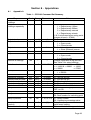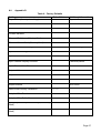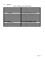
1
Chell Instruments Ltd
Folgate House
Folgate Road
North Walsham
Norfolk NR28 0AJ
ENGLAND
Tel:
Fax:
01692 500555
01692 500088
Chell Configurable
Display
CCD100
OPERATING MANUAL
e-mail:- [email protected]
Visit the Chell website at:
http://www.chell.co.uk
900138-1.3
Please read this manual carefully before using the instrument.
Use of this equipment in a manner not specified in this
manual may impair the user’s protection.
Chell Document No. : 900138 Issue 1.3
ECO: 0579 Date: 19th August 2009
Chell’s policy of continuously updating and improving products means that this manual may contain
minor differences in specification, components and circuit design from the actual instrument supplied.
INDEX
SECTION 1 - INSTRUMENT OVERVIEW....................................................................................................... 1
SECTION 2 - SPECIFICATION ...................................................................................................................... 2
2.1 POWER SUPPLY: ..........................................................................................................................................2
2.2 OPERATING CONDITIONS: ..............................................................................................................................2
2.3 MEASUREMENT AND OUTPUTS: .....................................................................................................................2
SECTION 3 - INSTALLATION AND INTERCONNECTIONS............................................................................... 3
3.1
3.2
3.3
3.4
3.5
TRANSDUCER SOCKET PINOUT - 15 WAY 'D' TYPE .............................................................................................3
INTERFACE SOCKET PINOUT – MINIATURE 15 WAY 'D' TYPE...............................................................................3
SERIAL INTERFACE SOCKET PINOUT - 9 WAY 'D' TYPE ........................................................................................4
POWER CONNECTION SOCKET ........................................................................................................................4
PANEL MOUNTING .......................................................................................................................................4
SECTION 4 - FRONT PANEL OPERATION..................................................................................................... 5
4.1 INTRODUCTION ............................................................................................................................................5
4.2 COMMON SWITCH FUNCTIONS ......................................................................................................................5
(a) Menu screens ......................................................................................................................................5
(b) Editable screens...................................................................................................................................5
(c) Edit mode ............................................................................................................................................5
4.3 HMI BREAKDOWN .......................................................................................................................................6
(a) Main Screen (not changing setpoint) ..................................................................................................6
(b) Main Screen (changing setpoint) ........................................................................................................6
(c) Main Menu Screen ..............................................................................................................................7
(d) Comms Menu Screen...........................................................................................................................7
(e) Setpoint Screen....................................................................................................................................8
(f) Input Screen ........................................................................................................................................8
(g) Filtering Screen....................................................................................................................................9
(h) Serial Screen ........................................................................................................................................9
(i) Relay Screen ..................................................................................................................................... 10
(j) TCP/IP Menu Screen (If TCP/IP Comms are Factory Fitted) ............................................................. 10
(k) IP Address Screen (If TCP/IP Comms are Factory Fitted) .................................................................. 11
(l) Subnet Mask Screen (If TCP/IP Comms are Factory Fitted).............................................................. 11
(m)
Factory Defaults Confirmation Screen ......................................................................................... 12
SECTION 5 - SERIAL & TCP COMMUNICATION ......................................................................................... 13
5.1 INTRODUCTION ......................................................................................................................................... 13
5.2 COMMAND/QUERY FORMAT ...................................................................................................................... 13
5.3 MAIN COMMANDS .................................................................................................................................... 14
(a) Output current readings – ‘r’............................................................................................................ 14
(b) Output current readings repeatedly – ‘rp’ ....................................................................................... 15
(c) Setpoint value – ‘spv’ ....................................................................................................................... 15
(d) Setpoint mode – ‘spm’...................................................................................................................... 15
(e) Setpoint source – ‘sps’ ...................................................................................................................... 16
(f) Setpoint initial value – ‘siv’............................................................................................................... 16
(g) Setpoint initial mode – ‘sim’ ............................................................................................................. 16
5.4 COMMS COMMANDS ................................................................................................................................. 17
(a) Serial baud rate – ‘bra’ ..................................................................................................................... 17
(b) Serial comms protocol – ‘pro’........................................................................................................... 17
(c) Comms address – ‘add’ .................................................................................................................... 17
(d) Ethernet IP address – ‘eip’ (only available if TCP/IP is factory fitted) .............................................. 18
(e) Ethernet subnet mask – ‘esm’ (only available if TCP/IP is factory fitted) ........................................ 18
5.5 CHANNEL SETUP COMMANDS ..................................................................................................................... 19
(a) Input channel units string – ‘uiu’ ...................................................................................................... 19
(b) Input channel range – ‘uir’ ............................................................................................................... 19
(c) Input channel full scale – ‘uif’........................................................................................................... 19
5.6 FILTERING COMMANDS .............................................................................................................................. 20
(a) Filter band – ‘flb’ .............................................................................................................................. 20
(b) Filter size – ‘fls’ ................................................................................................................................. 20
5.7 RELAY CONTROL COMMANDS ...................................................................................................................... 20
(a) Relay trip point – ‘rlt’ ....................................................................................................................... 20
(b) Relay hysteresis – ‘rlh’ ...................................................................................................................... 21
5.8 OTHER COMMANDS................................................................................................................................... 21
(a) User input rezero – ‘irz’ .................................................................................................................... 21
(b) Date of last factory calibration – ‘dlc?’ ............................................................................................ 21
(c) Retrieve all settings – ‘ras’ ............................................................................................................... 21
SECTION 6 - PRINCIPLES.......................................................................................................................... 22
6.1 INTRODUCTION ......................................................................................................................................... 22
6.2 ANALOGUE INPUTS.................................................................................................................................... 22
(a) Range ............................................................................................................................................... 22
(b) Full Scale Voltage ............................................................................................................................. 22
(c) Units String ....................................................................................................................................... 22
6.3 ANALOGUE OUTPUTS ................................................................................................................................ 22
6.4 SETPOINT CONTROL................................................................................................................................... 23
(a) Setpoint Mode .................................................................................................................................. 23
(b) Setpoint Source ................................................................................................................................ 23
6.5 USER REZERO ........................................................................................................................................... 23
6.6 ADAPTIVE FILTERING ................................................................................................................................. 24
(a) Operational band ............................................................................................................................. 24
(b) Filter size .......................................................................................................................................... 24
SECTION 7 - SERVICE AND CALIBRATION ................................................................................................. 25
7.1
7.2
7.3
7.4
7.5
SERVICE ................................................................................................................................................... 25
CALIBRATION............................................................................................................................................ 25
ADJUSTMENT ........................................................................................................................................... 25
CLEANING ................................................................................................................................................ 25
END OF LIFE ............................................................................................................................................. 25
SECTION 8 - APPENDICES ........................................................................................................................ 26
8.1 APPENDIX A ............................................................................................................................................. 26
8.2 APPENDIX B ............................................................................................................................................. 27
8.3 APPENDIX C ............................................................................................................................................. 28
TABLES
Table 1 – CCD100 Command Set Summary ................................................................... 26
Table 2 – Factory Defaults................................................................................................ 27
Table 3 – Settings in ‘ras’ command string..................................................................... 28
Section 1 - Instrument Overview
The CCD100 is a multi featured process display controller, capable of interfacing directly to
a mass flowmeter or other process transducers.
The CCD100 is a single channel unit which can be used to operate a flow controller or
display the output from a pressure transducer. There is also a secondary channel which
can be used for external command (setpoint) control (+5v full scale). The CCD100 also
has the ability to power such devices with either ±15dc @ 250mA or +24vdc @ 300mA.
Interfaces to the CCD100 include RS485, RS232, Ethernet (optional extra) or it can be used
with just analogue signals.
Note: This manual has been written for firmware version 1.00.
Page 1
Section 2 - Specification
2.1
Power Supply:
Line voltage:
Consumption:
Protection:
2.2
24V DC. ±5%
less than 500mA
Internal resettable fuse
Operating conditions:
Operating temperature range:
Storage temperature range:
Maximum Relative humidity:
Warm up time to full accuracy:
2.3
+5°C to +50°C (40°F to 122°F)
-20°C to +70°C (-40°F to 158°F)
95% at 50°C (non condensing)
15 minutes (assumes unit already stabilised at
ambient and excludes transducer warm up time).
Measurement and Outputs:
Power supply out:
DC input signal:
Input impedance:
DC output:
Output accuracy (after zero):
Setpoint (Command) Output:
±15V dc @ 250mA max.
+24V dc @ 300mA max.
Use ±15V or +24V transducer excitation.
Do Not Use Both.
0-10.0V dc
(guaranteed limits are –10.8V to +10.8V
>500 kOhm
Retransmission of Input.
Limits of ±10.8V dc, into 10 kOhm or greater.
± 0.1% of reading ± 0.01% full scale
0-5 V dc.
Close = <0.2 V
Open = >6.0 V
Page 2
Section 3 - Installation and Interconnections
The instrument is designed to be panel mounted, and is a standard 96x48mm panel meter
enclosure. Note that the instrument must always be situated in such a way as to enable
adequate air circulation about the unit.
If a transducer was supplied with the CCD100 a suitable cable may have been included.
3.1
Transducer socket Pinout - 15 Way 'D' Type
Pin Number
2
5
6
7
8
11
12
13
15
All other pins
Designation
Signal
Power Gnd
-15V Supply
+15V Supply
Command Output (V)
Signal Return
Signal Return
+24V Supply
Earth/Chassis
Not Connected
If the transducer is being powered from another source (e.g. a mains powered supply) it
will only be necessary to connect to the two signal pins.
Note: The CCD100 has a fully floating differential input. For single ended use (i.e.
tranducers with differential output) join 0V (pin5) & Signal Return (pin12) at the transducer.
Ensure the common mode input range is not exceded.
3.2
Interface Socket Pinout – Miniature 15 Way 'D' Type
Pin Number
1
2
3
4
5
6
7
8
9
10
11
12
13
14
15
Designation
Analogue Output
Relay 2 Com *
Relay 2 NO *
Relay 2 NC *
0V (Signal Ground)
External Setpoint Return
N/C
External Setpoint
N/C
0V (Signal Ground)
TTL Input – Disable Menu
TTL Input – Disable Zero
Relay 1 Com
Relay 1 NO
Relay 1 NC
* factory fit option
Page 3
3.3
Serial Interface Socket Pinout - 9 Way 'D' Type
Pin Number
1
2
3
4
5
6
7
8
9
1
2
Designation 1 2
RS485 Tx +
RS232 Rx
RS232 Tx
RS485 Tx –
Common
RS485 Rx +
RS485 Rx N/C
Common
For RS232 only, connect only the pins designated in bold font.
For RS485 only, connect only the pins designated in normal font.
The serial protocol must be specified using the HMI, see later.
3.4
Power Connection Socket
The panel meter display requires a 24V, 500mA supply to operate. This must be a rectified
and regulated direct currect supply, capable of 15W (recommended). Although the
CCD100 has an internal fuse and power supply overload shut-down protection the supply
to the CCD100 should be protected by fuse or other suitable electronic method.
A standard 5mm diameter ‘dc power jack’ is required to connect to the CCD100.
Connect the positive conductor to the center pin. Connect the negative (0V) conductor to
the outer of the jack.
If requested, a compatible AC-DC switch mode power supply will have been supplied with
the unit.
Cautions:
Ensure correct power supply rating and polarity.
Do not use a partially assembled or faulty unit.
Incorrect use of this equipment, or use in a manner not specified may
impair the users protection.
3.5
Panel Mounting
A panel mount kit will have been supplied with the instrument. This consists of:
2 M3x6 screws. 2 brackets. 2 50mm screws.
Fit the M3x6 screws into the side of the unit into the diagonally opposed holes. Do not
tighten these screws, to allow the bracket to slide over the screw head. Thread locking
adheasive may be used but is not required as these screws cannot rotate once the bracket
is tightened.
Insert the meter into the panel. A hole cut-out of 92 x 45mm is recommended.
Slip the mounting bracket over the screwhead and tighten the 50mm screw.
The unit should now be secure.
Page 4
Section 4 - Front Panel Operation
4.1
Introduction
The front panel consists of a 112x16 dot matrix VFD display with 6 membrane key switches
below it. Each switch has legends on and above or below it to indicate its function under
different conditions, although there are certain common functions to each screen, as
detailed below.
For the purpose of the following sub-sections, the switches shall be referred to using the
legends on the buttons.
4.2
Common Switch Functions
The switches on certain types of screens and in certain modes, have the same functionality
as detailed here:
(a) Menu screens
On all menu screens, the ‘◄’ & ‘►’ switches are used to navigate through the menu
options. The ‘Func’ switch is used to go back to the parent menu, except on the
Main Menu screen where it goes back to the main screen. The ‘Zero’ switch
doubles up as an Enter switch and this actions the chosen menu selection. This
may be to go to a sub-menu or to an editable or information screen (see HMI
breakdown for more details).
(b) Editable screens
On any screen that has editable fields, switches ‘▲’ & ‘▼’ move the selection
between the possible editable fields. ‘Func’ goes back to the parent screen which is
usually the menu that was used to get to the screen in question. ‘Zero’ activates edit
mode (see below).
(c) Edit mode
When in edit mode, the edit cursor appears on the first character in the editable field
(the cursor is a horizontal bar below the character being edited). If the field is bigger
than 1 character then switches ‘◄’ & ‘►’ are used to move left and right across the
field. If the field is only one character (e.g. a Yes/No selection) or has a rolling
selection (e.g. for selection of a percentage) then ‘◄’ & ‘►’ do nothing. Switches
‘▲’ & ‘▼’ are used to change the character being edited within the valid range (field
position dependant). ‘Func’ cancels edit mode and returns the field to it’s previous
value. ‘Zero’ accepts any changes to the field and also comes out of edit mode.
Page 5
4.3
HMI breakdown
Here follows a complete breakdown of all CCD100 screens:
(a) Main Screen (not changing setpoint)
CLOSE
10.000 mBar
The main screen comes in two forms. The first shows the main channel input data
(with range, full-scale and calibration applied) and the associated units string. If an
input is over range (more than 15% above full scale voltage) then the data value is
replaced with the over range error – “RANGE!”. This screen also shows the current
mode of the setpoint, if not in AUTO (i.e. OPEN or CLOSE). If either of the relays
have been tripped then they are also indicated as such on the far right of the screen.
Switch Functions:
Func
No function *
◄
Go to Main Menu screen
►
Enable setpoint mode override, active for 2 seconds
► (override mode) Change setpoint mode to AUTO
▲
Change setpoint value (main screen changes as below)
▲ (override mode) Change setpoint mode to OPEN
▼
Change setpoint value (main screen changes as below)
▼ (override mode) Change setpoint mode to CLOSE
Zero
Perform input rezero (if held for 3 seconds)
* By default the Func switch does nothing, but special builds of the CCD100 may include functionality for this
switch. In such cases an addendum to this manual will indicate the function.
(b) Main Screen (changing setpoint)
10.000
mBar
SP: 1.000 CLOSE
The other form of main screen is shown when changing the live setpoint (via an
initial press of the ‘▲’ or ‘▼’ switches). All the information shown on the first main
screen is shown here (albeit some items are resized or repositioned) but in addition
the current setpoint value is also shown. Note that this screen is not permanent – if
the ‘▲’ or ‘▼’ switches are not pressed at all for 5 seconds, then the main screen
reverts to the first variety shown previously.
Switch Functions:
Func
No function *(see (a) above)
◄
Go to Main Menu screen
►
Enable setpoint mode override, active for 2 seconds
► (override mode) Change setpoint mode to AUTO
▲
Change setpoint value (hold for continuous change)
▲ (override mode) Change setpoint mode to OPEN
▼
Change setpoint value (hold for continuous change)
▼ (override mode) Change setpoint mode to CLOSE
Zero
Perform input rezero (if held for 3 seconds)
Page 6
(c) Main Menu Screen
Setpoint
►
◄
Input
►
◄
Filtering
►
◄
Comms
►
◄
Relay
►
◄
Factory Def
The Main Menu screen provides a path to select screens that are used for the
configuration of the CCD100 – the setpoint (value, mode, source), input (range, full
scale, units string), comms, display filtering and relays can all be configured from
screens selected via the main menu. It is also possible to reset settings to their
factory defaults from the Main Menu screen. Only one option is shown at any one
time, in the order shown above.
Switch Functions:
Func
◄
►
▲
▼
Zero
Go back to Main screen
Go to previous menu selection
Go to next menu selection
No function
No function
Go to screen associated with menu selection
(d) Comms Menu Screen
Serial
►
◄
TCP/IP
If factory fitted
The Comms Menu screen provides options for setting the Serial comms (baud rate,
address, RS232/RS485 protocol). If TCP/IP comms are factory fitted then this screen
also provides a path to change associated parameters (IP address, Subnet mask).
Switch Functions:
Func
◄
►
▲
▼
Zero
Go back to Main Menu screen
Go to previous menu selection
Go to next menu selection
No function
No function
Go to screen associated with menu selection
Page 7
(e) Setpoint Screen
SP Val: 1.000
Mode: AUTO
▼
From the setpoint screen you can edit the value of the command setpoint as well as
change the mode (AUTO, OPEN, CLOSED) and the source (INTERNAL, SLAVE). If
SLAVE is selected then the percentage sign (%) appears next to the SP value. For
more information on the command setpoint, see the Principles section - 6.4.
Switch Functions:
Func
◄
►
▲
▼
Zero
Go back to Main Menu screen
Select previous character when in edit mode
Select next character when in edit mode
Move edit field selection up
Move edit field selection down
Go to edit mode for currently selected field
(f) Input Screen
Range: 10.000
FS(V): 10.000
▼
This screen allows you to change the input channel range and full-scale voltage
(see the Principles section (6.2) for more information on this) and also assign a units
label (up to 5 characters) for the channel data. The number of decimal places
selected on the range field dictates the number of decimal places shown for the
input channel data on the Main screen. To reduce the number of decimal places,
change the number under the edit cursor to a decimal point and the system will
auto format the field when ‘Zero’ is pressed.
Switch Functions:
Func
◄
►
▲
▼
Zero
Go back to Main Menu screen
Select previous character when in edit mode
Select next character when in edit mode
Move edit field selection up
Move edit field selection down
Go to edit mode for currently selected field
Page 8
(g) Filtering Screen
Band: 0.10 %
Size: 0 sec
This screen allows the user to modify the band and buffer size of the adaptive filter.
The filter only applies to the display and comms output readings. The band is
represented as a percentage of FS and can be set between 0.00% (OFF) and 1.00%
and also to ON. The buffer size allows settings between 0 and 6 seconds of filtering.
For more information on the adaptive filter, see the Principles section (6.6)
Switch Functions:
Func
◄
►
▲
▼
Zero
Go back to Main Menu screen
Select previous character when in edit mode
Select next character when in edit mode
Move edit field selection up
Move edit field selection down
Go to edit mode for currently selected field
(h) Serial Screen
Baud: 57600
Addr: a
▼
The main configuration item on the serial screen allows you to select the baud rate
of the CCD100 for serial communication. The allowed baud rates are 9600, 19200 &
57600. There is also an address field that is mainly used for identifying a particular
unit if several are connected together on an RS485 network. All commands sent to
the unit must be prefixed with the address letter (see section 5.2 for more
information). Valid letters are ‘a’ to ‘h’. The other editable field is used to tell the
CCD100 whether it is on an RS485 serial network.
Switch Functions:
Func
◄
►
▲
▼
Zero
Go back to Comms Menu screen
Select previous character when in edit mode
Select next character when in edit mode
Move edit field selection up
Move edit field selection down
Go to edit mode for currently selected field
Page 9
(i) Relay Screen
Trip Pt: 5.000
Hyst: 2.0 %
▼
This screen allows you to set the trip point for when the relay switches. The relay
also contains some hysteresis to stop it ‘chattering’. This is configurable from this
screen as well and is represented as a percentage of full scale of the input channel,
with limits of 0.0% (i.e. no hysteresis) to 10.0%. If the second relay option is factory
fitted then the above fields are duplicated for the second relay and are changed to
Trip 1, Hyst 1 & Trip 2, Hyst 2 as appropriate.
Switch Functions:
Func
◄
►
▲
▼
Zero
Go back to Main Menu screen
Select previous character when in edit mode
Select next character when in edit mode
Move edit field selection up
Move edit field selection down
Go to edit mode for currently selected field
(j) TCP/IP Menu Screen (If TCP/IP Comms are Factory Fitted)
IP Addr
►
◄
Sub Mask
Due to limited space on the display, the TCP/IP configuration options have to be
place under separate menu selections, as shown here. This menu provides a path
to change the IP address and Subnet mask in their appropriate screens (shown
below).
Switch Functions:
Func
◄
►
▲
▼
Zero
Go back to Comms Menu screen
Go to previous menu selection
Go to next menu selection
No function
No function
Go to screen associated with menu selection
Page 10
(k) IP Address Screen (If TCP/IP Comms are Factory Fitted)
IP Address
192.168.001.180
This screen provides editing of the IP address for TCP communications. Although
any number can be cycled to during edit mode, the CCD100 will cap a particular
octet at 255 if necessary, when ‘Zero’ is pressed to accept the changes.
Switch Functions:
Func
◄
►
▲
▼
Zero
Go back to TCP/IP Menu screen
Select previous character when in edit mode
Select next character when in edit mode
No function if not in edit mode
No function if not in edit mode
Go to edit mode for currently selected field
(l) Subnet Mask Screen (If TCP/IP Comms are Factory Fitted)
Subnet Mask
255.255.255.000
This screen provides editing of the Subnet mask for TCP communications. As with
the IP address above, the CCD100 will cap a particular octet at 255 if necessary,
when ‘Zero’ is pressed to accept the changes.
Switch Functions:
Func
◄
►
▲
▼
Zero
Go back to TCP/IP Menu screen
Select previous character when in edit mode
Select next character when in edit mode
No function if not in edit mode
No function if not in edit mode
Go to edit mode for currently selected field
Page 11
(m) Factory Defaults Confirmation Screen
Hold Menu & Hit
Enter to Confirm
If Factory Defaults is selected from the Main Menu, this screen appears to ask for
confirmation of the requested function. If confirmed then the screen changes to
show a percentage of completion of the factory defaults and once completed the
CCD100 will restart.
Switch Functions:
Func
◄
►
▲
▼
Zero
Go back to Main Menu screen
If held, starts factory default when Zero is pressed
No function
No function
No function
Starts factory default if ◄ is held as well.
Page 12
Section 5 - Serial & TCP Communication
5.1
Introduction
The CCD100 allows full control and feedback via serial communications protocols (RS232
or RS485). If factory fitted, communications is also possible via TCP/IP. All controls via the
HMI are also available via comms and all calibration is also performed via comms
commands.
Serial comms is available using an RS232 or RS485 link between the client (typically a PC)
and the CCD. A baud rate must be configured, along with the selection of protocol. Valid
baud rates are 9600, 19200 & 57600. Additional comms setup parameters (e.g. parity, stop
bits, etc.) are always the same and non-configurable.
By default the CCD is setup to communicate via RS232 with the following comms
parameters:
Baud: 57600
Data bits: 8
Parity: None
Stop bits: 1
Handshaking: None
TCP/IP comms requires an IP address and subnet mask to be configured for the CCD. This
can be set via the HMI or via serial comms. Note that on changing the IP address or subnet
mask, the CCD must be re-initialised by performing a system reset. This is done
automatically if setting from comms (the CCD waits a second and then resets itself), but if
setting from the HMI, you must power off & on for the new TCP/IP settings to come into
effect.
5.2
Command/Query format
The format of the commands and queries is common between all available comms
protocols for ease of use and understanding when switching between comms methods:
Format: accc[?] [p][,p][,p]↵
… where ‘a’ = address, ‘ccc’ = command/query, ‘?’ = query identification; ‘p’ =
parameter (separated by commas if more than one)
The first letter to be entered on the command line, before any command or query, is the
address identifier. This is a letter between a & h and is particularly important when
communicating via RS485, if there are several units on the same RS485 network. On
RS232 and TCP/IP this address doesn’t really mean anything because RS232 is single
point to point comms and TCP/IP uses an IP address per unit for identification. However as
mentioned above, the address letter is left in (and therefore required) for ease of use
between comms methods. By default the CCD has the letter ’a’ for its address.
Most commands are identified by three letters (although this is not always the case) and a
query is identified by following the command letters with a ‘?’ character. For all commands
with parameters, you must separate the command from its parameters with a space, and
separate multiple parameters with commas.
Page 13
Table 1 in Appendix A summarises all commands and queries available. Note that where a
command is also a query, you do not enter any parameters for the query ‘version’ unless
explicitly stated in the table.
For everything sent on the comms port, the CCD will reply by informing the user of the
command/query it has just received, along with any parameters identified, any data
requested (if it was a valid command/query) and a line indicating whether the command
was accepted. This reply block is the same for anything sent to the CCD and is as follows .
(‘↵’ indicates a carriage return/line feed pair):
For a command:
*<a>*:<cmd>;<params>↵
!<a>!<response>!↵
For a query:
*<a>*:<cmd>;<params>↵
<data>↵
!<a>!<response>!↵
where:
<a> is the address letter
<cmd> is the command/query (query identified by a ‘?’ after the three chars)
<params> is the comma separated parameter list, if any
<response> is the acceptance indicator.
<data> is the data requested if a query was sent. Note the data usually
consists of some identification string, in CAPS, followed by a colon (:) and then the actual
data. Some queries return multiple lines of information. See individual commands for
details as appropriate.
The acceptance indicator is a single character as follows:
• ‘o’ = OK: if the command/query was recognised and accepted;
• ‘b’ = BADCMD: if the command/query was not recognised or has incorrect/invalid
parameters
• ‘e’ = ERROR: if there was some internal comms error.
• ‘w’ = BUSY: if the comms is currently busy.
5.3
Main commands
(a) Output current readings – ‘r’
This command tells the CCD to get the current reading of the input channel data and
output to the comms. If the input voltage of the channel is more than 15% over the full
scale voltage set for the channel, the <reading> below will be replaced with the over
range error – “RANGE!”.
The readings output format is as follows with the channel data followed by a setpoint mode
indication, separated by a semi-colon:
READ:<reading>;<setpoint mode>↵
The <setpoint mode> is a single number that represents the current mode of the setpoint:
0 = Auto, 1 = Open, 2 = Closed. This number is mainly included for use with Chell’s frontend software (CCD-X) and is mainly useful when outputting repeated readings, where it
effectively provides a constant update of the current mode of the setpoint.
Page 14
(b) Output current readings repeatedly – ‘rp’
The CCD is also able to report the current readings repeatedly, at a given interval. This
command starts and stops this repeat activity by setting the parameter accordingly:
0 = Repeat off
1 = Repeat every 100ms (not allowed if using serial comms baud < 57600)
2 = Repeat every 500ms (not allowed if using serial comms baud < 57600)
3 = Repeat every second
4 = Repeat every minute
The timing commences from the point at which the ‘rp’ command is entered.
Use this command with care on a RS485 multidrop network! ‘r’ is recommended.
NOTE for 100ms repeat readings: The data output is effectively lots of small data
packets. On TCP networks this can cause problems when communicating with front end
software running on MS Windows. It has been found that the Winsock control commonly
used in TCP comms development on Windows does not handle lots of small data packets
very well, coming in at speeds of around 10Hz or faster. As such it has been decided that
when 100ms repeated output is used, the data will be taken every 100ms and buffered up,
to be sent out every 500ms in blocks of 5 readings. This has proven to be a more robust
output method. For consistency, the output from serial comms also works in the same
way.
(c) Setpoint value – ‘spv’
This command is used to set the value of the command setpoint. The command takes one
parameter which is the actual value to set.
The current value of the setpoint can be retrieved using the query ‘spv?’. Returned data is:
SP VALUE: <setpoint value>
(d) Setpoint mode – ‘spm’
This command sets the mode for the command setpoint. The command takes one
parameter which is a number between 0 & 2, identifying the mode, as follows:
0 = Auto mode
1 = Open mode
2 = Closed mode
(For more information on setpoint modes, see the Principles section - 6.4(a)).
The current mode of the setpoint can be retrieved by using the query ‘spm?’. The returned
data is:
SP MODE: (<x>) <mode string>
… where …
<x> = 0, 1, or 2 and <mode string> = AUTO, OPEN, or CLOSED respectively.
Page 15
(e) Setpoint source – ‘sps’
The setpoint source can be an internally set value or a percentage of the secondary CCD
input (known as slave input). This source is set using this command and as with the other
setpoint commands, it takes just one parameter which isas follows:
0 = Internal source
1 = Slave source
(For more information on setpoint sources, see the Principles section - 6.4(b)).
The current source of the setpoint can be retrieved by using the query ‘sps?’. The returned
data is:
SP SOURCE: (<x>) <source id>
…where…
<x> = 0 or 1 as above, <source id> = string identifier for <x> : INTERNAL or SLAVE.
(f) Setpoint initial value – ‘siv’
The setpoint value set with the ‘spv’ command (above) is not non-volatile. This command
can be used to set an initial setpoint value on system startup. It takes one parameter which
is the initial setpoint value.
The current value of the setpoint can be retrieved using the query ‘siv?’. Returned data is:
SP INIT VAL: <initial setpoint value>
(g) Setpoint initial mode – ‘sim’
As with the value, the setpoint mode set using the ‘spm’ command (above) is a volatile
setting. Again this command provides a way of setting an initial startup mode for the
setpoint on power up of the CCD. It takes one parameter which is a number between 0 &
2, identifying the initial mode, as follows:
0 = Auto mode
1 = Open mode
2 = Closed mode
The current mode of the setpoint can be retrieved by using the query ‘spm?’. The returned
data is:
SP INIT MODE: (<x>) <mode string>
… where …
<x> = 0, 1, or 2 and <mode string> = AUTO, OPEN, or CLOSED respectively.
Page 16
5.4
Comms commands
(a) Serial baud rate – ‘bra’
The serial baud rate can be set using this command. Any value can be entered as the
parameter and the CCD decides on the actual baud rate using the following criteria:
Parameter value
< 14400
>= 14400 & < 28800
>= 28800
Actual baud rate
9600
19200
57600
If the current comms used is serial, then the CCD will give the usual response to the
command at the current baud, then change baud rate and give the !<address>!o!↵
response at the new baud rate. Host front ends can therefore monitor for this to confirm
that the baud rate has changed. If this command is used with TCP comms then you will
simply see the OK response twice as the CCD changes baud and confirms.
To retrieve the current baud, use the query ‘bra?’. Returned data is:
BAUD: <baud rate>
(b) Serial comms protocol – ‘pro’
This command switches the serial comms protocols between RS232 & RS485. The
parameter passed should be one of the following:
0 = RS485
1 = RS232
To retrieve the current protocol setting, use the query ‘pro?’. Returned data is:
PROTOCOL: <protocol> … where <protocol> = 0 or 1 as above.
(c) Comms address – ‘add’
As mentioned previously (section 5.2), all commands are prefixed with an address letter.
This command allows you to change that address. Valid addresses are a-h. When the CCD
replies to the command, the first line will contain the old address and the response line will
contain the new address. All subsequent comms must use the new address.
The current comms address can be obtained using the query ‘add?’. The returned data is:
ADDR: <address>
Page 17
(d) Ethernet IP address – ‘eip’ (only available if TCP/IP is factory fitted)
This command changes the IP address used to communicate over TCP/IP comms. The
parameter should be entered as a standard 4 octet IP address. e.g. 192.168.1.180. The
max octet value is obviously 255. If a greater value is entered, that value will be capped to
255. Once the CCD has responded to the command, it will display the following and autorestart the system.
UNIT SHOULD AUTO RESTART↵
IF NOT, RESTART TO APPLY CHANGES↵
This is necessary to re-initialise the internal TCP socket with the newly set IP address.
To retrieve the current IP address, use the query ‘eip?’. The returned data is:
IP ADDRESS: <xxx>.<xxx>.<xxx>.<xxx>
…where <xxx> is always a three digit octet.
(e) Ethernet subnet mask – ‘esm’ (only available if TCP/IP is factory fitted)
This command changes the Subnet mask used as part of the TCP/IP communication. As
with the IP address, the parameter should be entered as a standard 4 octet mask. e.g.
255.255.255.0. Each octet value is again capped if a value greater than 255 is entered.
The CCD will respond and the display the following before auto-restarting the system (as
with the IP address).
UNIT SHOULD AUTO RESTART↵
IF NOT, RESTART TO APPLY CHANGES↵
The current subnet mask can be retrieved using the query ‘esm?’. The returned data is:
SUBNET MASK: <xxx>.<xxx>.<xxx>.<xxx>
…where <xxx> is always a three digit octet.
Page 18
5.5
Channel Setup commands
(a) Input channel units string – ‘uiu’
The input channel has an associated free-form text field that can be used to identify the
units being used. This command is used to set this and its only parameter is a max of 5
characters for the units string.
The current units string can be retrieved using the query ‘uiu?’. The data returned is as
follows:
INPUT UNITS STR: <units>
… where…
<units> = the exact units string as displayed on the front panel
(b) Input channel range – ‘uir’
Use this command to set the range of the input channel. The single parameter is the actual
value for the range. The number of decimal places passed in the range value dictates the
number of decimal places shown for the main data output (up to a max of 4 decimal places
– any more will get chopped off)
The current range of the input channel is retrieved using the query ‘uir?’. The data returned
is as follows:
INPUT RANGE: <range>
… where…
<range> = the range of the channel (engineering units)
(c) Input channel full scale – ‘uif’
This command is used to set the full scale voltage for the input channel. The single
parameter is the actual full scale value.
The full scale voltage setting for the input channel is retrieved using the query ‘uif?’. The
data returned is as follows:
INPUT FULLSCALE: <fs>
… where…
<fs> = the full scale voltage of the channel
For more information on the use of input range and full scale, see the Principles section 6.2.
Page 19
5.6
Filtering commands
(a) Filter band – ‘flb’
This command is used to set the point at which the adaptive filtering kicks in. It takes one
parameter which is the percentage of full scale of the input. Valid values are between
0.01% and 1.00%. Additionally the parameter can be OFF which will mean the filtering will
never kick in, or ON which means the filtering is always used. Note that if the filter size is
set to greater than 5 seconds, the filter band command will return a Bad Command
acknowledgement because the filter is always on in this situation and it therefore makes no
sense to attempt to change the band setting. For more information on this see the
Principles section (6.6).
To retrieve the current filter band, use the query ‘flb?’. The returned data is:
FILTERING BAND: <band>%
(b) Filter size – ‘fls’
Use this command to set the size of the adaptive filtering buffer. The one parameter this
command takes is the buffer size in seconds, between 0 and 6 seconds. (0 can be used to
effectively turn the adaptive filtering off).
To retrieve the current filter size, use the query ‘fls?’. The returned data is:
FILTERING SIZE: <x> sec
… where <x> = number of seconds of filtering
[Note if current size is 0 then returned data is: FILTERING SIZE: 0 (NO FILTER) ]
5.7
Relay control commands
(a) Relay trip point – ‘rlt’
This command sets the point at which the relay switches from one state to the other. When
the source data is below this point then the relay is closed, so therefore when the source
data rises above this point then the relay is open. The command takes two parameters –
the first is the relay whose trip point is to be set (1-2) and the second is the trip point in
engineering units, as configured with the Input Channel range command (see 5.5(b)). Note
that the first parameter is always required even if the second relay has not been factory
fitted.
The current trip point values can be retrieved using the query ‘rlt?’. The returned data is
one line for each relay, as follows:
RELAY <x> TRIP POINT: <trip point, in engineering units >
… where ...
<x> = the relay number
Page 20
(b) Relay hysteresis – ‘rlh’
This command configures the hysteresis setting of the relay. It takes two parameters – the
first if the relay in question, the second is the percentage hysteresis, represented as a
percentage of full scale of the source channel, with limits of 0.0% (i.e. no hysteresis) to
10.0%.
The current hysteresis setting can be retrieved using the query ‘rlh?’. The returned data is
one line for each relay, as follows:
RELAY <x> HYSTERESIS: <hysteresis percentage>%
… where ...
<x> = the relay number
5.8
Other commands
(a) User input rezero – ‘irz’
To perform a user input rezero function, use this command. Typically the command takes
no parameters to perform the function, although it can take an optional parameter of ‘0’
which clears any value already generated by a previous rezero.
To find the current user rezero value use the query ‘irz?’. The data returned is as follows:
REZERO: <rezero>
…where…
<rezero> = the current rezero value
(b) Date of last factory calibration – ‘dlc?’
This query is used to retrieve the date of the last factory calibration run. The data is
returned as follows:
LAST CAL DATE: <yymmdd>
…where yy = year, mm = month & dd = day.
E.g. 051201 means the last calibration run was 1st December 2005.
(c) Retrieve all settings – ‘ras’
As well as issuing some of the above commands as queries to retrieve individual settings,
this command has been provided which will return a comma separated list of most of the
settings for the input channel, setpoint, etc.
The exact settings provided by this command are detailed in Table 3 in Appendix C.
Page 21
Section 6 - Principles
6.1
Introduction
This section describes the principles used in the CCD100. It details the various settings for
the inputs and the outputs including setpoint control. It does not detail any servicing or
calibration procedures.
6.2
Analogue Inputs
The CCD100 has two analogue voltage input channels. The main input can be configured
to accept any input voltage from 0V to a full scale of up to 10V. This input is calibrated
using a straight line fit method and then can be displayed on the CCD with an applied
range. The secondary input is used to accept an external command setpoint and has a
non-configurable full scale of 5V. This input is used when the setpoint is set to slave
source.
The main input channel has a number of associated setup parameters:
(a) Range
Each device attached to the CCD will be outputting a voltage that represents some
form of units and the range is used with the full scale to determine what the user
sees on the screen for any input voltage.
(b) Full Scale Voltage
Each device attached to the CCD will have a full scale voltage which is the
maximum voltage the device should output under normal operating conditions.
Typical values are 10V, 5V and 1V. The full scale is used with the range to determine
what the user sees on the screen for any input voltage. The CCD will show the over
range error (“RANGE!”) for any channel whose voltage input is more than 15% over
the full scale voltage set for that channel.
(c) Units String
To inform the user of what units are being dealt with, each channel has an
associated units string. This is a free form text field (maximum 5 characters) that is
displayed on the right side of the Main screen.
Example
A device has a full scale voltage of 10V and a range of 100 mbar.
If the device now outputs 10V, the CCD100 display will nominally show 100 (pending input
calibration). If the device outputs 5V, the CCD100 will show 50, and so on.
Analogue Outputs
6.3
There are two analogue outputs on the CCD100, both voltage outputs. One is for setpoint
control with its own set of setup parameters (see next section) and the other is a simple
retransmission of the main input voltage and has no user setup control. Typically this
output can be used for data logging purposes or for providing an external setpoint control
to another CCD or similar instrument.
Page 22
6.4
Setpoint Control
As mentioned above, there is one analogue output that is used for command setpoint
control that can be used to operate a mass flow controller or similar. The setpoint
command output always has a voltage full scale of 5V.
Example
If the input channel is setup for a 100 slpm 5V full scale device, and the setpoint value is
10.0 (assuming setpoint is in Auto mode and not a slave source), then the output voltage
of the setpoint would be 0.5V.
The setpoint does have some configuration parameters that can be used to alter the
function of the setpoint control and they are detailed as follows:
(a) Setpoint Mode
The setpoint can be configured in one of three modes – Auto, Open and Closed.
• In Auto mode the setpoint output is dependant on the setpoint source and value
settings (see below).
• In Open mode the setpoint outputs a voltage greater than the full scale of the
device. Given that the setpoint command full scale is 5V, the output in this mode
is 7V.
• In Closed mode the setpoint outputs a voltage less than the minimum output
voltage of most devices, the setpoint output voltage is –0.25V.
(b) Setpoint Source
The setpoint source dictates where the setpoint value comes from, assuming the
mode is set to Auto (see above). This can be one of two possibilities – Internal or
Slave.
• Internal source – the setpoint uses the value set internally via the ‘▲’ & ‘▼’
switches or via the externals comms.
• Slave source – in this case the setpoint uses a percentage of an externally
produced value. The percentage is set via the ‘▲’ & ‘▼’ switches and the external
value comes from the secondary input channel (as mentioned 6.2 in above)
6.5
User Rezero
Over time it is possible that the input may ‘drift’ slightly due to various conditions
(temperature changes, etc.). As such it may be necessary for the channel to be rezeroed
by the user.
The user rezero function is provided for this task. It simply takes the current reading
(sampled and averaged over 3 seconds) and uses that as an additional offset for the
channel in question, subtracting the value from all subsequent readings. Ensure any
process value to be zeroed, is in fact truly zero before performing this function. This would
mean isolating flow devices or fully pumping a pressure device.
Note that the user rezero via comms also provides the facility for clearing any user rezero
value that may have already been set. This should be used before any input calibration is
performed to ensure that the calculated calibration points are not distorted by the user zero
offset.
Page 23
6.6
Adaptive Filtering
The CCD100 includes an adaptive averaging filter on the display and comms readings
output to aid in ‘smoothing out’ unwanted ‘noise’ on the displayed readings.
(a) Operational band
The filter can be configured to only operate within a certain band, meaning that
excursions between subsequent readings that fall outside that band are shown as
real (and not filtered) readings. The band is configurable between 0.01% and 1.00%
of the full scale range of the input channel. It can also be set to OFF, which means
that no filtering is performed (i.e. every reading is a ‘real’ one) and can also be set to
ON which means that filtering is always shown no matter how big of an excursion
occurs.
(b) Filter size
The size of the filter is currently configurable between 0 and 6 seconds and simply
indicates the amount of readings that are taken and buffered to calculate and show
the averaged reading. A filter size of 0 will naturally turn of the filtering, irrespective
of the band setting.
It should be noted that this type of adaptive filtering can cause readings to be displayed
abnormally, particularly if the buffer size is one of the larger available settings, where the
displayed readings seem to ‘jump about’ as the filter is disabled and then re-enabled when
the data excursions fall into the pre-set band. This is because outside of the band, the
display will show the ‘real’ unfiltered readings (whilst constantly taking an average in the
background). When the excursions fall into the band then the display will switch to
showing the filtered data. If this data is quite significantly slugged (due to a large buffer
size) then the display will appear to nearly reach the new data value (due to ‘real’ values
being shown) and then jump back to the filtered data which could be several seconds
behind. Because of this, the setting of a buffer size greater than 5 seconds will
automatically change the band to ON, meaning that filtered data will always be shown.
Selecting different filter band/size combinations will reduce these anomalies, turning the
band OFF and ON will stop this anomaly.
Page 24
Section 7 - Service and Calibration
7.1
Service
There are no user serviceable parts inside the instruments. Should any difficulties be
encountered in the use of the CCD100, it is recommended that you contact Chell
Instruments Ltd for advice and instructions.
7.2
Calibration
There is no user calibration for the CCD100. It is recommended that the instrument
be returned annually to Chell Instruments Ltd for a ‘factory calibration’. This will
ensure optimum performance throughout the life of the product.
7.3
Adjustment
There are no user adjustments in the instrument, indeed, the presence of lethal
voltages within the instrument means that the user is strictly forbidden from
removing the covers without invalidating Chell’s obligations under both Warranty
and COSSH.
7.4
Cleaning
A dirty instrument may be wiped clean with a soft cloth that has been sprayed with a
proprietary ‘foaming cleaner’, then wiped dry immediately.
Under no circumstances should the instrument be wetted
directly or left damp
7.5
End of Life
Chell Instruments Ltd complies with the WEEE legislation and is registered as a
manufacturer and importer of Electrical and Electronic Equipment.
Once this equipment reaches its end of life, or is no longer required it may be
returned to Chell Intruments Ltd to be reused or recycled in accordance with the
legislation. Please contact Chell Instruments Ltd for full details. Terms and
conditions apply.
Page 25
Section 8 - Appendices
8.1
Appendix A
Table 1 – CCD100 Command Set Summary
Purpose
Output current
readings
Output current
readings repeatedly
Cmd
r
Query
---
Parameters
---
Notes
rp
---
0-4
Setpoint value
Setpoint mode
spv
spm
spv?
spm?
#
0-2
Setpoint source
sps
sps?
0-1
Setpoint initial value
Setpoint initial mode
siv
sim
siv?
sim?
#
0-2
Retrieve all settings
ras
---
---
Serial baud rate
bra
bra?
9600-57600
Serial protocol
pro
pro?
0-1
P1: 0 = Repeat off
1 = Repeat every 100ms
2 = Repeat every 500ms
3 = Repeat every second
4 = Repeat every minute
(1 & 2 not allowed when using serial
comms at baud < 57600)
P1: Real value to set
P1: 0 = Auto mode
1 = Open mode
2 = Closed mode
P1: 0 = Internal source
1 = Slave (External) source
P1: Real value to set
P1: 0 = Auto mode
1 = Open mode
2 = Closed mode
Comma separated string returned
See Table 3 for actual settings
< 14400 ⇒ 9600
>= 14400 & < 28800 ⇒ 19200
>= 28800
⇒ 57600
P1: 0 = RS485
1 = RS232
Comms address
Ethernet IP address
Ethernet subnet mask
Input channel units str
Input channel range
Input channel full scale
Adaptive filter band
add
eip
esm
uiu
uir
uif
flb
add?
eip?
esm?
uiu?
uir?
uif?
flb?
a-h
IP octets
IP octets
ccccc
#
#
#
Adaptive filter size
Relay switch threshold
fls
rlt
fls?
rlt?
0-6
1-2,#
Relay hysteresis
rlh
rlh?
1-2,0.0-10.0
User input rezero
function
Date of last calibration
irz
irz?
[0]
---
dlc?
P1: xxx.xxx.xxx.xxx
P1: xxx.xxx.xxx.xxx
P1: Max length 5 chars
P1: Real value for range to set
P1: Real value for full scale to set
P1: Band percentage (0.01-1.00) or
OFF, or ON
P1: Buffer size in seconds
P1: Relay number
P2: Real number for switching point
P1: Relay number
P2: Hysteresis percentage value
P1 (optional): clears current user
input rezero setting
Returned date format: yymmdd
Page 26
8.2
Appendix B
Table 2 – Factory Defaults
Setting
Repeat Rate (for output readings)
Default Value
Additional Information
Repeat off
0
Serial Comms Baud
57600
Serial Comms Protocol
1
Comms Address
a
Ethernet IP Address (if factory fitted)
192.168.1.180
Ethernet Subnet Mask (if factory fitted)
255.255.255.0
Input Channel Units String
“”
Input Channel Range
10.00
Input Channel Full Scale
10.000
Input Channel Display Precision
2
2 decimal places
Input Channel User Rezero
0.0
No rezero set
Setpoint Value
0.0
Setpoint Slave Value
0.0%
Setpoint Source
0
Internal source
Setpoint Mode
0
Auto mode
Date of Last Factory Calibration
010101
Adaptive Filter Band
0.2%
Adaptive Filter Buffer Size
2
RS232
No units strings set
2 seconds
Relay Trip Point (for both relays, if factory 10.0
fitted)
Relay Hysteresis (for both relays, if factory 2.0%
fitted)
Page 27
8.3
Appendix C
Table 3 – Settings in ‘ras’ command string
Description
Input channel units string
range
full scale
Setpoint value
slave value
mode
source
initial value
initial slave value
initial mode
Adaptive filter band
size
Relay 1 trip point
hysteresis value
Relay 2 trip point (if factory fitted)
hysteresis value (if factory fitted)
Last factory calibration date
Type and size
5 char string
8 char string representation of a float
8 char string representation of a float
8 char string representation of a float
8 char string representation of a float
1 byte (0-2 as for spm? query)
1 byte (0-1 as for sps? query)
8 char string representation of a float
8 char string representation of a float
1 byte (0-2 as for sim? query)
4 char string representation of a float
1 byte (0-6 as for fls? query)
8 char string representation of a float
4 char string representation of a float
8 char string representation of a float
4 char string representation of a float
6 char string (format as for dlc? query)
Page 28