1
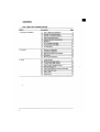
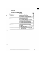
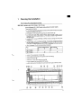
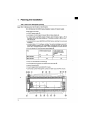
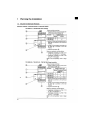
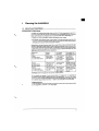
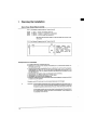
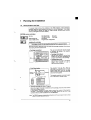
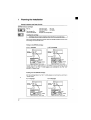
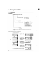
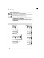
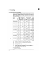
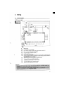
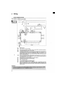
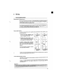
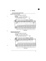
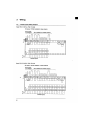
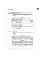
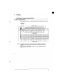
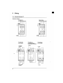
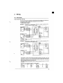
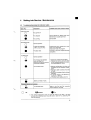
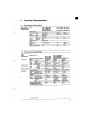
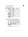
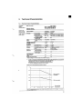
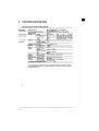
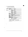
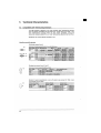
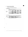
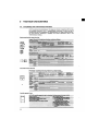
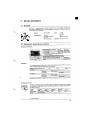
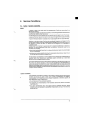
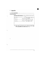
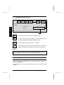
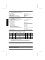
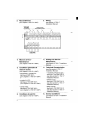
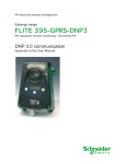
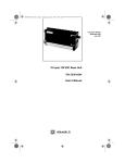
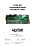
TSX 17B 1428 BATIBUS Micro-PLC - Follow-up Sheet
Apart from the specific product features indicated on this follow-up sheet, the
general instructions for installing the TSX 17B 1428 Micro-PLC are the same as
those given in the TSX D11 000E Installation Manual.
1
Planning the Installation (see Section 1 in TSX D11 000E)
1.1
Description of TSX 17B 1428 PLC
These systems comprise:
• a 110/240 VAC power supply that provides a 24 VDC, 250 mA supply output
for 24 VDC sensors connected to the TSX 17,
• a CPU with programming port and status display ,
1
3
2
4
• an internal 24 Kbyte RAM program memory (and 2 Kbytes of data) that can be
backed up. The battery is located in and has a 1 year service life.
• a location for a plug-in EEPROM or EPROM memory cartridge for saving user
programs,
• a location for a PL7-2 software cartridge containing the BATIBUS function,
• 14 discrete I/O with front panel status display :
- 12 isolated 24 VDC inputs
- 2 relay outputs
5
6
(
8
•
•
•
•
•
9
7
"
9
a BATIBUS network with front panel status display ,
a 15 V, 150 mA power supply energizing the BATIBUS network,
a 9-pin I/O bus extension connector ,
2 removable terminal strips with captive screw terminals,
a ground connector .
é
§
3
'
§ 1
8
2
(
&
é
7
6
'
é
" 45
9
&
7
E
N
G
L
I
S
H
1.2
0
BATIBUS Network Status Display
DEF
1
NET
DATA
ON
BUS
MD
SORTIES
OUTPUTS
ENTREES
4 digit readout
E
N
G
L
I
S
H
INPUTS
0
1
2
3
4
5
6
7
8
9
10
11
Contents of SW 16
DEF
This LED comes on when there is a BATIBUS fault
NET
This LED comes on when one of the system components is faulty, i.e.
no acknowledgement or BATIBUS interface problem
DATA
This LED flashes during transmission or reception
ON
This LED comes on when the line is energized by 15 V. It thus permits
detection of line short-circuits and of a cross-connected module.
Important
The contents of word SW16 can be displayed in 4 digit BCD format by setting SY 14 to
state 1 through PL7-2 programming. In this case the status display of both outputs (0,1)
and of the BATIBUS network (DEF, NET, DATA, ON) is no longer active.
2
Mounting
• Basic PLC/extension compatibility: as for TSX 172 3428 (see Section 2.3 in
TSX D11 000E Manual)
• overall dimensions: as for TSX 172 3428 (see Section 2.4 in TSX D11 000E
Manual)
8
TSX 17B 1428 BATIBUS Micro-PLC - Follow-up Sheet
3
Wiring (see Section 3 - TSX D11 000E)
Power supply
110 to 240VAC
~
24 to 240VAC
or 24VDC outputs
+ - + or or
~
~
C
N L C
0 0 1 1
110V
240V
BATIBUS line powered
by internal 15 V
+ -
- +
POW
15 V
BUS
Connect shielding
to PLC side
E
N
G
L
I
S
H
50/60Hz
0V
0 1 2 3 4 5 6 7 8 9 10 11
0,25 A
24
0V V 0 1 2 3 4 5 6 7 8 9 10 11
24 VDC inputs
4
Setting into Service - Maintenance
(See Section 4 in TSX D11 000E)
5
Technical Characteristics
5.1
Power Supply Characteristics: the same 110/240 V power supply as for
TSX 172 3428 (see Section 5.1 in TSX D11 000E)
5.2
24 VDC Input Characteristics: as for TSX 172 3428
5.3
Discrete Output Characteristics: relay outputs as for TSX 172 3428
5.4
BATIBUS Network Characteristics
5.4.1 Principle of Coding/Decoding
The modules in the network are powered by 15 V supplied by the TSX 17B 1428 PLC.
Modulation is achieved by pinching off the powered line. The physical layer transmits
or receives the coded frames.
Line at rest
: 15 V (logic state of 0)
Pinched line
: 0 V (logic state of 1)
9
5.4.2 15 V Power Supply Characteristics
•
•
•
•
•
No load voltage
Voltage under load
Pinch-off current
Isolation between mains and bus
Capacitance between line and mains
15.5 V ± 10%
13.8 V min. at 150 mA
300 mA ± 10%
4000 Vrms
50 pF
5.4.3 BATIBUS Line Characteristics
E
N
G
L
I
S
H
• Transmitter Network
- Voltage across line terminals at pinch-off
- Leakage current on line at rest
• Receiver Network
- Input resistance
- Line resistance
-
Line voltage drop
Line capacitance
Spurious capacitance at a point
Pinch-off-to-breakdown and
breakdown-to-pinch-off switchover times
- Modulation rate
1.5 V max. with 330 mA
50 µA at 18 V
500 K Ω max.
12 Ω max. between power
supply and most distant point
3.6 V max.
250 nF max.
50 pF max.
2 µs min., 5 µs max. with no
load on line
4800 bps (bits per second)
5.4.4 Recommended Cable
• BATIBUS cable (P/N 63715) marketed by Merlin Gerin.
Name
Area
mm2
Isolation
(1)
Type or
shielding
Screen
I
m
L
m
R/km
BATIBUS
0.75
4 KV
flexible
yes
250
1900
46.2
BATIBUS
1.5
4 KV
flexible
yes
500
2500
24.2
BATIBUS
2.5
4 KV
flexible
yes
600
2500
15.2
I
:
L :
(1) :
max. length from processor (or sub-station) to most distant BATIBUS point.
max. length of overall BATIBUS network.
isolation between the conductors and the screen or shielding when present;
otherwise between the conductors and the outside surface of the wire.
5.4.5 Special Wiring Precautions
Whenever possible keep the BATIBUS cable at least 20 cm away from power cables.
6
Service Conditions
(see Section 6 in TSX D11 000E)
10