1
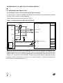
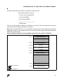
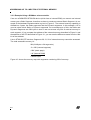
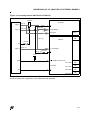
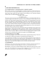
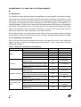
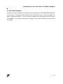
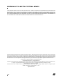
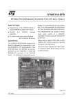
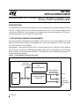
AN1069 APPLICATION NOTE ADDRESSING UP TO 4 MBYTES OF MEMORY FROM A ST9+ WITH A 16-BIT EXTERNAL BUS By Microcontroller Division Applications INTRODUCTION This application note is to help developers of ST9+ applications that need to address external memory. It refers to ST9+ microcontrollers which have only a 16-bit external address bus (such as the ST90158). The information in this application note does not apply to ST9+ microcontrollers that have a 22-bit external address bus. 1 ST9 EXTERNAL MEMORY MANAGEMENT Through the Memory Management Unit (MMU), ST9+ devices can internally address up to 4M bytes of linear memory using a 22-bit address bus (refer to the datasheet or ST9+ user guide for more information on the MMU). Nevertheless, most general purpose ST9+ microcontrollers do not output this 22-bit address bus, they only output the 16 Least Significant Bits (LSBs) of the 22-bit address. This 16-bit address is output on two 8-bit ports: P0 and P1. This allows the user to address 64 Kbytes (216 ) of external memory directly. Figure 1. ST9+ Memory Access Overview 8-BIT DATA 22-BIT ADDRESS ST9+ INTERNAL MEMORY 16-BIT ADDRESS MULTIPLEXED WITH 8-BIT DATA P0[0..7] CORE EXTERNAL MEMORY INTERFACE P1[0..7] AS, RW, DS, DS2 (ST92F120 only) AN1069/0700 1/14 1 ADDRESSING UP TO 4 MBYTES OF EXTERNAL MEMORY In the first part of this application note we will see how to use the existing interface to address 64 Kbytes or 128 Kbytes (ST92F120 only) of external memory without any additional software overhead. In the second part we will see how to address almost 2 Mbytes with a ROMLESS or almost 4 Mbytes with an OTP/EPROM/FLASH device. This last solution uses the P2 I/O port to output the 22-bit address. 2 ACCESSING UP TO 64 KBYTES OF EXTERNAL MEMORY WITHOUT SOFTWARE OVERHEAD The ST9+ outputs a 16-bit address multiplexed with the 8-bit data. So, to access 64 Kbytes of memory, we only need to make the correct hardware connections between the memory devices and the microcontroller. These connections are described in Figure 2.. Figure 2. Accessing 64 Kbytes of external memory EXTERNAL MEMORY 64 K 74HC573 ST9+ 16-bit address P0 OTP ROM ROMLESS FLASH LE P1 8-bit data 74HC04 ROM M27C1001 AS DS G RAM M48Z64Y Flash M29F010b VCC R/W R/W (RAM and Flash only) E The R/W signal is only needed for RAM and Flash or mixed memory components. The pull-up resistor is needed only when using ROMLESS devices. Examples of memory mapping are given in Figure 3. and Figure 4.. 2/14 2 ADDRESSING UP TO 4 MBYTES OF EXTERNAL MEMORY Figure 3. Memory mapping for 64K of external memory with ST90158 (OTP) Seg 3F Unused Seg 23 Unused Seg 22 Reserved Seg 21 Reserved Seg 20 RAM 1K Seg 1F Unused Seg 2 Unused Seg 1 64K External Memory Seg 0 64K Internal ROM Figure 4. Memory mapping for 64 K of external memory with ST90R158 (ROMLESS) Seg 3F Unused Seg 23 Unused Seg 22 Reserved Seg 21 Reserved Seg 20 1K RAM Seg 1F Unused Seg1 Unused Seg0 64K External Memory 3/14 ADDRESSING UP TO 4 MBYTES OF EXTERNAL MEMORY 3 ACCESSING UP TO 2 OR 4 MBYTES WITH ANY ST9+ 3.1 PRINCIPLE As previously mentioned in Section 1, the ST9 handles 22-bit addresses internally but outputs only the 16 LSBs of the address through the external memory interface. In this section we will see how, by handling it in software, it is possible to access almost 2M with a ROMLESS device or almost to 4M bytes with an OTP, ROM, or Flash device. To access more than 64K of external memory, you need to output the 6 Most Significant Bits (MSBs) of the address. To do this, we have chosen to use the 6 LSBs of Port 2 (refer to Figure 5.). Port 2 will be used by software to select the Dynamic Segment you want to access. External memory segments and Internal memory segments are two different addressable areas. For simplicity, both types of segment are numbered in the same way. Figure 5. ST9+ Schematic 8-bit data bus ST9+ internal memory 22-bit address 16-bit address multiplexed with 8 bit data bus External Memory Interface P0[0..7] CORE P1[0..7] AS, R/W, DS, DS2 (ST92F120 only) I/O port logic 4/14 P2[0..5] ADDRESSING UP TO 4 MBYTES OF EXTERNAL MEMORY Figure 6. Static and Dynamic Segments Dynamic segments External memory Static Segments Internal or External memory 3.2 DEFINITION STATIC SEGMENT (SS): A segment of memory which can always be accessed whatever the value of the Dynamic Segment selected (value of Port 2 data register: P2DR). In an OTP/ ROM/FLASH microcontroller, the internal memory can always be accessed and therefore is contained in static segments. For example in the ST90158, Segment 0 (ROM) and Seg 20 (RAM) are static segments The size of the memory in a segment can be from zero to 64K. The number of static segments and the amount of memory in each segment depends on the microcontroller. In the case of ROMLESS devices, the static segment must be a special area of external memory which is not connected to Port 2 and is therefore not dynamic. At least one static segment is needed in any application. DYNAMIC SEGMENT (DS): A segment of the external memory which is accessible only if it has been selected by the user. Its access depends on the P2DR (Port 2 data register) value. The size of a dynamic segment can be from 0 to 64K. 5/14 ADDRESSING UP TO 4 MBYTES OF EXTERNAL MEMORY 3.3 HARDWARE IMPLEMENTATION 3.3.1 Example using a microcontroller with internal memory In this example, using the ST90158 with 64K of internal ROM, the microcontroller’s internal memory can be used as a Static Segment. The hardware connections are shown in Figure 7.. Figure 7. Accessing almost 4M with the ST90158 EXTERNAL MEMORY 4Mbytes 74HC573 Seg 3F A[0..7] ST90158 P0[0..7] LE A[0..21] A[8..15] 22 bit address P1[0..7] 8 bit data P2[0..7] A[16..21] VCC 74HC04 AS Seg 3 R/W R/W (RAM and Flash only) E 64K Seg 0 Seg 2 Seg 1 DS G Seg 0 (Not available) Due to the fact we are using OTP or ROM devices, when the user accesses an address in the internal segment, no external signals (AS, DS...) will be output by the ST9+ if the ETO bit in the EMR1 register is correctly configured (please refer to the datasheet). This is the case for segments: 0, 21, 22 and 23h in the ST90158. Therefore any external memory that uses the same segment number as the internal memory will not be accessible. To make it accessible, we would need a dedicated logical unit. 6/14 ADDRESSING UP TO 4 MBYTES OF EXTERNAL MEMORY Using the ST90158, the maximum accessible memory will be: 4M (total accessible memory) - 4 x 64 k (internal segments) + 1K (internal RAM) + 64K (internal ROM) ________________________ = 3905K bytes The size of each dynamic segment is 64 Kbytes in this case. We can represent the memory seen by the microcontroller as shown in Figure 8.. Note: When using ST92F120, it is not possible to access any external segments other than segments 2 and 3. So the maximum amount of external memory that can be accessed by the ST92F120 is 128 Kbytes. Figure 8. Memory map for accessing 4M of external memory with the ST90158 Seg 3F 64K External Memory Seg 23 64K External Memory Seg 22 Reserved Seg 21 Reserved 1K RAM Seg 20 Seg 1F Dynamic segment 64K External Memory Seg 1 64K External Memory Seg 0 64K Internal ROM Static segment 7/14 ADDRESSING UP TO 4 MBYTES OF EXTERNAL MEMORY 3.3.2 Example Using a ROMless microcontroller If we use a ROMLESS ST90158 device (which has no internal ROM), we cannot use internal memory as a Static Segment, therefore we have to create an external Static Segment. An example of the hardware implementation is given in Figure 9.. The external memory capability is divided into 2 parts, the Static segments and the Dynamic segments. In this example, A15 is used to select either Static or Dynamic segments. As a consequence of this, the Static and Dynamic Segments are 32K bytes in size so we can access only 32k of external memory in each segment. If you compare the address of the external memory described in Figure 9. and the address of the ST9 described in Figure 10., you can see the difference starts from the 16th bit of the address. Like in ST90158 OTP devices, Segments 20, 21, 22 of external memory cannot be accessed. The total accessible memory is: 2M (64 Kbytes x 64 segments) -3 x 32K (internal segment) +32K (static page) +1K (internal RAM) =1920K bytes Figure 10. shows the memory map with segments containing 32K of memory. 8/14 ADDRESSING UP TO 4 MBYTES OF EXTERNAL MEMORY Figure 9. Accessing almost 2M with the ST90R158 74HC573 ST90R158 P0[0..7] EXTERNAL MEMORY 32 Kbytes A[0..7] A[15] LE P1[0..7] E A[0..21] A[8..15] 15-bit address Seg 0 8 bit data EXTERNAL MEMORY A[0..14] 2 Mbytes Seg 3F 32k 74HC04 AS A[16..21] 21-bit address P2[0..7] A[15] 74HC04 E VCC R/W R/W (RAM and Flash only) 8-bit data DS G 0x01 8000 Seg 3 32k 0x01 0000 Seg 2 32k 0x00 8000 Seg 1 32k 0x00 0000 Seg 0 32k It is possible to increase the amount of accessible memory by reducing the size of the static would increase the complexity of the hardware and software. 9/14 ADDRESSING UP TO 4 MBYTES OF EXTERNAL MEMORY Figure 10. Memory mapping for accessing 2M of external memory with ST90R158 Seg 3F Seg 23 External Memory 32K 32K External Memory Seg 22 Reserved Seg 21 Reserved 1K RAM Seg 20 Seg 1F 32K External Seg1 Memory Seg 2 32K External Memory 0x02 8000 0x02 0000 Seg 1 32K External Memory Seg 0 32K External Memory 32K External Memory 0x01 8000 0x01 0000 0x00 8000 0x03 0000 Not Available Dynamic segment Static segment 10/14 0x00 0000 ADDRESSING UP TO 4 MBYTES OF EXTERNAL MEMORY 3.4 SOFTWARE IMPLEMENTATION 3.4.1 Calling functions or manipulating data in a dynamic segment Before calling a function or manipulating data in a Dynamic Segment we need to write the correct value in the Port 2 data register (P2DR) to select the segment. This can be done automatically using a macro called “set_seg()” which is in the “extmem.h” file. This macro uses the function name or the data address as a parameter: set_seg(my_function_name) set_seg(&data_name) This macro must be used each time we want to call a function or manipulate data which is in a dynamic Segment other than the current one. It is not necessary to use this macro to call a function in the same dynamic segment as the caller function or to manipulate data in the same dynamic. Nevertheless, for data manipulation is advised to set the segment using the macro for code portability. Once this macro is implemented in your code, if you change the location of your code to another Dynamic Segment, the segment number is computed automatically. Nevertheless make sure you change the associated data segment too, since code cannot access data located in another Dynamic Segment. The number of instructions and cycles generated by this macro depends on the location of the P2DR register, it can go from 3 bytes, 6 cycles to 5 bytes 10 cycles. Depending on the DPRREM bit in the EMR2 Register, the P2DR register can be located in group E of the Register File (RF) or in group F page 21 of the RF. Read the datasheet and C-compiler manual carefully since the programming model has an impact on the DPRREM register. 3.4.2 Direct Memory Access (DMA) The following paragraph is about DMA transfer between a peripheral and memory. There are no restrictions on DMA transfer between a peripheral and the Register File. In most applications, the DMA can occur at any moment during program execution. Data to be transferred needs to be located in the Static Segment. Nevertheless, if it is really needed, we can put the data in the Dynamic Segment. But during DMA, we can only run code in the Static Segments or in the same Static Segment as the one where the data is located. 3.4.3 INTERRUPTS Interrupts can occur at any time during code execution. Therefore, interrupt vectors and routines should be located in the Static Segment in order to be accessible at any time. Nevertheless, a routine from a Dynamic Segment can be called by the interrupt routine. In this case, refer to the datasheet to be sure you have configured your microcontroller to save the CSR (refer to the description of the ENCSR bit in the EMR2 register). 11/14 ADDRESSING UP TO 4 MBYTES OF EXTERNAL MEMORY 3.4.4 Emulation For emulation, during the down load of the application into the emulator, the access to the dynamic segments cannot be configured properly since the emulator is in reset state. To get around this, we can use the internal memory of the emulator as a buffer and then transfer the information from the emulator memory (declared as SYSTEM memory in the Mapfile of ST Visual Debugger (STVD9) to the external memory (declared as USER memory in the Map file of STVD9). This operation is done in the Start up file of the software example after the initialization of the external memory interface (if needed). It is done by the secinfo table. Refer to GCC9 user manual for more information on the secinfo section. By using this process, we need twice as much memory since any external memory needs to have a buffer. Therefore the maximum amount of memory available during emulation is 2MB. 3.4.5 Capabilities and limitations Due to the fact that dynamic segments can only be accessed one by one, some limitations apply to the way you write your program and manipulate data. Table 1 summarizes the capabilities and limitations. Table 1. Software capabilities and limitations Type of data Code Constant Initialized variables Un-initialized variables Location Execution in SS or DS Jump or call from SS to DS Jump or call from DS to SS Jump or call from DS to another DS Jump or call from DS to the same DS Located in the SS and used by a program in the SS or DS Located in the DS and used by a program in the SS or the same DS as the constant Located in the DS and used by a program in another DS Located in the SS and used by a program in the SS or DS Located in the DS and used by a program in the SS or the same DS as the constant Located in the DS and used by a program in another DS Located in the SS and used by a program in the SS or DS Located in the DS and used by a program in the SS or the same DS as the constant Located in the DS and used by a program in another DS Legend: SS = Static Segment, DS = Dynamic Segment. 12/14 Capability Yes Yes Yes NO Yes Emulation OK OK OK N/A OK Yes Always seen Yes Not seen if the DS is not selected No N/A Yes Always seen Yes Not seen if the DS is not selected No N/A Yes Always seen Yes Not seen if the DS is not selected No N/A ADDRESSING UP TO 4 MBYTES OF EXTERNAL MEMORY 3.5 SOFTWARE EXAMPLE A software example using the ST9 demonstration board and the ST90158EMU2B is available. You will find in it examples all the possible code manipulations (call...) and use of data (constants, initialized variables...). You will be able to observe the transfer process for the emulation capability. The example downloads the program into the external RAM of the demonstration board. 13/14 ADDRESSING UP TO 4 MBYTES OF EXTERNAL MEMORY "THE PRESENT NOTE WHICH IS FOR GUIDANCE ONLY AIMS AT PROVIDING CUSTOMERS WITH INFORMATION REGARDING THEIR PRODUCTS IN ORDER FOR THEM TO SAVE TIME. AS A RESULT, STMICROELECTRONICS SHALL NOT BE HELD LIABLE FOR ANY DIRECT, INDIRECT OR CONSEQUENTIAL DAMAGES WITH RESPECT TO ANY CLAIMS ARISING FROM THE CONTENT OF SUCH A NOTE AND/OR THE USE MADE BY CUSTOMERS OF THE INFORMATION CONTAINED HEREIN IN CONNEXION WITH THEIR PRODUCTS." Information furnished is believed to be accurate and reliable. However, STMicroelectronics assumes no responsibility for the consequences of use of such information nor for any infringement of patents or other rights of third parties which may result from its use. No license is granted by implication or otherwise under any patent or patent rights of STMicroelectronics. Specifications mentioned in this publication are subject to change without notice. This publication supersedes and replaces all information previously supplied. STMicroelectronics products are not authorized for use as critical components in life support devices or systems without the express written approval of STMicroelectronics. The ST logo is a registered trademark of STMicroelectronics 2000 STMicroelectronics - All Rights Reserved. Purchase of I2C Components by STMicroelectronics conveys a license under the Philips I2C Patent. Rights to use these components in an I2C system is granted provided that the system conforms to the I2C Standard Specification as defined by Philips. STMicroelectronics Group of Companies Australia - Brazil - China - Finland - France - Germany - Hong Kong - India - Italy - Japan - Malaysia - Malta - Morocco - Singapore - Spain Sweden - Switzerland - United Kingdom - U.S.A. http://www.st.com 14/14