1
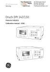
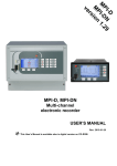
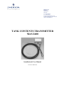
Damcos A/S
Boeletvej 1
DK-8680 Ry
Denmark
T +45 5578 7200
F +45 8689 2280
E [email protected]
W www.emersonprocess.com/mtm
CVR no. DK49698119
TANK CONTENTS TRANSMITTER
MAS 2600
Installation & User Manual
Version 11UK-09.09
Table of contents
Description and Operation ............................................................................................. 3
MAS 2600 Tank Contents Transmitter .............................................................................................3
Application.........................................................................................................................................3
Intrinsically Safe in Hazardous Areas ...............................................................................................3
Type Approvals .................................................................................................................................3
Technical Specifications ................................................................................................ 4
MAS 2600 Ordering Information .................................................................................. 5
Type ...................................................................................................................................................6
Measuring Ranges .............................................................................................................................6
Selecting the Measuring Range .....................................................................................................7
Selecting the Transducer Type ......................................................................................................7
Absolute Transducers ....................................................................................................................8
Basic Rules ....................................................................................................................................8
Forepeak Tank ...............................................................................................................................8
Draft ...............................................................................................................................................9
Temperature Sensor ...........................................................................................................................9
Cable ..................................................................................................................................................9
Brackets for Internal Mounting - drawing no. G022P010 ......................................................... 10
Pole Mounting - drawing no. G022P011 ................................................................................... 10
1” Pipe End Mounting - drawing no. G022P015 ....................................................................... 11
Flange Mounting - drawing no. G022P013................................................................................ 11
Flexible rubber tube mounting 80 .............................................................................................. 12
Flexible PTFE tube mounting .................................................................................................... 12
DN25 flange with 1” ball valve – drawing no. G022P019 ........................................................ 13
Amplifier Box ................................................................................................................................. 14
Amplifier PCB ................................................................................................................................ 15
Handling ....................................................................................................................... 16
Installation .................................................................................................................... 17
Intrinsically Safe Installation ....................................................................................... 19
Testing and Recalibrating ............................................................................................ 21
Testing............................................................................................................................................. 21
Recalibrating Gauge Transmitter using Test Cup type G022S100................................................ 21
Recalibrating Gauge Transmitter using Vacuum (for gauge transmitters only)............................ 22
Recalibrating the Absolute Transmitter using Test Cup type G022S100...................................... 23
Maintenance and Trouble Shooting ............................................................................. 25
Maintenance .................................................................................................................................... 25
Trouble Shooting ............................................................................................................................ 25
MAS2600 Test sheet ...................................................................................................................... 26
Page 2 of 26
Description and Operation
MAS 2600 Tank Contents Transmitter
The MAS 2600 is a 2-wire 4-20 mA level
transmitter consisting of a transducer and an
amplifier interconnected by a 6-core vented
cable.
Transducer:
The transducer is a pressure sensitive silicon
micro strain gauge sensor mounted in a glass
to metal seal. The sensor is protected by an
isolation diaphragm, electron beam welded
to the transducer housing, with an oil filling
between the sensor and the diaphragm.
Pressure changes on the front of the
diaphragm will bring a resistance change in
the Wheatstone bridge of the transducer.
This change in the Wheatstone bridge will
be transmitted to the amplifier as a change in
the electrical signal.
The transducer is fully welded, housed in
titanium with a titanium diaphragm.
• Fixed version: Calibration is done by
means of a computer system, e.g. tank
monitoring software.
• Differential version: For measuring of
both pressure and vacuum measuring.
Calibration is done by a computer system,
e.g. tank monitoring software.
The amplifier is housed in a sea water
resistant polyester casing (IP56).
Application
The MAS 2600 has been developed for level
measuring in ballast, oil, service and fresh
water tanks as well as tanks containing
media which are not hostile to titanium.
Intrinsically Safe in Hazardous Areas
The MAS 2600 is DEMKO approved for use
with standard transmitter zener barriers or
Ex isolation amplifiers and is EEx ia IIC T5
compliant in accordance with CENELEC
EN 50020.
All transducer types are submersible (IP68).
The transducer is available in three versions:
• Gauge version.
• Absolute version.
• High temperature gauge version.
Type Approvals
DNV, GL, LRS, MRS, BV, RINA, NK,
PRS, KRS, ABS, MSA.
CE marked in accordance with EU directive.
As optional the transducer is available with a
built-in Pt100 temperature sensor.
2600 SERIES
Amplifier:
The amplifier is available in the following
options:
4- 20 mA
x
EEX ia
CERTIFICATE REF.:
Lint = 20 uH
• Programmable version: Calibration is
made by dip switches and potentiometers.
TWO WIRE TRANSMITTER
C T5 S/ N: 2600
90- C.95948 Tamb.:
Cint = 10 nF
Umax = 33 V
- 40 to +85 ° C
< 45 mA
IK =
MARINE AUTOMATION DENMARK
DMS
MAS 2600
PDCR- 941- 1
1.5 bar g
S/ N 46374
Transduce
Amplifier box
Page 3 of 26
Technical Specifications
Output Current:
4-20 mA DC, loop powered 2-wire system.
Transducer Ranges:
Gauge: 0-3.5 / 0-7 / 0-16 / 0-35 m H2O.
Absolute:
0-20.394 / 0-35.690 m H2O.
Current Limiting:
Max:
25 mA
Programmable Measuring Ranges:
Each transducer range is programmable in 8
steps.
Sensor Materials:
Housing: Titanium Grade 2
Diaphragm: Titanium Grade 4
Accuracy:
± 0.25% F.S. at 20°C.
Operating Temperature Ranges:
Transducer:
-20 to +125°C
Standard cable:
-20 to + 80°C
High temperature cable:
-20 to +125°C
Amplifier:
-40 to + 85°C
Overload Capability:
Min. 4 x transducer range with no changes in
calibration.
6 x transducer range burst pressure.
Built-in Temperature Sensor Pt100:
Optional.
Power Supply:
The Power Supply can vary from 14-33
VDC. Permissible load resistance is shown
graphically below. Calculation formula:
Protection Class:
Transducer:
Amplifier:
IP 68
IP 56
Intrinsic Safety:
EEx ia IIC T5 compliant.
Max. 75 m cable between transducer and
transmitter amplifier.
Transmitter dimensions
Amplifier box:
110.0
55.0
98.0
2600 SERIES
4- 20 mA TWO WIRE TRANSMITTER
x
EEX
ia
C T5
S/ N:
CERTIFICATE REF.: 90- C.95948 Tamb.:
Lint = 20 uH
Cint = 10 nF
Umax = 33 V
2600
- 40 t o +85 ° C
4 pcs. ø4.5
45.0
TEB (Total Error Band):
± 2.0% F.S. at -20 to +80°C.
75.0
Stability:
Max. ± 0.1% / Year.
< 45 mA
IK =
MARINE AUTOMATION DENMARK
ULoop - 14V
Rloop max. (Kohm) =
32 mA
PG11
cable gland
1/8" NPT
vent fitting
800
600
400
200
0
3.0
14 17 20 23 26 29 32
Power supply (V)
Page 4 of 26
Transducer:
6-core vented cable, ø8.0
25.0
30.0
Load resistance
(ohm)
Max. load resistance
at various power supply
Use 4x20mm bolts and nuts
for suspension on a 4mm
thick surface
120.0
Front view
MAS 2600 Ordering Information
Type
A
absolute transducer
G
gauge transducer
H
high temperature gauge transducer
Transducer Ranges
1 3,5 mH2O gauge or high temp.
2 7,0 mH2O gauge or high temp.
3 16,0 mH2O gauge or high temp.
4 35,0 mH2O gauge or 0,8 – 3,5 bar absolute
7 0,8 – 2,0 bar absolute
Temperature Sensor
0 without
1 Built-in Pt100
Cable
XX XLPE standard cable length in meters (up to 80°C). Max. 300 meters
XX FEP high temperature cable length in meters (up to 125°C). Max. 300
meters
Mounting
0
without fittings
1
brackets for internal mounting
2
pole mounting
3
1" pipe end mounting
4
flange mounting DN 25
5
flange mounting DN 40
6
flange mounting DN 50
9
flexible rubber tube mounting – 80 ºC (add length in meters)
P
flexible PTFE tube mounting – 125 ºC (add length in meters)
V
DN25 flange / 1” ball valve
A-M
replacement
Amplifier Box
0 not supplied
1 standard box with PG 11 / PG 11
2 standard box with PG 11 / PG 13,5
3 standard box with PG 11 / PG 16
4 silumin box type 2600 box-alu
5 standard box with PG 13,5 / PG 13,5
6 standard box with PG 11 / PG 11 – filling hole
7 standard box with PG 11 / PG 13,5 – filling hole
8 standard box with PG 11 / PG 16 – filling hole
Amplifier PCB
0
not supplied
without terminals for temperature sensors:
P
programmable output range gauge
D
differential output range gauge
with terminals for temperature sensors:
S
programmable output range gauge
M differential output range gauge
X
X
X - XX -
X
/ X X
Page 5 of 26
Type
MAS 2600-XXX-XX-X/XX
A: Absolute Transducer. The absolute transducer has no breather pipe, because it refers to
absolute vacuum. An atmospheric pressure sensor is used to compensate for the atmospheric
pressure. The absolute transducer is especially suitable for open deck applications, where the
amplifier box may be exposed to flooding.
G: Gauge Transducer. The gauge transducer is fitted with a breather pipe at the back of the
diaphragm to compensate for the atmospheric pressure. The breather pipe is connected to a
vent plug in the amplifier box. The gauge transducer is suitable for most applications.
H: High Temperature Transducer. The high temperature transducer is available in gauge version
only. The transducer is mounted with a special high temperature cable and designed for
heated tanks e.g. HFO tanks, and other applications with high tank media temperatures. The
transducer can be flange mounted or internally mounted.
Measuring Ranges
MAS 2600-XXX-XX-X/XX
Gauge Transmitter:
The MAS 2600 Gauge Transmitter is supplied in 4 ranges. In the programmable amplifier the
measuring range is divided into 8 sub-ranges and operated by means of the range select switch.
The transmitter output signal can be adjusted to 20 mA within the following sub-ranges.
Transducer type
Range No.
Type 1:
0 – 3.5 mH2O
Type 2:
0 – 7.0 mH2O
Type 3:
0 – 16.0 mH2O
Type 4:
0 – 35.0 mH2O
1
0.20 – 0.37 mH2O
0.20 – 0.30 mH2O
0.50 – 0.75 mH2O
1.00 – 1.90 mH2O
2
0.37 – 0.54 mH2O
0.30 – 0.50 mH2O
0.75 – 1.00 mH2O
1.90 – 2.80 mH2O
3
0.54 – 0.73 mH2O
0.50 – 0.70 mH2O
1.00 – 1.50 mH2O
2.80 – 3.90 mH2O
4
0.73 – 1.10 mH2O
0.70 – 1.10 mH2O
1.50 – 2.50 mH2O
3.90 – 5.80 mH2O
5
1.10 – 1.92 mH2O
1.10 – 1.80 mH2O
2.50 – 4.00mH2O
5.80 – 9.90 mH2O
6
1.92 – 3.10 mH2O
1.80 – 3.00 mH2O
4.00 – 6.00 mH2O
9.90 – 15.30 mH2O
7
3.10 – 3.50 mH2O
3.00 – 4.80 mH2O
6.00 – 10.00 mH2O
15.30 – 25.10 mH2O
8
NOT
APPLICABLE
4.80 – 7.10 mH2O
10.00 – 16.00 mH2O 25.10 – 35.60 mH2O
Page 6 of 26
Absolute Transmitter:
The MAS 2600 Absolute Transmitter is available in two ranges.
The output signals are calibrated as follows:
Transducer type 4
Transducer type 7
: 0.8 - 3.5 bar abs
: 0.8 - 2.0 bar abs
Selecting the Measuring Range:
When selecting the measuring range it is important to consider the tank height, vent pipe height,
the tank type and the specific gravity (SG) of the tank contents.
The transducer measures the height of the fluid (water gauge) from the transducer diaphragm to
the surface of the fluid, including the fluid in the vent pipe.
MAS 2600 Amplifier box
2600 SERIES
4- 20 mA TWO WIRE TRANSMITTER
x
EEX ia C T5 S/ N: 2600
CERTIFICATE REF.: 90- C.95948 Tamb.:
- 40 to +85 ° C
Lint = 20 uH
< 45 mA
IK=
Cint = 10 nF Umax = 33 V
MARINE AUTOMATION DENMARK
Vent pipe height
Tankheight
Flange mounted
G022P013
Sensor pos. above
lowest point
To ensure measuring accuracy a transducer type within the range no. 4, 5, 6, 7 and 8 is
recommended.
Guidelines for selection of transducer measuring ranges are set out in the following.
Selecting the Transducer Type:
Gauge and High Temperature Gauge Transducers:
The Gauge Transmitter is normally used on dry and pressure neutral locations.
The Gauge Transmitter is available in 4 ranges:
0-3.5
0-7.0
0-16.0
0-35.0
mH2O.
mH2O.
mH2O.
mH2O.
Page 7 of 26
Absolute Transducers:
The Absolute Transmitter is typically used if the amplifier is exposed to water, e.g. on open deck.
The Absolute Transmitter is available in 2 ranges: 0-20 and 0-35 mH2O. In practice this means 10
mH2O less than the nominal range because of the atmospheric pressure which must be taken into
consideration when choosing the transducer.
A transducer with an effective range larger than the tank height should be selected.
Basic Rules:
1. The selected measuring range must be larger than the tank height.
2. The selected measuring range must be larger than
EXAMPLE:
tank height + vent pipe height
2
Tank height
= 6m
Vent pipe height = 14 m
1. The selected measuring range must be larger than 6 m due to the height of the tank.
6 + 14
2. The selected measuring range must be lager than
= 10 m due to the total height of the
2
tank and the vent pipe combined.
Select a transducer with a measuring range of 16 mH2O as this is the next measuring range larger
than 10 m.
Turn the range select switch on the amplifier to range No. 7.
Normally the selection of transducer, range select and calibration are done by DAMCOS.
Special consideration applies to e.g. forepeak tanks and draft measuring when selecting the
measuring range of the transducer.
Forepeak Tank:
Transducer measuring range > tank height: Select the next measuring range.
EXAMPLE: Tank height 12 m.
Based on the tank height a transducer with a measuring range of 16 mH2O should be selected.
However, due to the dynamic conditions in the forepeak tank, a transducer with a measuring
range of 35 mH2O, i.e. the next in line, should be selected.
Turn amplifier range select switch to range No. 6.
Page 8 of 26
Draft:
Vent pipe min. 1”
MAS 2600 amplifier
b
2600 SERIES
4- 20 mA TWO WIRE TRANSMITTER
x
C T5 S/ N: 2600
EEX ia
CERTIFICATE REF.: 90- C.95948 Tamb.:
Lint = 20 uH
Weather deck
Cint = 10 nF
Umax = 33 V
- 40 to +85 ° C
< 45 mA
IK =
MARINE AUTOMATION DENMARK
Min. draft
Sensor pos. above
Ships hull
Class approved
Sea valve
Ships hull
Transducer measuring range > max. draft minus sensor position.
This rule applies provided the transducer is mounted in accordance with the installation drawing
for draft transmitters (vent pipe min. 1").
If the transducer is installed in tanks which may have excessive dynamic stresses such as e.g.
high pump pressure, long bottomed tanks with a risk of slashing etc., contact Emerson Process
Management Marine Solutions, Damcos.
Temperature Sensor MAS 2600-XXX-XX-X/XX
The transducer can be supplied with a built-in Pt100 temperature sensor. The temperature sensor
will only give a proper reading, if the transducer is an internally mounted type.
0:
1:
Without temperature sensor.
With temperature sensor
Cable MAS 2600-XXX-XX-X/XX
Two types of transducer cable is available. The standard cable for applications with temperatures
never exceeding 80°C, and high temperature cable for applications with temperatures up to
125°C. The transducer cable is delivered in whole meters.
For further information require data sheet.
To make the MAS 2600 transmitter easy to install, and for later service purposes, the transducer
cable should be as short as possible, though considering the position of the transducer and
amplifier box.
Max. cable length: 300 m.
When installing in hazardous areas max. cable length: 75 m.
Page 9 of 26
Brackets for Internal Mounting - drawing no. G022P010:
2600 SERIES
4- 20 mA TWO WIRE TRANSMITTER
x
EEX ia C T5 S/ N: 2600
CERTIFICATE REF.: 90- C.95948 Tamb.:
Lint = 20 uH
Cint = 10 nF
Umax = 33 V
- 40 to +85 ° C
< 45 mA
IK=
MARINE AUTOMATION DENMARK
40.0
55.0
38.0
Tank top
Bulkhead
125.0
45.0
160.0
Tank bottom
The brackets are U-shaped and manufactured of 2 mm SS 316L plated steel. Diameter of
mounting holes: 11.5 mm.
The transducer is secured by means of a spring fitted into two holes in the “U” shape, and can be
mounted/dismounted without the use of tools.
Pole Mounting - drawing no. G022P011:
2600 SERIES
4- 20 mA TWO WIRE TRANSMITTER
x
EEX ia C T5 S/ N: 2600
CERTIFICATE REF.: 90- C.95948 Tamb.:
- 40 to +85 ° C
Lint = 20 uH
< 45 mA
IK=
Cint = 10 nF
Umax = 33 V
MARINE AUTOMATION DENMARK
Tank top
24.0
40.0
41.0
26.0
34.0
Tank bottom
26.0
Bulkhead
1" Thread
The weldable collar and the nut are manufactured of SS 316L steel. The gaskets are made of
nitrile rubber.
Note: Max torque 20 Nm (slightly tighten by the hand + 1/8-1/4 turn). Remember the gasket.
Page 10 of 26
1” Pipe End Mounting - drawing no. G022P015:
2600 SERIES
4- 20 mA TWO WIRE TRANSMITTER
x
C T5 S/ N: 2600
EEX ia
CERTIFICATE REF.: 90- C.95948 Tamb.:
Lint = 20 uH
Cint = 10 nF Umax = 33 V
- 40 to +85 ° C
< 45 mA
IK=
MARINE AUTOMATION DENMARK
80,0
55,0
24.0
25,0
41,0
26,0
26,0
34.0
Tank top
Bulkhead
Tank bottom
The thread collar and the nut are manufactured of SS 316L steel. The gaskets are made of nitrile
rubber.
Note: Max torque 20 Nm (slightly tighten by the hand + 1/8-1/4 turn). Remember the gasket.
Flange Mounting - drawing no. G022P013:
b
2600 SERIES
4- 20 mA TWO WIRE TRANSMITTER
x
C T5 S/ N: 2600
EEX ia
CERTIFICATE REF.: 90- C.95948 Tamb.:
Lint = 20 uH
Cint = 10 nF Umax = 33 V
- 40 to +85 ° C
< 45 mA
IK=
d
MARINE AUTOMATION DENMARK
k
19,5
D
Tank top
Bulkhead
Tank bottom
The standard transducer is supplied with DN25, DN40 or DN50 PN16 DIN2527 flange
manufactured in AISI 316L steel.
DN
25
40
50
D
Mm
115
150
165
Flange
B
mm
16
16
18
K
Mm
85
110
125
No. of
bolts
4
4
4
Bolts
thread
dia.
M12
M16
M16
d
mm
14
18
18
Note: Max torque 20 Nm (slightly tighten by the hand + 1/8-1/4 turn). Remember the gasket.
Page 11 of 26
Flexible rubber tube mounting 80 ºC - drawing no. G022P001:
2600 SERIES
4- 20 mA TWO WIRE TRANSMITTER
x
EEX ia C T5 S/ N: 2600
CERTIFICATE REF.: 90- C.95948 Tamb.:
- 40 to +85 ° C
Lint = 20 uH
< 45 mA
IK =
Cint = 10 nF
Umax = 33 V
MARINE AUTOMATION DENMARK
Tank top
H
Bulkhead
Tank bottom
A top flange made of SS 316L connected to rubber tube by a tightening clip using a special tool.
The opposite hose end covers the transducer body and is fixed by a tightening clip.
NB: When ordering this mounting type always specify length for the measurement of H
cf. above drawing.
Flexible PTFE tube mounting 125ºC - drawing no. G022P021:
2600 SERIES
4- 20 mA TWO WIRE TRANSMITTER
x
EEX ia C T5 S/ N: 2600
CERTIFICATE REF.: 90- C.95948 Tamb.:
- 40 to +85 ° C
Lint = 20 uH
IK <
= 45 mA
Cint = 10 nF
Umax = 33 V
MARINE AUTOMATION DENMARK
Tank top
H
Bulkhead
Tank bottom
A top flange made of SS 316L connected to a Stainless Steel braided PTFE tube by fittings fixed
to the tube by using special tools. A fitting in the opposite tube end is fixed to the transducer by
means of nut and ferrules. Min. hose bending radius 130 mm.
NB: When ordering this mounting type always specify length for the measurement of H
cf. above drawing.
Note: This mounting type can only be assembled by Emerson Process Management Marine
Solutions, Damcos because it requires special tools. The customer can exchange the MAS 2600
transmitter by ordering a G022B085 and a G022B082 together with the new MAS 2600
transducer. It must clearly be specified that it is a replacement for an MAS 2600 HXX-XX-P/XX.
Page 12 of 26
DN25 flange with 1” ball valve – drawing no. G022P019:
2600 SERIES
4- 20 mA TWO WIRE TRANSMITTER
x
C T5 S/ N: 2600
EEX ia
CERTIFICATE REF.: 90- C.95948 Tamb.:
- 40 to +85 ° C
Lint = 20 uH
IK <
= 45 mA
Cint = 10 nF Umax = 33 V
MARINE AUTOMATION DENMARK
Tank top
Bulkhead
Tank bottom
Flange, valve and nut are manufactured of SS 316L steel. The gaskets are made of nitrile rubber.
Note: Max torque 20 Nm (slightly tighten by the hand + 1/8-1/4 turn). Remember the gasket.
Page 13 of 26
Amplifier Box
MAS 2600-XXX-XX-X/XX
The MAS 2600 amplifier box is manufactured in polyester, which has the strength and stability of
aluminium, insulation and resistance properties of plastics. Colour code RAL 7000.
The amplifier box is protected to the level of IP 56 and must be mounted outside the tank, e.g. in
the engine room or other dry areas.
The amplifier box is available with a PG9 hole for silicone gel filling to protect the amplifier
from moisture.
If the amplifier box is mounted on open deck with the risk of being over floated it is
recommended to mount the amplifier box inside the special DAMCOS deck box made of
stainless steel. For more information please contact DAMCOS.
0: Without amplifierbox.
1: Standard box with PG 11 / PG 11 cable glands. For cables with a diameter up to ø11.0.
2: Standard box with PG 11 / PG 13.5 cable glands. For cables with a diameter up to ø13.5.
3: Standard box with PG 11 / PG 16 cable glands. For cables with a diameter up to ø16.0.
4: Silumin box.
5: Standard box with PG 13.5 / PG 13.5 cable glands. For cables with a diameter up to ø13.5.
6: Standard box with PG 11 / PG 11 cable glands and filling hole. For cables with a diameter up
to ø11.0.
7: Standard box with PG 11 / PG 13.5 cable glands and filling hole. For cable with a diameter
up to ø13.5.
8: Standard box with PG 11 / PG 16 cable glands and filling hole. For cable with a diameter up
to ø16.0.
110.0
55.0
98.0
EEX
ia
C T5
S/ N:
CERTIFICATE REF.: 90- C.95948 Tamb.:
Lint = 20 uH
Cint = 10 nF
Umax = 33 V
2600
4 pcs. ø4.5
- 40 t o +85 ° C
75.0
x
< 45 mA
IK =
MARINE AUTOMATION DENMARK
PG11
cable gland
1/8" NPT
vent fitting
Page 14 of 26
Use 4x20mm bolts and nuts
for suspension on a 4mm
thick surface
45.0
2600 SERIES
4- 20 mA TWO WIRE TRANSMITTER
Amplifier PCB
MAS 2600-XXX-XX-X/XX
The PCB is available in different types for the different transducers, with or without terminals for
Pt100 temperature sensor.
0:
Without amplifier PCB.
P or S: Programmable output range. The amplifier can be calibrated to 4-20 mA output in
whatever range wanted within the transducer range. Calibration is made by means of dip
switches and potentiometers.
D or M: Differential output range. The output can be adjusted to 12 mA output with no pressure
applied. With pressure or vacuum, the output goes against 20 mA and 4 mA
respectively. Full-scale and zero point calibration by means of software, e.g. tank
monitoring software.
• The types S and M are with terminals for temperature sensors.
• The types P and D are without terminals for temperature sensors.
Programmable Range (Type P)
Programmable Range (Type P)
Page 15 of 26
Handling
The MAS 2600 transducer is a highly sensitive electronic piece of equipment and proper handling
is most important.
To avoid damaging the transducers:
• NEVER lift by the cable if transducer is mounted with fittings.
• NEVER remove the protection cap in front of the diaphragm before installation.
• NEVER knock the transducer.
• NEVER apply pressure to the diaphragm in any way whatsoever, whether using fingers, tools
or sharp objects.
• NEVER use sharp objects when cleaning the diaphragm.
• NEVER submerge the cable so that the breather tube is under water.
• NEVER bend the cable in a radius of less than 90 mm.
Page 16 of 26
Installation
Prior to installation please check that:
• the serial numbers on the transducer, amplifier and lid of amplifier box agree. The serial
numbers are to be found on the inside of the lid of the amplifier box on the bottom line amplifier S/N and transducer S/N on the range label.
• the transducer is fitted in the correct tank.
• the transducer is correctly connected to the amplifier.
NOTE: The white and brown wires in the transducer cable are only used when a Pt100 sensor
is built into the transducer.
• all cable glands are properly secured to the amplifier box.
• the amplifier box is mounted in such a way that the breather tube cannot be flooded.
• the cable is fastened with cable clips with a distance of max. 50 cm.
• the cable isolation is not damaged (cracks, weld spatter, burns etc.).
• shut-off valves can be either ball valves or other valves not generating over pressure exceeding
4 x the transducer range between valve seat and transducer when the valve is closed.
As for flange mounted applications it is recommended that a ball valve is fitted in the front of the
transducer to facilitate testing and calibrating of the transmitter.
Using a shielded cable to the 4-20 mA signal, the shield should not be connected in the amplifier
box but the earth terminal of the instrument.
Using a shielded cable ensures maximum protection against electric noise.
Page 17 of 26
If the amplifier box is installed in an area with over pressure or negative pressure in relation to
the atmospheric pressure in the tank, the breather tube must be directed to an area with
atmospheric pressure equalling the pressure inside the tank. This applies to gauge transmitters
only. For absolute transmitters this has no affect, due to the reference to absolute vacuum and not
atmospheric pressure. This is also the reason why no breather tube is necessary.
Shield bracket
Do not fasten to tight
Transducer cable
Breather tube
1/8” NPT fitting
for breather tube
Terminal block for Pt100
element
Page 18 of 26
Breather hose
4-20 mA signal cable
Intrinsically Safe Installation
The MAS 2600 is designed for use in an approved intrinsically safe installation. The amplifier is
fitted with a label describing the IS category:
EEx ia IIC T5
Tamb. = -40 to +85 °C
where
E
:
denotes the harmonised European Standard (CENELEC).
Ex ia :
denotes the category of intrinsic safety, i.e. the system is incapable of causing ignition
in normal operation or with any combination of up to two faults applied. This
category will be adequate for use in zone 0, 1 and 2.
IIC
:
T5
:
denotes the group of gases or vapours, e.g. hydrogen (detailed description in EN 50
020).
denotes the maximum surface temperature classification specified (T5: 100 °C).
Tamb :
denotes the minimum and maximum ambient temperature permitted by the certificate.
Relevant intrinsic safety certificates to be supplied with the system units.
The certification of electric apparatus as intrinsically safe requires the apparatus to be designed
and tested in accordance with approved drawings and the apparatus to be installed in accordance
with approved block schematic diagrams.
Before installing intrinsically safe units within an approved installation, it is essential to ensure
that there are no deviations from the conditions of the order or the requirements of the approved
block schematic diagram and the following related instructions:
1.
No circuits other than those shown on the drawing are permitted. There must be no
interconnection to any other circuits.
2.
The intrinsically safe cabling must not be connected to non-intrinsically safe circuits,
through any plug, socket or other form of electric connector containing the cable.
3.
Adequate precautions must be taken to prevent danger arising from the charging of the
intrinsically safe circuit by the contact leakage or inductance from any other circuit.
4.
The intrinsically safe circuit must be adequately insulated from earth in the hazardous area
and the insulation of all cabling must be at least 500 V r.m.s.
5.
The safety barrier (zener barrier) must be placed in a safe area and be mounted within a
protective enclosure with a protection degree, at least equal to IP 20.
Page 19 of 26
6.
The cable between the safety barrier and the amplifier should be provided with a cable
shield which is connected to earth at the zener barrier. The impedance between the safety
barrier earth rail and a secure bond to the hull must not exceed 1 ohm.
7.
Safe area apparatus must not be supplied from, nor contain, a source of potential with
respect to earth under normal or abnormal conditions exceeding 250V r.m.s. or 250 V d.c.
8.
The inductance/resistance ratio, total inductance and total capacitance, of the cable must
not exceed the values stated by the manufacturer of the approved safety barriers.
Reference is made to manufacturer instructions of zener barriers and to the rules in force at the
time in question concerning intrinsically safe area installation.
Hazardous area
Safe area
Indication by simple gauge
or tankmonitoring computer
m3
Amplifier box
2600 SERIES
+
24 VDC
Any 28V / 300R
Shunt zener diode safty
barrier or Ex repeater
certified to Ex Ia IIC.
4- 20 mA TWO WIRE TRANSMITTER
x
4-20 mA
+
EEX
ia
C T5
S/ N:
CERTIFICATE REF.: 90- C.95948 Tamb.:
Lint = 20 uH
Cint = 10 nF
Umax = 33 V
- 40 t o + 85 ° C
IK <
= 45 mA
MARINE AUTOMATION DENMARK
4-20 mA
Transducer
Page 20 of 26
2600
Testing and Recalibrating
Testing
Before dispatch, the MAS 2600 transmitter is calibrated in accordance with the requirements
specified in the order.
The transducer and the amplifier are calibrated together and must, therefore, always be used
together.
A programmable measuring range transmitter will in conditions of no pressure (empty tank) give
an output signal of 4 mA, and in conditions of maximum pressure (full tank) an output signal of
20 mA.
The transmitter should be tested by applying to the transducer a known pressure from a calibrator
and reading the equivalent milliampere signal on a milliampmeter.
The above-mentioned applies to the gauges transmitter only. For absolute transmitters the output
signal will be higher than 4 mA, because it is calibrated for 4 mA at 0.8 bar abs. The output
signal will typically be 5-7.5 mA in atmospheric pressure, depending on the transducer range and
the actual atmospheric pressure. Maximum output signal 20 mA, will be at the transducers
absolute range.
Recalibrating Gauge Transmitter using Test Cup type G022S100
When recalibrating the MAS 2600 Gauge Transmitter a pressure calibrator with a range of
-1 to 3.5 bar should be used. It should have an accuracy of 0.05% FS or better, as well as a 4½
digit milliampmeter.
1.
Set the calibrator to pressure mode.
2.
Connect the pressure calibrator to the transducer via MAS 2600 Test Cup, type G022S100.
3.
Check that the range select switch on the amplifier is correctly set.
4.
In conditions of no pressure (atmospheric pressure) the output signal should be adjusted to
4.00 mA on the zero potentiometer.
5.
Increase the pressure to maximum and adjust the output signal to 20.00 mA on the span
potentiometer.
6.
Remove the pressure and check the zero point
7.
Check the linearity at 0-25-50-75 and 100% of the measuring range.
8.
If necessary, repeat the steps 4 to 7.
NOTE:
If there is no zero and span potentiometer, the unit is a ‘fixed measuring range’
unit. This unit cannot be calibrated.
Page 21 of 26
Recalibrating Gauge Transmitter using Vacuum (for gauge transmitters only)
An internally mounted transducer can also be recalibrated by using vacuum.
1.
Check that the tank is empty.
2.
Check that the range select switch on the amplifier is correctly set.
3.
Set the calibrator to vacuum mode.
4.
Connect the hose from the calibrator to the breather tube from the transducer cable.
5.
In conditions of no pressure the output signal should be adjusted to 4.00 mA on the zero
potentiometer.
6.
Increase the vacuum equal to the maximum height of the fluid (water gauge) and adjust the
output signal to 20.00 mA on the span potentiometer.
7.
Remove the vacuum and check the zero point.
8.
Check the linearity at 0-25-50-75 and 100% of the measuring range.
9.
If necessary, repeat the steps 5 to 8.
NOTE:
If the calibrated maximum water gauge is greater than the maximum water gauge
that can be generated by the vacuum calibrator, the proportional mA output signal
equal to the maximum vacuum signal should be calculated.
EXAMPLE: If the full-scale of the transmitter is 15 mH2O, and the maximum capacity of the
vacuum calibrator is 7.5 mH2O, the mA output signal at 7.5 mH2O is calculated as:
15 mH2O = 20 mA and 0 mH2O = 4 mA
7.5 mH2O = 4 +
(20 − 4) * 7.5
= 12 mA
15
The span potentiometer is adjusted so that the output signal shows 12 mA at 7.5 mH2O.
Page 22 of 26
Recalibrating the Absolute Transmitter using Test Cup type G022S100
When recalibrating the MAS 2600 Absolute Transmitter a pressure calibrator with a range of
-1 to 3.5 bar should be used. It should have an accuracy of 0.05% FS or better, as well as a 4½
digit milliampmeter. If a calibrator without reference transmitter is used, the atmospheric pressure
must be known to calculate the correction.
Atmospheric pressure and Transducer range to be entered into the formulas as mbar.
1.
The calibrator with the output selector switch set to pressure mode is connected to the
MAS 2600 transmitter via a Test Cup, type G022S100.
2.
Check the transducer range.
The transducer range is indicated on the lid inside the amplifier box.
3.
Calculate output signal in conditions of no pressure (atmospheric pressure), using
formula. The output signal should be adjusted to the calculated value on the
zero
potentiometer.
16 *( Atm. press − 800)
mA @ Atmospheric pressure = 4 +
Trd . range − 800
4.
bellow
Calculate the pressure for maximum output signal, using the following formula.
mbarg @ 20 mA = Trd . range − Atm. press
Increase the pressure to calculated pressure and adjust the output signal to 20.00 mA on the
span potentiometer.
5.
Remove the pressure and check the zero point.
6.
Check the linearity at 0-25-50-75 and 100% of the measuring range.
Output signal at different pressures P can be calculated, using the following formula.
mA @ P mbarg = 4 +
7.
16 *( Atm. press − 800 + P)
Trd . range − 800
If necessary, repeat the steps 3 to 6.
Page 23 of 26
EXAMPLE: If the range of the transducer is 3.5 bar abs and the atmospheric pressure is
1005 mbar.
Calculated output at atmospheric pressure:
mA @ Atm.press = 4 +
16 * (1005 − 800)
= 5.215 mA
3500 − 800
Calculated applied pressure for maximum output:
mbarg @ 20 mA = 3500 − 1005 = 2495 mbarg
Calculated pressure at 50% of the transducer range:
mA @ P mbarg = 4 +
Page 24 of 26
16 *(1005 − 800 + 1750)
= 15.585 mA
3500 − 800
Maintenance and Trouble Shooting
Maintenance
Damcos recommends that the following to be checked annually:
1.
Visual inspection of the cable, transducer and amplifier.
2.
Compare signal with e.g. hand sounding, and if necessary perform a zero and full-scale
calibration.
Trouble Shooting
If the MAS 2600 transmitter is not functioning in accordance with Emerson Process Management
Marine Solutions, Damcos instructions, check that:
1.
the 24 VDC power supply has been correctly connected, and is between 14-33 VDC.
2.
the 4 - 20 mA output signal is functioning (compared with e.g. hand sounding).
3.
the transducer cable has been correctly fitted and the shield connected to the shield terminal
in the amplifier box.
4.
the diaphragm has not been damaged.
If this does not succeed, fill in the test sheet on page 27 and submit this to our Service department
fax no.: +45 5578 7272.
When contacting our Service department please specify the serial numbers of both transducer and
amplifier.
The test sheet will be examined to see whether it can be established that the transmitter is broken
or not.
When returning a defective MAS 2600 transmitter for repairs, please ensure that:
• The transducer diaphragm is protected against blows of any kind.
• Both the transducer and the amplifier are returned.
• A detailed description of the fault is enclosed.
Page 25 of 26
MAS2600 Test sheet
ATT.:
FAX.:
Emerson Process Management
Marine Solutions
Damcos A/S, Service Department
+45 5578 7272
Name:
Ship name:
Yard:
MAS2600:
Transducer serial no.:
Tank name:
Liquid in tank
HFO:
The tank is
Full:
Measurements:
1
2
3
4
5
6
7
8
Measure voltage between terminal
5 and 6
Measure ripple voltage between
terminal 5 and 6
Measure sensor excitation voltage
between terminal 7 and 10
Measure sensor excitation voltage
between terminal 8 and 9
Measure current in supply lead to
terminal 5
Measure current in supply lead to
terminal 6
Measure sensor resistance with
sensor cable unconnected
Terminal 7 to cable shield
Terminal 8 to cable shield
Terminal 9 to cable shield
Terminal 10 to cable shield
Measure sensor bridge resistance
with sensor cable unconnected
Terminal 7 to Terminal 8
Terminal 7 to Terminal 9
Terminal 7 to Terminal 10
Terminal 8 to Terminal 9
Terminal 8 to Terminal 10
Terminal 9 to Terminal 10
NB No:
Amplifier serial no.:
DO:
Ballast:
Empty:
V DC
V AC
V DC
mV DC
mA DC
mA DC
Voltage should be in the range 14 to 33 V DC.
Check power supply.
Voltage must not exceed 2 V AC. Check power
supply.
Voltage should be in the range 3.0 to 6.2 V DC
Voltage should be in the range -15 to 100 mV DC
Current should be in the range 4 to 20 mA and the
same value as measured in point 6. If not the
amplifier may be defect.
Current should be in the range 4 to 20 mA and the
same value as measured in point 5. If not the
amplifier may be defect.
If the resistance measured is less that 1 M Ohm the
sensor is defect.
M Ohm
M Ohm
M Ohm
M Ohm
If the resistance measured is less than 1 K Ohm or
greater that 50 K Ohm the sensor is defect.
K Ohm
K Ohm
K Ohm
K Ohm
K Ohm
K Ohm
9
Visual inspection of the transmitter:
Is the cable damaged?
Are there sharp bends on the cable?
Are there moisture/liquids in the breather tube?
Is the diaphragm damaged?
10
Comments:
Page 26 of 26
Other:
Other: