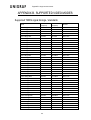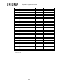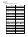
1
UFG-07 Family Frame Grabbers USER MANUAL Windows® 8 Windows® 7 Windows® XP About this Manual Copyright This manual, Copyright © 2013 Unigraf Oy. All rights reserved Reproduction of this manual in whole or in part without written permission of Unigraf Oy is prohibited. Notice The information given in this manual is verified in the correctness on the date of issue. The authors reserve the rights to make any changes to this product and to revise the information about the products contained in this manual without an obligation to notify any persons about such revisions or changes. Edition UFG-07 Family User Manual (Rev 3) Document identifier: Date: 09 January 2014 Company information Unigraf Oy Piispantilankuja 4 FI-02240 ESPOO Finland Tel. +358 9 859 550 mailto:[email protected] http://www.unigraf.fi 2. About this Manual Trademarks Unigraf and UFG are trademarks of Unigraf Oy. Windows® 7 and Windows® XP are trademarks of Microsoft Inc. All other trademarks are properties of their respective owners. Limited Warranty Unigraf warrants its hardware products to be free from defects in workmanship and materials, under normal use and service, for twelve (12) months from the date of purchase from Unigraf or its authorized dealer. If the product proves defective within the warranty period, Unigraf will provide repair or replacement of the product. Unigraf shall have the whole discretion whether to repair or replace, and replacement product may be new or reconditioned. Replacement product shall be of equivalent or better specifications, relative to the defective product, but need not to be identical. Any product or part repaired by Unigraf pursuant to this warranty shall have a warranty period of not less than 90 days, from the date of such repair, irrespective of any earlier expiration of original warranty period. When Unigraf provides replacement, then the defective product becomes the property of Unigraf. Warranty service may be obtained by contacting Unigraf within the warranty period. Unigraf will provide instructions for returning the defective product. CE Mark The UFG-07 Family frame grabbers meet the essential health and safety requirements, is in conformity with and the CE marking has been applied according to the relevant EU Directives using the relevant section of the corresponding standards and other normative documents. Please find a Declaration of Conformity attached to this document. 3. About this Manual Table of Contents 1. About this Manual ............................................................................................ 5 Purpose ........................................................................................................... 5 Product and Driver Version .............................................................................. 5 Notes ............................................................................................................... 5 2. Introduction ...................................................................................................... 6 Product Description ......................................................................................... 6 Product Features ............................................................................................. 6 Identifying Connectors ..................................................................................... 6 3. Installation........................................................................................................ 7 Unpacking ........................................................................................................ 7 Driver Type Selection ...................................................................................... 7 Driver Installation ............................................................................................. 8 Firmware Update ............................................................................................. 9 4. Configuration ................................................................................................. 10 Configuration Dialog ...................................................................................... 10 Input Source Type ......................................................................................... 10 RGB Input ........................................................................................... 11 DVI Input ............................................................................................ 12 S-Video and Composite Video............................................................ 13 Overriding Capture Format ............................................................................ 14 Adjusting Captured Colors ............................................................................. 15 Advanced Controls ........................................................................................ 16 Update Firmware ................................................................................ 16 Reset .................................................................................................. 16 A/D Converter Calibration ................................................................... 16 5. Usage ............................................................................................................ 17 Previewing Video ........................................................................................... 17 Capturing Video ............................................................................................. 17 Applications and Troubleshooting .................................................................. 18 GraphEdit ........................................................................................... 18 AmCap ............................................................................................... 18 Windows Media Encoder .................................................................... 18 VirtualDUB .......................................................................................... 18 Performance .................................................................................................. 19 Calculating the Requested Bandwidth ................................................ 19 Estimating the Bandwidth ................................................................... 19 Frame Locking .................................................................................... 20 Other Limitations ................................................................................ 20 Special registry setting ....................................................................... 20 Appendix A. Product Specification .................................................................................. 21 Analog Video Input ............................................................................. 21 Digital TMDS Video Input ................................................................... 21 S-Video and Composite Video Input................................................... 21 HW Features ...................................................................................... 21 Driver Properties................................................................................. 22 General ............................................................................................... 22 Appendix B. Supported Video Modes ............................................................................. 23 Supported TMDS signal timings / standards....................................... 23 Supported RGB signal timings / standards ......................................... 25 Supported YPbPr signal timings / standards ...................................... 26 4. About this Manual 1. ABOUT THIS MANUAL Purpose This guide is the User Manual of UFG-07 Family of Frame Grabbers for use in a PC with Windows® 8, Windows® 7 or Windows® XP operating system. The purpose of this guide is to Give an overview of the product and its features. Give instruction for the user on how to install the card. Give instructions for the user on how to install the related software drivers and libraries in a PC. Assist the user in configuring the capturing process with the user interface. Give instructions for the user how to capture images. Product and Driver Version This manual explains features found in product versions UFG-07 HS, UFG-07 Dual, UFG-07 HS Dual and UFG-07 STD Installation Package version 1.3; Driver version 1.3.3 (Firmware 3.0.1.14). Please consult Unigraf for differences or upgrades of previous versions. Notes On certain sections of the manual, when important information or notification is given, text is formatted as follows. Please read these notes carefully. Note This text is an important note 5. Introduction 2. INTRODUCTION Product Description UFG-07 Family board are PCI Express Frame Grabbers capable to capture digital HDMI and DVI, analog RGB and Component Video and also S-Video or Composite Video. The input video performance of the three models is equal; they differ mainly in the PCI bus interface. UFG-07 HS; PCI Express 4 lanes (mechanically 8 lane) UFG-07 HS Dual; PCI Express 8 lanes, 2 input channels UFG-07 Dual; PCI Express 4 lanes, 2 input channels UFG-07 STD; PCI Express 1 lane Product Features Captures video formats from 640 x 480 to 1920 x 1200. Top-down or bottoms up. Auto-detects VESA and CEA HDTV modes, supports CVT timings. High capture frame rates achieved by efficient on-board data handling and high speed bus interfaces (pls. refer to product specification for details). Optional frame locking (capture 1/1, 1/2, 1/3 or 1/4 of original frame rate) In Dual models two fully independent capturing channels, both of which can be HDMI / DVI, RGB / Component or Composite video. 64 and 32 bit AVStream drivers (x64, WOW64, X86) that are compatible with DirectShow compatible applications like Media Encoder, VLC, and VirtualDub. Supports Microsoft® 7 (32 and 64 bit) and Microsoft® XP (32 bit) Function to force default format change for applications that does not have advanced HD Stream Format Dialog Supports Power Management on Windows 7 and XP Identifying Connectors The UFG-07 HS and UFG-07 STD boards have three connectors on their front panel: S-Video connector for S-Video and Composite Video (top) DVI-I connector for digital HDMI and DVI input (middle) VGA connector (Sub-D 15) for analog RGB and Component Video (bottom) The UFG-07 HS Dual and UFG-07 HS Dual boards have three connectors on their front panel: S-Video connector for two Composite Video inputs (middle) Two DVI-I connectors for digital HDMI and DVI input and analog RGB and Component input (top and bottom) 6. Installation 3. INSTALLATION Unpacking The UFG-07 family frame grabber product shipment contains Note The UFG-07 card in an anti-static bag The Utilities CD containing drivers for Windows operating system along with ready to use sample Windows applications. An electronic copy of this User Manual is included. The UFG-07 boards are highly dedicated electronic devices that contain ESD sensitive components. Before opening the anti-static bag and always before touching the card, please be sure to ground yourself. You can do the grounding by wearing a special grounding strap or simply touching a grounded metal surface. Driver Type Selection The UFG-07 family supports Microsoft® 7 (32 and 64 bit) and Windows® XP (32 bit) operating systems. The Installation CD includes two alternative drivers: x64 drivers for 64 bit operating system x86 drivers for 32 bit operating systems The two drivers are located in separate folders in the installation CD. Please make sure that you select the proper one for your operating system and the application that you are using. 7. Installation Driver Installation Power down your PC. Insert UFG-07 card in a vacant PCI slot in your PC. Note: The hardware installation must be done before the software installation. Please use a PCI Express 1.0 slot. Note: Boot the Windows system and log in System administrator's privileges are required for performing the installation. The Plug and Play subsystem will detect the newly installed UFG-07 family board. In the Welcome to the New Hardware Wizard click Cancel. Please use the install.exe routine for pre-installation before the actual Windows installation. Open the folder containing the requested driver type included in the UFG-07 family Installation CD. Run install.exe application. Select Allow whenever the operating system prompts for permission. In the dialog click Install/Update. Press Continue and Apply whenever the operating system prompts for permission. Click Close when the installation is completed. The UFG-07 board is now ready for use. 8. Installation Firmware Update Please check the firmware version loaded into the non-volatile memory of the board. The firmware version must match to the driver version used. Open the Capture Filter Properties dialog of e.g. AmCap tool. Select FG Properties tab. The Advanced section of the dialog will indicate the mismatch between the firmware and the driver. If a mismatch exists, please click on Update Firmware button. If firmware is OK click No. If firmware does not match to the driver click Yes. Please note that the firmware update will take about three minutes. Note: For UFG-07 board to operate properly the driver and the firmware versions have to match. 9. Configuration 4. CONFIGURATION Configuration Dialog The parameters that describe the input source can be configured by the Capture Filter Properties dialog. The dialog contains three tabs: Windows standard Video Decoder tab, a Video Proc Amp tab and the FG Properties tab. All capture properties for UFG-07 can be configured through the FG Properties tab. The controls on the FG Properties panel are divided to five functionality sections. Please find below the description each section. Input Source Type You can select one of the four input types DVI/HDMI, RGB, Component, S-Video and Video with Input Source Type section. The Input Timing section provides slightly varying information for each of the three input types. When switching between the Input Source types the last valid values in the Picture panel settings are stored. 10. Configuration RGB Input The timing detection function measures the horizontal and vertical frequencies of the input signal and matches them to known standard timings and timing rules. It also detects the edges of the active video for correct positioning of the image. Clicking the Adjust button you can fine tune the positioning by re-detecting the image boundaries and the sampling phase. For best results of the positioning please consider the following rules: Please use a short and high quality video cable. Please use a still image during adjustment (no moving, flickering, etc.) Please use an image with light edges. Please use an image with sharp vertical edges e.g. black text over white background A spread sheet tool or a word processor program maximized to full screen will provide a good image for positioning 11. Configuration DVI Input DVI sources are set up automatically and they do not need any detection or calibration procedure. 12. Configuration S-Video and Composite Video S-Video and Composite Video (CVBS) sources are input through the S-Video Line-In. In the Input Source Type please select Video for Composite video and S-Video for SVideo type. The Input Timing section shows the detected source timing. Please find below a schema of the connection of Composite and S-Video signals to the RGB signal inputs of the DVI-I in UFG-07 Dual and the corresponding pins in a VGA connector for reference. 13. Configuration Overriding Capture Format The Fix Capture Format section is used for overriding capture frame size and frame rate that UFG-07 capture pin provides for the capturing application. By selecting the Override Resolution checkbox, the dimension selected in the combo-box or the X and Y fields will be forced for the capture pin even if the host application requests another format. The Apply button saves the custom values. You can frame lock to every 2nd, 3rd or 4th frame of the original video input to save PCI bus bandwidth and ensure a smooth video stream output. You can limit the captured frame rate to an arbitrary fps value You can control the image orientation when stored in the PC Note Frame Locking is designed to operate for progressive and interlaced sources with 60 Hz and 50 Hz vertical frequencies and field frequencies respectively. Note You will need over 20 fps capture speed for acceptable quality of moving objects. Please lock 60 Hz input video to 30 fps (SRC/2) or 20 fps FPS (SRC/3) and 50 Hz input video to 25 fps (SRC/2). You can have the UFG-07 output the captured bitmap flipped around vertically by selecting the Flip Vert. check-box. This means that the image is stored upside down. This is the default image for Windows® and some applications operate properly with this format. Please verify if your application accepts the state and leave it unchecked. Please note that Flip Vert. is only operational when Override Resolution is checked. 14. Configuration Adjusting Captured Colors The Picture section contains controls for adjusting the color information. Brightness, Contrast, Hue and Saturation have unique values for all three input types. The values are stored and re-loaded when the corresponding input is selected. The Reset button sets the factory default values. In most cases these values give an optimum result. Note: The Saturation control is only functional in Component, Composite and S-Video inputs. For RGB input you can additionally turn the captured image in Monochrome mode by sliding the ruler all the way to the left (Saturation = 0). In other positions the slider has no effect in RGB mode. 15. Configuration Advanced Controls The Advanced section contains controls for advanced features of the UFG-07 unit. The user might need the functions after the installation of the unit but not during the normal operation. Please use the features in this section with care. When done improperly, they may impair the correct operation of the UFG-07 unit. Update Firmware The on-board firmware version must match to the driver version used. If the firmware and the driver do not match, you will be requested to update the firmware. Firmware Update process is described in the Installation section earlier in this manual. Reset Repair Resets the UFG-07 unit. Not needed in normal operation. A/D Converter Calibration The A/D converter of the RGB input can be calibrated by using the Calib ADC button. The calibration is done to adjust the variations of the integrated circuits. The A/D converter calibration is done during the initial set-up of the board at Unigraf. The user does not need normally to use this button. In order to perform the calibration properly, the captured video source needs to fulfill the following requirements: Note The test image source has to be calibrated The test image must contain large fully white and fully black areas. The test image must contain smooth horizontal transitions. Please use a timing that is well detected and adjusted before color calibration Please use RGB video mode A/D converter calibration is done during the initial set-up of the board at Unigraf. The user does not need to perform it with his video sources. 16. Usage 5. USAGE The driver software provided with the UFG-07 family frame grabbers is an AVStream WDM driver compatible with standard capturing applications supporting Microsoft® DirectShow®. The driver is built for Microsoft® Windows 7 and XP. Previewing Video You may preview the video captured by UFG-07 with applications like Windows Media Encoder, VirtualDUB, AmCap, GraphEdit, etc. The driver has been tested with all standard DirectShow renderers. The UFG-07 appears as a single DirectShow Filter (UFG-07 Channel) under the group Video Capture Sources in GraphEdit To gain best picture quality do not set 60 Hz for 50 Hz based signals Use the Override settings in the FG properties dialog if you need a custom format. Some applications might need reconfiguration as this setting is applied when the graph is rebuilt. The SRC, SRC/2, SRC/3, SRC/4 frame rate settings give the best picture quality because they give a Frame Locked stream. When you use them, rebuild the graph each time the source frame rate changes. Frame-locking works with input signals only that have vertical frequency 50Hz or 60Hz. When capturing the PCI bus bandwidth might be the bottleneck of the system especially if you use a high performance PCI Express graphics card. Capturing Video The UFG-07 driver stores the captured images only as 32-bit RGB bitmaps. In order to generate compressed stream formats a software tool with a compression codec is needed. You can frame lock to every 2nd, 3rd or 4th frame of the original video input to save PCI bus bandwidth and ensure a smooth video stream output. When capturing video, the CPU performance or the hard disk storage performance might be the bottleneck of the system. 17. Usage Applications and Troubleshooting You might experience some issues in the tested applications. Here are the procedures how to resolve them. GraphEdit In GraphEdit insert the filter of the device (usually UFG-07 Channel) to the graph. Right click on the single pin and choose Render. Start the graph with the play button. With GraphEdit SW packet you will receive several rendering filters. Please experiment the performance of various filters in your set-up. Video Mixing Renderer 9 found in DirectShow filters group is a good alternative. In some cases you may need using a Color Space Converter filter. In this case insert Color Space Converter filter (please find it DirectShow Filters group and re-build the graph. (Click on Capture pin of DXFG filter and drag the end of arrow to point to Input pin of Color Space Converter. Right-click on XForm Out pin and choose Render Pin or attach it to the input pin of the selected renderer. If you want to preview with a custom format, disconnect the graph by clicking on the arrow coming out of the UFG-07 filter and pressing the Del key. Right click on the filter and set the appropriate Override Resolution or Override FPS checkbox with the format. Press OK and reconnect the graph. If the picture appears upside down follow the previous steps but try to check also the Flip Vert. checkbox AmCap AmCap is a sample capture application of Windows If you want to capture to a different resolution than the default, open the FG Properties window, check Override Resolution and select the desired format. To apply this setting to the preview window open the Video Capture Pin… dialog and press Cancel. If you use the Override FPS function in AmCap you cannot set the frame rate in the Capture/Set Frame rate menu. Windows Media Encoder Windows Media Encoder is a standard reference application for DirectShow. There are no known issues with the use of UFG-07 with WME. Please note that WME is very sensitive to CPU performance. When storing to *.wmv file format this might be the bottleneck VirtualDUB VirtualDUB is a freeware video capture software application originally written to capture Video for Windows sources. The recent versions are already compatible with DirectShow. The tested version is 1.9.11. VirtualDUB normally cannot accept top-down RGB images which are default in UFG-07 for performance reasons. To avoid this open the menu Video > Set Custom Format and set the Use Custom Size fields to for example 640x480 instead of the default values. Some VirtualDUB codecs have problems when using with UFG-07 output streams. 18. Usage Performance The achieved capture rate depends on several performance factors of the capturing PC and the frame grabber. Some remarks have been mentioned above when reviewing the applications. Some general rules apply to all SW. Calculating the Requested Bandwidth When Previewing PCIe bandwidth of UFG-07 board will be the performance the bottleneck if you use a modern graphics engine. Especially if GPU is behind a 16-lane PCIe bus You can calculate the data bandwidth needed to capture certain resolution image with the requested frame rate. The bandwidth can be calculated using the formula: W = ResX * ResY * FPS * 4 Bytes, where W is the bandwidth, ResX is the captured horizontal resolution, ResY captured vertical resolution, FPS the captured frame rate (frame per second). For example a 1920 x 1080 signal with 20 fps needs a bandwidth of 1920*1080*20*4 = 158.2 MBytes/s. Note: Please note that if you are using the hardware scaling and frame rate reduction with UFG-07, you should calculate the bandwidth with the selected Override Resolution and Override FPS values instead of the resolution and frame rate of the input video. Estimating the Bandwidth You can estimate the current maximum bandwidth of a PC capturing setup by altering the capture parameters and at the same time monitoring the achieved capture performance. Start with your requested resolution and a low frame rate. Step by step increase the frame rate. At a certain point the achieved frame rate will drop down to only half of the requested frame rate. This point is the current capture bandwidth of the system for that resolution. The following graph illustrates the situation. The graph above shows the relation of the Requested Frame Rate (FPS) and the Achieved Frame Rate (fps). On a certain FPS level the achieved fps drops to half of the requested FPS and stays there. The FPS value jus below this point provides the optimum performance for the PC capturing setup. 19. Usage The reason why the achieved fps drops to the half of the requested FPS is based on the way how the PCI bus data transfer occurs. During streaming, the application requests a new frame based on the Requested Frame Rate FPS. The pace is calculated from the PC real-time clock. Everything goes well provided that the whole frame data has been transferred from the frame grabber to the PC before the next request occurs. However if the Requested Rate FPS is too high, the bus is not ready and the transfer of the following frame is cancelled. A new frame is transferred only on the following request. At this point the user sees the Achieved Frame Rate fps halved. Frame Locking The achieved frame rate is not only dependent on the card to PC bus transfer speed. It is also dependent on the CPU performance, the memory bandwidth and the hard disk data rate specially when capturing non-compressed video. Please prefer the Frame Locked operation. In this operation mode the hardware provides frames to the application only with a constant rate fixed to the input frame frequency. This enables that the performance variations caused by e.g. software compression will not affect the Achieved Frame Rate fps. The result will be a smoother video stream compared to a situation when the fps constantly changes. Other Limitations Please note that the data bandwidth of an ATA disk is only 40 MBytes/s. Please consider using SATA drives instead. The CPU performance is a typical bottleneck when creating a compressed video stream. If Windows Media Encoder captures fewer frames than requested, please check the CPU utilization. If it is very high, you should reduce the requested frame rate. Memory bandwidth may also affect CPU utilization. Special registry setting The following registry parameter affect the behaviour on how the DFG device handles its parameters: EnableLoad: DWORD, value 1 enables the driver to load the last configuration at boot time. Registry key: the registry path of DFG device: HKLM/System/CurrentControlset/Enum/PCI/{VEN_1C04&DEV_0001&SUBSYS_nnnn1C04 …}/{ID}/Device Parameters where: nnnn is the subsystem device id, which is either 0010, 0011 or 0012. {ID}: A random number 20. Appendix A. Product Specification APPENDIX A. PRODUCT SPECIFICATION Analog Video Input Connector 15-pin Sub-D, 2 x DVI-I for UFG-07 Dual Color Coding RGB or YPbPr Input Resolution Range 640 x 480 to 1920 x 1200 Horizontal Sync Range 45 Hz to 120 Hz Input locking to 50 Hz and 60 Hz Pixel frequency Range 25 MHz to 165 MHz Color Depth 8 bits per color Sync Modes Automatically detect RGBHV, RGsB, RGBC Scan Modes Progressive, interlaced Video Modes Please refer to the list of supported video modes Digital TMDS Video Input Connector DVI-I (digital only), 2 x DVI-I for UFG-07 Dual Color Coding RGB or YCbCr Input Resolution Range 640 x 480 to 1920 x 1200, automatic detection Horizontal Sync Range 45 Hz to 120 Hz Input locking to 50 Hz and 60 Hz Pixel Frequency Range 25 MHz to 160 MHz Color Depth 8 bits per color component S-Video and Composite Video Input Connector S-Video Connector, Integrated to RGB pins of DVI-I in UFG-07 Dual Supported standards PAL, NTSC, B/W. Automatic wide screen detection HW Features PCI bus PCI Express 1.0 UFG-07 HS: PCIe 4 lanes (8 lanes mechanically), UFG-07 HS Dual: 8 PCIe lanes UFG-07 Dual: PCIe 4 lanes (8 lanes mechanically), UFG-07 STD: 1 PCIe lane Capture Quality Hardware driven frame rate Capable to lock to input frequency (50 Hz, 60 Hz) Capability to get every 2nd, 3rd, 4th frames No busy wait. The capture and the control thread do not stall the CPU for significant times. Sync checking and notification. 21. Appendix A. Product Specification Driver Properties Operating Systems Windows® 7 (64 and 32 bit), and XP (32 bit) SW Interface 64 and 32 bit AVStream drivers (x64, WOW64, X86) drivers with configuration dialog Output Format RGB32. Top down or vertically inverted Power Management Supports Power Management on Win 8, 7 and XP User Functions Allows setting manual timings. Adjustable Brightness, Contrast, Hue, Saturation separate for all three input types. Function to force default format change for applications that do not have advanced HD Stream Format Dialog. External firmware update capable Compatibility Tested with common applications as AmCap, Windows Media Encoder, Graphedit and VirtualDUB, VLC etc Module Size UFG-07 HS: 146 x 97 mm UFG-07 HS Dual: 257 x 105 mm UFG-07 STD: 146 x 97 mm UFG-07 Dual: 194 x 105 mm Power Consumption UFG-07 HS: 6.5 W UFG-07 STD: 5.7 W General 22. Appendix B. Supported Video Modes APPENDIX B. SUPPORTED VIDEO MODES Supported TMDS signal timings / standards Mode 640 x 350 @ 85Hz 640 x 400 @ 85Hz 720 x 400 @ 85Hz 640 x 480 @ 60Hz 640 x 480 @ 72Hz 640 x 480 @ 75Hz 640 x 480 @ 85Hz 800 x 600 @ 56Hz 800 x 600 @ 60Hz 800 x 600 @ 72Hz 800 x 600 @ 75Hz 800 x 600 @ 85Hz 800 x 600 @ 120Hz RB 848 x 480 @ 60Hz 1024 x 768 @ 60Hz 1024 x 768 @ 70Hz 1024 x 768 @ 75Hz 1024 x 768 @ 85Hz 1024 x 768 @ 120Hz RB 1152 x 864 @ 75Hz 1280 x 768 @ 60Hz RB 1280 x 768 @ 60Hz 1280 x 768 @ 75Hz 1280 x 768 @ 85Hz 1280 x 768 @ 120Hz RB 1280 x 800 @ 60Hz RB 1280 x 800 @ 60Hz 1280 x 800 @ 75Hz 1280 x 800 @ 85Hz 1280 x 800 @ 120Hz RB 1280 x 960 @ 60Hz 1280 x 960 @ 85Hz 1280 x 1024 @ 60Hz 1280 x 1024 @ 75Hz 1280 x 1024 @ 85Hz 1360 x 768 @ 60Hz 1360 x 768 @ 120Hz RB 1400 x 1050 @ 60Hz RB 1400 x 1050 @ 60Hz Horizontal Frequency 37.9 kHz 37.9 kHz 37.9 kHz 31.5 kHz 37.9 kHz 37.5 kHz 43.3 kHz 35.23 kHz 37.9 kHz 48.1 kHz 46.9 kHz 53.7 kHz 76.3 kHz 31.0 kHz 48.4 kHz 56.5 kHz 60.0 kHz 68.7 kHz 97.6 kHz 67.5 kHz 47.4 kHz 47.8 kHz 60.3 kHz 68.6 kHz 97.4 kHz 49.3 kHz 49.7 kHz 62.8 kHz 71.6 kHz 101.6 kHz 60.0 kHz 85.9 kHz 64.0 kHz 80.0 kHz 91.1 kHz 47.7 kHz 97.5 kHz 64.7 kHz 65.3 kHz 23. Pixel Frequency 31.5 MHz 31.5 MHz 35.5 MHz 25.175 MHz 31.5 MHz 31.5 MHz 36.0 MHz 36.0 MHz 40.0 MHz 50.0 MHz 49.5 MHz 56.25 MHz 73.25 MHz 33.75 MHz 65.0 MHz 75.0 MHz 78.75 MHz 94.5 MHz 115.5 MHz 108.0 MHz 68.25 MHz 79.5 MHz 102.25 MHz 117.5 MHz 140.25 MHz 71.0 MHz 83.5 MHz 106.5 MHz 122.5 MHz 146.25 MHz 108.0 MHz 148.5 MHz 108.0 MHz 135.0 MHz 157.7 MHz 85.5 MHz 148.25 MHz 101.0 MHz 121.75 MHz Standard DMT ID 01h DMT ID 02h DMT ID 03h DMT ID 04h DMT ID 05h DMT ID 06h DMT ID 07h DMT ID 08h DMT ID 09h DMT ID 0Ah DMT ID 0Bh DMT ID 0Ch DMT ID 0Dh DMT ID 0Eh DMT ID 10h DMT ID 11h DMT ID 12h DMT ID 13h DMT ID 14h DMT ID 15h DMT ID 16h DMT ID 17h DMT ID 18h DMT ID 19h DMT ID 1Ah DMT ID 1Bh DMT ID 1Ch DMT ID 1Dh DMT ID 1Eh DMT ID 1Fh DMT ID 20h DMT ID 21h DMT ID 23h DMT ID 24h DMT ID 25h DMT ID 27h DMT ID 28h DMT ID 29h DMT ID 2Ah Appendix B. Supported Video Modes 1400 x 1050 @ 75Hz 82.3 kHz 156.0 MHz 1440 x 900 @ 60Hz RB 55.5 kHz 88.75 MHz 1440 x 900 @ 60Hz 55.9 kHz 106.5 MHz 1440 x 900 @ 75Hz 70.6 kHz 136.75 MHz 1440 x 900 @ 85Hz 80.4 kHz 157.0 MHz 1600 x 1200 @ 60Hz 75.0 kHz 162.0 MHz 1680 x 1050 @ 60Hz RB 64.7 kHz 119.0 MHz 1680 x 1050 @ 60Hz 65.3 kHz 146.25 MHz 1920 x 1200 @ 60Hz RB 74.0 kHz 154.0 MHz 1366 x 768 @ 60Hz 47.7 kHz 85.5 MHz 1920 x 1080 @ 60Hz 67.5 kHz 148.5 MHz 640 x 480 @ 59.94Hz 31.469 kHz 25.175 MHz 720 x 480 @ 59.94Hz 31.469 kHz 27.0 MHz 1280 x 720 @ 60Hz 45.0 kHz 74.25 MHz 1920 x 1080i @ 60Hz 33.75 kHz 74.25 MHz 1440 x 480i @ 59.94Hz 15.734 kHz 27.0 MHz 1440 x 240 @ 60Hz 15.734 kHz 27.0 MHz 1440 x 480 @ 59.94Hz 31.469 kHz 54.0 MHz 1920 x 1080 @ 60 Hz 67.5 kHz 148.5 MHz 720 x 576 @ 50Hz 31.25 kHz 27.0 MHz 1280 x 720 @ 50Hz 37.5 kHz 74.25 MHz 1920 x 1080i @ 50Hz 28.125 kHz 74.25 MHz 1440 x 576i @ 50Hz 15.625 kHz 27.0 MHz 1440 x 288 @ 50Hz 15.625 kHz 27.0 MHz 1440 x 576 @ 50Hz 31.25 kHz 54.0 MHz 1920 x 1080 @ 24Hz 27.0 kHz 74.25 MHz 1920 x 1080 @ 25Hz 28.125 kHz 74.25 MHz 1920 x 1080 @ 30Hz 33.75 kHz 74.25 MHz All the CVT compliant timings that have pixel frequency <= 174 MHz * with over scan 24. DMT ID 2Bh DMT ID 2Eh DMT ID 2Fh DMT ID 30h DMT ID 31h DMT ID 33h DMT ID 39h DMT ID 3Ah DMT ID 44h DMT ID 51h DMT ID 52h CEA-861-E VIC 1 CEA-861-E VIC 2, 3 CEA-861-E VIC 4 CEA-861-E VIC 5 * CEA-861-E VIC 6, 7 * CEA-861-E VIC 8, 9 * CEA-861-E VIC 14, 15 CEA-861-E VIC 16 CEA-861-E VIC 17, 18 CEA-861-E VIC 19 CEA-861-E VIC 20 * CEA-861-E VIC 21, 22 * CEA-861-E VIC 23, 24 * CEA-861-E VIC 29, 30 CEA-861-E VIC 32 CEA-861-E VIC 33 CEA-861-E VIC 34 Appendix B. Supported Video Modes Supported RGB signal timings / standards Mode 640 x 350 @ 85Hz 640 x 400 @ 85Hz 640 x 480 @ 60Hz 640 x 480 @ 72Hz 640 x 480 @ 75Hz 640 x 480 @ 85Hz 800 x 600 @ 56Hz 800 x 600 @ 60Hz 800 x 600 @ 72Hz 800 x 600 @ 75Hz 800 x 600 @ 85Hz 800 x 600 @ 120Hz RB 848 x 480 @ 60Hz 1024 x 768 @ 60Hz 1024 x 768 @ 70Hz 1024 x 768 @ 75Hz 1024 x 768 @ 85Hz 1024 x 768 @ 120Hz RB 1152 x 864 @ 75Hz 1280 x 768 @ 60Hz RB 1280 x 768 @ 60Hz 1280 x 768 @ 75Hz 1280 x 768 @ 85Hz 1280 x 768 @ 120Hz RB 1280 x 800 @ 60Hz RB 1280 x 800 @ 60Hz 1280 x 800 @ 75Hz 1280 x 800 @ 85Hz 1280 x 800 @ 120Hz RB 1280 x 960 @ 60Hz 1280 x 960 @ 85Hz 1280 x 1024 @ 60Hz 1280 x 1024 @ 75Hz 1280 x 1024 @ 85Hz 1360 x 768 @ 60Hz 1360 x 768 @ 120Hz RB 1400 x 1050 @ 60Hz RB 1400 x 1050 @ 60Hz Horizontal Frequency 37.9 kHz 37.9 kHz 31.5 kHz 37.9 kHz 37.5 kHz 43.3 kHz 35.23 kHz 37.9 kHz 48.1 kHz 46.9 kHz 53.7 kHz 76.3 kHz 31.0 kHz 48.4 kHz 56.5 kHz 60.0 kHz 68.7 kHz 97.6 kHz Pixel Frequency 31.5 MHz 31.5 MHz 25.175 MHz 31.5 MHz 31.5 MHz 36.0 MHz 36.0 MHz 40.0 MHz 50.0 MHz 49.5 MHz 56.25 MHz 73.25 MHz 33.75 MHz 65.0 MHz 75.0 MHz 78.75 MHz 94.5 MHz 115.5 MHz 67.5 kHz 47.4 kHz 47.8 kHz 60.3 kHz 68.6 kHz 97.4 kHz 108.0 MHz 68.25 MHz 79.5 MHz 102.25 MHz 117.5 MHz 140.25 MHz DMT ID 15h DMT ID 16h DMT ID 17h DMT ID 18h DMT ID 19h DMT ID 1Ah 49.3 kHz 49.7 kHz 62.8 kHz 71.6 kHz 101.6 kHz 71.0 MHz 83.5 MHz 106.5 MHz 122.5 MHz 146.25 MHz DMT ID 1Bh DMT ID 1Ch DMT ID 1Dh DMT ID 1Eh DMT ID 1Fh 60.0 kHz 85.9 kHz 64.0 kHz 80.0 kHz 91.1 kHz 47.7 kHz 97.5 kHz 108.0 MHz 148.5 MHz 108.0 MHz 135.0 MHz 157.7 MHz 85.5 MHz 148.25 MHz DMT ID 20h DMT ID 21h DMT ID 23h DMT ID 24h DMT ID 25h DMT ID 27h DMT ID 28h 64.7 kHz 101.0 MHz DMT ID 29h 65.3 kHz 121.75 MHz DMT ID 2Ah 25. Standard DMT ID 01h DMT ID 02h DMT ID 04h DMT ID 05h DMT ID 06h DMT ID 07h DMT ID 08h DMT ID 09h DMT ID 0Ah DMT ID 0Bh DMT ID 0Ch DMT ID 0Dh DMT ID 0Eh DMT ID 10h DMT ID 11h DMT ID 12h DMT ID 13h DMT ID 14h Appendix B. Supported Video Modes 1400 x 1050 @ 75Hz 82.3 kHz 156.0 MHz 1440 x 900 @ 60Hz RB 55.5 kHz 88.75 MHz 1440 x 900 @ 60Hz 55.9 kHz 106.5 MHz 1440 x 900 @ 75Hz 70.6 kHz 136.75 MHz 1440 x 900 @ 85Hz 80.4 kHz 157.0 MHz 1600 x 1200 @ 60Hz 75.0 kHz 162.0 MHz 1680 x 1050 @ 60Hz 64.7 kHz 119.0 MHz RB 1680 x 1050 @ 60Hz 65.3 kHz 146.25 MHz 1920 x 1200 @ 60Hz 74.0 kHz 154.0 MHz RB 1366 x 768 @ 60Hz 47.7 kHz 85.5 MHz 1920 x 1080 @ 60Hz 67.5 kHz 148.5 MHz 640 x 480 @ 59.94Hz 31.469 kHz 25.175 MHz 720 x 480 @ 59.94Hz 31.469 kHz 27.0 MHz 1280 x 720 @ 60Hz 45.0 kHz 74.25 MHz 1920 x 1080i @ 50Hz 28.125 kHz 74.25 MHz 1920 x 1080 @ 60 Hz 67.5 kHz 148.5 MHz 720 x 576 @ 50Hz 31.25 kHz 27.0 MHz 1280 x 720 @ 50Hz 37.5 kHz 74.25 MHz 1920 x 1080 @ 24Hz 27.0 kHz 74.25 MHz 1920 x 1080 @ 25Hz 28.125 kHz 74.25 MHz 1920 x 1080 @ 30Hz 33.75 kHz 74.25 MHz 1920 x 1080 @ 50Hz 51 kHz 27.0 MHz All the CVT compliant timings that have pixel frequency <= 174 MHz * DMT ID 2Bh DMT ID 2Eh DMT ID 2Fh DMT ID 30h DMT ID 31h DMT ID 33h DMT ID 39h DMT ID 3Ah DMT ID 44h DMT ID 51h DMT ID 52h CEA-861-E VIC 1 CEA-861-E VIC 2, 3 CEA-861-E VIC 4 CEA-861-E VIC 20 * CEA-861-E VIC 16 CEA-861-E VIC 17, 18 CEA-861-E VIC 19 CEA-861-E VIC 32 CEA-861-E VIC 33 CEA-861-E VIC 34 SMPTE 274M[2] with over scan Supported YPbPr signal timings / standards Mode 480i 480p 720p 1080i 1080p 576i 576p 720p 1080i 1080p Vertical Frequency 59.94 Hz 59.94 Hz 60 Hz 60 Hz 60 Hz 50 Hz 50 Hz 51 Hz 51 Hz 51 kHz 26. Interlaced / Progressive Interlaced Progressive Progressive Interlaced Progressive Interlaced Progressive Progressive Interlaced Progressive Reference Standard CEA-770.2-D[31] CEA-770.2-D[31] CEA-770.3-C[32] CEA-770.3-C[32] SMPTE 274M[2] ITU-R BT.656-4[54] ITU-R BT.1358[56] SMPTE 296M[40] SMPTE 274M[2] SMPTE 274M[2]