1
Single Wire Saw
Updated Operating Instruction
(Control Data Tranfer Method)
MP soft
Takatori Corporation
MODEL
DOCUMENT
REVISION
WSD Unit
(MP2500)
Operating Instruction
1
DATE
2011/2/18
APPROVED
CHECKED
DRAFT
Shimaoka
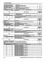
Revision History
Rev. No.
0
Date
2011/2/18
Chapter
2age
Contents
Initial
1-- 1 -
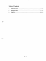
Table of Contents
1.
PREPARATION ..............................:........................................................ 1- 3-
2.
PROCEDURES ........................
3.
CANCEL ................................................................................................... 3-- 15 -
41 . . . . . . . . . . . . . . . . . . . . . . . . . . . . . . . . . . . . . . . . . . . . . . . . . . . . . . . . . . . . . . .
1-- 2 -
2-- 6 -
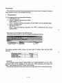
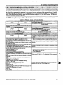
Overview
This instruction document provides operational procedures to change the control
data software version of the Single Wire Saw.
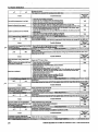
1. Preparation
(1) Tool required for the procedures following:o
1 . USB Memory 1pc
2. Version Upgrade Data
File name: wsd. YMW
( The "YMW" is extension for the version upgrade data.)
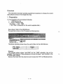
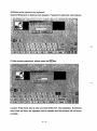
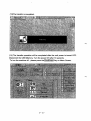
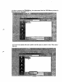
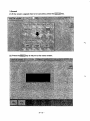
Save above 2 data to the USB Memory.
The saved data is shown on the PC prepared as following picture.
C'.
~
anew !older
A l'ubiish this iolder to the
The above example picture shows the version files into the USB Memory.
IFile
Name
wsd.YMW
Version
****
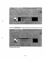
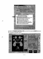
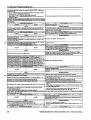
[Caution]
The example picture shows "wsd.YMW" but the "YMW" extension may not be
indicated if the check box "Hide extensions for known file types." was checked on the
PC folder option setting.
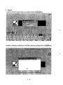
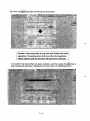
Remove the check from the check box and mouse-click "OK" as following picture.
1- 3-
~
I
Do not mow hidden files and fOldess'
••••• Qio s~'I;i~61'~ au:lJ~~I'·
~ 0 Hi~e extensions fOl known' file iy~s
...
• ·21~F.I'Idl! ~rtft~er~d'.a~~'ihfl·~~fi1es (Recommended)
o launch lcild~r wini:lows in a separate process:
~ Remember each fplder's viewCsetlings
D. Reslore p~evious Icide(' windows allegon
o Show COntrol Panel in My Computer.
~:'S~owencJllpied·or.comPre~~~NrFS ~Ies in color
~. ~~ow pcJ:l"llP, d8scripti lerfcildef a.n~deskl~p items
on
o.Use.
sUTtplefile sharing [I;t ecommendedl.
.
.'
.,
.
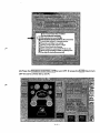
(2) Press the tTENSION CONTROL OFF! to tum OFF ~ press the lS-oNI Key to tum
OFF the servo of the reel Land R.
1- 4-
2: USB Adaptor non-installed(WSD-1A t WSD-2A}
Caution
Be sure to perform after confirming following cautions.
1- 5-
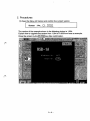
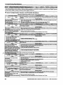
2. Procedures
(1) Open the Menu
I
~
Version and confirm the current version.
MP software :Ver.....JJ•....QQQ
The version of the example shown in the following picture is 2.011.
Explain how to upgrade the version from 2.011 to 2.018 from here as example.
Close the screen by the /CLOSEj key after confirmation.
2-- 6 -
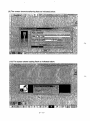
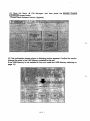
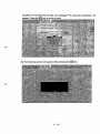
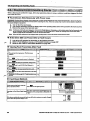
(2) Open the Menu -+ File Manager, and then press the IRestonij screen button.
(MP Software Version Upgrade)
(3) Confirm the version change file exists in the USB Memory installed to the unit. If
the USB Memory is not installed to the unit, install the USB Memory referring on
page 1-5.
<>Please press the IRestore! key. The transfer confirmation screen is shown in
following picture appears
I
I
I
I
Caution: Press each key at only one time firmly from next II
: operation. If pressing more than one time, the operation :
I
I
1 ________________________________________________ 1
I
I will be cleared and the function will not move correctly.
2- 7-
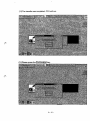
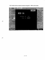
(4)Please press the 10K Ikey. The project password screen is shown in following
picture appears
(5) To enter Project password, please press the Keyboard key
2-- 8 -
0
(6)Please enter password by keyboard.
(Caution)Password is attached with program. Password is attached with program.
(7)After entering password, please press the 10K Ikey.
Caution: Press each key at only one time firmly from next operation. If pressing
more than one time, the operation will be cleared and the function will not move
correctly.
2- 9-
(8)Press th~ Confirmationl key to stop CPU after CPU Control window comes up.
Transferring data will start.
2-- 10 -
(9) The screen shows transferring data as indicated below.
(10) The screen shows loading flash as indicated below.
2- 11 -
(11 )The transfer was completed. CPU will run.
(12)Please press the IConfirmationl key.
2-- 12 -
(13)The transfer is completed.
~
(14) The transfer operation will be completed after the unit power is turned OFF.
Disconnect the USB Memory. Turn the power ON after 10 seconds.
To turn the machine off~ please press the !ShutDownl Key on Menu Screen.
2- 13 -
I
(15) When the screen is activated, open Menu ~ Version to confirm the current
version.
(16) Confirm that the version has been changed to 2.018 on the screen.
(17) This upgrade procedure is now completed.
2- 14 -
3. Cancel
(1 )If you have to cancel vision up, please press the /Cancell key
(2)After confirming contents from Transfer result list, please press the \Clos91 key.
3-- 15 -
(3) Press the /Version/ key to confirm that the control data is not updated.
(4) Confirm that the version is still 2.011.
3-- 16 -
Single Wire Saw
Updated Operating Instruction
(Graphic Data Tranfer Method)
Touch Panel
Takatori Corporation
DOCUMENT
REVISION
Operating Instruction
1
MODEL
WSD Unit
(MP2500)
DATE
2011/2/18
APPROVED
CHECKED
DRAFT
Shimaoka
Revision History
Rev. No. 0
2011/2/18
Date
ChaRter
-,~~ge
Contents
Initial
1- 1 -
Table of Contents
1.
PREPARATION ....................................................................................... 1- 3-
2.
PROCEDURES ....................................................................................... 2-- 6-
3..
CANCEL ..................................................................................... "' .................................................. III. 2-- 13 -
1- 2-
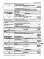
Overview
This instruction document provides operational procedures to change the graphic
data software version of the Single Wire Saw.
1. Preparation
(1) Tool required for the procedures following:
1. USB Memory 1pc
2. Version Upgrade Data (Graphic Data)
Folder Name: ********
(The "*" parts are arbitrary characters. The file folder is for the graphic data.)
3. Version Upgrade Data
File Name: ********
(The "*" parts are arbitrary characters. The "IPP" is extension for the version
upgrade data.)
Save above 2 and 3 data to the USB Memory.
The saved data is shown on the PC prepared as following picture.
72 KB IPP File
The above example picture shows the two kinds of version files into the USB
Memory.
~
I
File/Folder Name
WSDV1008
WSDV1008.1PP
Version
1.008
1.008
[Caution]
The example picture shows 'WSDV1008" and "WSDV1008.1Ppn but the "IPpn
extension may not be indicated if the check box "Hide extensions for known file
types. n was checked on the PC folder option setting.
Remove the check from the check box and mouse-click "OK" as following picture.
1- 3-
o Do not sliow hidden
.
and fOlders
.
."""' ..Q.5boW4b~"epJae$
i(idJg~
.
:,
...
,"
-'
;,
-.:
~ DHide exten~ions for known me ty~S '.
_:
•'!I "AMi ~I'cJtA~rid' O~AMIhb"lIst!m mes (A ecommended)
D Launch folder w.ind.owsin a separate process
'
'Aell}ember e?chf~ldeJ's view settings
Aestorepreviousfolder windows at logon
D.' Show ColltroJ Panel In My Computer ,
~,' Show encrypted'or c:omP.ies.sed, NTFS,fiIes in cokJr
~., Show pop-up descriptK)n for foldeJ and desktop ~ems
~
o
DUSe siinpf8 me sharing ~ecommended)
(2) Press the [ENS ION CONTROL OFF! to turn OFF
OFF the servo of the reel Land R.
1- 4-
-+ press the IS-ONI Key to turn
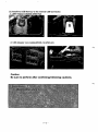
(3) Install the USB Memory to the internal USB Connector.
1: USB Adaptor installed (WSD-K2)
2: USB Adaptor non-installed (WSD-1A)
Caution
Be sure to perform after confirming following cautions.
1- 5-
2. Procedures
(1) Open the Menu
I
Screen
-+ Version and confirm the current version.
:Ver......O,....O.P..O.
The version of the example shown in the following picture is 1.004.
Explain how to upgrade the version from 1.004 to 1.008 from here as example.
Close the screen by the !CLOSE! key after confirmation.
2- 6-
(2) Open the Menu ~ File Manager, and then press the IMonitor Systeml
IUPGRADE! screen button.
(Touch Panel Software Version Upgrade)
(3) The confirmation screen shown in following picture appears. Confirm the version
change file exists in the USB Memory Instal/ed to the unit.
If the USB Memory is not installed to the unit, install the USB Memory referring on
page 1-5.
2- 7-
(4) When pressing the !Change! key, the data saved into the USB Memory shown in
followi
pears.
(5) Touch the desired file and confirm the file name is shown in the "File name:"
text box.
(6) Press the IOpenl key after confirming the desired file.
rC~~~i~~~ -Pr~~~-;;c-h" k~; ~~ ~~i; ~~-e-ti~~-fl;~I; ir~; ~~~~ 1
: operation. If pressing more than one time, the operation
I
I
:_~~L~!~1!~~~_~~~~~!1~~~~~~_~~L~~~~_~~~~~~~:!ly~ __ !
(7) Confirm the desired file has been selected, and then press the IQBl key to
start copying the data after changing the screen shown in following picture.
2- 9-
(8) When the transferring the data, the message "The copy was completed." will
(9) The following screen will appear after pressing the [QBI key.
2-- 10 -
(10) Return to Menu screen and turn off power once.
Turn off the breaker after Touch panel screen disappears.
(11) The transfer operation will be completed after the unit power is turned OFF.
Disconnect the USB Memory.
Tum the power ON after 10 seconds.
When the screen is activated, open Menu
version.
2- 11 -
-+
Version to confirm the current
(12) Confirm that the version has been changed to 1.008 on the screen.
2- 12-
3.Cancel
(1) If the version upgrade has to be canceled, press the ICanceij key.
(2) Press the lMenij key to return to the menu screen.
2- 13-
(3) Press the !Versionl key to confirm that the graphic data is not updated.
(4) Confirm that the version is 1.004.
This completes the cancel operation.
2- 14-
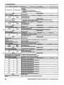
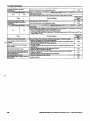
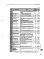
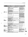
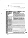
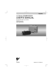
6.3 Drive Alarms, Faults, and Errors
• Types of Alarms, Faults, and Errors
Check the LED operator for infonnation about possible faults if the drive or motor fails to operate. Refer to Using tTle
Digital LED Operator on page 70.
If problems occur that are not covered in this manual, contact the nearest Yaskawa representative with the following
infonnation:
• Drive model
• Software version
• Date of purchase
• Description of the problem
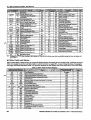
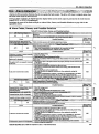
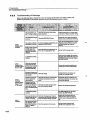
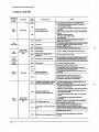
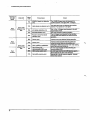
Table 6.4 contains descriptions of the various types of alarms, faults, and errors that may occur while operating the drive.
Contact Yaskawa in the event of drive failure.
Table 6.4 Types of Alarms, Faults, and Errors
==,=H=:rn
~.~~~~~!i!!~~~!m~~~~~~~~~~~~~~~
drive detects a filult:
digital operator displays text that indicates the specific fault and the ALM indicator LED remains lit until the
is reset
• The fault interrupts drive output and the motor coasts to a stop.
• Depending on the setting, the drive and motor may stop via different methods than listed.
• Ira digital output is programmed for fault output (H2-DD =E). it will close ira fault occurs.
the drive detects a filult. it will remain inoperable until that filult has beea reset Refer to Fault Reset Methods on
settings confliet
one anothcrordo not match
settings
error.
detects an operation error:
operator displays text that indicates the specific error.
Multi-tuncbon contact outputs do not operate.
an operation error, it will not operate the motor until the error has been reset. Correct the settings
• Alarm and Error Displays
• Faults
i
When the drive detects a fault, the ALM indicator LEDs remain lit without flashing. If the LEDs flash, the drive has
detected a minor fault or alarm. Refer to Minor Faults and Alarms on page 230 for more infonnation. Conditions such 0
as overvoltage or external faults can trip both faults and minor faults, therefore it is important to note whether the LEDs ~
remain lit or if the LEOs flash.
~::s
!
YASKAWA ELECTRIC SIEP C710606 16A YASKAWA AC Drive - V1000 Technical Manual
229
[Excerpted] YASKAWA AC Drive V1000
Technical Manual
I
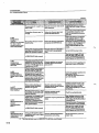
6.3 Drive Alarms, Faults, and Errors
• Types of Alarms, Faults, and Errors
Check the LED operator for information about possible faults if the drive or motor fails to operate. Refer to Using tlte
Digital LED Operator on page 70.
If problems occur that are not covered in this manual, contact the nearest Yaskawa representative with the following
infonnation:
• Drive model
• Software version
• Date of purchase
• Description of the problem
Table 6.4 contains descriptions of the various types of alarms, faults, and errors that may occur while operating the drive.
Contact Yaskawa in the event of drive failure.
of Alarms. Faults, and Errors
~~
, .... '".'.,:,
.. ;:"
the drive detects a fault
• The digital operator displays text that indicates the specific fault and the ALM indicator LED remains lit until the
isrcscl
• The fault intcnupts drive output and the motor coasts to a stop.
• Depending on the setting, the drive and motor may stop_via different methods than listed.
• If a digital output is programmed for fault output (H2-CD =E), it will close if a fault oc:c:urs.
the drive detects a fault, it will remain inoperable until that fault has been resel ReIer to Faull Reset Methods on
operatic)n error.
drive detects an operation error:
• The digital operator displays text that indicates the specific error.
• Multi-function contact outputs do not operate.
the drive detects an operation error, it will not opc:ratc the motor until the error bas been reset. Correct the settings
CD'OI' to resel
the
~_ ~-v-- , __- occ:ur while perfonning Auto-Tuning.
drive detects a tuning error:
• The digital operator displays text indicating the specific error.
• Multi-function contact outputs do not operate.
• Motor coasts to stop.
• Remove the cause of the error and
• Alarm and Error Displays
• Faults
When the drive detects a fault, the ALM indicator LEOs remain lit without flashing. If the LEOs flash, the drive has
f
detected a minor fault or alann. Refer to Minor Faults and Alorms on page 230 for more information. Conditions such ~
.:
as overvoltage or external faults can trip both faults and minor faults, therefore it is important to note whether the LEOs !
remain lit or if the LEOs flash.
'S
~
YASKAWA B.ECTRIC SIEP C710606 16A YASKAWA AC Drive - V1000 Technical Manual
229
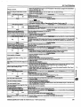
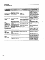
6.3 Drive Alarms, Faults, and Errors
when occurring at drive power up. When one of the faults OCCUIS after successfWly starting the drive. the display will
• Minor Faults and Alarms
When a minor fault or alarm occurs, the ALM LED flashes and the text display shows an alarm code. A fault has occurred
if the text remains lit and does not flash. Refer to Alarm Detection on page 243. An overvoltage situation, for example,
can trigger both faults and minor faults. It is therefore important to note whether the LEOs remain lit or if the LEOs flash.
230
YASKAWA ELECTRIC SIEP C710606 16A YASKAWA AC Drive - V1000 Technical Manual
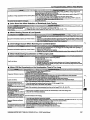
6.3 Drive Alarms, Faults, and Errors
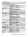
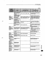
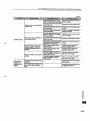
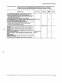
• Operation Errors
Table 6.7 Operation Error Displays
",',
oPEG':
oPE02
oPE03
oPE04
oPEOS
oPE07
Drive Unit Setting Erro""r==~'4'=~
Parameter Setting Range Error
249
Multi·Function Input Setting Error
249
Terminal Board Mismatch Error
250
150
Run Command Selection Error
Multi-Function Analog Input
250
Selection Error
r"B~I1~rjtolt;gp
L;) ;iK'DfjDr~2!'
oPE G8
0
G9
oPE :0
oPEOS
oPE09
oPEIO
oPEl I
oPE 13
,Parameter Selection Error
PID Control Selection Error
VlfData Setting Error
Carrier Fr uency Set1ing Error
Pulse Train Monitor Selection Error
250
251
251
251
• Auto-Tuning Errors
YASKAWA aECTRIC SIEP C71060616A YASKAWA AC Drive - V1000 Technical Manual
231
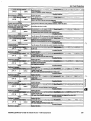
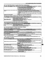
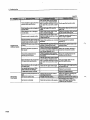
6.4 Fault Detection
• Fault Displays, Causes, and Possible Solutions
232
YASKAWA ELECTRIC SIEP C710606 16A YASKAWA AC Drive - V1000 Technical Manual
6.4 Fault Detection
YASKAWA ELECTRIC SIEP C71060616A VASKAWA AC Drive - V1000 Technical Manual
233
6.4 Fault Detection
[PF2Gor[PF2 t
CPF20orCPF21
CPF22
EF
J
EF2
EFl
EF3
EFJ
EF'I
EF4
EFS
EFS
EF6
EF6
EF?
EF7
IRemo've the cause of the external fault and reset the fault.
234
YASKAWA ELECTRIC SIEP C71060616A YASKAWA AC Drive - V1000 Technical Manual
6.4 Fault Detection
____ have been CODJlected properly to
,_~_.~=-,,-
tenniDals
for
20 to 2F).
line.
in this manual to fasteD the termiDaIs. Refer to WIre Size
YASKAWA ELEClRlC SIEP C71060616A YASKAWA AC Drive - V1000 Technical Manual
235
6.4 Fault Detection
Refe,. to Wire Site and
Ensure all values are the same.
of the motor cables bas shorted out or
is a grounding problem.
,~,
\
is not operating as expected.
IExce5Jdve torque compensation.
oFR03
oFROli
oFA04
oFR30tooFRI.f3
oFAJO to oFA43
236
YASKAWA ELECTRIC SIEP C71C60616A YASKAWAAC Drive- V1COO Technical Manual
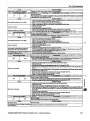
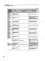
6.4 Fault Detection
Cause
Option card or hardware is damaged.
Possible Solution
Replace the o~tion card. Contact Yaskawa for consultation.
;' ~t}',~, '?:,LED:~Ope[a.oI'D.iSplay:.:,·r'7:::f'.!t;\: ~f"~'l:'i}'j~;;:,' '.,:E<~~,f~~4'i('~' <'t~(Fiiil)tNam~~:t~Xf'A~:>80w';s-i~p:,s?:,1,1~;it~~: !.:: ,';;~t(*;ft~
Heatsink Overheat
aH
oH
The t~ of the heatsink ex~ed the value set to LS"()2 (9O-100D C). Default value for LS-02
is detennined DY drive capacity (02-04J.
Cause
Surrounding temperature is too high.
Load is too heavy.
__ AI
I' t l '
ped.
In",""" coo mg an 15 stop
•
•
•
•
•
•
•
•
•
Possible Solution
Check the temperature surrounding the drive. Verify temperature is within drive specifications.
Improve the air circulation within the enclosure panel.
[nstall a fan or air conditioner to cool the surrounding area.
Remove anything near the drive that might be producing excessive beat.
Measure the output cuncnl
Decrease the load....
. "CL n2".
Lower the carrier
' \' v-v 'J.
Replace the cooling fan. Refer to CooUng Filn Replace",ent on page 269.
After replacing the drive, reset the cooling fan maintenance parameter (0+03 = "0").
:j)_;i:'t:::tEI(()p:a:jltimDiSiiJiii: ".,:KtX;.iJ} '!i2J,;f£: lK:j:';~"'0Jl@;"'0IS:.1K:::?J:t,;$JiJl:Zi2IT?FlUilfName":·0;\jt~i':~i' :v$4-"'~;~;;"):\~i J\,J!,\:: ',.: ,'<,
<S{~::' ;
Overheat I (Heatsink Overheat)
aH:
oHI
The temperature of the heatsink has exceeded the overheat detection level.
Possible Solution
Cause
• Check the temperature surrounding the drive.
• Improve the air circulation within the enclosure panel
Swrounding temperature is too high.
• [nstaU a fan or air conditioner to cool the swrounding area.
• Remove anything near the drive that might be producing excessive beal
• Measure the output currenl
Load is too heavy.
• Lower the carrier ftequency (C6-02).
• Reduce the load
• Check the maintenance time for the cooling fan (U4-04).
The internal cooling fan has reached its
erformance life or has maJfimcti ed
• If U4-04 exceeds 90%, Jeplace the cooling fan. Refer tD Cooling Ftm Replacement on page 269.
P
on
• After replacing fan. reset the fan maintenance time (04-03 = "0';.
Current Oowingto control circuit terminaJ +V • Check the current level of the terminal.
exceeded the tolerance leveL
• Set the current to the control circuit termiDa.I to be 20 mA or less.
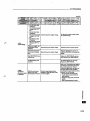
C1f~~J¥~~~mmt~iJJfSiJaF'-~;;.:sXk~:;! L1EZ~*"Tl\1?~fH·':0{;y=~~~!~I/}~~tI:\~\'·~rsYFj(D1£r~·:T1:£:?X~~~:~J7f;·;i!'t~:~-:~·~:·:~~.~r~~§J~
Motor Overheat Alarm (PTe Input)
aH3
oH3
• The motor overheat silDUll to analog input terminal Al or A2 exceeded the alarm detection level
• Detcc1ion requires multi-function analog input H3-02 or m-IO be set to "E".
Cause
•
•
•
•
Motor has overheated
•
•
•
•
•
Pomble Solution
Check the size of the load, the acceVdeccl times and the cycle times.
Decrease the load
Increase the acceleration and deceleration times (Cl"()l through CI-08).
Adjust the preset Vlfpattem (EI-04 through EI-IO). This wiD mainly involve reducing El"()8 and
El-IO.
Be careful not to lower El"()S and EI-IO excessively. as this reduces load tolerance at low speeds.
Check the motor-rated cuncnl
Enter the motor-rated current as indicated on the motor nameplate (E2..()l).
Ensure the motor cooling system is operating nonnally.
Repair or replace the motor cooling system.
j)J~>iFi. :mID!()perafii~J8Y}~'i12n]' '~~~~)Xt0':10Jf::li1~~:gIKmnl~ii'l1.ts;.!1ijiJ.~~~&:illiJl:J;~5tjj'':~::'·~1;;;
Motor Overheat Fault (PTC Input)
oH'I
o H 4 . The motor overheat signal to analog input terminal A1 or A2 excc:cdcd the fault detection level.
• Detection requires that multi-function 8nalog input H3-02 or ~ I 0 '" "F'.
Cause
Possible Solution
Check the size of the load. the acccVdeccl times and the cycle times.
Decrease the load
Increase the acceleration and deceleratioD times (Cl"()l through CI"()S).
Adjust the preset V/fpattern (EI-04 through EIAIO). This will mainJy involve reducing EI-OS and
EIAIO. Be careful not to lower El"()8 and EIAIO excessive1ybecausc this reduces load tolerance at
~l~ow~'~~~______~________________________________________~
•
•
•
•
Motor has overheated.
•
•
•
•
Check the motor-rated currenl
Enter the motor-rated current as indicated on the motor nameplate (E2-01).
Ensure the motor cooling system is operating nonnally.
Repair or replace the motor cooling sYstem.
\·.:;·~)·':,LEDlOpeiittirJD.ijpliYL~fd;··~~:);~·~;: ·~~~~~~,~\~~?F.$Et£'iu~~~·<~·;f':Zi7V{~Di:ilt-.1f~~~?~@J~ifJi~~C'~·:"·~~\\~t~;~~f';·;.:<;~·::'·\;.J.i;!.~
Motor Overload
The electrothermal sensor tripped overload protection.
Cause
Possible Solation
Load is too heavy~
Reduce the load
Cycle times ~ too short during acceleration Increase the acceleration and deceleration times (CI"()I through CI-OS)
and deceleration.
•
aL I
oLI
YASKAWA ELECTRIC SIEP C710606 16A YASKAWA AC Drive - V1000 Technical Manual
237
1.11
~
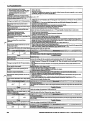
6.4 Fault Detection
• Drive
at low
• Overload may occur at low speeds when
using a generai-pwpose motor, even if
operating within the rated current
limitation.
• Reduce the load.
• Increase the speed.
• If the drive is supposed to operate at low speeds, either increase the motor capacity or use a motor
specifically designed to operate with the drive.
BI-IO). Parameters RI-08 and RI-IO may need to
E2-01.
IMtotol~ ov'cchcatc:d by overcxcitation
Search related parameters are not set
proper values.
the settings for the acccleratioD and deceleration times (CI-Ol through CI-08).
preset Vlfpattem (EI-04 through BI-IO). This will mainly
reducing EI-08 and
not to lower EI-08 and EI-I0 excessively because this reduces load tolerance at low
the settings of parameters L6.02 and 16-03.
the status of tile load. Remove the cause of tile fault.
the settings of parameters 16-05 and [.6..06.
ot5
238
oL5
YASKAWA ELECTRIC SIEP C71060616A YASKAWAAC Orive- V1000 Technical Manual
6.4 Fault Detection
oP"
oPr
• The external operator has been disconnected from the drive.
Note: An oPr fault will occur when aU of the following conditions are true:
• Output is interrupted when the operator is disconnected (02-06 = 1).
• The nm command is assigned to the operator
-02 = 0 and LOCAL has been
operator is not properly connected
drive.
05
ou
ov
IDe:ceII!!!'3.1ion time is too short and
/reg:eoerati've energy flows from the motor
the drive.
accclcmtion time causes the motor to
IOVl:rs!lIOOt the speed reference.
IExc:cssrve braking load.
Ilmllrop'Cf Setting of Speed Search related
lPar.ilJDe'tcrs. (Includes Speed Search after a
Imclme:ntaJ':'j power loss and after a fault
YASKAWA B.ECTRIC SIEP C71060616A YASKAWA AC Drive - V1000 Technical Manual
239
6.4 Fault Detection
inertia has been set incorrectly.
PF
PF
• Check the load inertia settings when using KEB, overvoltage suppression or Stall Prevention
deceleration.
Ll-2S
in accordance with the load.
phases. Detected
is loose wiring in the drive input
lterm:inals.
is excessive fluctuation in the drive
power voltage.
• Check the voltage from the drive input power.
• Review the possible solutions for stabilizing the drive input power.
• Disable Input Phase Loss Detection (1.8-05 ="0''). PF is detected if DC bus ripple is too high. If it
is disabled, there is no fault but the ripple is still too high, thereby the capacitors arc stressed more
and lose lifetime.
main circuit capacitors are worn.
.H
IDccc:ll:nItion time is too short and excessive
lrel!=I:nItive energy is flowing back into the
and Resetting
240
YASKAWA ELECTRIC SIEP C71060616A YASKAWAAC Drive- V1000 Technical Manual
6.4 Fault Detection
the minimum value set for torque detection (L6-02) for longer than the
value set for torque detection (L6-0S) for longer than the
" ,
uu'
YASKAWA ELECTRIC SIEP C71060616A YASKAWA AC Drive - V1000 Technical Manual
241
6.4 Fault Detection
Internal circuitry is damaged.
• Cycle power to the drive. Check if the fault reoccurs.
• Replace the drive if the Cault continues to occur.
Undervoltage 3 (Inrush Prevention Circuit Fault)
The inrush prevention circuit has failed.
Cause
Possible Solution
• Cycle power to the drive. Chcck if the fault reoccurs.
Thecontactorontheinrushpreventioncircuit • Replace the drive if the fault continues to occur.
is damaged.
• Check monitor U4-06 for the perfonnance life of the inrush prevention circuit.
• RepJace the drive ifU4-06 exceeds 90%.
Uu3
242
I
Uv3
YASKAWA ELECTRIC SIEP C71060616A YASKAWAAC Drive-V1000 Technical Manual
6.5 Alarm Detection
Alanns are drive protection functions that do not operate the fault contact The drive will return to original status when
the cause of the alann has been removed.
During an alann condition, the Digital Operator display flashes and an alann output is generated at the multi-function
outputs (H2-01 to H2-03), if programmed.
Investigate the cause of the aJann and Refer to Alarm Codes, Causes, and Possible Solutions on page 243 for the
appropriate action.
• Alarm Codes, Causes, and Possible Solutions
Table 6.10 Alarm Codes, Causes. and Possible Solutions
bb
bb
Baseblock
Drive output interrupted as indicated by an external baseblock signal.
Caase
Minor Fault
Possible Solations
(H2-[J[J = 10)
External baseblock signa) entered via
multi-functioo input terminal (SI to S7). Check external sequence and baseblock signal input timing.
bUS
bUS
No output
Option Communication Error
After initial communication was established, the connection was lost.
o Assign a run command frequency reference to the option card.
0
Cause
Minor Fault
(HZ-CD"" 10)
Possible SolatioDs
Connection is broken or master controller Check for fau!tr wiring.
. .
• Correct the wmng.
stopped comm\DllcatiDg.
• Repair ground wiring or disconnected cables.
If
there arc no problems with the wiring and the fault continues to occur, replace the
Optioncardi5dwmag~
0
~tioncard.
tion card is n t ...-Iy connected • The conn.ector pins on the option card arc not properly lined up with the connector pins
0 pro~..
on the drive.
e op .
to the drive.
Reinstall the option card.
• Check options available to minimize the effects of noise.
o Take steps to counteract noise in the control circuit wiring. main circuit lines and
ground wiring.
• Try to reduce noise on the controller side.
o Usc surge absorbers on magnetic contactors or other equipment causing the
A data error occurred due to noise.
disturbance.
• Use cables recommended by Yaskawa, or another type of shielded line. The shield
should be grounded on the controller side or on the drive input power side.
• All wiring for communications devices should be separated from drive input power
lines. Ins1all an EMC noise filter to the input side of the drive input power.
TIl
YES
YES
YES
0
YES
1:·;l;L:>:<~JiED1Qi~~fci'~»JlP1iYF¥£t~: r.'jZ~;z2~ ~·~:>·:;'(i}L~/;7::·!£~<~~~.D~F~t~~?;}&:i£i~ll·ra1dt~NiiD~-\i~~{':~ .~.:;,).J. ~:'~~t~~·~;~~':-:~£~~~·.~-:.· ~-- ?J~:~~,EE~~
[RLL
CALL
Cause
Serial Communication Transmissioo Error
Communication has not yet been estabtish~
Communications wiring is faulty, there is o Check for wiring errors.
o Correct the wiring.
a short circuit, or something is not
• Remove and ground shorts and reconnect loose wires.
connected properly.
Check communications at start-up and correct pro
Pro
error on the master side.
o Perfonn a self-diagnostics check.
Communicatioos circuitry is damag~
• Replace the drive if the fault continues to occurs.
[E
CE
Cause
Minor Fault
(HZ.DC '" 10)
Possible Solutions
YES
errors.
YES
YES
Control data was not received correctly for two seconds.
Possible Solutions
• Check options available to minimize the effects ofnoisc.
• Counteract noise in the control circuit wiring, main circuit lines and ground wiring.
o Reduce noise 00 the controller side.
o Use surge absorbers on magnetic coatactors or other equipment causing the
disturbance.
A data error occurred due to noise.
o Use cables recommended by Yaskawa or another type of shielded line. The shield
should be grounded on the controller side or on the drive input power side.
o Separate all wiring for communications devices from drive input power lines. Install
an EMC noise filter to the input side of the drive input power.
•
the HS parameter settings as well as the protocol setting in the controller.
Communication protocol is incompatible. • Check
Ensure settingS arc compatible.
YASKAWA ELECTRIC SIEP C71060616A YASKAWAAC Drive - V1000 Technical Manual
Minor Fault
!CH2-[J[J '" 10)
YES
YES
243
~
6.5 Alarm Detection
YES
YES
YES
Possible SolutioDs
Possible SolutioDs
EF
EF
Cause
YES
EFt
244
EF2
EF2
EF3
EF3
EF'I
EF4
EFS
EFS
EF6
EF6
EF'1
EF7
YASKAWA ELECTRIC SIEP C71060616A YASKAWAAC Drive- V1000 Technical Manual
6.5 Alarm Detection
Cause
MInor FauU
Output
(Hl·OO." 10)
Possible SoludoD'
An external device has tripped an alann
function.
Remove the cause of the cxternal fault and reset the multi-function input value.
YES
• Ensure the signal lines have been connected properly to the tenninals assigned for
cxternal fault detection (HI.[JO'" 20 to 2F).
YES
• Reconnect the signa\line.
Multi-function contact inputs are set
• Check if the unused terminals bave beeD set for HI-OO 20 to 2F (Extcmal Fault).
YES
inconecUy.
• Change the tennina1 settings.
i.~._ ·'2D.i,U:D:Oier,atoI';DISJ»layt ,t,,;;~i!' <t!t-!~,~-;;J'!!Ai§~~ ·:.:;;j1J'(4/,' ;i\\'. ,y ..... MiD'o".FawiName~::Xi'~i:, .' :'t.:~1tf;,:·~i'4f~;·;;.,:.~~;",;.:,:,{{;:~;::;"'t:
Excessive pm Feedback
FbH
FbH
The pm feedback input is higher than the level set in bS-36 for longer than the time set in bS-37. and
bS-12 is set to I or 4.
Minor Fault
Output
Possible Solatlons
Cause
(H2.QO"10\
Wiring is incorrect.
=
?arameters settings for bS-36 and bS-37 are Check parameters bS-36 and bS-37.
YES
mconect.
pm feedback wiring is faulty.
Comct the wiring.
YES
Feedback sensor bas malfunctioned.
Check the sensor and replace it if damaged
YES
Feedback input circuit is damaged.
Replace the drive.
YES
.. ·,\lffiL'EDLoperatiiifUii!taI2~~ 1;';'1::/'" ."':':I(1;'<S;;. ,'·::-'f;,:-<L~;:'2;2. '-l\flDor~F.aialfNmL_3>5·..J:}i:::.'ij/;i:\;:t~~,~~~~,,,3.t'
pm Feedback Loss
FbL
FbL
The PlD feedback input is lower than the level set in bS-13 for longer than the time set in bS-14, and
bS-12 is set to I or 4.
Minor Fault
Output
Cause
Possible Soladons
(H2.QO::::l 10)
?arameterssettiagsforbS-13 and bS-14 are Check parameters bS-13 and bS-14.
mconect.
PID feedback wirin2 is faulty.
Correct the wiring.
Feedback sensor bas malfimctioned.
Check the sensor and replace it if damaged
Feedback iDput circuit is damaged.
Replace the drive.
YES
YES
YES
YES
;:":~()'era~'"'f::l)iiji_liit~~ ~':;:~L,'lL""i;,:;~C:;:;h£;;~d,·it&~..MIiiOrJ..F.auJf!~_i.•:.ll-lf/l~:~~~~:jVtf~i~~·?iBii·
Hbb
Hbb
Safe Disable Signal Input
Both Safe Disable Input channels are open.
MiuorFault
Output
1(H2·oC oa IO}
There is 110 signal at tenninal HI
Check ifexternal safety circuittripped and disabled the drive.lfthe Safe Disable fUnction
YES
.
is Dot utilized, check if the tenninals HC HI and H2 are linked.
~Y' both Safe Disable channels are Replace the drive.
YES
Cause
HbbF
Possible Solutionl
HbbF
Safe Disable Siguallnput
One of the Safe Disable iJrput channels is open.
Cause
H[R
Possible Solutions
HCA
=
Current Alarm
IDrive current exceeded OVercurreDt warning level (1S0% oCthe rated cwrent).
Cause
Load is too heavy.
MInor FaalC
Output
(II2-CC 10)
Possible Solution.
• Measure the current flowing through the motor.
•
•
Ac:ccleration and deceleration times are too •
short.
•
•
A sp~aI:purpose ~otor is being used, or •
the drive IS attemp~
to run a motor
•
gn:ater than the max nnurn allowable
capacity.
Reduce the load or increase the capacity of the drive.
Calculate the torque rc:qujred during ac:cclcnltion and for the inertia moment
If the torque level is not right for the load. take the foUowing steps:
Increase the acceleration and deceleration times (CI-OI through CI-(8).
increaSe the capacity of the drive.
Check the motor capacity.
Use a motor appropriate forthe drive Ensure the motor is within the allowable capacity
_ftge
.
..... .
.
. nTh'
eed tak·
the al
The c:urreIlt level increased due to Speed
Search after a momentary power loss or The alann ~ I!Ppear o.nlY bne y. ere IS no n
to e action to prevent
arm
while attempting to perform. a fault restart. from oc:cumng m such instances.
YASKAWA aECTRIC StEP C71060616A YASI<AWAAC Drive - V1000 Technical Manual
MInor FaaU
Output
(H2.QO ... 10)
YES
YES
YES
YES
245
6.5 Alarm Detection
05
oS
Overspeed (for Simple V/fwith PG)
Pulse input (RP) indicates that motor speed feedback exceeded Fl-OB setting.
Overshoot or undershoot is occwrlng.
PG pulse settings are incorrec:t.
..
. to
Parameter settings are mappropna.
• Adjust the gain by using the pulse train input parameters (H6-02 through H6-05).
• Adjust the speed feedback accuracy.
• Increase the settiDgS for CS-O I (Speed Control Proportional Gain I) and reduce CS-02
(Speed Control ID~ Time I)~
SettheH6-02(PulscTrainlnputScaling)-lOO%,thenumbcrofpulsesduringmaximum
motor revolutions.
Check the setting for the overspeed detection level and the overspeed detection time
(FI-OB and FI-09).
L-:;.' ," ,- ',' LED;,dperatoj\:l)liPJiYE.:\.:'~c'~·n ~Y'l!F,J0;',F~i': ";, "
ov
Ou
Minor Faull
Output
1(lt2-CO = 10)
Possible Solutions
Cause
YES
YES
YES
:{"/;~ -:;~:I!',::'.J\):(\MlDOi\:F81iJtNamec ~,:,;;;::::J;;;;:'~" _' .,--;:,7Ji:-i'f.i;::~'·":;'\~.~'t't;;"
DC Bus Overvoltage
The DC bus voltage exceeded the trip point
For 200 V class: approximately 410 V
For 400 V class: approximately 820 V (740 V when HI-01 < 400)
Possible Soilition.
MlnorFault
Output
(H2-00 =10)
Surge voltage present in the drive input
power.
• Install a DC reactor or an AC reactor.
• Voltage surge can result from a thyristor convertor and a phase advancing capacitor
operating on 1he same drive input power system.
YES
• The motor is short-circuited.
• Ground cwrent has over-charged the
main circuit capacitors via the drive
input power.
• Check the motorpowercablc, relay terminals and motorteJminaJ box for short circuits.
• Correct grounding shorts and tum the power back on.
YES
Noise interference causes the drive to
operate inconcetly.
• Review possible solutions for handling noise interference.
• Review SectiOD on handliDg noise interfcn:ncc and check control circuit lines, main
circuit lines and ground wiring.
• If the magnetic contactor is identified as a source of noise, install a surge protector to
theMC coil.
Set number of fault restarts (LS-O 1) to a value other than O.
Cause
YES
YES
t::ii!1'T\':IJm1OPeJlaiO~..nliiiliiYl!~b'C' ~;i:.'~i2:;r.-~;"~'S":":""'T(;,!0":;;'iJf,mJR'i;'«'~iiif3a"'illtiNimieIB~T.iiL,i2YiQ}&,;;,0':it:f;,§f}-
PR55
PASS
MEMOBUSlModbus Comm. Test Mode Complete
MEMOBUSlModbus test has finished
normally.
PGo
Minor Fault
Output
(Hl-DC '" 10)
Possible Solatlons
Cause
PGo
This verifies that the test was successfUL
No output
PO Disconnect (for Simple VIf with PO)
Detected whcnno PO pulses received for a time longer than setting in Fl-14.
CIUse
MIIlorFaalt
Output
(Hl-IJO colO)
YES
YES
YES
Possible Solutioal
Pulse input (RP) is disconnected.
Pulse input (RPl wiring is wrong.
Motor brake is cogaged.
Reconnect the pulse input (RP).
Concet the wiring.
Ensure the brake releases properly
L;m-~'("jreml1iiji(o~DiiPJilm;',:<;f:i: ~J~~~~:::~"-S~:MiIloi!F"1i1t;Nami,:,; jf!i~J§'LtC2::;.~~~1;;%,~_~ ,_},~ 'fJ~",,,
rUn
rUn
CIlise
A motor switch command was entered
during run.
Motor Switch during Run
A command to switch motors was entered during run.
Possible Solutioa.
MIIlor Fault
Output
1(Hl-OO =10)
Change the operation pattern so that the motor switch command is entered while the drive
is stopped.
YES
::i::~ll!EJ(OperilorDJ5PIilL -,;,,~:;; ~';iF,;,g;",;lj;:F,:~:J',;,:':1'il!£1C:~L"~"l",-~oi\Fi"l](Name'
5f
SE
Cause
~;'J.-d'?-.~; 1~ ..:;;'::::3:""';'
Possible Solutions
A digital input JUOgrammed to 67H
(MEMOBUSlModbus test) was closed
while the drive was nmning.
uu
'
Ul3
Calise
Inappropriate parameter settings.
. '.
::~·~2.i
MEMOBUSJModbus Communication Test Mode Error
Stop the drive and nm the test again.
MlnorFault
Output
(Bl-CO = 10)
No output
Undertorque Detection I
Drive output current (or torque in OLV) less than 1.6-02 for longer than L6-0J time.
Possible Solatlons
Check parameters 1.6-02 and L6-03.
YASKAWA ELECTRIC SIEP C710606 1M YASKAWA AC Drive - V1000 Technical Manual
MlnorFault
Output
(Hl-DO c 10)
YES
247
~
f
i
'S
~
6.5 Alarm Detection
Load has dropped or decreased
significantly.
Check for broken parts in !he transmission system.
YES
:?;,~~~lnED: Oplrafii'i:D,iSplaY:":¥f"~j~i.i~ ~sw..~i?~:::~~·;~;'~·i!;~~~<~~~{i:·:"~~::~~~·,,~J:&l.ttiIt.f~~~.·:~;MiDoi-Fault:Nam~1i~f1~\~~~~·~~~·;~\~~:\~.f3;%:i£,::?;:!tij;~~~~~f.:
ilL II
utA
Cause
Undertorque Detection 2
Drive output c:um:nt (or torque in OLV) less than L6-0S for longer than 1.6-06 time.
Possible Solutions
Inappropriate parameter settings.
The load bas dropped or decreased
significantly.
Check parameters L6·0S and L6·06.
Check for broken parts in the transmission system.
Minor Fault
Output
1(B2oee =10
YES
YES
i-,{;~t]:k~l;LEltOjieiiitOiJjlSPljiy.~:ti\JF'~ r::;;:::-;':::.;~:::./~i~,,;'';~:;'iiit;(;)1i~)t!$~~¥r,.<:Mli{'iF'iiilt:~ame~~}~~'t1f,';'~:~~}~~~·'i::~~~i
"
Uv
uu
Cause
Phase loss in the drive input power.
Loose wiring in the drive input power
tenDinals.
Undervoltage
One of the following conditions was true when the drive was stopped and a run command was entered:
• DC bus voltage dropped below the level specified in U·OS.
• Contactor to suppress inrush current in the drive was open.
• Low voltage in the control drive input power. This alann outputs only ifU-Ol is not 0 aDd DC bus
voltage is under L2·0S.
Minor Fault
Output
Possible Solulions
[(Hloee =10)
Check for wiring errors in the main circuit drive input power. Correct the wiring.
YES
• Ensure the terminals have been properly tightened.
YES
• ~ply the tightening torque specified in this manual to fasten !he terminals. Refer to
,re Gauges and Tightening Torque on page 51
• Check the voltage.
There is a problem with the drive input
• Lower the voltage of the drive input power so that it is within the limits listed in the
power voltage.
specifications.
•
Cbeck the maintenance time for the capacitors (U4-0S).
Drive internal circuitry is wom
• Replace the drive ifU4-0S exceeds 90%.
The drive input power transformer is not • Check for a tripped alann when the magnetic contactor.line breaker and leakage
large enough
voltage drops when the
breaker are turned on.
power is switched on.
• Check the capacity of !he drive input power transformer.
Air inside the drive is too hol
• Check the temperature inside the drive.
The CHARGB indicator light is broken or
• Replace the drive.
disconnected.
ana
248
YES
YES
YES
YES
YES
YASKAWA ElECTRIC SIEP C71060616A YASKAWAAC Drive - V1000 Technical Manual
6.6 Operator Programming Errors
(~TI:~jl,\tQBI~__frjb.Itlim9T·~,g:;t\'······
An Operator Programming Error (oPE) occurs when an inappropriate parameter is set or an individual parameter setting
is inappropriate.
The drive will not operate until the parameter is set correctly; however, no alann or fault outputs will occur. If an oPE
occurs, investigate the cause and Refer to oPE Codes, Causes, and Possible Solutions on page 149 for the appropriate
action. When an oPE error is displayed, press the ENTER button to display U 1-18 (oPE fault constant). This monitor
displays the parameter causing the oPE error.
• oPE Codes, Causes. and Possible Solutions
Table 8.11 oPE Codes, Causes, and Possible Solutions
:~t'i:&)"?!'i;!; ··<·~!f£'ED.;oPintOjtDrSplaYZ;~k;~J;;j~'~~'·:(iii$".,m:; :;-S1]:l;!Xtif.'j:~~~~:;];;~~e.En:oriNamer:j:],:;f.1j;,gl:<·'h~!.~~.~~-,:.f~0c~I·!'
Drive Capacity Setting Fault
Drive c:apacjty and the value set to 02-04 do not match.
Cause
Possible Soludons
The drive capacity setting (02-04) and the actual capacity of the drive are Correct the value set to 2-04
not the same.
0
•
oPEG:
oPEOI
'~0J~iJ:Jl!X«('%',l!JID3:~~~iSplaYXtB7{;;'£/!tzrf;;~~iZLt1lf r:1:d,j:;~~:2;.U:i:L~fial1N.aiie~~LL~lti'!it&Z~~1F·~,,:.
oPEG2
0PE02
~aramcter Range Sctting Enor
Use UI-18 to find parameters set outside the range.
Cause
Possible Solutions
Parameters were set outside the possible setting range.
Set parameters to the proper values.
Note: Other errors arc given prcccdcnce over oPE02 when multiple errors occur at the same time.
~"!'~.Z.~~tEJfJ)jiiiflOi1DJlpm~fllJ:~ELd?~~- ~1TI?6t2(~~~E60li.Ramii.f',~1!';:t~:i.·:'~~Y~L~i!i~~~~·· ".
oPE G3
oPE03
Multi·FunctiOD Input Selection Error
A contradictory setting is assigned to multi-function contact inputs HI-01
toHI·07.
Possible SoludoDs
• Ensure all multi-function inputs are assigned to different functions.
• Re-enter the multi·function settings to ensure this does not occur.
Cause
• The same function is assigned to two multi-function inputs.
• Excludes "Not used" and "Ex1emal Faull"
The Up command was set but the Down command was not, or vice versa
I(settings 10 VII. 11 ).
Correctly set functions that need to be enabled in combination with other
The Up 2 command was set but the Down 2 command was DOt, or vice functions.
versa (settings 7S vs. 761
• Run/Stop command for a 2-Wuc sequcncewas set (HI-DO'" 42). but
forward/reverse command (HI-DO = 43) was not.
Correctly set functions that need to be enabled in combination wid! other
• "Drive Enab~e" is set to multi-fimction input SI or S2 (HI-OJ =6A or functions.
HI-02=6AJ.
Two of the following functions are set at the same time:
• UplDown Command (10 VB. 11)
• Check ifcontradictory settings have been assigned to the multi-function
• Up 2IDown 2 Command (7S VB. 76)
input terminals at the same time.
• Hold AccelIDecel Stop (A)
• Conect setting errors.
• Analog Frequency Reference SampleIHold (IE)
• Offset Frequency 1,2,3 Calcu1ations{44, 4S, 46)
"[:;'~I)'?own command (10. II) is enabled at the same time as PIO control Disable control PID (bS-01 ="0") or disable the UplDown command.
Settings for NC and NO input for the following functions were selected at
the same time:
• External Search Command 1 and External Search Command 2 (61 vs.
62)
• Fast-Stop N.O. and Fast-Stop N.C.
(IS VS. 17)
• KEB for Momentary Power Loss and High Slip Braking
(6S, 66, 7A, 7B vs. 68)
• Motor Switch Command and AccellDecel Time 2
Check for contradictory settings assigned to the multi-function input
(16 vs.IA)
tenninals at the same time. Correct setting errors.
• KEB Command 1 and KED Command 2
(65.66 VB. 7A, 7B)
• FWD Run Command (or REV) and FWDIREV Run Command (2-wire)
(40,41 vs. 42, 43)
• Ex1emal DB Command and Drive Enable
(60vs. 6A)
• Motor Switch Command and Up 2JDown 2 Command
(16 vs. 75, 76)
YASKAWA ELECTRIC SIEP C710606 1M VASKAWA AC Drive - V1000 Technical Manual
249
6.6 Operator Programming Errors
One of the following settings was entered wlu1e HI-DO'" 2 (External
Reference 112):
• bl-IS '" 4 (Pulse Train Input) and H6-01 (Pulse Train Input Function
Selection) not"" 0 (Frequency Reference)
• b I-I 5 or b 1-16 set to 3 but no option card connected
• Although b I -I5 '" I (Analog Input) and H3-02 or H3-1 0 are set to 0 Correct the settings for the multi-function input terminal parameters.
(Frequency Bias).
H2-DD "" 3S (Drive Enabled) but HI-DO is not set to 6A (Drive Enable).
HI-DO =7E (Direction Detection) although H6-0 1 is not set to 3 (Simple
VIC with PO).
~:3.T-!J$~.:~i£i:i;:;:-;~','i-3LED:Qii.eijfoi;l)lsPJjy;,<1:, ;C-:':';"L,~::';~'i'o;:i ;;§,;~:::r;£.~" ',', ~ "L~{i.~':'~,,-":;::-,ij:Eriot,Namit*'i.i+k~:<';:,,:,,:c ,;\":,5:;, 'j~~~.f:",:
oPEO't
oPE04
Initialization required.
Cause
Possible SoludoDs
The drive, control board. or tenninal board has been replaced and the
To load the parameter settings to the drive that are stored in the terminal
parameter settings between the control board and the terminal board no board. set A 1-03 to 5SS0. Initialize parameters after drive replacement by
longer match.
setting A 1-03 to 1110 or 2220.
k!,"i-~§#j:jI?:';:J: :~~~ij;!.LED;Opir8tot. Dl$pli,Y);"
;::F :::-;;;,.' , ~ ..,': )~:±~~~, lt~~E:'~i~ ~'_:j;~,'~l}~i'j;fi;Erri"tNanie't:i1~d:Y~~, 'l::;t~~~~"iill??;r
oPEOS
oPEOS
oPE 0'7
oPE07
Run CommandIFrequency Reference Source Selection Error
Cause
Possible Solutions
Frequency reference is assigned to an option card (bl-OI = 3) that is not
connected to the drive.
E:::;::==-=:..::=:::::-:=--:---;-----.:----:-::-:-=-=----=:-:-.:----IReconnect the option card to the drive.
The Run command is assigned to an option card (bI-02 =3) that is not
connected to the drive.
Cause
H3-02 and H3-1 0 are set to the same value.
A contradictory setting is assigned to multi-function analog inputs H3-02
through'to H3-1 0 and PID functions conflict
Possible SolutioDs
Change the settings to H3-02 and H3-10 so that functions no longer
conflicL Note: Both 0 (primary analog frequency reference) and F (Not
Used) can be set to H3-02 and H3-10 at the same time.
The following simultan~~ contradicto'!, setti~p: H3-02 or ~3-1 0 '" B
(pID Feedback) H6-01 V'wse Train Input, = 1 ,PID Feedback}
The foUowing simultaneous contradictory settings: H3-02 or H3- I0 = C
liPiD Target Value) H6-01 '" 2 (pulse train input sets the PID target value' D' abl
fth PID I eli'
' sun
. ultaneous contradi ctory settings:
.
H302
see ons.
e 0 oWlDg
- or H310
• '" C IS eoneo e
Thfill
(PID Target Value) b5-IS= 1 (enables bS-19 as the target PID value)
The following simultaneous contradictoty settings: H6-01 or H3-10 '" C
(pID Target Value) b5-1S = 1 (enables bS-19 as the target PID value)
~'"':'~~~\.'.o;~~'1>pea~DliPli~'j{;;~;lr,:2~··Jj,!?-:::m:,> iiG~&:~'-j?:::;::., ~-4,:·;::,~:i~~·'ill;i:ijiriNim~~1t1,':il;~r;:,s'~i;{':'J.:,{f~;}:;',P1;tl.;i
Parameter Selection Error
A function has been set that cannot be used in the motor control method
selected.
Cause
Possible Solutions
Attempted to usc a function in the V/fmotor control method that is only Check the motor control method and the functions available.
'possible in Open Loop Vector Control.
Simple VIC with PG was enabled while not in V/fControl (H6-01 .. 3). To use Simple Vlfwith PO, ensure the motor control method has been set
to V/fControl (AI-02 =''OJ.
In Open Loop Vector Control, 02-02 is greater than 02-03
Correct parameter settings so that n2-02 is less than 02-03.
Correct parameter settings so that C4-02 is less than C4-06.
In OJl.CD Loop Vector Control, C4-02 is greater than C4-06
• Set the correct motor code in accordance with the motor being used
oPE08
r-'
oPEOS
In PM Open Loop VectofControl, parameters ES-02 to ES-07 arc set to O.•
~!l~ing a special-purpose motor, set ES-DD in accordance with
the Test RCPort provided.
The fonowing conditions arc true in PM Open Loop Vector Control:
• Set ES-09 or E5-24 to the correct value, and set the other to "0".
• ES-03 docs not equal 0
• Set the motor-rated current for PM to "0" (E5-03).
• E5-09 and E5-24 are both equal to 0, or neither equals 0
Note: Use UI-IS to find which parameters arc set outside the specified setting range. Other errors are given precedence over oPEOS when multiple
errors occur at the same time.
k&ii.>~£~':..=:Z.tED'~Opera(oi.DlSpliiy~~l{~;.$f;;::;: :,~ .::.';".j:t;Nt,;~';;$,ii-&!';E:.·:!:';if,·:~_;:~'·"S~§B.'EiTor;NiiiierJti1~\',c .,E61; :;tt:~;:~t-tb;&t
PID Control Selection Fault
PID con~l function selection is incorrect. Requires that PIO control is
enabled loS-OJ = } to 4).
Cause
Possible Solutions
The following simultaneous contradictory settings:
.
• b5.15 not 0.0 (PID Sleep Function Operation Level)
• Set b5-15 to ~other value beSides O.
.. ..
• The stopping method is set to either DC injection braking or coast to stop • Se!,~~ stoppmg method to coast to stop or ramp to stop (b I -03 = 0
with a timer (bI-03 ~ 2 or 3).
or } ).
oPE09
250
oPE09
YASKAWA ELECTRIC SIEP C71060616A YASKAWA AC Drive - V1000 Technical Manual
6,6 Operator Programming Errors
oPE :0
oPEIO
Cause
oPE: :
oPEl I
V/fData Setting Error
The following setting errors have occurred where: E I -04 is greater than
or equal 10 EI-06 is grealer than or equal to EI-07 is greater than or equal
to EI-09.
Or the followin~ setting errors have occurred: E3-04 is greater than or
equal to E3-06 IS greater than or equal to E3-07 is greater than or equal
toE3-09.
Possible Solutions
Correct the settings for EI-04, -06, -07 and -09 (or EI-04, -06, -07,-09
for motor 2).
Carrier Frequency Setting_ Error
Correct the setting for the carrier frequency.
Possible SoludoDs
Cause
The following simultaneous contradictory settings: C6-0S is greater than
6 and C6-04 is greater than C6-03 (carrier frequency lower limit is greater
than the upper limit). If C6-0S is less than or equal to 6, the drive operates Correct the parameter settings.
atC6-03.
UJlpef and lower limits between C6-02 and C6.0S contradict each other.
~;··;.~}tj~~"'~·~·11~~~~}~]I~1mD:oPentor;DiSPliy~~]iL.~I~~'~:'-(~l;~·'>~:i·~·:~·-::':: L.~j-J.li}jJi:2i7·~i~<i;L11l18~~EiiOW~__ ·~~12rJi:"I~~,~.f~::~·}r&-E;\~·,!.~~.~
Pulse Monitor Selection Error
Incorrect setting of monitor selection for Pulse Train (l:I6-06).
Cause
Possible SoludoDs
Scaling for the Pulse Train monitor is set to 0 (H6-07 =0) while H6-06 is Change scaling for the Pulse Train monitor or set H6-06 to 101, 102, JOS,
notsetto 10I,I02,105,orIl6.
or 116.
oPE 13
oPEI3
YASKAWA ElECTRIC SIEP C71060616A YMKAWAAC Orive- V1000 Technical Manual
251
""""
I
6.7 Auto-Tuning Fault Detection
Auto-Tuning faults are shown below. When the following faults are detected, the fault is displayed on the Digital Operator
and the motor coasts to a stop. No fault or alarm outputs will occur
• Auto-Tuning Codes, Causes, and Possible Solutions
Table 6.12 Auto-TunIng Codes, Causes, and Possible Solutions
,r
does not match motor nameplate. Enter the correct data.
the correct information.
~~~~;r;~~;o;~deI;anmiC~·
Check and correct faulty motor wiring.
II
• Disconnect the motor from machine and perform Rotational Auto-Tuning.
252
YASKAWA ELECTRIC SIEP C710606 16A YASKAWA AC Drive - V1000 Technical Manual
6.7 Auto-Tuning Fault Detection
Tl parameters does not match motor nameplate. Enter the correct data.
enter the correct information.
• Cheek the motor wiring for a short between motor lines.
E~--':""""-:---------I· If a magnetic contactor is used between motors. ensure it is on.
• Replace the drive.
letloneet the motor and perform Auto-Tuning.
YASKAWA ELECTRIC SIEP C710BC616A YASKAWA AC Drive - V1000 Technical Manual
253
6.8 Diagnosing and Resetting Faults
When a fault occurs and the drive stops, follow the instructions below to remove whatever conditions triggered the fault,
then restart the drive.
• Fault Occurs Simultaneously with Power Loss
WARNING I Electrical Shock Hazald. Ensure there are no short circuits between the main circuit terminals (R/L 1, s/L2, and T/L3) or
between the ground and main circuit terminals before restarting the drive. Failure to comply may result in serious injury or death and
will cause damage to eqUipment.
1.
2.
3.
Tum on the drive input power.
Use monitor parameters U2-01J to display data on the operating status of the drive just before the fault occurred.
Remove the cause of the fault and reset.
Note: To find out what faults were triggered, check U2-02 (Fault History). Information on drive status when the fault occurred such
as the frequency, current and voltage. can be found in U2-Q3 through U2-17. Refer to Viewing Fault Trace Data After
Fault on page 254 for Information on how to view fault trace data.
Note: When the fault continues to be displayed after cycling power. remove the cause of the fault and reset
• If the Drive Still has Power After a Fault Occurs
1. Look at the LEO operator for information on the fault that occurred.
2. Refer to Fault Displays, Causes, and Possible Solutions on page 232
3. Reset the fault. Refer to Fault Reset Methods on page 254.
• Viewing Fault Trace Data After Fault
----------'\-.-.~
...
and > until U2-02 (Fault History) is
...
__________________
~
~
~
~
...
III to display the parameter setting screeD.
•
~
until the monitor screen is displayed.
•
n()~
_! _I
t!Dl::1li
IL~~:~~
f
__L -________________________________
~
•
\
• Fault Reset Methods
open the fault signal digital
1N:.l'I:1Ul~g via Fault Reset Digital ~1'~'ltlenninal 84. S4 is set fault reset as default
above methods do not reset the fault. tum offthe drive main power supply.
after LED operator display is out.
254
YASKAWA ELECTRIC SIEP C710606 16A YASKAWA AC Orive - V1000 Technical Manual
6.9 Troubleshooting without Fault Display
This section describes troubleshooting problems that do not trip an alann or fault.
• Cannot Change Parameter Settings
~r.:rd·I~£Ja±2Lk1~:1~-:'1iH;·7·~:j~1~:· ·I-.·;~ ·:·'=L·~fJjl'j·r;r, l:~;:'/·:~:;:{}:i~i,'.;··~·'"·~e::&I;:'V'.~li;;l!oSi.lIiIj'SOJUtionsl
. -,-;-:;sY:U· .,,;" ~~;?r~q-f~~; _:I·.~:·.~"; '}l:~a
The drive is numing the motor (i.e., the Run command • Stop the drive and switch over to the Programming Mode.
is present).
• Most parameters cannot be edited during run.
The Access Level is set to restrict access to parameter • Set the Access Level to allow parameters to be edited (AI-Ol =2).
settings.
See what mode the LED parameter is cum:nt set for.
The operator is not in the Parameter Setup Mode (the : Parameters cannot be edited when in the Setup Mode (lOSTUP'"). Switch modes so that "PAr"
LED screen will display upAr").
appears on the screen.
A multi-function contact input terminal is set to allow • When the tcnninal is open, parameters cannot be edited.
or restrict parameter editing (Hl-01 through H1-07 = • Turn on the multi-function contact input set to lB.
1B).
If the password entered to AI-04 does not match the password saved to AI-OS, then drive
settings cannot be changed.
• Reset the password.
lfyou cannot remember the password:
The wrong password was entered.
• Display parameter AI-04. Press the (~/6i.li button while pressing
at the same time.
Parameter AI-OS will appear.
• Set a new password to
AI-OS.
Check the drive input power voltage by looking at the DC bus voltage (UI-07).
Undervoltage was detected.
Check aU main circuit wiring.
·
&1
··
• Motor Does Not Rotate Properly after Pressing RUN Button or after Entering External
Run Command
• Motor Does Not Rotate
;rjifk'1iil~zcaiiSa:\21~i\!·
The drive is not in the Drive
Mode.
The -
button was pushed.
-'
,"£wIR'[~jiltm&a:(:kU']'),!;\il'·">.l)~&e.~~lS~IUtlJ)ntk~LtS:Dt0'Q'£:£t2ii.W:i3J;iiT%"01£?>2{J.];·i;'ii'3¥;"
• Check if the DRV light on the LED operator is lit
• Enter the Drive Mode to begin OPerating the motor. Refer to The DrIve and Programming Modes on page 74.
Stop the drive and check if the correct frequency reference source is selected. If the operator keypad shall be the
source. the LOIRE button LED must be on. if the source is REMOTE. it must be off.
Take the following steps to solve the problem:
III
• Push the
button.
• lf02-01 is set to 0, then the LOIRE button will be disabled.
• When Auto-Tuning has co~leted. the drive is switched back to the Programming Mode. The Run command
Auto-Tuning has just completed. will not be accepted unless e drive is in the Drive Mode.
• Use the LED operator to enter the Drive Mode. Refer to The Drive and Programming Modes on pllge 74.
A Fast-Stop was executed and Reset the Fast-Stop command.
has not yet been reset
Check parameter bl-02 (Run Command Selection).
Set bl-02 so that it corresponds with the correct nm command source.
Settings are inCOJTCCt for the
0: LEO/LCD operator
source that provides the run
1: Conttol circuit terminal (default setting)
command.
2: MEMOBUSIModbus communications
3: Option card
• Check for a short-circuit between terminals HI and HC.
Dne of the Safety Inputs is open. • See if one of the Safetr Inputs is open.
• Correct any faulty winng.
• Check the wiring for the control terminaL
There is faulty wiring in the
• Conect wiring mistakes.
control circuit terminals.
• Check the input terminal status monitor (UI-IO).
Check parameter bl-OI (Frequency Reference Selection I).
Set bl-01 to the correct source of the frequency reference.
The drive has been set to accept O:LED0f:r
the frequency reference from the 1: Contro circuit terminal (default setting)
iDcorreet source.
2: MEMOBUSlModbus communications
3: Option card
4: Pulse train inpUt (RP)
The terminal set to accept the lfthe frequency reference is set at terminal AI, check parameter H3-01 for the correct signal level selection. If
main speed reference is set to the terminal A2 is used, check DIP switch S I. Then select the correct input level for terminal A2 in parameter H3-08.
incorrect voltage and/or cunent Refer to DIP Switch SJ Anlliog Input Signal Selection onJJage 62.
Selection for the sinJc/source
Check DIP switch S3. Refer to SinkinglSourcing Mode Switch on page 60.
mode is incorrect
the lTcquency reference monitor (U 1-01).
Frequency reference is too low. •• Check
Increase the ...:.
by chanaing the maximum output frequency (E 1-09).
YASKAWA ELECTRIC SIEP C71060616A YASKAWA AC Drive - V1000 Technical Manual
255
6.9 Troubleshooting without Fault Display
o
o
o
When the
button islfCSScd, the drive will decelerate to stop.
Switch off the run comman and then re-enter a run command.
The " , ,
the characteristics of the motor being used.
to be set
then HI-DO must be set to o.
fora 3-Wile
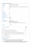
• Motor Rotates in the Opposite Direction from the Run Command
- t¥.'c~~\2£
~0~jj~Ciu.~~""'!i$l:~..'t.hR&')(,'1 aruii&'i?&~m~'E··\i£it,:;e:O$jiftili!$9tiiJionst,;·:::;""~~>!iZi'(·
o Check the motor wiring.
o Switch two motor cables (U. V. and W) to reverse motor direction.
Phase wiring between the drive and motor is incorrect. Connect drive output terminals UIr) •Vm and Wm in the right order to the corresponding
motor terminals U. V. and W•
• Change the setting ofparametcrbJ-J4.
Typically, forward is designated as being counterclockwise when looking from the motor
shaft (refer to the figure below).
"
0
1
~2
The forward direction for the motor is setup
incorrectly.
1. Forward Rotating Motor (Joo1dng dOWD the motor abaft)
2. Motor Shaft
The motor is nmning at almost 0 Hz and the Speed
Search estimated the speed to be in the opposite
direction.
o
Disable bi-dircctional search (b3-14 c
specified direction.
''OJ so that Speed Search is pcrfonned only in the
Note: Check the motor specifications for the forward and reverse directioDS. The motor specifications will vary depending on the manufacturer
of the motor.
• Motor Rotates in One Direction Only
• Motor is Too Hot
air around the motor is too hot
drive is operating in a vector control mode but
Tuning has not yet been perfonncd.
256
YASKAWA ElECTRIC SIEP C710606 16A YASKAWA AC Drive - Vi 000 Technical Manual
6.9 Troubleshooting without Fault Display
1;(iN:;!ff1;t].0~~-uiiJ?j{~jJ--83ts?'rti.'fi LLM~:~:±k;YISif:\7""~P,QSSlbJQj$pJU«O"ii['h:.~:~:3'::,I!]M[ffi::.~'·i«':,;
When the motor is connected to tenninals urn, v m, and Wm, voltage surges occur
between the motor coils and drive switching.
NOIDlally, surges can reach up to three times the drive input power supply voltage (600 V for
Insufficient voltage insulation between motor phases. 200 V class, and 1200 V for 400 V class).
• Use a motor with voltage tolenmce bigher than the max voltage surge.
• Usc a motor designed to work specifically with a drive when usiog a 400 V class unit
• Install an AC reactor 00 the outPut side of the drive.
The motor fan has stopped or is clogged.
Check the motor fan.
•
Drive Does Not Allow Selection of Rotational Auto-Tuning
:J~~l?i:c-austr,$:&;}::&'P;;:1':"~~";'lt's~;::r~~'ld\:.~~;p~m-~RCiii1lioc.SQ1UtiCiii$!5~kWFjj::?1J~kt'''lli;:,'i;'i:;Lr:f:''Y,--'~,,;:,-,(
The drive is in the ioco~motor • Check if the drive is set to V/fControl by accident (AI-02 = 0).
~::~~:d for Rotational
• Change the motor control method to Open Loop Vector Control (AI.02 '" "2").
•
Motor Hunting Occurs at Low Speeds
rIJir'f~>~.\)f!i1>:;qG3IeaUPJj1m~s'itiI~}j ~:ir:.%:ir';'.;i4iYi0;~&£n~0ji161il.a'QKi~liit>'i~tf:¥~$:;i(':¥i'i%iTJ[tS!1::::,Z:':-:
• Excess load inertia can cause motor bunting in Open Loop Vector Control due to slow motor
response.
Excessive load inertia in Open Loop Vector Control. • Increase the speed feedback detection control time constant (112-02) from its default value
of50 ms to an appropriate level between 200 and 1000 ms. Adjust this setting io combination
with 112-03 (Feedback Detection Centrol rune Constant 2).
•
Overvoltage Occurs When Running at a Constant Speed
IExcesrive load inertia in Open Loop Vector Control.
•
Motor Stalls During Acceleration or With Large Loads
.. ':.; ..
problem:
•
Motor Will Not Accelerate or the Acceleration Time is Too Long
IFJ'f!OUf:nCV reference is too low.
CD
c:
g
..c
::
• Check the torque limit setting. It may be too low. (L7·01 through L7-04).
• Reset the torque limit to its default value (2000A.).
:a:::I
!
if the acceleration time parameters have been set too long (CI-OI, -03, -05, -07).
~~~~j---------------------------~a
or A2 is sct for frequency gain (H3-02 or H3-10= "1"). If
voltage (current) input provided.
YASKAWA ELECTRIC SIEP C71060616A YASKAWAAC Drive - V1000 Technical Manual
257
6.9 Troubleshooting without Fault Display
be long enough (over so m) to require Autois comparatively limited when it comes to Dmduc:iD~ torque at low speeds.
Vcctor Control.
• Drive Frequency Reference Differs from the Controller Frequency Reference Command
~T1!F'Jill.!lIJ~Ciu8e)],.hl1JelFmimo/D [~~~~,·(:1i::0~7;Js17l'EiJ!ossll:ifi;.SOfUtlo~~g~ti,);,:~~~~~'}i:.&1Ji..W
• Check the main speed frequeocy reference terminal input gain level assigned to terminals
The analog input frequency gain and bias are set to
incorrect values.
Al and A2, as well as the frequency reference input bias to terminals A I and A2 (parameters
H3-03, H3-04, and H3-12).
Set these~arameters to the ~roj)riate values.
• Ifmulti-fimction analog input terminals Al and A2 are set for frequency reference (H3-02
A frequency bias signal is being entered via analog
=0 and m-Io a 0), the addition of both signals builds the frequency reference.
input terminals A I or Al.
• Ensure that H3-02 and 113-10 are set appropriately.
• Check the input level set fortermina1s Al and A2 (UI-U, Ul-14).
·
• Poor Speed Control Accuracy
IMcltor··nw~
voltage is set too high in Open Loop
Control.
properly for Open
• Deceleration Takes Longer Than Expected with Dynamic Braking Enabled
IlIlliUfiicie:nt motor torque.
the internal torque limit
drive rated current
• Motor Hunting Occurs When Operating With a Light Load
output frequency and the base
are Dot set properly in
to each
="1 .
Prevention is disabled CVlf control only).
258
reec:lbac:k detection control gain and time constant (02-0 I,
YASKAWA ElECTRIC SIEP C71060616A YASKAWA AC Drive - V1000 Technical Manual
6.9 Troubleshooting without Fault Display
• Load Falls When Brake Is Applied (Holst-Type Applications)
lV.~!~LJi~~~ICa~J'iK;'l¥-;'~~~~:s.:1ri!'tl!.G. '11E.~'ib~2Jifit:,~:i"~F::y,J:("TIr~;;;;':::'~()jilljI8lS.oJamcroS1~~,i~~"1'l$'~a:::::.~~%~i~)]!'';'~''
Use frequency reference detection for closing and releasing the brake.
• At start: Release the brake after creating enough torque.
• At stop: Close the brake when the motor still ~ torque.
Make the following setting changes to hold the
e:
• Set the frequency detection inactive during baseblock (L4-07 = 0).
The timing for the brake to close and release is not set • Multi-function contact output terminal will switch on wben the output freauency is greater
than the fi"equency detection level set in U-OJ. Set L4-O I between 1.0 an 3.0 Hz.
properly.
• SIi£pin8 may occur when stopping because hysteresis is used in Frequency Reference 2
(w ere the frequency agree setting in L4-02 is 2.0 Hz). To prevent this, change the setting
to 0.1 Hz.
• Do not use the multi-function contact output setting "During Run" (H2-01 "" 0) for the brake
siJmat.
Increase the amount of DC Iniection Brakine (b2-02).
Insufficient DC Injection Braking.
• Noise From Drive or Output Lines When the Drive is Powered On
~~~~
switching in the drive
Ige:olerates excessive noise.
• Ground Fault Circuit Interrupter (GFCI) Trips During Run
• Increase the GFCl sensitivity or use
wi1b a higher threshold.
• Lower the carrier frequency (C6-02).
• Reduce the length of the cable used between the drive and the motor.
• Install a noise filter or reactor on the
side orthe drive.
• Connected Machinery Vibrates When Motor Rotates
Excessive Motor Oscillation and Erratic Rotation
Unexpected Noise from Connected Machinery
Ilb~~ cIri'~ oU1put frequency is the same as the I'CS()DUlti
Ifrequcocyofthe connected machinery.
Note: The drive may have Irouble assessing the status of the load due to white noise generated when using Swing PWM (C6-02 = 7 to A).
• Oscillation or Hunting
IIDliUfficienl tuning in Open Loop Vector Control
frequency reference is assigned to an external
and the signal is noisy.
cable between the drive and motor is too long.
YASKAWA aECTRIC SIEP C71060616A YASKAWAAC Drive-V1000TedllllcaI Manual
259
6.9 Troubleshooting without Fault Display
• PID output fault
·O~
•
•
•
•
•
m~
~
Set multi-function analog inputtenninal Al or A2 for PlD feedback (H3-02 or ID-I 0 =
A signal input to the tc:rmina1 seJection for PID feedback is Dccessazy.
Oeck tbe connection of the feedback signal.
Check the various PID-related parameter settings.
No PID feedback input to the terminal causes the value detected to be 0, causing a PID
at max
level of detection and the target value do not
Icorrespond with each other.
• Insufficient Motor Torque
Auto-Tuning again.
Rotntional Auto-Tuning.
~~~----------~======~--------------~
• Motor Rotates After the Drive Output Is Shut Off
DC Injection BJ3king and the drive cannot
Idel:elerate properly.
• ov or Speed Loss Occurs When Starting Into a Rotating Load
•
• alreadv rotatin'g when the drive l'S trvl.... •
load
IS
start it
~
-~-.. •
•
Stop
bnWng. Restart the motor.
Increase the value
Injection Braking Time at start).
Enable Speed Search at
(b3-01 ="I").
Set a multi-function input tcnninaJ for external Speed Search command (H1-OO"'''61'' or
• Output Frequency Is not as High as Frequency Reference
• Buzzing Sound from Motor at 2 kHz
IExceeded 110% of the rated output current of the
while operating at low speeds.
• Unstable Motor Speed when Using PM or IPM
260
YASKAWA ELECTRIC SIEP C710B061BA YASKAWAAC Drive- V1000 Technical Manual
6.9 Troubleshooting without Fault Display
g,\~Qr",I5~8;',R;~:CWs"119%m;""2~;§G':'~: L0IJ.t:D:,:c::'3f>~1',k!£';Jj~~;';:~;,:Sjrt;\:e.~jillble1SQluttiir{sl;~:'15M"!1{S~':~Ji~1J.:~~~;
• H using a PM motor, set the correct motor code to ES-O I.
Too much current is flowing through the drive.
• Ifusing a specialized motor, set parameter ES·xx to the correct value according to the Motor
Test~
• Motor Does Not Operate When the RUN Button on the Digital Operator is Pressed
ru;;';:'~mC:'aUi8~4;;''i;;i:'2:Thjo:~ [~)'T;~::1~ljl~'%illillL~C:,f'fP,Q$slblaS(»JutlonSl[ir">:i{J'.'~,;:3;:~~:,:::J, '{}~~:f{}~;'
The LOCAlJREMOTE mode is not selected
Iproperly.
The drive is not in drive mode.
The frequency reference is too low.
Press the LOCAUREMOTE button to switch. The WIRE LED should be on for LOCAL
mode.
A run command will not be issued. Exit to the drive mode and cvcle the run command.
• If the frequency reference is set below the frequency set in EI-09 (Minimum Output
Frequency), the drive will not operate.
• Raise theJfieQueocy reference to at least the minimum outout frequency.
• Motor Does Not Operate When an External Run Command Is Input
ff2:i!1u;{;;:"'5(;SJ,C~~f;;a~~'5I1"i]:Li::l~j n:~G4i:\~",j:iii;{];iE:~ltossltilii$ORit~W'~iti~~[ij;:
The LOCALlllEMOTE mode is not selected
properly.
The drive is not in Drive Mode.
The frequency reference is too low.
Press the LOCAlJREMOTB button to switch. The LO/RB LED should be off for REMOTE
mode.
A nm command will not be issued. Exit to the Drive mode and cycle the run command.
• If the frequency Jeference is set below the frequency set in BI-09 (Minimum Output
frequencY), the drive will not operate.
• Raise the
reference to at least the minimum oulDUt frequency.
• Motor Stops During Acceleration or When a Load Is Connected
. i.;·
is too heavy.
• The limit of motor response mayfube~rea~~ch~ed~i:I~~::~ the acceleration time (CI-OI) or reduce the motor load. Also, consider increasing
rapid acceleration. This may be a
size and/or drive size.
stall
or automatic torque boost
• Motor Rotates In One Direction Only
.~
runprohtllited" is
Ifbl-04
l(RewenseProlullit Operation) is set to I (reverse run
IPrcllnllitecll), the drive will not accept a Jeverse run
"
b 1-04 .. "0" to allow reverse run operation.
• Motor Operates at a Higher Speed than the Speed Command
• Poor Speed Control Accuracy Above Base Speed In Open Loop Vector Motor Control
Method
.
"'
.:.
;"1.:.:.
a motor with a lower rated voltage compared to the input voltage.
==~~===-----~--------------------------~~
• Peripheral Devices Affected by Drive Operation
frequency
may be generated by
interference
output PWM waveform.
YASKAWA ELECTRIC SIEP C71060616A YM:.KAWA AC Drive - V1000 Technical Manual
261
6.9 Troubleshooting without Fault Display
• Ground Fault Interrupter Activates When Drive Is Running
The output of the drive is a series of high frequency • Chanlle. t~ a ground fault intenupter with a high~ I~ge curren! det~tion level (such as,
pulses (l>WM), 50 there is a certain amount ofleakage a senslhVlo/ current of20~ rnA or greater per U!Ht. Wlt!t an operatmg tune of 0.1 5 or more).
current This may cause the ground fault interrupter
or one that mcorporates high-frequency corrective achons.
to operate and cut off the drive input power
• Change the Camer Frequency Selection (C6-02) to lower the carrier frequency.
.
Note: Leakage curreot increases in proportion to cable length.
262
YASKAWA ELECTRIC SIEP C710S06 1SA YASKAWA AC Drive - V1000 Technical Manual
[Excerpted]
I-V Series AC Servo Drives USER'S MANUAL
Design and Maintenance
9
Troubleshooting
9.1 Alarm Displays ....................................•......... 9-2
9.1.1 List of Alarms •••••••••.••••••.•.•••••••••••••••••••••••.••.•.•....... 9-2
9.1.2 Troubleshooting of Alarms •••.••••••••••.•••.•.••.•••••.•••••.••••••••.• 9-6
9.2 Warning Displays ................•............•......•.•.•.. 9-21
9.2.1 Ust of Warnings •••.••••••••••••••••••••••••••••.••••••••••.•.•..••.• 9-21
9.2.2 Troubleshooting of Warnings ........................................... 9-22
9.3 Troubleshooting Malfunction Based on Operation
and Conditions of the Servomotor ...••.•........•..........•.• 9-26
9-1
9 Troubleshooting
9.1.1 List of A1anns
9.1
Alarm Displays
The following sections describe troubleshooting in response to alarm displays.
The alarm name, alarm meaning, alarm stopping method, and alarm reset capability are listed in order of the
alarm numbers in 9.1.1 List ofAlarms.
The causes of alarms and troubleshooting methods are provided in 9.1.2 Troubleshooting ofAlarms.
9.1.1
List of Alarms
This section provides list of alarms.
• Servomotor Stopping Method
If an alarm occurs. the servomotor can be stopped by doing either of the following operations.
Gr. 1: The servomotor is stopped according to the setting in PnOO 1.0 if an alarm occurs. PnOO 1.0 is filctoJ)'-set
to stop the servomotor by applying the DB.
Gr.2: The servomotor is stopped according to the setting in PnOOB.I if an alarm occurs. PnOOB.l is factory-set
to stop the servomotor by setting the speed reference to ~O. a The servomotor under torque control will
always use the Gr.l method to stop. By setting PnOOB.l to I, the servomotor stops using the same
method as Gr.l. When coordinating a number of servomotors, use this stopping method to prevent
machine damage that may result due to differences in the stop method.
• Alarm Reset
Available: Removing the cause of alarm and then executing the alann reset can clear the alarm.
Executing the alarm reset cannot clear the alarm.
NtA:
Gr. I
N/A
N/A
~I
9-2
Gr. I
N/A
Gr. I
N/A
Or. I
Available
After executing the utility function to tum ON the
power to the motor, the servo ON command (SV_ON)
was sent from the host controller.
Or.l
Available
An overcurrent Bowed through the IOBT or the heat
sink of the SERVOPACK was overheated.
Gr.t
N/A
9.1 A/ann Displays
(cont'd)
Available
N/A
The servomotor speed
tional speed.
above the
rota-
The pulse output speed upper limit ofthc set encoder
output pulse (P0212) is exceeded.
motor was
for several seconds to several
tens of seconds under a torque largely exceeding ratings.
under a torque
Gr.t
Available
Or,]
Available
Gr. I
Available
Or.2
Available
Gr.1
Available
Gr. I
Available
Available
Available
Available
Ol
c::
:g
External encoder is faulty.
Or.1
Available
The position data of external encoder is faulty.
Gr.1
Available
:c'":l
The ovcrspced ftom the external encoder occurred.
Gr.t
Available
.=
0
.r::.
GI
0
a
9-3
9 TroubleshooUng
9.1.1 Ust of Alarms
(cont'd)
Gr. I
N/A
"Intcmal program error O· of the SERVOPACK
occurred.
Gr.1
N/A
"Internal program error I" of the SERVOPACK
occurred.
"Intcma1 program error 2" olthe
occurred.
Gr.1
N/A
Gr.t
N/A
"Internal program error 3"
occurred.
Gr.1
N/A
Gr.t
N/A
The multitwn for the absolute encoder was not properly cleared or scl
Gr.t
N/A
Communications between the SERVOPACK and the
encoder is not possible.
Gr.1
N/A
An encoder position data ealculation error occurred.
Gr. I
N/A
An error occurs in the commIlIIications timer between
the encoder and the SERVOPACx..
Gr.1
N/A
Gr.1
N/A
Different multitum limits have been set in the encoder
and the SERVOPACK.
Gr.1
NlA
Reception from the Feedback Option Module is faulty.
Gr.1
N/A
nmcr for communications with the Feedback Option
Module is fiwlty.
Gr.J
N/A
This alarm occurs if the SV_ON command is received
wIleD the position error is greater dum the set value of
PnS26whiJc thescrvomotorpower is OFF.
Gr.1
Available
When the position error remain in the ener counter,
PnS29 limits the speed if the SV_ON command is
received. IfPnS29 limits the speed in such a state, this
alarm occurs when position rcfc:n:uces arc input and
the number of position ellOIS exceeds the value set for
the excessive position error alarm level (pnS20).
Gr.2
Available
During fuUy-closcd loop control, the position error
between motor and load is excessive.
Gr.2
Available
Synchronization error during MECHATROLINK.-ll
communications with the SERVOPACK.
Gr.1
Available
munications.
System Alann 2
Communications
Position Error Overflow
Alann by Speed UmH al
Servo ON
•
9-4
The alarm that may occur in a
with Fully-closed Module.
~
9.1 Alann Displays
(cont'd)
The setting of the MECHATROLINK-lltransmission
cycle is out of the allowable r.mge.
Or.2
Available
A synchronization error occurs during MECHATROLINK·D communications.
Gr.2
Available
A synchronization failure occurs in
TROLINK-D communications.
Or.2
Available
A communications error occurs continuously during
MECHATROLINK-D communications.
Gr.2
Available
The transmission cycle fJuctuates during MECHATROLINK-ll communications.
Or.2
Available
Detection of the Feedback Option Module failed.
Gr. I
N/A
A SERVOPACK DRV alann 0 occurs.
Gr.2
Available
The safety fUnction signal input timing is faulty.
Or. I
N/A
Gr.2
Available
Or.2
Available
error occ:urrcd when using a MECHAcommand.
With the main power supply ON, voltage was low for
more than 1 second in phase R, S, or T.
Digital operator (JUSP-OPOSA-I-E) fails to communicate with the SERVOPACK (e.g.. CPU error).
•
N/A
N/A
The alann that may occur in a SERVOPACK with Pully-c:losed Module.
•
9-5
9 Troubleshooting
9.1.2 Troubleshooting of Alarms
9.1.2 Troubleshooting of Alarms
If an error OCCUIS in servo drives, an alann display such as A.[][][J and CPF[][] will appear on the panel display.
Refer to the following table to identify the cause ofan alann and the action to be taken.
Contact your Yaskawa representative if the problem cannot be solved by the described corrective action.
9.1 Alann Displays
(cont'd)
A.041:
Encoder Output Pulse
Setting Error
A.042:
Parameter
Combination Error
Semi-closedlFullyclosed Loop Control
Parameter Setting
Error
A.D4A:
Parameter Setting
Ener2
operation
lower thaD the
setting range after having
changed the electronic gear ntio
(Pn20ElPn2I0) or the servomotor.
The
operation
thaD the
setting range after having
changed the setting of the progIlIID JOG movement speed
(PoS33).
The
speed
autotuning is lower thaD the set·
ling range after having changed
the electronic gear ratio (Pn20PJ
Pn210) or the servomOtor.
Check the parameter Pn212.
Set Pnll2 to a conect value.
Check that the detection condilions OJ are satisfied.
Decrease the setting of the electronic gear ntio (pD20ElPnlI 0).
Check that the detection conditions J are satisfied.
Increase the setting of the program
JOG movement speed cPoS33).
Check that the detection conditionsOJ are satisfied.
Decrease the setting of the electronic gear ntio (PD20ElPn21 0).
0
The setting of the fully-closed
module does not match with that Check the settings of PnOO2.3.
ofPnOO2.3.
The setting offully-closed module
must be compabble with the setting
ofPn002.3.
For a 4-byte parameter
no
registration in two consecutive
bytes for two bank members.
amount of bank data
exceeds 64. (Pn900 x Pn90I >
the number ofbytes for
banle members to an appropriate
value.
64)
Reduce the total amount ofbanlc
data to 64 or less.
Check the capacities to see
Select the proper combination of
The SERVOPACK and servomo- satisfy the following condition:
SERVOPACK and servomotor
A.050:
tor capacities do not match each
Servomotor capacJty
Combination Ener
cnher.
114 S SERVOPACK ciipiCft)' S 4 capacities.
(The SERVOPACK and t - - - - - - - - - - t = - - : - - - : - - - - - : - - - : - - - : - : : - t - - - - - - - - - servomotor capacities do An encoder fault oc:cuned.
servomotor and see if Replace the servomotor (encoder).
not conesponcL)
faulty.
A SERVOPACK fault occurred.
A.OS1:
Unsupported Device
Alarm
A.ObO:
canceUed Servo ON
Command Alarm
An unsupported serial converter
unit, encoder, or external encoder Check the product specifications,
is connected to the SERVOand select the cancet model.
PACK.
Select the conect combination of
units.
After
the
function to tum
the power to the
motor, the servo ON command
(SV_ON) was sent from the host
controller.
Tum the SERVOPACK power supply OFF and then ON again or execute a software resel
9-7
9 Troubleshooting
9.1.2 Troubleshooting of Alarms
Incorrect wiring or contact fault
of main circuit cable or servomotor main circuit cable.
Correct the wiring.
Short-eircuit or groWld fault of
main circuit cable or servomotor
main circuit cable.
The cable may be short-eircuited.
Replace the cable.
Short-circuit or ground fault
inside the servomotor.
across the
servomotor terminal phases U, V.
and W, or between the grounding
and servomotor tenninal phases U,
V, or W. Refer to 3. J Main Circuit
Short-circuit or ground fault
inside the SERVOPACK.
Check for short-circuits across the
scrvomotorconnectioD terminals U,
V. and W on the SERVOPACK, or The SERVOPACK may be faulty.
between the grounding and terminal Replace the SERVOPACK.
U, V. or W. Refer to 3. J Main Circuit Wiring.
The servomotor may be faulty.
Replace the servomotor.
Wiring.
A.100:
Overcurrent or Heat
Sink Overheated
(An ovcrcurrent flowed
througb the IGBT or
beat sink ofSERVOPACK overheated)
Incorrect wiring or contact fault
of the regenerative resistor.
The~cbnkeO)B:Emer-
geney stop executed from the
SERVOPACK) was frequently
activated, or the DB overload
alarm occurred
~
Correct the wiring.
DB
power
resistance (UnOOB) to sec bow
many times the DB has been used.
Or, check the alarm history display
FnOOO to see if the DB overload
alarm A.730 or A.731 was reported.
Change the SERVOPACK model,
operating conditions, or the mecbanism so that the DB does not Deed
to be used so frequently.
The generated regenerative resisCheck the operating condition
Check the regenerative load ratio
tor value exceeded the SERVO- (UDOOA) to see how many times the including overload, and reconsider
PACK. regenerative energy
regenerative resistor has been used the regenerative resistor value.
capacity.
The SERVOPACK regenerative
resistance is too small.
Check the regenerative load ntio
(UDOOA) to see how many times the
regenerative resistor has been used
A beavy load was applied while
the servomotor was stopped or
running at a low speed.
Check to see if the operating
lions are outside servo drive specifi·
cations.
Malfimctioo caused by noise
interference.
countenneasures
Improve the wiring or installation
such as correct wiring oftbe Fa
enWomnCJIt, such as by reducing
Use an FG wire size equivalent to
noise, and check to sec ifthc alarm the SERVOPACK main circuit wire
recurs.
size.
A SERVOPACK fault occurred.
'"""'1
Tum the power supply OFF and
then ON again. If the a1arm still
occurs. the SBRVOPACK may be
faulty. Replace the SERVOPACK..
9-8
9.1 AJann Displays
• Regenerative resistor
(pn600) is set to a value
than 0 for a SGDY-R70, -R90,
-I R6, -2R I, or -2R8 SERYOPACK, and an external regenerative resistor is oot
Check the cxternal regenerative
Connect the external regenerative
connected.
• An external regencrative resis- resistorconnectioo and the value of resistor, orsct Pn600 to 0 ifno
the Pn600.
regenerative resistor is required.
tor is not connected to the
SGDY-470, SGDV-SSO,
SGDY-S90, SGDV-780,
SGDY-210. SGDV-260,
SGDY-280, or SGDV-370
SERVOPACK..
A.300:
Regeneration Error
between the power supply terminals Correctly mount a jumper.
B2 andB3.
Check the external regenerative
resistor connection.
Correctly connect the external
regenerative resistor.
Measure the power supply voltage.
A.320:
RegeneraUve
Overioad
resistance, regenerative resistor
capacity, or SERYOPACK capacity.
Or, regenerative power has been
cootinuously flowing back.
power cootiouback because ncgawas continuously
Check the operatiog condition or
the ~ty using the capacity
selection Software SigmaJunmaSize+, etc.
Change the regenerative resistance,
regenerative resistor capllcity, or
SERYOPACK capacity. Reconsider
the opemting conditions using the
capacity selection software SigmalU11DU1Size+, etc.
th
. I .
Check the load applied to the servo- Reconsider e system me udmg
motor doring operation.
servo, machine, and operating COnditioDS.
regenerative
resistor connection and the value of Set the Pn600 to a correct value.
thePn600.
The extemel regenerative resistance is too high.
Check the regenerative resistance.
faulty.
A SERVOPACK fault occurred.
The regenerative resistor discoonccted wheo the SERYOPACK
power supply voltage was high.
A.330:
Main Circuit Power
Supply Wiring Error
(Detected when the
resistor
built in the
Measure the resistance of the regen- Replace the SERVOPACK..
erative resistor using a measuring
When using an external regenerainstrument.
tive resistor:
Replace the cxternal regenerative
resistor.
~~~~~~~~iji8citi,-t~~~===::=:;::;-:-~~~~~~~~~~~~~
Check if regenerative resistor is
is turned
ON.)
to the
main circuit ~
power
connected and check the regenerative resistor capacity.
A SERYOPACK fault occurred
faulty.
9-9
9 Troubleshooting
9.1.2 Troubleshooting of AJanns
(cont'd)
• For
SERVOPACKs:
The AC power supply voltage
exceeded 145 V.
• For 200-VAC SERVOPACKs:
The AC power supply voltage
exceeded 290 V.
• For400-VAC SERVOPACKs:
The AC power supply voltage
exceeded 580 V.
• For 200-VAC SERVOPACKs:
with DC power supply input:
The DC power supply voltage
exceeded 410 V.
• For 400-VAC SERVOPACKs:
The DC power supply voltage
exceeded 820 V.
The power supply is unstable, or
was influenced by a lightning
surge.
A.400:
OvelVoltage
(DdccIcd in the SER-
VOPACK maio circuit
power supply section.)
AcceleratioDldeceleration was
executed under the fonowing
conditions.
• The AC power supply voltage
of lOO-VAC SERVOPACK
was in the range between II S
V and 13SV.
• The AC power supply voltage
of200-VAC SERVOPACK
was in the range between 230
V and 270 V.
• The AC power supply voltage
Measure the power supply voltage.
Set ACIDC power supply voltage
within the specified range.
Measure the power supply voltage.
Improve
power
tions by installing a surge absorber,
etc. Then, tum the power supply
OFF and ON again. Ifthe alarm still
occurs, the SERVOPACK may be
faulty. Replace the SERVOPACK.
Check the power supply voltage and Set AC power supply voltage within
the speed and torque during opera- the specified range.
lion.
of~VACSERVOPACK
was in the range between 480
V and 560 V.
cxtcmal regenerative
lance is too higb for the actual
operating conditions.
The moment
exceeded the
Select a regenerative resistance
Check the operating conditions and vaIuc appropriate for the operating
the regenerative resistance.
conditions
load.
or
Tum the control power OFF and
then ON again while the main cirA SERVOPACK fault 0CCUJTCd.
9-10
cuit power supply is OFF. If the
alum still occurs, Ihe SERVOPACK may be faulty. Replace the
SERVOPACK.
9.1 Alarm Displays
A.41 0:
Undervoltage
(Detected in the SERVOPACK main circuit
power supply section.)
• For 100-VAC
Thc AC power supply voltage
is 49 V or less•
• For200-VAC SERVOPACKs:
The AC power supply vollage
is 120 V or less.
• For 400-VAC SERVOPACKs:
The AC power supply voltage
is 240 V or less.
Measure the power supply voltage.
Set the power supply voltage within
thc specified range.
Thc power supply voltage
dropped during operation.
Measure the power supply voltagc.
Increase the power supply capacity.
OCCUlTCDce of instantaneous
power interruption.
Measure the power supply voltage.
When the instantaneous power cut
hold time (PnS09) is set, decrease
the setting.
Replace the SERVOPACK, connect a reactor, and run the SERVO.
PACK.
The SERVOPACK fuse is blown
out
faulty.
A SERVOPACK fault occwred.
A SERVOPACK fault occwred.
Main-Circuit
Capacitor Overvoitage
order
U, V,andW
in the &elVomotor wiring is incor- Check the servomotor wiring.
recl
A.51 0:
Overspeed
(IlIe servomotor rotational speed exceeds the
maximum.)
A reference value exceeding the
ovcmpeed detection level was
input
Check the input value.
The motor speed exceeded the
maximum.
Check the servomotor speed waveform.
A SERVOPACK fault occwred.
("'
A.S11:
Overspeed of Encoder The encoder output pulse output
frequency exceeded the limit
Output Pulse Rate
because the servomotor speed
was too high.
A.520:
Vibration Alann
A.521:
Autotuning Alann
{Vibration was detected
while executing the
advanced autotuning,
one-parameter tuning,
EasyFFT, or tuning-less
function.)
Chcdcthe
ling.
Replace the SERVOPACK.
Confirm that the servomotor is corrcctIy wired.
Reduce the reference value or adjust
the gain.
The SERVOPACK may be faulty.
Replace the SERVOPACK.
output pulse setencodcr
output
Check the encoder output pulse outDecrease the servomotor speed.
put setting and servomotor speed.
Check for abnormal noise from the
Abnormal vibration was detected sClVomotor, and check the speed
at the SClVomotor speed.
and torque waveforms during operalion.
The moment of inertia ratio
(Pn103) value is greater than the
Check the moment of inertia ratio.
actual value or is greatly
changed.
Reduce the SClVomotor speed or
reduce the speed loop gain (pnlOO).
Set the moment of inertia ratio
(PnI03) to an appropriate value.
en
The servomotor vibrated considerably while perfonning tuningless function (factory setting).
Check the servomotor speed waveform.
the
moment
of inertia ratio falls within the
allowable value, or raise the tuning
level using the tuning-less levels
setting (F0200) or reduce the load
level.
The servomotor vibrated considerably during advanced autotuning, one-parameter tuning, or
EasyFFT.
Check the servomotor speed waveform.
Check the operation procedure of
corresponding function and take a
corrective action.
c
~
0
~
III
III
:is
:::J
.....e
EI
9-11
9 Troubleshooting
9.1.2 Troubleshooting of Alarms
(conrd)
Confinn that the servomotor and
encoder are correc:1ly wired.
A.710:
A.720:
Overload
A.710: High Load
A.720: Low Load
conditions and
the
operating conditions. Or, increase
the servomotor capacity.
Operation beyond the overload
protection characteristics.
Excessive load was applied during operation because the servomotor was Dot driven due to
mechanical problems.
Check the executed operation refer- Remove the mechanical problems.
ence and servomotor speed.
A SERVOPACK fault occurred.
The servomotor rotates because
of exteml11 force.
Check the operation status.
A.730:
A.731:
Dynamic Brake
The rotating enctgy at a DB stop Check the power consumed by DB
Overload
exceeds the DB JeSistance capac- resistance (UnOOB) to see how
(An excessive power
ity.
many times the DB has been used.
consumption ofdynamie
brake was detected.)
Take measures to ensure the servomotor will not rotate because of
external force.
Reconsider the following:
• Reduce the servomotor reference
speed.
• Reduce the moment of inertia
ratio.
• Reduce the number of times of
the DB stop operatioD.
~
A SERVOPACK fault occuned.
The
currcnt
operation frcqucncy at the main
Overload of Surge
circuit power supply ON/OFF
Current Umlt Resistor operation exceeds the allowable
(The main circuit power range.
is tumed ON/OFF too
frequently.)
A SERVOPACK fault occurred.
A.740:
The surrounding air temperature
istoobigb.
tun: using a thermostal
The overload alarm has been
reset by turning OFF the power
too many times.
display
Check the alarm
(FnODO) to see if the overload l11ann Change the method for resetting the
alarm.
was reported.
A7AO:
Heat Sink Overheated Excessive load or operation
(Detected when the heat beyond the regenerative energy
processing capacity.
sink temperature
exceeds lOODC.)
tion orientation orland insufficient space around the
SERVOPACK.
Check the surrounding air tempera-
the
ratio
(UnOO9) to see the load during operReconsider the load and operating
ation, and the regenerative load
conditions.
ratio (UnOOA) to sec the regenerative cnczgy processing capacity.
Check the SERVOPACK insta1Ja.
tion conditions.
Install tbe SERVOPACK correctly
as specified.
A SERVOPACK fault 0CCWTed.
A.7AB:
Built-In Fan In
SERVOPACK
Stopped
9-12
Tho fan inside the SERVOPACK Check for foreign matter or debris
stopped.
inside the SERVOPACK.
Remove foreign matter or debris
from the SERVOPACK. If the
alarm stin occurs, tho SERVOPACK may be faulty. Replace tho
SERVOPACK.
"""'\
9.1 A1ann Displays
(cont'd)
Set up the encoder (Fn008).
Check to
tumedON
A.810:
The power from both
control
Encoder Backup Error power supply (+5 V) from the
(Only when an absolute SERVOPACK and the battery
encoder is connected.)
power supply is not being sup(Detected on the encoder plied.
side.)
was
Confum the connection and set up
the encoder (FnOO8).
Replace the battery or Ialce similar
measures to supply power to the
tel}' or the connector contact status. encoder, and set up the encoder
(FnOOS).
Check the encoder connector bat-
~=--------+-------------tmi::-::i:;;-;:C":n:D:;;:ottibc;;;;re;'sct;:::;jb~Y:-;sct;t:"-An absolute encoder fiwlt
occurred.
tinS up the encoder again, replace
A SERVOPACK fault occurred.
The SERVOPACK may be faulty.
Replace the SERVOPACK.
the servomotor.
again using
Set up the
Fn008. If the alarm still occurs. the
An encoder Cault occurred..
servomotor may be faulty. Replace
the servomotor.
(Detected on the encoder 1 - - - - - - - - - - + - - - - - - - - - - - - i ' T h ; : : - e
side.)
A SERVOPACK Cault occurred.
Replace the SERVOPACK.
A.820:
Encoder Checksum
Error
~SE~RnV"oup.iA'A:cCKX;m;;;a;ybbe;&fa:;;julihty-;:.
The battery connection is incorCheck the battery connection.
rect.
Absolute Encoder
The battery voltage is lower than
Battery Error
Measure the battery voltage.
(The absolute encoder
the specified value 2.7 V.
battery voltage is lower
than the specified value.) A SERVOPACK fault occurred.
A.830:
The encoder malfunctioned.
A.840:
Encoder Data Error
(Detected on the encoder
side.)
Malfunction of encoder because
of noise interference, etc.
Reconnect the battery.
Replace the battery.
The SERVOPACK may be faulty.
Replace the SERVOPACK.
Tum the power supply OFF and
then ON again. Ifthc alarm still
occurs. the servomotor may be
faulty. Replace the servomotor.
encoder by separating the en~~
cable from the servomotor mam Circuit cable or by checking the
grounding and olber wiring.
The servomotor was running at
200 min-lor higher when the
control power supply was turned
ON.
9-13
9 Troubleshooting
9.1.2 Troubleshooting of Alarms
(cont'd)
=='-""""
The
operating tempera.
ture around the servomotor is too
high.
The servomotor load must be within
the specified range.
The servomotor load is greater
A.S60:
than the rated load.
Encoder OVerheated
(Only when an absolute
encoder is connected.)
An encoder fault occurred.
(Detected on the encoder
side.)
A.8AO"2:
Extemal Encoder
Error
A.8A1 "2:
External Encoder
Error of Module
A.8A2."2:
Extemal Encoder
Error of Sensor
(Incremental)
Turn the power supply OFF and
then ON again. If the alarm still
occurs. the servomotor may be
faulty. Replace the servomotor.
A SERVOPACK. fault occurred.
Tum the power supply OFF and
then ON again. If the alarm still
occurs. the SERVOPACK may be
faulty. Replace the SERVOPACK..
Before setting the zero point posiSetting the zero point position of
tion, use the fUlly-closed feedback
external absolute encoder failed pulse counter (UnOOE) to confirm
because the servomotor rotated.
that the servomotor is not rotating.
The servomotor must be stopped
while setting the zero point position.
An external encoder fault
Replace the extemaJ encoder.
occurred.
An external encoder fault
occurred.
Replace the extemaJ encoder.
A serial converter unit fault
occurred.
Replace the serial converter unit.
An extemal encoder fault
Replace the external encoder.
occurred.
A.8A3"2:
Extemal Encoder
Error of Position
(Absolute)
An cxtemal absolute encoder
fault 0CCUJ1'Cd.
A.8A5"2:
Extemal Encoder
Overspead
The overspced from the external
encoder occurred.
A.8A6"2:
Extemal Encoder
Overheated
The overheat from the cxtemaI
encoder occurred.
A.b31:
Current Detection
Error 1
The cwrent detection circuit for
phase U is faulty.
A.b32:
Current Detection
Error 2
The current detection circuit for
phase V is faulty.
The extcmal absolute encoder may
be faulty. Refer to the encoder man·
ufacturer's instruction I1I8IIU8l for
corrective actions.
Check the maximum speed of the
external encoder.
Keep the external encoder below its
maximum speed.
Replace the external encoder.
Tum the power supply OFF and
then ON again. If the alarm still
occurs, the SERVOPACK. may be
faulty. Replace the SERVOPACK.
power supply
and
then ON again. If the alarm still
occurs, the SERVOPACK. may be
faulty. Replace the SERVOPACK..
Tum the power supply OFF and
A.b33:
Current Detection
Error 3
The servomotor main circuit
cable is disconnected.
A.b6A:
SERVOPACK MECHAMECHATROLINK
TROUNK communication sccCommunlcaUonsASIC tion fault
Error 1
-2. The alarm that may occur in a
9-14
then ON again. If the alarm still
occurs, the SERVOPACK may be
faulty. Replace the SERVOPACK.
The detection circuit for the current is faulty.
Check for disconnection of the serCorrect the servomotor wiring.
vomotor main circuit cable.
Replace the SERVOPACK..
with
Module.
,
~
9.1 Alarm Displays
(confd)
A.bFO:
System A1ann 0
A SERVOPACK fault occurred.
A.bF1:
System A1ann 1
A SERVOPACK fault occuned.
A.bF2:
System Alann 2
A SERVOPACK. fault occurred.
A.bF3:
System A1ann 3
A SERVOPACK. fault occurred.
A.bF4:
System A1ann 4
A SERVOPACK fault OCCUlTed.
The
ofpbases U, V, and W
in the servomotor wiring is incor- Check the servomotor wiring.
rcct.
A.C10:
Servo Ovenun
Detected
An encoder fault occurred.
(Detected when the
servomotor power is
ON.)
A SERVOPACK fault occurred.
A.cao:
An encoder fault occurred.
Absolute Encoder
Clear Error and Multiturn Umit Setting Error A SERVOPACK fault occurred.
Turn the power supply OFF and
then ON again.lfthe alarm still
occurs, the SERVOPACK JDay be
faulty. Replace the SERVOPACK.
Tum the power supply OFF and
then ON again. If the aJann still
occurs, the SERVOPACK may be
faulty. Replace the SERVOPACK.
Turn the power supply OFF and
then ON again.lfthe alarm still
occurs, the SERVOPACK may be
faulty. Replace the SERVOPACK.
Tum the power supply OFF and
then ON again. If the alarm still
occurs, the SERVOPACK may be
faulty. Replace the SERVOPACK.
Confirm that the servomotor is correctlywired.
alarm still occurs after turning
the power OFF and then ON again,
even though the servomotor is correctly wired, thIS servomotor may be
faulty. Replace the servomotor.
Tum the power
thco ON again.
alarm still
occurs, the SERVOPACK may be
faulty. Replace the SERVOPACK..
Tum the
then ON again.
alarm still
occurs, the servomotor may be
faulty. Replace the servomotor.
Turn the
then ON again.
alarm still
occurs, the SERVOPACK may be
faulty. Replace the SERVOPACK..
9-15
9 Troubleshooling
9.1.2 Troubleshootlng or Alarms
(cont'd)
9-16
9.1 Alarm Displays
Noise interference occurred due
to incorrect encoder cable spcciti
cations.
A.CbO:
Encoder Echoback
Error
Noise
occurred
because the wiring distance for
the encoder cable is too long.
The FG potential varies because
of influence from machines on
the servomotor side, such as the
welder.
~
--
Use tinned annealed copper
shielded twisted-pair or screened
unshielded twisted-pair cable with a
core ofat least 0.12 mm2•
The wiring distance must be SO m
max.
Check the encoder cable layout.
Properly ground the machines to
separate from encoder FG
Check the operating environment.
\
A1l encoder fault occurred.
power
then ON again. If the alarm still
occurs, the SERVOPACK may be
faulty. Replace the SERVOPACK.
A SEllVOPACK fault occuned.
Check the value of the Pn205.
A.CCO:
Multiium Umil
Disagreement
~
of the
encoder is differeDt from that of
the SERVOPACK. Or, the multi- Check ebe value ofthe Pn205 of the Execute FoOl3 at the oc:cwrence of
SERVOPACK.
alarm.
turn timitvaluc of the SERVOPACK has been changed.
Turn the power supply
and
then ON again. If the alarm still
A SERVOPACK fault occurred.
occurs, the SERVOPACK may be
faulty. Replace the SERVOPACK..
of cable between serial
coDverterWlit and SERVOPACK
is incorrect or contact is faulty.
The specified cable is not used
A.CF1"2:
between serial converter unit and
Feedback Option
SERVOPACK..
Module
Communications Error Cable between serial converter
unit and SERVOPACK is too
(Reception error)
long.
A.CF2·2:
Feedback Option
Module
Communications Error
(Timer stop)
Correct the setting of Pn205 (0 to
6553S).
Check the cxternal encoder wiriog.
Correct the cable wiring.
Confirm the external encoder wiring specifications.
Use the specified cable.
Measure the length of this cable.
Use 2O-m cable max.
of cable between serial
coDverterWlit and SERVOPACK Check the cable for damage.
is broken.
Replace the cable.
Noise interferes with the cable
between serial converter unit and
SERVOPACK.
wiring around serial
Correct
converter unit, e.g., separating vo
signal line from main circuit cable
or grounding.
-
C)
c
:;:I
8
.r.
In
CD
:E
~
~
Ell
9-17
9 Troubleshooting
9.1.2 Troubleshooting of Alarms
(cont'd)
The servomotor U, V. and W wir- Check the servomotor main circuit
cable ronDection.
ings is faulty.
The position reference speed is
toohigb.
A.dOO:
Position Error
Overflow
The position reference accelera(Position error exceeded tion is too fasl
the value set in the
excessive position error
alarm levcl(Pn520).)
Setting of the excessive poSition
error alarm level (Pn520) is low
against the operating roodition.
Reduce the reference speed, and
operate the SERVOPACK.
Reduce the reference acceleration,
and operate the SERVOPACK.
(PnS20}tn
sce if it is set to an appropriate
value.
the position reference speed
or acceleration of position reference. Or, reconsider !he el~nic
gear ratio.
Reduce the reference acceleration
of the position reference using a
MECHATROLINK command, or
smooth the acceleration of the position reference by selecting the position reference filter (ACCFlL)
using a MECHATROLINK rommand.
~
I
Set the PnS20 to proper value.
Tum the power supply OFF and
then ON again. If the alarm still
occurs, the SERVOPACK may be
faulty. Replace the SERVOPACK.
A SERVOPACK fault occurred.
A.d01:
Position Error
Overflow Alarm at
Servo ON
A.d02:
Position Error
Overflow Alarm by
Speed Umlt at Servo
ON
Ad10"2:
Motor-load Position
Error Overflow
A.E02:
MECHATROLlNK-n
Intemal
Synchronization
Error 1
This alarm 0CCW1I if the SV ON
rommand is received when the
Check the position error amount
position error is greater than the (11nOO8) while the servomotor
set value of Pn526 while the ser- powee is OFF.
vomotor power is OFF.
position error remain in
When
the error rountcr, Pn529 limits
the speed if the SV_ON command is received. IfPnS29 limits
the speed in such a state, this
aJarm OCCUJS when position references are input and the number of
position errors exceeds the value
set for the excessive position
cuor alarm level (Pn520).
Motor rotation direction and
external enroder installation
direction are opposite.
Check the servomotnr rotation
direction and the ex1ema1 encoder
installation direction.
load (e.g., stage)
and extcmaI encoder joint instal- Check the external enroder
mechanical connection.
lalion are incorrect.
A parameter was
digital operator or the personal
computer during MECHATROLINK·n communications.
MECHATROLINK-D transmission cycle fluctuated.
Correct the excessive position error
alarm level (PnS20).
Or, adjust the speed limit level at
servo ON (PnS29).
external encoder in the
opposite direction, or change the
setting of the external encoder
usage method (pnOO2.3) to reverse
the direction.
Check the mechanical joints.
parameters
Stop
Confum the way the parameters are digital operator or persona1 romputet during MECHATROLINK-ll
edited.
rommunications.
Tum the power supply OFF and
A SERVOPACK fault occurred.
Setting of MECHATROLlNK-lI
Check the MECHATROLINK-ll
MECHATROLINK-D
transmission cycle is out of specitransmission cycle setting.
Transmission Cycle
fications range.
Setting Error
with Fully-closed Module.
·2. The alarm that may occur in a
9-18
Correct the excessive position error
alarm level at servo ON (Pn526).
then ON again. If the alann still
occurs, the SERVOPACK may be
faulty. Replace the SERVOPACK.
Set the transmission cycle to the
proper value.
~
9.1 Alarm Displays
A.E50:
MECHATROLlNK·lI
Synchronization Error A SERVOPACK fault occurred.
Tum the power supply
then ON again. lithe alarm still
occurs. the SERVOPACK may be
faulty. Replace the SERVOPACK..
data ofhost controller was
not updated correctly at the syn-
A.E5l:
MECHATROLlNK-lI
Synchronization
chronization communications
start, and synchronization com·
Check the WDT data updating for
the host controller.
Update the WDT data 3t the host
controller correctly.
munications could not start.
Tum the power supply OFF and
then ON again. lithe alarm still
occurs, Ihe SERVOPACK may be
faulty. Replace the SERVOPACK..
Failed
A SERVOPACK fault occurred.
MECHATROLINK·n wiring is
incorrect.
Check the MECHATROLINK·II
wirings.
A.E60:
MECHATROLINK-ll data recepMECHATROUNK-ll
tion error occurred due to noise Communications error interference.
(Reception error)
A SERVOPACK fault occurred.
A.E6l:
MECHATROLINK-Il
Transmission Cycle
Error
(Synchronization
interval error)
measures
noise. Check
the MECHATROLINK·D communications cable and FO wiring and
take measures such as adding ferrite
core on Ihe MECHATROLlNK.-1I
communications cable.
Turn the power supply
and
then ON again. Iflhe alarm still
occurs, the SERVOPACK may be
faulty. Replace the SERVO PACK.
Removetbe
cycle fluctuation
Tum
power
and
then ON again. If the alarm still
occurs. the SERVOPACK may be
faulty. Replace the SERVOPACK.
Correctly connect the Feedback
Option Module.
A.E72'?:
Feedback Option
Module Detection
Failure
The Feedback Option Module
WIIS disconnected.
Execute resetting
enor in option modules (FnO 14) and
turn the power supply OFF and then
ON again.
A Feedback Option
Replace the Feedback Option Module.
fault
occurred.
ConflnD the way Ihe parameters are
edited.
A.EA2:
DRVAlarm2
(SERVOPACK woe
error)
controller.
A SERVOPACK fault occurred.
*2. The alarm
Tum the power supply OFF and
then ON again.lfthe alann still
occurs, the SERVOPACK may be
faulty. Replace the SERYOPACK..
may occur in a SERVOPACK with rUI,ly-c:losc:a Module.
9-19
9 Troubleshooting
9.1.2 Troubleshooting of Alarms
(cont'd)
The output SIgnal circuits or devices
forlHWBBl and
The lag between activations of
Measure the time lag between the I
A.Eb1:
the input signals /HWBBt and
Safety Function Signal IHWBB2 for the HWBB function HWBBJand
IHWBB2 signals.
Input Timing Error
is ten second or mon:o
A.ED1:
Command Execution
Timeout
A timeout error occurred when
using an MECHATROLINK
command.
Check the motor status when the
command is executed.
Check the external encoder status
when the command is executed.
The three-pbase power supply
Check the power supply wiring.
wiring is incorrect.
A.Fi0:
The thn:e-phasc power supply
Main Circuit Cable
unbalanced.
Open Phase
(With the main power
A single-phase power
supply ON, voltage was without setting PnOOB.2 (power
Check the power supply and the
low for more than 1 sec- supply method for three-phase
parameter setting.
ond in an It. S, orT
SERVOPACK) to J (single-phase
phase.)
power supply).
(Detected when the main
power supply was IUmcd
ON.)
A SERVOPACK rault occurred.
CPFOO:
Digital Operator
Transmission Error 1
The contact betwccu the digital
operator and the SERVOPACK. is Check the connector contact.
faulty.
caused by
A digital operator fault occurred.
CPFOi:
Digital Operator
Transmission Error 2
-
~B20rtheSERVOPACK
input signal circuits may be faulty.
Alternatively, the input signal
cables may be disconnected. Check
if any of these items are faulty or
have been disconnected.
Execute
SV_ONor SENS_ON
command only when the motor is
not running.
Execute the SENS ON command
only when an external scale is connected.
Confirm that the power
is
correctly wired.
Balance the power supply by changingphases.
Match the parameter setting to the
power supply.
Tum the power supply OFF and
then ON again. If the alarm still
occurs, the SERVOPACK. may be
faulty. Replace the SERVOPACK.
Insert secun:ly the connector or
replace the cable.
Keep
operator or the
cable
noise sources.
Disconnect the digital operator and
then rc-connect it. If the alum still
oceurs, the digital operator may be
faulty. Replace the digital operator.
Tum the power supply OFF and
A SERVOPACK fault occurred.
then ON again.Ifthc alarm still
occurs, the SERVOPACK. may be
faulty. Replace the SERVOPACK.
9-20
~
9.2 Waming Displays
9.2
Warning Displays
The following sections describe troubleshooting in response to warning displays.
The warning name and warning meaning are listed in order of the warning numbers in 9.2.1 List o/Warnings.
The causes of warnings and troubleshooting methods are provided in 9.2.2 Troubleshooting oj Warnings.
9.2.1
List of Warnings
This section provides list ofwamings.
Position error exceeded the parameter setting
(Pn520xPnS1 ElIOO).
When the servomotor power turns ON, the position error exceeded the
parameter seumg (PnS26xPnS28I100).
Regenerative Overload
This warning OCCUIS before the regenerative overload alarm (A.320) occutS.
If the warniDg is ignored and operation continues. a regenerative overload
alarm may occur.
Dynamic Brake Overload
encoder's battCty is lowIncorrect command parameter number was set.
Command input data is out of range.
Calculation enor was detected.
Data size does not match.
Latch mode error is detected.
Command was sent although the conditions for sending a
satisfied
were not
Unsupported command was sent.
Command, especially latch command, interferes.
Subcommand and main command interfere.
Undefined command was sent.
Communications error occurred during MECHATROLINK communications.
This warniDg OCCUIS berore uDdervoltage alarm (A410) occurs. If the warning is ignored and operation conliDues. an undervo)tage alarm may occur.
Note: IfPoOOB.2" 1 (does not detect warning) is selected, DO warnings will be detected except for an undervoltage warning (A.97 I).
9-21
9 Troubleshooting
9.2.2 Troubleshooting of Wamings
9.2.2 Troubleshooting of Warnings
Refer to the foUowing table to identity the cause ofa warning and the action to be taken. Contact your
Yaskawa representative if the problem cannot be solved by the descn"bed corrective action.
A.900:
Position Error
Overflow
A.901:
Position Error
Overflow Alarm
at Servo ON
The servomotor U, V.
Check the servomotor main circuit
and W wirings is faulty. cable connection.
Confum that 1herc is DO contact fault
in 1he motor wiring or encoder wiring.
The SERVOPACK gain Check the SER.VOPACK ..,.in
is too low.
--
Increase the servo gain by using the
function such as advanced autotuning.
The position reference
acceleration is too fast
Apply the
such as
acceleraReduce the reference acceleration, and using the position
tion/deceleration time coDS1ant
operate the SERVOPACK..
(Pn216).
Setting of the excessive
position error alann
Check the alarm level (PnS20) to see
level (PnS20) is low
if it is set to an appropriate value.
against the operating
condition.
Set the PnS20 to proper value.
A SERVOPACK fault
occuned.
Turn the power supply OFF and then
ON again. lfthe alann still occurs, the
SERVOPACK may be faulty. Replace
the SERVOPACK..
When the servomotor
power turns ON, the
position error exceeded the parameter setting
(PnS26xPn52811oo).
Incorrect wiring or contact fault of servomotor
Check the wiriDg.
and encoder.
A.910:
Overtoad
(Waming befon:
alarm A. 71 0 or
A.720 occurs)
Operation beyond the
overload protection
characteristics.
Check the servomotor overload characteristics and executed run command.
Vibration
9-22
Con1irm that the servomotor and
encoder arc correctly wired.
operating conditions. Or, increase the
servomotor capacity.
Excessive load was
applied during operation because the servo- Check the executed operation refermotor was not driven
ence and servomotor speed.
due to mechanical problems.
Removo the mechanical problems.
A SERVOPACK fault
occurred.
The SERVOPACK may be faulty.
Replace the SERVOPACK..
Abnonnal vibration was Check for abnormal noise from the
detected while 1he scr- servomotor, and check the speed and
vomotor is rotating.
torque waveforms during operation.
A.911:
Correct the excessive position error
warning level at servo ON (PnS28).
The moment of inertia
ratio (Pol 03) value is
greater than the actual
value or is greatly
changed
Check the moment ofincrtia ratio.
Reduce the servomotor speed or
~thescrvogainbyusmgthe
function such as one-parameter tuIIing.
Set the moment of inertia ratio
(Pnl03) to an appropriate value.
9.2 Wamlng Displays
(cont'd)
A.920:
Regenerative
Overload
(Warning before
the alarm A.320
occurs)
~
A.921:
Dynamic Brake
Overload
(Warning before
the alarm A. 73]
occurs)
Absolute
Encoder Battery
Error
(lbe absolute
encoder battery
voltage is lower
than the specified
The power supply voltage exceeds the speci- Measure the power supply voltage.
tied limit.
Set the power supply voltage within
the specified range.
Insufficient external
regenerative resistance,
regenerative resistor
Check the operating condition or the
capacity, or SERVOcapacity using the capacity selection
PACK capacity.
Software SigmaJunmaSize+, etc.
Or, regenerative power
has been continuously
Howing back.
Change the regenerative resistance,
regenerative resistor capacity, or SERVOPACK. capacity. Reconsider the
operating conditions using the capacily selection software SigmaJunmaSize+, etc.
Regenerative power
continuously flowed
back because ncgative
load was continuously
applied.
Check the load to the servomotor dur- Reconsider the system including
serto, machine, and operating condiing operation.
lions.
The servomotor rotates
because of external
force.
Check the operation status.
The rotating energy at a Check the power consumed by DB
DB stop exceeds the DB resistance (UIIOOB) to see how many
times the DB bas been used.
resistance capacity.
Reconsider the following:
• Reducc the servomotor reference
speed.
• Reduce the mOmez1t of inertia ratio.
• Reduce the number of times of the
DB stop operation.
A SERVOPAClC fault
occurred.
The SERVOPACK may be faulty.
Replace the SERVOPACK.
The battery connection
is incorrect.
Check the battery connection.
The battery voltage is
lower than the specified Measure the battery voltage.
valuc 2.7 Y.
A.948
Data Setting
Waming2
(Out of Range)
A.94C
Data Setting
Wamlng 3
(Calculation
Error)
Reconnect the battery.
Replace the battery.
The SERVOPACK may be faulty.
Replace the SERVOPACK.
A SERVOPACK fault
occurred.
• Only when an
absolute encoder
is connected.
value.)
Data Setting
Waming 1
(paTcllDeter NumberEuor)
measures to ensure
servomotor will not rotate because of external
force.
Disabled parameter
number was used.
Use the correct parameter number.
Attempted to send vaIues outside the range to
the command data.
Set the value of the pammeter within
the allowable range.
-
CII
c
S
.s:;
U)
CD
:c::J
Calculation result of set
value is incorrect
Set the value of the plll1lJ1\eter within
the allowable range.
e
I-'
D
9-23
9 Troubleshooling
9.2.2 Troubleshooting of Warnings
(conl'd)
Data Setting
Warning 4
Parameter size set in
command is incom:ct.
Usc the com:ct parameter size.
Latch mode error is
detected.
Change the scuing value: of Pn8S0 or
the LT MOD data for the
LTMOD ON command sent by the
host controller to the proper value.
Command sending CODdition is Dot satisfied.
Send a command after coaunand
sending conditioD is satisfied.
SERVOPACK. received
unsupported command.
Do not sent an unsupported command.
(PataDlCtCl Size)
Data Setting
WarningS
(Latch mode
error)
Command
Warning 1
(UnsatistYiug
Command)
A95B
Command
Warning 2
(Non-supported
Command)
Command
Waming4
(Command Interference)
Command
WamlngS
(Subcommand
Disable)
Command sending CODdition for bltcb-related
commands is oot satis-
Send a command after command
sending condition is satisfied.
fied.
Subcommand sending
condition is not satis-
Send a command after command
sending condition is satisfied.
fied.
A.95F
Command
Warning 6
(Undefined Command)
Uodefinedcoaunand
was SCIlt
Do Dot usc an undefined command.
Concet the MECHATROLINK-D
MECHATROLINK-J1
wiring is incorrect.
Confinn 1he wiring.
A.960
MECHATR.OLINK-U
MECHATROLINK data reception error
Communications occurred due: to noise
inlelference.
Warning
A SERVOPACK. fault
occmred.
9-24
Confinn the installation conditions.
wiring.
Or, connect a terminal to the terminal
station.
Take measures against
Check
the MECHATROIJNK-D communications cable and FG wiring and take
measures such as adding feaite core
OD the MECHATROLlNK-U communications cable.
A fault occurred in the SERVOPACK.
Replace the SERVOPACK.
9.2
o
o
For 100 VAC SERVQPACKs:
The AC power supply
voltage is 60 V or
less.
For200-VAC SERVOPACKs:
The AC power supply Measure the power supply voltage.
voltage is 140 V or
Wamlng Displays
Set the power supply voltage within
the specified range.
less.
o
A.971:
Undervoltage
For 400-VAC SERVOPACKs:
TheAC power supply
voltage is 280 V or
less.
The power supply voltage dropped during
Measure the power supply voltage.
operation.
Occwrcnce ofinstantaneous power interrup- Measure the power supply voltage.
A.9AO:
Overtravel
(Overtravel status
is detected.)
Increase the power supply capacity.
tion.
When the instantaneous power cut
hold time (pnS09) is set. decrease the
setting.
The SERVOPACK fuse
is bloWDOUL
Replace thc SERVOPACK and connect a reactor to the SERVOPACK.
A SERVOPACK fault
occurred.
The SERVOPACK may be faulty.
Rcplace the SERVOPACK.
Check the input signal monitor
When the servomotor
power is ON, over(UnOOS) to check the status of the
IIavcl status is detected overtravel signals.
to 9.J Troubleshooting Malfunction Based on Operation and Conditions o/the Servomotor. Even if
overtravelsignals were not shown by
the input signal monitor (UnOOS),
momentary ovcrtravel may have been
dctccted. Do the following.
• Do not specify movements that
would cause overtravel from the
bost controller.
• Check the wiring of the overtravel
signals.
• Take countermeasures for noise.
9-25
9 Trcubleshoollng
9.3
Troubleshooting Malfunction Based on Operation and
Conditions of the Servomotor
Troubleshooting for the malfunctions based on the operation and conditions of the servomotor is provided in
this section.
Be sure to tum OFF the servo system before troubleshooting items shown in bold lines in the table.
F;t\jV~ ~~lii::'Y!llt~B~~l£[~Y0;j:t 1:lli3'!~~-'P~~~~ ~~~S!~Jf~:':"!i_i4
The control power supply is not
ON.
Check voltage between control
power tenninals.
The main circuit power supply is
not ON.
Wiring oWO signal connector eNl
faulty or disconnected.
Check the voltage between main
Correct the wiring.
circuit power terminals.
Check if the connector CN 1 is prop- Correct the connector CN 1 connccerly inserted and connected.
tion.
Servomotor or encoder wiring discoonected.
Check the wiring.
Correct the wiring.
Overloaded
Run under no load and check the
load statllS.
Reduce load or replace with larger
capacity servomotor.
Settings for the input signal selections (PnSOA, PnSOB and PnS II) is Check the settings for pammeters
incorrect.
PnSOA, PnSOB, IIIld PnS II.
Servomotor Does Encoder type differs from paramcNot Start
ter setting (Pn002.2).
Check the settings for parameter
Pn002.2.
Correct the wiring.
Correct the settings for parameter
PnSOA, PnSOB, and PnS II.
Set parameter PnOO2.2 to the
encoder type being used.
SV_ON commlilld is not sent.
Check the command sent from the
host controller.
Send the SV_ON coounand
SENS_ON command is not sent.
Check the command sent from the
host controller.
Send the command in the correct
SERVOPACK sequence.
The fOJWanl run prohibited (p-OT)
aDd reverse run prohibited (N.QT) Check P-OT or N-OT input signal.
input signals are turned OFF.
Tum P-OT or N.QT input signal
ON.
The safety input signal (IHWBB 1 or Check the IHWBB 1 and /HWBB2
IHWBB2) remains OFF.
input signal.
Set the IHWBBI and IHWBB2
input signal to ON.
When not using the safety function,
mount the safety function jumper
COnnector (provided as 1m accessory) on the CNS.
A SERVOPACK fault occurred.
Replace the SERVOPACK.
Servomotor
Servomotor wiring is incorrect.
Check the servomotor wiring.
Moves
Instantaneously.
and then Stops
Correct the wiring.
Encoder wiring is incorrect.
Check the encoder wiring.
CoITCCt the wiring.
Servomotor
Speed Unstable
Wiring connection to servomotor is Check connections of power line
defective.
(phases U, V, Imd W) and encoder
connectors.
TIghten any loose terminals or connectors and correct the wiring.
A SERVOPACK fault occurred.
Replace the SERVOPACK.
Servomotor
Rotates Without
Reference Input
Improper PnOOl.O setting
Dynamic Brake
DB resistor disconnected
Does Not Operate
Check the setting for parameter
PnOOl.O.
Check if excessive moment of incrtia, motor overspeed, or DB fie-
Correct the setting for parameter
PnOO1.0.
Replace the SERVOPACK, and
quendy activated oecurred.
reduce the load.
~--------------~~------------~______--------J
There is a defective component in
DB drive circuit fault
the DB circuit. Replace the SERVOPACK.
9-26
9.3 Troubleshooting Malfunction Based on Operation and Conditions of the Servomotor
(cont'd)
The servomotor largely vibrated
during execution of tuning-less
function.
Check the servomotor speed waveform.
the mounting screws.
MOUllting is not secured.
couBearings arc defective.
Balance the couplings.
Replace the servomotor.
VibratioQ source at the driven
Contact the machine manufacturer.
machine.
Noise interference due to incorrect
UO signal cable specifications.
Use the specified UO signal cable.
Abnormal Noise
(rom Servomotor
The FO potential varies because of
influCllcc from machines on the servomotor side, such as the welder.
SERVOPACK puJse counting error
due to noise interference
Excessive vibration and shock to
lheencoder
Check
from
occurred or servomotor installation
is incorrect (mounting swface accuracy, fixing, alignment, etc.).
9-27
9 Troubleshooting
(cont'd)
_
l~t::1f~~;Ik:§;<~Z!!I~o6i
Servomotor
Vibrates at
Frequency of
Approx. 200 to
400 Hz.
. . r'S2AHiii~~t1r~~ ~'191F4~
~~;:ii{';liii":rr9l:~I~JID¥~",,-~~q
on .: ,~~ ~"4~9~$!-9:'l~.:M;~r5t,
•
Unbalanced servo galllS
Check to see if the selVO gains have Execute the advanced autotuning.
been correctly adjusted.
Speed loop gain value (PnlOO) too
high.
Check the speed loop gain (Pn100). Reduce the speed loop gain
(pn I00).
FactOty setting: Kv '" 40.0 Hz
Position loop gain value (PnI02)
toohigb.
Check the position loop gain
(Pnl02).
FactOty setting: Kp =40.0/5
Reduce the position loop gain
(PnI02).
Incorrect speed loop integral time
constant (palOl)
Check the speed loop integral time
coDStant (Pn I 0 I).
Factory setting: Ti =20.0 ms
Correct the speed loop integral time
constant (pnIOI).
Inconed moment of inertia ratio
(pol 03)
Check the moment of inertia ratio
(Po I 03).
Correct the moment of inertia ratio
(PIll 03).
Unbalanced servo gains
Check to see if the servo gains have Execute the advanced autotuning.
been correctly adjusted.
Speed loop gain value (PnlOO) too
high
Check the speed loop gain (PulOO). Reduce the speed loop gain
(PulOO).
Factwy setting: Kv '" 40.0 Hz
High Motor Speed Position loop gain value (Pol 02)
Overshoot on
too high
Starting and
Stopping
Inconect speed loop integral time
constant (pnl 01)
Inconect moment of inertia ratio
data (PoI03)
Check the position loop gain
(Pul02).
FoctOty setting: Kp '" 40.0/5
Check the speed loop integral time
constant (Pnl 0 I).
FactOty setting: n =- 20.0 ms
Check the moment of inertia ratio
(PuIO).
Reduce the position loop gain
(Pu102).
Correct the speed loop integral time
constant (Pnl01).
Correct the moment of inertia ratio
(pnI03).
The encoder cable must be tinned
annealed copper shielded twistedNoise interference due to improper pair or screened unshielded twistedUse the specified encoder cable.
encoder cable specifications
pair cable with a core of O. 12 mm2
min.
Noise interference duo to length of
The encoder cable length must be
Check the eucodcr cable length.
encoder cable.
no more than SO m.
Noise interference due to damaged Check if the encoder cable is bent or Replace the encoder cable and corencoder cable
if its sheath is damaged.
reet the encoder cable layoul
Check
if
the
encoder
cable
is bunExcessive noise intederencc at the
died wi1b a high-current line or near Change the enc:odet cable layout so
that no surge is applied
Absolute Encoder encoder cable
high-c:umnt line.
Position
FG potential varies because of
Ground machines correctly, and
if the machines arc correctly
Difference Error
influence ofmacbincs such as weld- Check
prevent diversion to the FG on the
grolDlded.
(The position
CIS at the servomotor.
encoder side.
saved in the host
Check
ifthere
is noise interference
controller when
SERVOPACK pulse counting error
Take measures against noise in the
on the 110 signal line from the
the power was
due to noise interference
encoder wiring.
encoder.
turned OFF Is
different from the
Check ifvibration from the machine
Reduce vibration from the machine,
poSition when the Excessive vibration and shock to
occurred or servomotor installation or
secure the servomotor installapower was next
the encoder
is incorrect (mounting surface acc:ution.
turned ON.)
racy, fixing. alignment, etc.).
An encoder fault occurred.
Replace the servomotor.
A SERVOPACK. fault occurred.
Replace the SERVOPACK.
(The pulse count does not change.)
-
Check the error detection section of
the host controller.
Check if the host controller is exeHost controller multitum data readcuting c1ata parity checks.
ing error
Check noise in the cable between
the SERVOPACK and the bost controller.
9-28
Conect the enor detection section
of the host controller.
Execute a multitum data parity
check.
Take measures against noise, and
again execule a multitum c1ata parity check.
9.3 Troubleshooting Malfunction Based on Operation and Conditions of Ihe Servomotor
(cont'd)
Forward or reverse run prohibited
signal is input
Stabilize Ihe external power supply
(+24 V) voltage.
Overtravel (OT)
Forward or reverse run prohibited
sigDaI malJimctioning.
Correct the overtravellimit switch.
lnCOIreCt forward or reverse nm
prohibited signal (p.()TIN.()1)
allocation (paremetcJs PnSOA.3.
PoSOB.O)
Incorrect servomotor stop mc1bod
selection
Improper Stop
Position by
Overtravel (On
Signal
Select a servomotor stop mc1bod
othcr1han"coast to stop."
at the appro--
The ovcrtravellimit switch
is too short for the coasting distance.
Installlhe overtravellimit switch at
Ihe appropriate position.
9-29
9 TroubleshooUng
(cont'd)
E!W'~P,ffit&-~ iffiSjV;J"G
\£\~=emf"
.-r... 1'~~\
p
;),.,.
,'
..:'.t J ..,~~, ' r;~milY@QL@~V1illJ
,~ ~~lr.l0!~
~r
~
..... '
\"/}.
~
Noise interference due to incorrect
encoder cable specifications
f,ii.ili!t':~AL~~~~n~,~d
The encoder cable must be tinned
annealed copper shielded twistedpair or screened unshielded twisted- Use the specified encoder cable.
pair cable with a core of 0.12 mm2
min.
Position Error
(WIthout Alarm)
Check the length of the encoder
cable.
Check if the encoder cable is bent
and its sheath is damaged.
Excessive noise to encoder cable.
Check if die encoder cable is bun- Change the encoder cable layout so
died with a high-current line or near that no sutge is applied.
a high-cwrent line.
The FG potential varies because of Check if Ihe machines are correctly
influence from machines on the ser- grounded.
vomotor side such as the welder.
SERVOPACK. pulse count enordue Checlc irlhe I/O sigualline from the
encoder is influenced by noise.
to noise
Excessive vibration and shock to
the encoder
Check ir a position error occurs at
the coupling between machine and
8ervomotor.
The I/O signal cable must be tinned
annealed copper shielded twistedNoise interference due to improper pair or screened unshielded twisted110 signal cable specifications
pair cable with a core of 0.12 mm2
miD.
Noise interference due to length of
Check the 110 signal cable length.
110 signal cable
An encoder fault occurred. (The
pulse count does not change.)
A SERVOPACK. fault occwred.
9-30
Properly ground the machines
encoderFG
Take measures against noise in the
encoder wiring.
Check ifvibration from the machine
occurred or servomotor iDstaUation Reduce the machine vibratioo or
is incorrect (mounting surface accu- mount the servomotor securely.
racy, fixing, alignment, etc.).
Unsecured coupling between
machine and servomotor
Servomotor
Overheated
The encoder cable must be no more
than SO m.
Replace the encoder cable and modiCy the encoder cable layout
Noise interference due to length of
encoder cable.
Noise influence due to damaged
encoder cable.
-
Secure the coupling between the
machine and servomotor.
Use input signal cable with the
specified specifications.
1be lIO signal cable length must be
no more than 3 m.
Replace the servomotor.
Ambient operating temperature too Measure the servomotor ambient
high
operating temperature.
Replace the SERVOPACK..
Reduce the ambient operating ternperature to 40"C or less.
Servomotor surface dirty
Visually check the surface.
Clean dust and oil from the surface.
Servomotor overloaded
If OVerloaded, reduce load or
Check the load status with monitor. replace with larger capacity SERVOPACK. and servomotor.
Orientalmotor
(XSTEP
AS Series
MECHATROLINK- II
II
Troubleshooting and remedial actions
During motor operation, the motor or driver may fail to function properly due to an improper speed setting or wiring.
When the motor cannot be operated correctly. refer to the contents provided in this section and take appropriate action.
If the problem persists, contact your nearest office.
1 Driver alarm
When an alarm generates, the OP LED (red) will blink. At the same time, theALM signal output will tum OFF and
bit 0 (ALM) of the status field will change to 1.
If a warning is detected, the OP LED will remain a steady green light and the ALM signal output will not turn OFF.
Only bit 1 (WARNG) of the status field will change to 1 and the operation will continue.
Example:
An alarm that cuts off the main power is
detected (Number of OP LED blinks: 3)
123
123
~1t--_'_n1_t:_7_1_~~
• Priority
If an alarm generates whose priority is higher than that of the present alarm. the current alann code will be
overwritten by the new alarm code of the higher priority. A1aIms of the same or lower priority than the presc:ot alarm
will be ignored. Alanns of priority 1 are not saved in the a1ann history.
. ;--
"
2 Limit switch pull-out sequence
If a :!:LS detection error or soft limit detection error alarm generates, follow the procedure below to pull out from the
limit:
1.
Reset the alarm by sending the alannfwaming clear command (ALM_ClR: OSh) via MECHATROLINK
communication with ALM_CLR_MOD=O.
Use bit 0 (ALM) (=0) to check if the alann has been cleared.
2. Pull out from the limit using one of the following methods:
• Operate the motor in the direction in which it can be pulled out, using a motion command (INTERPOLATE,
POSIN~ FEED, LATCH, EX]OSING or ZRET).
Use bit 0 (+LS)lbit 1 (-LS) (=0) of the YO monitor field or bit 12 (p_SOT)lbit 13 (N_SOT) (=0) of the status
field to check if the motor has pulled out. If the motor was operated in the direction in which it cannot be
pulled out, an alarm will generate again .
• Turn off the motor excitation using the servo off command (SV_OFF: 32h) and move the motor in the direction
in which it can be pulled out manually.
If an electromagnetic brake is equipped. release the electromagnetic brake beforehand using the brake release
request command (BRK_OFF).
/
'.
Troubleshooting and remedial actions
3 Alarm code list
Number of
OPLED
blinks
COM LED
-
Alarm
code
Cause
Phenomenon
B1h
Overheat
COh
Overload
C1h
Overspeed
The executed command is not implemented.
• The received command does not match the
communication phase.
• The execution condition of the command is not
satisfied.
Invalid command data due to one of the follOwing
reasons:
• Outside the setting range
· Outside the allowable range
• Not supported
The driver's heat-sink temperature reached
approx. 85 ·C (185 oF).
A cumulative load exceeding the maximum torque
has been ap~Jied for the duration over the
overload de etlon time.
The motor speed exceeded 5500 r/min.
B2h
OVervoltage
The DC voltage of the main circuit is too high.
B3h
Main power supply cut off
detection
The main power was cut off.
Red
4 blinks
AOh
Excessive position deviation
The deviation between the command position and
the actual position exceeded the set value of the
overflow rotation amount of the motor output shaft.
Red
5 blinks
BOh
Overcurrent
The motor cable was shorted.
01h
02h
Green
solid
MECHATROLINK
communication error
Red solid
03h
Red
TwobJinks
Red
3 blinks
Green solid
(phase 2, 3) or
OFF
04h
Red
6 blinks
OSh
RedsoJid
MECHATROUNK
communication error
MECHATROUNK communication error
A CRC error or other communication error
generated at least twice consecutively.
06h
B7h
Synchronous communication error
The watchdog timer is not refreshed correctly.
Transmission period setting error
The transmission period set by the master is not
supported.
InsufficientABS battery voltage
(absolute specification only)
The ABS backup battery voltage dropped to, or
below, the specified value.
• Power was turned on for the first time after the
battery was connected.
• Battery not connected or has been consumed.
• The motor cable was disconnected when the
Absolute position loss
main power was OFF.
(absolute specification only)
• The battery cable became open or a fuse was
blown.
• The multi-rotation operation range was
exceeded.
Both the +LS and -LS sensors were detected in
:l:LS signals logic error
the ;f:LS signals enable mode.
The LS signal on the side opposite to the
:tlS signals reverse connection operating direction was detected during a
retu~tg.home operation in the J.sensor mode or
error
2~ensor mode when the retum-ro.home operation
selection bit was set to 1.
is
C3h
Red
7 blinks
Green solid
(phase 2, 3) or
OFF
FOh
F1h
F2h
2
Retu~to-home
operation error
The retum-to-home sequence did not end
properly.
Troubleshooting and remedial actions
How to reset the alann
A: Cycle the main power and control power supply. (MECHATROLINK communication will cut off.)
B: Reset the alarm using the MECHATROLINK communication command's" ALM CLR".
C: Reset the waming using the MECHATROLINK communication command's· ALM_CLR".
Remedial action
Motor action
Status field
Alarm
reset
Priority
Bit1:
WARNG=1
C
1
B
3
A
4
Check the command that has been sent.
Check the send condition of the eommand that has been sent.
Check the data that has been sent.
Continue the
operation.
(The received
command is
ignored.)
Check the ventilation condition inside the enclosure.
-'
Reduce the load or increase the acceleration/deceleration rate.
Check the command speed or electronic gear.
• Check the power supply voltage.
• For a lifting device, reduce the load.
Check to see if the main power is input correctly.
Reduce the load or decrease the acceleration/deceleration rate.
Cut off the motor
current.
Check the motor cable and its connection to the driver.
Check if the watchdog timer is refreshed.
Set an appropriate transmission period within a range of 0.5 to 3.0 ms
(in O.5-ms increment).
• Connect the MECHATROLINK communication cable correctly.
• Connect a termination resistor correctly
• Implement the noise elimination measures.
• The driver may be damaged. Call our branch or sales office.
Charge the battery. It takes approx. 48 hours to fully charge the
battery at an ambient temperature of 20°C (68 oF).
B
3
BitO:ALM=1
Stop the motor.
2
I
• Reset the alarm using the absolute position loss error reset
parameter (1005h).
• If the alarm still generates after charging the battery, a consumed
battery, open cable or blown fuse may be the cause. Purchase a
replacement battery (PAEZ-BT2).
Stop the motor.
0
2
B
2
Check the logic setting of the ±LS signals.
Check the %l.S signals wiring.
Stop the motor.
~
• Check the installinglWiring the HOMELS signal and latch signal as
well as retum-ta-home operation data.
• An unanticipated load may have been applied during the
retum-ta-home operation. Check the load.
3
Troubleshooting and remedial actions
Number of
OPLED
blinks
Red
7 blinks
COM LED
-
Green solid
(phase 2, 3) or
OFF
Red
8 blinks
Green solid
(phase 2, 3) or
OFF
Red
S blinks
Alarm
code
Phenomenon
Cause
F3h
HOMELS signal non-c:letection
error
The HOMELS signal was not detected at a
position between +LS signal and -LS signal.
F4h
Latch signal non-detection error
The latch signal was not detected at a position
between +LS signal and -LS signal.
F6h
:l:LS signals detection error
F7h
Soft limit detection error
FAh
Retum-to-home final travel
operation error
BSh
Sensor error
D2h
Sensor error
03h
Rotor rotation at initialization
BSh
MECHATROLINK
communication ASIC error
ABS backup system error
D1h
Nonvolatile memory error
82h
The +LS or -LS signal was detected in the :l:LS
signal-enable mode.
The motor reached a soft limit position.
The ±LS signal was detected during operation
over the final travel distance for retum-to-home
operation.
A sensor error was detected during operation.
A sensor erro~ occurred when the power was
turned on (motor cable not connected, etc.).
Initialization failed because the motor was rotating
when the power was tumed on.
An error occurred with the MECHATROLINK
communication ASIC.
An error was occurred with ASS backup system.
Stored data for the driver was damaged.
Rewrite life of the NV memory (approx. 100,000
times) was reached.
Troubleshooting and remedial actions
How to reset the alarm
k. Cycle the main power and control power supply. (MECHATROllNK communication will cut off.)
B: Reset the alarm using the MECHATROLINK communication command's" ALM_CLR".
C: Reset the waming using the MECHATROLINK communication command's" ALM_CLR".
-
Remedial action
Status field
Motor action
• Set a HOMELS signal between the +LS signal and -LS signal.
• Check the starting direction of retum-to-home operation.
• Position the sensors so that the latch signal will be detected after
the HOMELS signal is detected.
• Check the starting direction of retum-to-home operation.
After resetting the alarm, pull out from the sensor position by referring Stop the motor.
to "12.2 Limit switch pull-out sequence· on p.67.
Check the command position exceeds the soft limits.
Alarm
reset
Priority
B
2
A
4
• Check the final travel distance for retum-te-home operation.
• Check the :!:lS signals installation position.
Tum off the power and check the motor cable and its connection to
the driver
Tum off the power and check the motor cable and its connection to
the driver
Prevent the motor output shaft from rotating due to an external force
when the power is turned on.
The communication IC may be damaged. Call our branch or sales
office.
Cycle the power.
Initialize the parameter.
The NV memory may be damaged. Call our branch or sales office.
BitO:ALM=1
I
Cut off the motor
current.