1
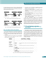
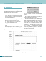
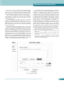
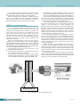
of Achievements in Materials
and Manufacturing Engineering
VOLUME 31
ISSUE 2
December
2008
Remote programming of the Mitsubishi
Movemaster robot by using the
web-based interface
K. Foit*
Institute of Engineering Processes Automation and Integrated Manufacturing Systems,
ul. Konarskiego 18a, 44-100 Gliwice, Poland
* Corresponding author: E-mail address: [email protected]
Received 11.09.2008; published in revised form 01.12.2008
Manufacturing and processing
ABSTRACT
Purpose: The aim of this paper is to present a prototype of web-based programming interface for the Mitsubishi
Movemaster RV-M1 robot.
Design/methodology/approach: The web techniques have been selected due to modularity of this solution and
possibility of use the existing code fragments for elaborating new applications. The previous papers [11-14] have
presented the off-line, remote programming system for the RV-M1 robot. The general idea of this system is a
base for developing a web-based programming interface.
Findings: The prototype of the system has been developed.
Research limitations/implications: The presented system is in the early development stage and there is a lack
of some functions. In the future a visualisation module will be elaborated and the trajectory translator intended
to co-operate with CAD software will be included.
Practical implications: The previous version of the system has been intended for educational purposes. It is
planned that new version will be more flexible and it will have the possibility of being adapted for other devices,
like small PLC’s or other robots.
Originality/value: Remote supervision of machines during a manufacturing process is an actual issue. Most of
automation systems manufacturers produce supervising software for their PLC’s and robots. The Movemaster
RV-M1 robot is an old model and is lack of the high-tech software. On the other hand, the programming and
development of applications for this robot are very easy. The aim of the presented project is to develop a flexible,
remote-programming environment.
Keywords: Automation engineering processes; Robotics: Mechatronics; Technological devices and equipment;
Numerical techniques
1.
Introduction
1. Introduction
Industrial networks are very significant elements of a
contemporary factory. They connect different levels of a
company, giving the possibility of analysing and change of
production parameters from an office room. The network also
connects machines and control systems in order to exchange the
data between them. Programs for controllers are often prepared
and tested on computers, using a virtual environment, then are
uploaded to a real device, using network connections [1-9].
An example of the off-line programming and simulation
package has been presented in the papers [11-14]. The software
package has been written in a high level, object oriented
programming language and it consists of three applications:
x SERWER – the server module,
x ROBO – the programming and simulation module for RV-M1
robot,
© Copyright by International OCSCO World Press. All rights reserved. 2008
Research paper
639
Journal of Achievements in Materials and Manufacturing Engineering
x
KAMROB – the Internet camera and robot control module.
The complete system has been designed to operate with the
Mitsubishi Movemaster RV-M1 robot. It uses a typical personal
computer equipped with serial port and serial connection between
the robot's control unit and the computer. The system is intended
and it should be executed on 32-bit Microsoft Windows platform.
It also requires the TCP/IP network connection. The package has
been intended to run on the Microsoft Windows platform with the
use of a network connection.
The Mitsubishi Movemaster RV-M1is the robot with a five-axis
manipulator and 1.2 kg lifting capacity. The control device of the
robot is equipped with the card containing 16 binary inputs and
outputs. It has also the possibility of connecting it to a personal
computer, using Centronics or RS232 port. Despite the small size of
the robot, it is a typical industrial machine. The robot can be
programmed using a personal computer or by the teaching box – in
case of using the teaching box only positions can be written into
memory. In case of using a computer, program is prepared in
Movemaster Commands language. It has very simple syntax and
allows writing the code in any text editor. The robot can work in
“batch mode” when every command is immediately executed after
sending it to the robot's controller [15]. Due to properties of the
robot’s programming language, allow a user to quickly create its
own communication software for co-operation with the robot.
The main disadvantages of the software described in [11-14]
is that it is intended for the Windows platform only and cannot be
easily ported to the other operating system platform. In the
publications [10-14] a general concept of a platform independent
application has been presented. This paper presents more details
of this idea and describes the prototype of the software.
Volume 31 Issue 2 December 2008
It is a typical configuration with a server on the one side and a
client on the other one. The ROBO application is a client program
and it is installed on the user machine. The SERWER and
KAMROB applications should be installed on the server
computer. There can be one server for both applications or two
machines – one for handling the robot and the other for control
the Internet camera.
The off-line programming and simulation tasks are done by
the ROBO application. A simple program can be also generated
by using a CAD program (for example in AutoCAD). A path is
coded in 3-D by a line entity. Each point represents a position of
the robot’s wrist and the status of the gripper (open or closed) is
described by a point entity. The trajectory is then saved in the
DXF. The ROBO application uses a dictionary file to translate
DXF commands into proper Movemaster Commands directives.
A control panel and a simulation window are two main areas of
the ROBO application’s window (Figure 2). The simulation routine
uses the OpenGL libraries and models created in a 3D modelling
program to achieve the imitation of a real robot’s environment.
There is also possible to add some type of equipment to the virtual
environment: besides an object of manipulation, tables and shelves
can be added to the robot’s scene. All the 3D data can be edited in
the modeller, so the environment and objects could be changed or
updated. There is also the possibility of handling more than one
virtual robot, but this feature requires at least two copies of the
ROBO program connected to the same server.
2.
Thedescription
description
the system
2. The
of theof
existing
existing system and the
andconcept
the concept
the new
ofofthe
newone
one
As it was described in the section 1, the existing system
consists of three applications: the server module, the
programming and simulation module and the Internet camera and
robot control module. The Figure 1 shows an example of a
hardware configuration, used with the software package.
Internet camera
Fig. 2. The main window of the ROBO application with two
robots in simulation area
Client station
(ROBO)
Server computer
(KAMROB, SERWER)
RV-M1 robot
Fig. 1. The example of a hardware configuration used with ROBO
software package
640
Research paper
The papers [10-14] describe all advantages of the system
details. It should be mentioned that the ROBO system has been
developed in collaboration with a student, so it has been primarily
intended for educational purposed. The main drawbacks of the
system are:
x the need of installation on both – server and client side,
x the dependence on the Windows operating system.
In order to eliminate mentioned disadvantages, an idea of a
platform-independent system has been developed. There has been
K. Foit
Manufacturing and processing
one solution based on a web server (Figure 3), and the other based
on the Java environment (Figure 4) – both described with all the
particulars in the papers [10, 14]. In the further part of this paper,
a selected method will be described.
Client computer
Server computer
Robot system
NETWORK
Web browser with plug-ins
Web server, CGI, robot control
Fig. 3. The idea of the web-based programming system
Client computer
Server computer
Robot system
NETWORK
Java Runtime Environment
Web server with Java archives
Fig. 4. The idea of the Java-based programming system
2.1.
The
idea
of the
system
2.1. The
idea
of the
new new
system
It has been decided that for the further development the
method based on a web server will be used. There are some
benefits of this method in comparison with the Java-based system:
x the source code of previously developed system need not be
translated,
x in the case that the server will be run on the Windows
operating system, the new applications could be created on
the base of the existing source code,
x
the interface of the application is provided by the web
resources, so there is no need to develop a graphical user
interface for any new application,
x the system can achieve a high level of modularity, because
applications can be developed as independent modules used
“on demand”,
x the user interface can be easily modified and developed from
scratch to the advanced one,
x there is a possibility of using secure connections certificates
and distributed services,
x there can be alternative user interfaces intended to use on a
different operating system and browser platforms, like
ActiveX, Flash or Java modules.
The first, experimental version of the web-based
programming system has not been equipped with 3-D simulation
module. This feature will be enabled in further versions. It is
planned to use the Adobe Flash, the Shockwave the VRML/X3D
plug-in to build simulation interface. The existing version also has
not video transmission module. These features have not been
important to achieve the basic functionality, so they have been
omitted during the development process. On the other hand, they
require special modules and software to elaborate them.
3. The preliminary version
3. The
preliminary version
of webof web-based
programming
based
programming interface
interface
The preliminary version of web-based programming interface
for the Mitsubishi Movemaster RV-M1 robot has been based on a
web server running on Windows operating system and CGI
(Common Gateway Interface) programs. The CGI allows a web
server to interface with external application software. It means
that a web server process a request from a web browser, transfer
the parameter to an external application and run it. The
application returns output information to the server and the server
transmits it to the client’s browser. In this manner, any application
or script can be called.
Fig. 5. The Control Panel page from the web-based programming interface
Remote programming of the Mitsubishi Movemaster robot by using the web-based interface
641
Journal of Achievements in Materials and Manufacturing Engineering
Volume 31 Issue 2 December 2008
3.1.
The
interface
3.1. The
interface
In this section, the web-based interface will be discussed.
In order to use the interface a user must log in into service.
After logging-in, the main page is displayed in a web browser.
The working area consists of two parts: a menu frame on the left
side and an operation frame on the right (Figure 5).
The menu contains three sections:
x Control Panel – it is used to provide basic administration
tasks for the control unit of the robot,
x Program – this section is related to all the actions connected
with robot’s programming, i.e. program upload and download,
step by step execution, I/O monitor,
x Positions – the section is connected with adding and deleting
positions of the manipulator and defining the status of the
gripper.
The Control Panel menu consists of four commands:
x Nest – resets the manipulator to the origin position (zero),
x Run – executes a program stored in memory,
x Clear program – clears the program area of the controller’s
memory,
x Clear positions – clears the positions area of the controller’s
memory.
All the executed operations should be confirmed by the user.
This is done by using JavaScript code, which displays a
confirmation window. An example of such a window is shown in
Figure 6.
Fig. 6. An example of a confirmation window shown before
operation
The Program and Positions menus are intended for robot’s
programming and adding or deleting positions.
The procedure of programming the robot with use of the web
interface is very similar to a classic way, which is conducted by using
any dedicated application. In the Figure 7 the complete programming
interface is shown. It consists of program editing area, five buttons
and log area. The Programming window format is intended for
program editing. A user can manually enter a program text or paste it
from an external editor. After editing, the code can be copied and
inserted to a text editor. The program can be also uploaded from or
downloaded to a file. This is done by using Download from robot and
Send to robot buttons. A copy of the uploaded or downloaded
program is made automatically after selecting one of the mentioned
buttons. The upload from a file procedure is conducted if the
programming window is empty. Then the small window is displayed,
where a user can select a file to upload.
Fig. 7. The Programming Panel
642
Research paper
K. Foit
Manufacturing and processing
The Clear robot’s progr. button has the same functionality
like the Clear program function in the Control Panel page.
The Step by step exec. button is intended for a program testing. It
sends a program to the controller without line numbers, line by
line, which causes the immediate execution of a sent command.
The Log window displays current robot status. Besides of
error messages it displays also the result of last executed
command. The Clear window button, located under the window,
clears all the messages.
The messages and programming window will be cleared after
leaving the Programming Panel and returning to it later. It is
required to execute the Download or Send functions in case the
programming window to be filled every time the Programming
Panel is loaded. This issue will be overworked in the further
versions of the interface.
The last menu item is the Positions Panel (Fig. 8). This section
is responsible for definition and manipulation of the positions data
set. The panel contains one editing window, where a user can enter
a PD or PC commands sequence. There are three buttons under the
window, which are responsible for communication with the robot’s
control unit. The buttons marked as Download from robot, Send to
robot and Clear robot’s pos. have similar functions as in case of
Programming Panel. A file saving and uploading is done in the
same way as in the Programming Panel with the only a little
difference, that the positions are stored and uploaded without line
numbers, so the directives are executed on the fly. The nesting
procedure is executed automatically before sending any data.
The coordinates can be also entered using the Coordinates
panel section. There are six fields for entering numbers. The Pos.
nr field is for writing the position number, the X, Y and Z are
responsible for coordinates. Finally, the Pitch and Roll describe
the position of the wrist. After entering the numbers, one can use
the Define position button for the automatic generation of the PD
command, which is finally added to the editor window. In order to
use the HERE and P. Clear buttons require defining a position
number only. The first button defines a position on the base on the
current location of the manipulator. The definition is
automatically added to the editor window. This is useful in case of
moving the manipulator using incremental functions, when the
concrete position should be defined. The P. Clear button
generates the PC commands and erases the definition specified by
the position number from the controller’s memory. As opposed to
the HERE and Define position buttons, the PC command is
executed immediately, without inserting it to the editor window.
The last part of the Positions Panel is a section that contains
the position check buttons. There are three buttons:
x INC o – moves the manipulator to the next position on the
position list,
x m DEC – moves the manipulator to the previous position on the
position list,
x Go to position – moves the manipulator to the position number
entered into the text field; if the position does not exist on the list
then an error message is displayed.
Fig. 8. The Positions Panel
Remote programming of the Mitsubishi Movemaster robot by using the web-based interface
643
Journal of Achievements in Materials and Manufacturing Engineering
The presented web-based programming interface consists
only the most frequently used functions. It should assure only the
basic functionality, which is necessary to test an application.
Before executing the Run command or sending the position
data to the manipulator, the Nest command is automatically
called. This is a security issue to assure that before any move is
done, the manipulator always starts from the same position.
3.2.
The
communication
3.2. The
communication
Processing layer
Communication layer
As it was mentioned earlier, the model based on the web
server and CGI has been selected to prepare the interface. The
assumption of this method is that every form is connected with
some action on the server side. The core application is the web
server, which processes requests from a client browser and
intermediates between the client side and applications. Some of
the code is also executed on the client side, mainly the scripts
processed by browser. It provides a better functionality and
maintenance of the forms.
There are several applications on the server side, which are
executed by the CGI action requests. In this case, the modularity
means the better functionality, because there is no need to rebuild one,
huge application – the small application code is better to understand
and for further processing and enhancement. It is also the best method
to avoid errors during the exploitation of the system.
The applications, which are executed on the server, can be
generally divided into three groups:
x the applications providing the communication between the
server computer and the robot’s controller,
x the applications for processing the operation results obtained
from the programs belonging to the group mentioned above
and for generating the appreciate reports in the HTML code,
Volume 31 Issue 2 December 2008
x
the applications providing the maintenance tasks, which are not
directly connected with the communication issues, but can be
used by any application belonging to any group mentioned above.
It is obvious that modularity means also the lower workload of
the overall server system. The applications are loaded on demand.
This may cause some delays, but they are not important from the
user’s point of view, because this is not a real-time system.
The communication process is schematically shown in Figure 9.
The web server application receives a request from a browser and
redirects it by CGI interface to a proper application. The
application processes the information and uses the communication
program to send it to the robot’s controller. The communication
application requests the status of the robot or receives the data,
which are redirected to the other program in order to generate
HTML output. The HTML file is then processed by web server
application and sent by network to the browser.
The maintenance applications are independent programs,
which do not participate directly in the communication process.
The role of these applications is to do some marginal tasks like
setting the serial communication parameters, checking the syntax,
doing characters conversion, etc. These applications are used by
the other, belonging to the first two layers of the system and by
the web server module.
Besides mentioned software installed on the server there is
some more, like script interpreters, database server or preloaded
modules for browsers: plugins, ActiveX, Java applications. At this
stage of development, there is no need to install all of them. Some
actions are realised as scripts, so they need an interpreter, but the
main modules are compiled.
The experimental server system is running on the Windows
platform. This operation system has been selected because existing
source code has been written for the Delphi compiler and thus some
element of it can be used in the new, web-based system.
CGI
Server
Web browser
Maintenance
Fig. 9. The schema of the communication process
644
Research paper
K. Foit
Manufacturing and processing
4.
Conclusions
4. Conclusions
The main aim of this work was to elaborate a web-based
system for programming the Mitsubishi Movemaster RV-M1
robot. This system has been assumed as a platform independent,
so it should be compatible with most available web browsers and
should not use system-dependent modules on the client side.
The other assumption has been made that the first version
should assure only the basic functionality needed for system
testing. The emphasis has been put on the development of the
server side software.
4.1.
The
overall
rating
the project
4.1. The
overall
rating
of theofproject
Hardware requirements. Because of using the modular
structure of the software installed on the server, the system is not
overloaded by time consuming or memory consuming tasks. The
use of simple and lightweight web server software has minimized
the workload of the system. The server has run quite smoothly on
Windows 98 operating system (without any other unnecessary
applications), using Pentium I 200MHz based mainboard and 1GB
hard disk. The client side hardware requirements are connected with
used operating system and a web browser application.
Performance. Because the system is not intended to be real-time,
then the performance is not a priority. The overall performance is
quite well, short delays are the result of sending commands over the
network. They are the most noticeable during the “step by step”
execution of a program or during use of the position checking
function in Positions Panel. The delays are also the result of using the
serial communication between the server and the robot.
Compatibility. The system has been tested on the most popular
web browsers running on the different operating system platform –
no problem has been noticed. Some changes in the appearance of
the page have been caused by the browsers’ rendering engines.
Operation of the system. A web interface is friendlier than
any other. This is also because a web browser is the most used
application by computer users. Of course, the operation of the
web-based programming system for the RV-M1 robot requires at
least basic knowledge of Movemaster Command language and
about operating the robot.
Functionality. The experimental version of the system has
limited functionality because being at testing stage.
4.2.
The
future
plans
4.2. The
future
plans
In the future it is planned to elaborate more functional interface
for the system. The other proposals are:
x the Linux/FreeBSD implementation in order to use the free,
fully configurable operating system,
x the implementation of simulation window with the virtual
workspace,
x the introduction of some elements of visual programming,
x the implementation of the DXF converter [10-14] for
trajectory generation,
x the elaboration of an ActiveX control or DDE server for use
with different Windows applications.
There is also an idea of using a similar system for PLC
controllers. Such a system should be more advanced to implement
the standard PLC’s programming languages.
References
References
[1]
[2]
[3]
[4]
[5]
[6]
[7]
[8]
[9]
[10]
[11]
[12]
[13]
[14]
[15]
T. OtrĊbski, Remote monitoring and control using GPRS
service, Control Engineering Poland 8/36 (2006) 62-64
(in Polish).
A. Presher, The network control of machines – in the
spotlight, Design News 9/16 (2006) 48-51 (in Polish).
S.F. Chan, R. Kwan, Post-processing methodologies for offline robot programming within computer integrated
manufacture, Journal of Materials Processing Technology
139 (2003) 8-14.
G. Yasuda, Distributed autonomous control of modular
robot systems using parallel programming, Journal of
Materials Processing Technology 141 (2003) 357-364.
G. Kost, R. Zdanowicz, Modeling of manufacturing systems
and robot motions, Journal of Materials Processing
Technology 164-165 (2005) 1369-1378.
J. Alvares, J.C. Espindola Ferreira, WebTurning: Teleoperation
of a CNC turning center through the Internet, Journal of
Materials Processing Technology 179 (2006) 251-259.
T.S. Mujber, T. Szecsi, M.S.J. Hashmi, Virtual reality
applications in manufacturing process simulation, Journal of
Materials Processing Technology 155-156 (2004) 1834-1838.
Q. Peng, F.R. Hall, P.M. Lister, Application and evaluation
of VR-based CAPP system, Journal of Materials Processing
Technology 107 (2000) 153-159.
W.B. Lee, C.F Cheung, J.G Li, Applications of virtual
manufacturing in materials processing, Journal of Materials
Processing Technology 113 (2001) 416-423.
K. Foit, J. ĝwider, The project of a platform-independent, offline programming system for industrial robots. Proceedings of
the 7th International Scientific Conference “Computer
Integrated Manufacturing - Intelligent Manufacturing
Systems” CIM'2005, GliwiceíWisáa, 2005, 62-65.
K. Foit, J. ĝwider, D. Mastrowski, The project of an off-line,
remote programming system for Mitsubishi Movemaster
industrial robot, Proceedings of the 13th International
Scientific and Technical Conference “Machine-Building and
Technosphere of the XXI”, Sevastopol, 2006, vol. 4, 252-255.
D. Mastrowski, The system for remote programming,
supervision and simulation of robots, cooperating with
Mitsubishi Movemaster RV-M1 Robot, MSc thesis,
Gliwice, 2006 (in Polish).
J. ĝwider, K. Foit, G. Wszoáek, D. Mastrowski, The off-line
programming and simulation software for the Mitsubishi
Movemaster RV-M1 robot, Journal of Achievements in
Materials and Manufacturing Engineering 20 (2007) 499-502.
J. ĝwider, K. Foit, G. Wszoáek, D. Mastrowski, The system
for simulation and offline, remote programming of the
Mitsubishi Movemaster RV-M1 robot, Journal of
Achievements in Materials and Manufacturing Engineering
25/1 (2007) 7-14.
Mitsubishi Movemaster RV-M1 User’s Manual.
READING DIRECT: www.journalamme.org
645